Fiber Optic Multiplexer Catalog Focal Product Line - Moog Inc
Fiber Optic Multiplexer Catalog Focal Product Line - Moog Inc
Fiber Optic Multiplexer Catalog Focal Product Line - Moog Inc

Create successful ePaper yourself
Turn your PDF publications into a flip-book with our unique Google optimized e-Paper software.
<strong>Fiber</strong> <strong>Optic</strong> <strong>Multiplexer</strong> <strong>Catalog</strong><br />
<strong>Product</strong> <strong>Line</strong>
Custom<br />
Introduction<br />
<strong>Moog</strong> has been developing rugged, subsea fiber-optic multiplexer systems for over 25 years. The expertise gained<br />
designing military telemetry systems for naval towed arrays in the 1980s led to several successful commercial<br />
product lines for video/data multiplexing in Remotely Operated Vehicles (ROVs). Standard multiplexer systems are<br />
now available in several sizes, ranging from the Eurocard-based Model 903 system to smaller form factors, such as<br />
the PC/104-based Model 907 and credit-card-size Model 914. All systems are based on digital signal transmission<br />
using pulses of light through optical fibers. Both legacy multimode fiber cables and higher bandwidth singlemode<br />
fibers are supported.<br />
With over 2,000 systems deployed worldwide, these field-proven, modular systems are widely adopted telemetry<br />
solutions for Remotely Operated Vehicles (ROVs) used in the offshore oil and gas industry and for other applications<br />
in harsh environments. Many custom products have also been developed, particularly for high reliability applications<br />
in the defense and subsea control markets. <strong>Moog</strong> maintains a dedicated team of electronics designers to<br />
support ongoing expansion of existing product lines and provide rapid custom designs for specific applications.<br />
<strong>Moog</strong> Components Group’s <strong>Focal</strong> multiplexers are supported by industry leadership in fiber optic development,<br />
including optical sensors, telemetry systems, connector design, ruggedized optics, and the widest selection of <strong>Fiber</strong><br />
<strong>Optic</strong> Rotary Joints (FORJs). Applications for multiplexers include subsea ROVs, Explosive Ordinance Disposal<br />
(EOD) robots, Aerostat observational pods, industrial tooling stations, surveillance camera pods, remote mining<br />
controls, wind turbines, subsea controls and military vehicles.<br />
2 <strong>Moog</strong> Components Group • www.moog.com/marine
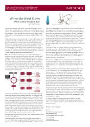
Welcome to the <strong>Moog</strong> Components Group <strong>Focal</strong> <strong>Fiber</strong> <strong>Optic</strong><br />
<strong>Multiplexer</strong> <strong>Catalog</strong>. The fiber optic multiplexer literature, of which<br />
the catalog is a part, is organized in such a way as to make finding<br />
the information you need quick and easy. The catalog is structured<br />
into a selection guide, product guides, datasheets, and technical<br />
appendices.<br />
Other literature on <strong>Focal</strong> multiplexer products, such as user manuals,<br />
configuration drawings, 3D models, market guides, technology briefs<br />
and application notes, can be found at www.moog.com/marine<br />
(select <strong>Focal</strong> <strong>Fiber</strong> <strong>Optic</strong> <strong>Multiplexer</strong>s), or by contacting a sales<br />
representative.<br />
<strong>Multiplexer</strong> Literature Structure<br />
Technical Support<br />
77 Frazee Avenue Tel: 888-302-2263 (USA)<br />
Dartmouth, Nova Scotia +1-902-468-2263<br />
Canada B3B 1Z4 Fax: +1-902-468-2249<br />
NOTE: These are standard commercial products that are available with many options<br />
or configurations not explicitly shown. These options include, but are not limited<br />
to, part substitutions for any other commercial components (e.g. integrated circuits,<br />
optical transceivers, optical couplers/connectors, and electrical connectors) as well as<br />
modifications to support different input power voltages, alternative fiber arrangements,<br />
industrial temperature operation, and new mechanical installations or enclosures.<br />
Table Of Contents<br />
<strong>Product</strong> Selection Guide .......................... 4<br />
903 <strong>Product</strong> Guide................................... 5<br />
903 Datasheet ................................... 15<br />
903HD Datasheet .............................. 17<br />
907 <strong>Product</strong> Guide................................. 19<br />
907-R/C Datasheet ............................ 31<br />
907Plus Datasheet ............................ 33<br />
907-GEM Datasheet .......................... 35<br />
907V Datasheet ................................. 37<br />
907-HDM2 Datasheet ........................ 39<br />
907-SER Datasheet ........................... 41<br />
907-ECL Datasheet ........................... 43<br />
907-HDV Datasheet .......................... 45<br />
907-GBE Datasheet .......................... 47<br />
907-GBE2 Datasheet ........................ 49<br />
907-GBES Datasheet ........................ 51<br />
907-DIAG-E Datasheet ...................... 53<br />
907-CWDM Datasheet ...................... 55<br />
907-FOS Datasheet ........................... 57<br />
912 <strong>Product</strong> Guide................................. 59<br />
912-OEO-4R Datasheet .................... 64<br />
912-OEO-8 Datasheet ....................... 66<br />
914 <strong>Product</strong> Guide................................. 68<br />
914-R/C Datasheet ............................ 73<br />
914-HDM Datasheet .......................... 75<br />
914-HDV Datasheet .......................... 77<br />
914-GBE Datasheet .......................... 79<br />
Market Specific <strong>Product</strong>s ....................... 81<br />
920-EDM Datasheet .......................... 82<br />
922 Datasheet ................................... 84<br />
Custom <strong>Product</strong> Guide .......................... 86<br />
Technical Information............................. 90<br />
<strong>Moog</strong> Components Group • www.moog.com/marine 3 3<br />
Model Model 903 Model 907 Model 912 912 Model 914 914 Market Specific Custom
Model 907 Model 903<br />
Model 912<br />
Model 914<br />
Market Specific<br />
Custom<br />
<strong>Product</strong> Selection Guide<br />
A wide variety of signal types are supported by <strong>Moog</strong>’s <strong>Focal</strong> multiplexers and OEO converters, per the tables below.<br />
Custom solutions provide support for additional signal formats or unique combinations of standard protocols. Application<br />
specific products may be customized to reduce size or cost, optimize packaging, extend environmental performance, and<br />
integrate more directly with other equipment. Since new products are continually added, please contact <strong>Moog</strong> for updates.<br />
Model 903 - 3U Eurocard-based modular system with<br />
slide-in card replacements. Suitable as standalone<br />
sub-racks or for 19” rack installations. Easy front panel<br />
access to all I/O and fiber.<br />
Model 907 - PC/104 card-based modular multiplexer<br />
system stacked with standoffs. Typically cards are<br />
installed in existing enclosures but are also available with<br />
housings and pressure tolerant configurations.<br />
Model 914 - Credit card size boards (1/2 PC/104) suitable<br />
for small vehicles and other tight spaces. Typically cards<br />
are installed in existing enclosures but are also available<br />
with housings.<br />
Model 912 - OEM converters in Eurocard sizes for 3U<br />
racks. Used for boosting optical signals, converting<br />
between singlemode and multimode signals, and optical<br />
multiplexing to reduce fiber counts.<br />
Custom Mux - Custom designed with a variety of form<br />
factors and interface signals for specific applications.<br />
Custom systems can be designed to integrate with other<br />
platforms, such as VME, Ethernet, and Modbus.<br />
Model<br />
Video/Analog Signals<br />
903 907 912 914 Custom<br />
MUX<br />
Composite (NTSC, PAL) l l l l<br />
S-Video (Y/C) l l l<br />
Component (YPbPr, RGB) l l l<br />
Audio/Hydrophone l l l l<br />
Analog Sonar (MS900) l l l l<br />
Resolver/Encoder l l l<br />
4-20 mA l l l<br />
Sensor (Voltage Output)<br />
Digital Video Signals<br />
l l l<br />
SD-SDI (SMPTE 259M) l l l l<br />
HD-SDI (SMPTE 292M) l l l l l<br />
3G HD-SDI (SMTPE 424M) l l l l<br />
CameraLink l<br />
GigE Vision<br />
Serial Data Signals<br />
l l l l<br />
RS-232 l l l l<br />
RS-485/422 l l l l<br />
TTL l l l l<br />
Responder Trigger l l l l<br />
IRIG Timing l l l l<br />
ECL/PECL l l l<br />
LVDS l l l<br />
On/Off Controls (TOR)<br />
Network/Bus Signals<br />
l l l<br />
10/100M Ethernet l l l l l<br />
Gigabit Ethernet l l l l l<br />
10G Ethernet l<br />
Tritech ARCNET l l l l<br />
PROFIBUS l l l l<br />
CAN Bus, Device Net l l l<br />
EtherCAT, PROFINET l l l l<br />
USB 2.0, 3.0<br />
Diagnostics<br />
l<br />
LEDs On Board l l l l l<br />
LEDS, External l l<br />
Serial Port (RS-232) l l<br />
Ethernet Port l l l<br />
Modbus TCP/RTU l l l<br />
4 <strong>Moog</strong> Components Group • www.moog.com/marine
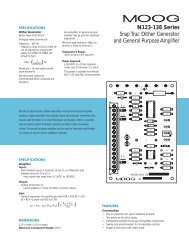
The <strong>Focal</strong> Model 903<br />
product family provides a rugged<br />
video/data multiplexer and fiber optic<br />
communication system for Remotely Operated Vehicles (ROVs)<br />
and other industrial machines operating in harsh environments.<br />
A rack based 3U height (5.25 inch) Eurocard system with a flexible architecture that supports reconfiguration<br />
and expansion of the system to meet application specific requirements. Expansion cards include analog<br />
video, serial data, Ethernet, sonar, and others. Media converter cards are available for HD video and Gigabit<br />
Ethernet.<br />
Typical Applications<br />
The Model 903 product family is ideally suited<br />
to meet the needs of medium sized rugged<br />
fiber optic converters, such as:<br />
• Work class Remotely Operated Vehicles (ROVs)<br />
• Military Remotely Operated Vehicles (ROVs)<br />
• Subsea mining<br />
Model 903 systems are assembled<br />
from five main categories of items:<br />
• <strong>Fiber</strong>-optic motherboards (FMB)<br />
• Chassis and backplanes<br />
• Media converters<br />
• Expansion cards<br />
• System modules<br />
Model 903 <strong>Multiplexer</strong><br />
<strong>Product</strong> Guide<br />
<strong>Moog</strong> Components Group • www.moog.com/marine 5 5<br />
Model 903 Model 907 Model 912 Model 914 Market Specific Custom
Model 907 Model 903<br />
Model 912<br />
Model 914<br />
Market Specific<br />
Custom<br />
Model 903 <strong>Product</strong> Guide<br />
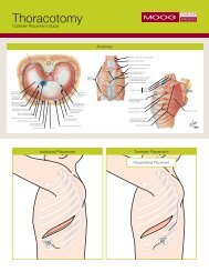
<strong>Fiber</strong>-<strong>Optic</strong> Motherboards (FMB)<br />
A Model 903 system contains one remote (subsea) FMB and one console (surface) FMB. The FMB converts electrical<br />
signals from a Eurocard backplane into a bidirectional fiber-optic telemetry link. Expansion cards (also called interface<br />
boards) can be added to the chassis for analog video, Ethernet, serial data such as RS-232 and RS-485/422, and many<br />
special signal formats for sonars, responder triggers, and other devices.<br />
HOST ELECTRONICS<br />
FOCAL 903 SYSTEM FOCAL 903 SYSTEM HOST ELECTRONICS<br />
FIBER-OPTIC<br />
MOTHERBOARD<br />
(FMB)<br />
OPTICAL FIBER<br />
FIBER-OPTIC<br />
MOTHERBOARD<br />
(FMB)<br />
VIDEO<br />
VIDEO<br />
MULTIPLE VIDEO<br />
EXPANSION CARD<br />
EXPANSION CARD<br />
MULTIPLE VIDEO<br />
903 FMBs come standard with redundant fiber operation and have an option for Coarse Wavelength Division Multiplexing<br />
(CWDM) transceivers.<br />
Motherboard FMB-X-2.5<br />
Description <strong>Fiber</strong>-optic motherboard<br />
Part Number 903-5082-XX (R)<br />
903-5083-YY (C)<br />
Features Redundant-fiber operation with auto fiber switching;<br />
100 Mbps Ethernet; remote diagnostics<br />
Baud Rate 2.5 Gbaud<br />
Wavelength Standard: 1310/1550 nm, CWDM: 1471 – 1611 nm, 20 nm spacing<br />
Card Width 8 HP (40.64 mm)<br />
For CWDM wavelengths, substitute the following two digit code for XX/YY:<br />
47 = 1471 nm, 49 = 1491 nm, 51 = 1511 nm, 53 = 1531 nm, 55 = 1551 nm, 57 = 1571 nm, 59 = 1591 nm, 61 = 1611 nm.<br />
Other wavelengths available upon request.<br />
FMB-X-2.5 cards provide more advanced diagnostic features and higher bandwidth than older FMB cards (i.e. FMB-VTX/<br />
FMB-VRX), and may be installed as upgrades to older multiplexer system as long as:<br />
• Any medium speed backplanes are replaced with -X backplanes;<br />
• Both console and remote FMBs are FMB-X-2.5 types<br />
6 <strong>Moog</strong> Components Group • www.moog.com/marine
Chassis and Backplanes<br />
Model 903 FMBs, media converters, expansion cards and system cards are<br />
housed in a Eurocard chassis. The backplane allows for communication between<br />
the FMB and the expansion cards. The backplane can also provide power to the<br />
installed cards. All chassis are available in a variety of widths to accommodate one<br />
FMB, up to two video and four data expansion cards. Cards come in standard widths<br />
of 4 HP, 6 HP, or 8 HP, where 1 HP is 5.08 mm (0.2 inch). Chassis are also available<br />
with additional slots for media converters.<br />
903 Chassis CBP-100-XR CBP-200-XR CBP-231 CBP-241<br />
Description Single High<br />
Density Remote<br />
Chassis<br />
Dual High<br />
Density Remote<br />
Chassis<br />
Standard Chassis Extended<br />
Chassis<br />
Part Number 903-0004-03 903-0005-12 903-6746-00 (R) 903-6745-01 (R)<br />
903-6747-00 (C) 903-0007-06 (C)<br />
Rack Width 12 HP (60.96 mm) 16 HP (81.28 mm) 40 HP (203.2 mm, R) 50 HP (254 mm, R)<br />
42 HP (213.4 mm, C) 50 HP (254 mm, C)<br />
No. Expansion<br />
Cards Supported<br />
1 HD Slot 2 HD Slots 5 (2 Video, 3 Data) 6 (2 Video, 4 Data)<br />
No. Media Converter<br />
Cards Supported<br />
0 0 3 4<br />
(R) = Remote, (C) = Console<br />
Model 903 <strong>Product</strong> Guide<br />
Don’t see a size or configuration to suit your application? We have built hundreds of different chassis and<br />
backplane configurations. Contact <strong>Moog</strong> to see how we can meet your specific application requirements.<br />
For users of older 903 systems, backplanes were available in either ‘medium’ or ‘high’ speed versions. All new backplanes<br />
are ‘high’ speed versions only.<br />
<strong>Moog</strong> Components Group • www.moog.com/marine 7 7<br />
Model 903 Model 907 Model 912 Model 914 Market Specific Custom
Model 907 Model 903<br />
Model 912<br />
Model 914<br />
Market Specific<br />
Custom<br />
Model 903 <strong>Product</strong> Guide<br />
Media Converter Cards<br />
Media converter cards provide direct electrical to optical signal conversion and<br />
transmit over one or two dedicated optical fibers. A number of signal formats are<br />
supported, including ECL/PECL signals for Cypress HOTLink and multi-beam sonar<br />
links; high-definition digital video (SMPTE-292); and one, two, and four channels of<br />
Gigabit Ethernet.<br />
HOST ELECTRONICS<br />
HD VIDEO<br />
10/100/100<br />
ETHERNET<br />
Media converters may be deployed on their own dedicated optical fiber or configured to support CWDM optical transceivers<br />
that allow for optically multiplexing of multiple cards using one of the passive 903 CWDM <strong>Optic</strong>al cards.<br />
Media<br />
Converter<br />
Description HD-SDI/SDI<br />
Media Converter<br />
FOCAL 903 SYSTEM FOCAL 903 SYSTEM HOST ELECTRONICS<br />
HD-SDI MEDIA<br />
CONVERTER<br />
GIGABIT ETHERNET<br />
MEDIA CONVERTER<br />
HDSDI-SM HDV-02 GBE-02 GBES-SM ECL-02<br />
Dual HD-SDI/SDI<br />
Media Converter<br />
OPTICAL FIBER<br />
OPTICAL FIBER<br />
Dual Gigabit<br />
Ethernet<br />
Media Converter<br />
HD-SDI MEDIA<br />
CONVERTER<br />
GIGABIT ETHERNET<br />
MEDIA CONVERTER<br />
Quad Gigabit<br />
Ethernet Switch<br />
Media Converter<br />
HD VIDEO<br />
10/100/100<br />
ETHERNET<br />
Dual ECL/PECL<br />
Part Number1 903-5060-XX 903-5092-XX 903-5091-XX 903-5087-XX 903-5050-XX<br />
Channel<br />
Direction<br />
Unidirectional Unidirectional Bidirectional Bidirectional Unidirectional<br />
NRZ Data Rate 143 – 1485 143 – 1485 Mbps 10/100/1000 10/100/1000 30 – 150 Mbps<br />
Mbps<br />
per Channel<br />
Mbps<br />
Mbps<br />
I/O Connectors 1 x SMB In, 2 x SMB In, 2 x RJ-45 4 x RJ-45 2 x SMB In,<br />
1 x SMB Out 2 x SMB Out<br />
2 x SMB Out<br />
Card Width 4 HP (20.2 mm) 4 HP (20.2 mm) 4 HP (20.2 mm) 4 HP (20.2 mm) 4 HP (20.2 mm)<br />
1 XX – CWDM wavelength (47 = 1471, 49 = 1491, 51 = 1511, 53 = 1531, 55 = 1551, 57 = 1571, 59 = 1591, 61 = 1611 nm). Other wavelengths available by request.<br />
8 <strong>Moog</strong> Components Group • www.moog.com/marine
Expansion Cards<br />
A maximum of four data expansion cards and two analog video expansion cards can be added to a 903 chassis. An<br />
Adaptable Interface Board (AIB) expansion card allows standard AIB plug-in modules to be employed as well.<br />
Expansion<br />
Card<br />
VIB-TX<br />
VIB-RX<br />
Description 2 Part<br />
Number<br />
4-Channel Video<br />
Expansion Card<br />
HDB-TX High-Density<br />
Video/Data<br />
Expansion Card 1<br />
AIB-4 Adaptable<br />
Interface<br />
4-Channel<br />
Expansion Card<br />
CIB-10 Control Interface<br />
Expansion Card<br />
DIB-232-16 RS-232<br />
16-Channel<br />
Expansion Card<br />
907-232-E RS-232<br />
8-Channel<br />
Expansion Card<br />
907-485-E RS-485<br />
8-Channel<br />
Expansion Card<br />
EIB-10/100 Ethernet<br />
Expansion Card<br />
903-0014-00 (R)<br />
903-0015-00 (C)<br />
1 The HDB-TX is compatible with a High Density remote chassis only.<br />
2 Expansion cards are 4 HP (20.2 mm) in width.<br />
Model 903 <strong>Product</strong> Guide<br />
Supported<br />
Video<br />
Formats<br />
NTSC, PAL,<br />
RGB,<br />
S-Video<br />
(Y/C)<br />
903-5006-00 (R) NTSC, PAL,<br />
RGB,<br />
S-Video<br />
(Y/C)<br />
Video<br />
Channels<br />
Supported<br />
Data<br />
Formats<br />
On-board<br />
Data<br />
Channels<br />
4 NA NA<br />
4 4 x RS-232,<br />
4 x AIB<br />
903-5003-02 NA NA AIB 4<br />
903-5040-00 NA NA Bidirectional<br />
Channels<br />
(ON/OFF)<br />
903-5020-00 NA NA RS-232 16<br />
903-5056-00 NA NA RS-232 8<br />
903-5053-00 NA NA RS-485,<br />
RS-422<br />
903-5044-00 NA NA 10/100<br />
Base-T(X)<br />
Ethernet<br />
<strong>Moog</strong> Components Group • www.moog.com/marine 9 9<br />
8<br />
10<br />
8<br />
3<br />
Model 903 Model 907 Model 912 Model 914 Market Specific Custom
Model 907 Model 903<br />
Model 912<br />
Model 914<br />
Market Specific<br />
Custom<br />
Model 903 <strong>Product</strong> Guide<br />
System Cards<br />
System cards provide the support required to adapt the Model 903 architecture to many different<br />
applications. These cards provide mechanical integration of the Model 907 and Model 914 into<br />
Eurocard form-factor, and operation with a wide range of AC or DC input power.<br />
System Card PSU-AC PSU-24V PSU-48V 907-EURO4 914-EURO2<br />
Description Selectable AC<br />
Power Supply<br />
Module<br />
Isolated DC-DC<br />
Power Supply<br />
Card for 18-36<br />
VDC Input<br />
Isolated DC-DC<br />
Power Supply<br />
Card for 36-60<br />
VDC Input<br />
907 to Eurocard<br />
Adaptor<br />
914 to Eurocard<br />
Adaptor<br />
Part Number 903-0022-00 903-0022-02 903-0022-01 907-0005-00 903-7208-00<br />
(No 914s)<br />
Features/<br />
Options<br />
Supports<br />
115/230 VAC<br />
input, provides<br />
backplane power<br />
Supports<br />
18-36 VDC input,<br />
provides<br />
backplane power<br />
Supports<br />
36-60 VDC input,<br />
provides<br />
backplane power<br />
Allows use of<br />
one Model 907<br />
in a Eurocard<br />
System<br />
Allows use of two<br />
Model 914 in a<br />
Eurocard System<br />
Card Width 8 HP (40.64 mm) 8 HP (40.64 mm) 8 HP (40.64 mm) 4 HP (20.32 mm) 4 HP (20.32 mm)<br />
10 <strong>Moog</strong> Components Group • www.moog.com/marine
Adaptable Interface Boards (AIB)<br />
AIB Card AIB-232 AIB-485 AIB-HYDRO AIB-ARCNET AIB-MS900 AIB-CAN Bus<br />
Description 1 x RS-232 1 x RS-485/422 1 x Hydrophone 1 x Tritech<br />
ARCNET<br />
Model 903 <strong>Product</strong> Guide<br />
AIB plug-in modules are compatible with the Model 903, the Model 907, and the Model 914 product lines. The AIB-4 has<br />
four sockets for separate AIB plug-in modules. AIB plug-in modules are available for a variety of data signals and analog<br />
formats.<br />
903-AIB Supports Four AIB Plug-in Modules<br />
AIB plug-in modules are used to convert the signal interface format to a TTL format, which is then accessed through the<br />
Eurocard backplane. AIB plug-ins support standard serial data interfaces (RS-232/485/422), hydrophone and other audio<br />
signals, various digital and analog sonar telemetry, and control networks, such as CAN and Profibus.<br />
1 x MS-900<br />
Analog Sonar<br />
1 x CAN Bus<br />
Bridge<br />
Part Number 903-0251-00 903-0252-00 903-0244-00 903-0261-00 903-0250-00 903-0297-00<br />
Channel<br />
Direction<br />
Bidirectional Bidirectional Unidirectional Bidirectional Bidirectional Bidirectional<br />
NRZ Data Rate 120 kbps 2.5 Mbps 30 Hz - 30 kHz 156 kbps/78 kbps 5 - 30 kHz, 62.5 kbps - 1<br />
BW<br />
380 - 580 kHz Mbps<br />
I/O Connectors 4-pin WAGO headers on 903-AIB adapter card<br />
Options Responder AC-Coupled IRIG-B, Audio Terminations Low Speed Repeater<br />
Trigger 485, TTL<br />
Telemetry (LF) Mode<br />
<strong>Moog</strong> Components Group • www.moog.com/marine 11 11<br />
Model 903 Model 907 Model 912 Model 914 Market Specific Custom
Model 907 Model 903<br />
Model 912<br />
Model 914<br />
Market Specific<br />
Custom<br />
Model 903 <strong>Product</strong> Guide<br />
<strong>Optic</strong>al Cards<br />
Systems with only one motherboard or media converter typically transmit at an optical wavelength of 1310 nm for uplink<br />
and 1550 nm for downlink. In larger systems with multiple FMBs, media converters and expansion cards, fiber-optic signals<br />
may be combined on a single fiber using a Coarse Wavelength Division <strong>Multiplexer</strong> (CWDM) to take advantage of the high<br />
bandwidth of optical fiber. Standard CWDM optical wavelengths are separated by 20 nm and have center wavelengths<br />
of 1471 nm to 1611 nm. Bidirectional optical signals occupy two distinct wavelengths. For example, a 903 GBE-02 media<br />
converter using CWDM wavelengths may use 1471 nm for uplink traffic, and 1491 nm for downlink traffic.<br />
To provide redundant communications between host electronics in the case of a fiber-optic cable failure, the FMB is fitted<br />
with a fiber-optic splitter, while the mating system is fitted with a fiber-optic switch. All optical traffic from the splitter system is<br />
transmitted along both fiber-optic cables. The switch system can automatically select the best fiber to use for communications.<br />
RX<br />
TX<br />
RX<br />
TX<br />
RX<br />
TX<br />
RX<br />
TX<br />
RX<br />
TX<br />
RX<br />
TX<br />
WDM<br />
1x2<br />
SPLITTER<br />
8 CHANNEL<br />
CWDM<br />
OPTICAL FIBER<br />
Redundant <strong>Fiber</strong><br />
OPTICAL FIBER<br />
8-Wavelength CWDM<br />
2x1<br />
SWITCH<br />
8 CHANNEL<br />
CWDM<br />
<strong>Optic</strong>al Card CWDM-8<br />
Description 8-Channel CWDM <strong>Optic</strong>s Card, 1471 - 1611 nm, singlemode, 20 nm spacing<br />
Part Number 903-5251-00<br />
Features/Options 4 HP (20.2 mm)<br />
12 <strong>Moog</strong> Components Group • www.moog.com/marine<br />
WDM<br />
TX<br />
RX<br />
TX<br />
RX<br />
TX<br />
RX<br />
TX<br />
RX<br />
TX<br />
RX<br />
TX<br />
RX
Key Specifications<br />
Form Factor and Chassis • Model 903 cards use the standard 3U Eurocard form factor of 3.937 x 6.29<br />
inches (100 x 160 mm)<br />
• Expansion cards communicate over the Eurocard backplane to the FMB fiber<br />
optic motherboard<br />
• Cards plug into the Eurocard chassis, and are electrically connected via the<br />
backplane connector<br />
• Various width chassis are available for remote and console<br />
Analog Video • Formats supported: NTSC or PAL, RGB or S-Video (Y/C)<br />
• Sampled at 15 MHz, providing minimum 6 MHz bandwidth<br />
• Voltage: 1.2 Vp-p max<br />
• Impedance: 75 Ω<br />
Digital HD-SDI Video • Format supported: HD-SDI (SMPTE-292)<br />
• Data rate: 1.485 Gbps (3 Gbps option)<br />
• Voltage: 800 mV P-P nominal<br />
• Impedance: 75 Ω<br />
Model 903 <strong>Product</strong> Guide<br />
Ethernet Options • Support for full duplex 10/100/1000 Base-T(X) Ethernet<br />
• Physical-layer (PHY) media converters for low latency<br />
• Switched Ethernet for additional port count<br />
• Multiplexed options for multiple isolated channels<br />
Data Options • RS-232: bidirectional channels, 120 kbaud max<br />
• RS-422/485: 5 Mbps NRZ<br />
• AIB expansion card daughter-cards support additional channels of RS-232,<br />
RS- 422/485, CAN Bus, Tritech Arcnet, and MS900 Sonar<br />
• Other signals such as TTL, TOR, and support for Profibus<br />
Power • Built in or cassette-style power supply with options for 120 VAC 50/60 Hz,<br />
230 VAC 50/60 Hz, 24 VDC (18-36 VDC) and 48 VDC (36-60V DC)<br />
• Input Protection: over-voltage, reverse polarity, over-current<br />
<strong>Moog</strong> Components Group • www.moog.com/marine 13 13<br />
Model 903 Model 907 Model 912 Model 914 Market Specific Custom
Model 907 Model 903<br />
Model 912<br />
Model 914<br />
Market Specific<br />
Custom<br />
Model 903 <strong>Product</strong> Guide<br />
<strong>Optic</strong>al Options • <strong>Optic</strong>al <strong>Fiber</strong>: 1 or 2 singlemode (9/125 μm)<br />
• Wavelengths: 1310/1550 nm standard, CWDM options available<br />
• Flux Budget: 20 dB minimum standard (others available)<br />
• Connectors: ST, others available<br />
Diagnostics Support • Diagnostics extracted from the FMB cards in both remote and console<br />
stacks using a 10 Base-T Ethernet or RS-232 link<br />
• <strong>Optic</strong>al transceiver data including Tx-power, Rx-power, bias current,<br />
temperature, voltage and more<br />
• Card identity, serial number<br />
• Built-in web server<br />
• Terminal diagnostics through RS-232 port on FMB<br />
• Compatible with VDM software<br />
Call or email our knowledgeable Application Engineers for more information:<br />
902-468-2263 or focal@moog.com<br />
14 <strong>Moog</strong> Components Group • www.moog.com/marine
903<br />
Video/Data <strong>Multiplexer</strong><br />
Description<br />
Model 903 multiplexers provide highly reliable fiber optic<br />
transmission of video and data signals in demanding environments.<br />
A modular Eurocard design based around the FMB-X-2.5 fiberoptic<br />
motherboard and a wide range of supported video and data<br />
formats ensure the flexibility needed for easy system configuration.<br />
Individual data channels can be mixed and matched with a variety of<br />
plug-in interface modules. Advanced optical multiplexing (CWDM,<br />
DWDM) enables system expansion to 32 video and 256 data<br />
channels as well as additional high data rate signals such as HD-<br />
SDI, ECL for advanced sonars, and Gigabit Ethernet. Integrated<br />
diagnostics and software provide real time display and logging of<br />
all critical parameters.<br />
Features<br />
• Compact, modular, 3U sub-rack<br />
• Highest quality digitized video<br />
• Wide range of supported video and data formats<br />
• Robust protection on I/O lines<br />
• Singlemode and multimode fiber options<br />
• Automatic fiber switching<br />
• Extensive diagnostics monitors power system, video, data,<br />
temperature and fiber-optic link<br />
Benefits<br />
• Easily reconfigured at card level and individual channel level<br />
• Diagnostics verifies health of umbilical and tether cables<br />
• Continually updated with the newest data formats, including<br />
HD-SDI, and Gigabit Ethernet, to provide an extended upgrade<br />
path (custom interfaces available)<br />
• Successful installation assured by factory acceptance tests at<br />
temperature extremes and 20 years of experience providing<br />
technical support for fiber-optic systems<br />
Model 903 Datasheet<br />
Typical Applications<br />
• Remotely operated vehicles (ROV)<br />
• FPSO communications process<br />
control<br />
• Defense systems<br />
• Research ROV<br />
• Subsea mining<br />
<strong>Moog</strong> Components Group • www.moog.com/marine 15 15<br />
Model 903 Model 907 Model 912 Model 914 Market Specific Custom
Model 907 Model 903<br />
Model 912<br />
Model 914<br />
Market Specific<br />
Custom<br />
Model 903 Datasheet<br />
Video<br />
No. Slots<br />
No. Channels<br />
Format<br />
Digitization<br />
Bandwidth<br />
SNR<br />
Impedance<br />
Data<br />
No. Slots<br />
Serial Data<br />
Ethernet<br />
ARCNET<br />
Hydrophone<br />
Analog Sonar<br />
Control <strong>Line</strong>s<br />
ECL (optical)<br />
Other<br />
Electrical<br />
903 Dimensions<br />
1 - 2 (3 - 8 optional with CWDM)<br />
4 per slot (8 with switched video)<br />
NTSC/PAL composite signals, RGB, Y/C<br />
(S-Video), YPrPb, HD-SDI optional<br />
10-bit<br />
6.0 MHz<br />
> 60 dB (62 dB typical)<br />
75 Ohms<br />
2 - 4<br />
4 - 16 channels per slot RS-232/485/422,<br />
TTL (2.5 Mbps NRZ max)<br />
3 ports, 10 Base-T (electrical)<br />
3 ports, 100 Base-TX (optical)<br />
1 port, 10/100 BaseT(X) (electrical on front<br />
panel of FMB)<br />
4 ports, 1000 Base TX (optical)<br />
1 - 4 Tritech ARCNET channels per slot<br />
1 - 4 channels per slot, 12bit, 16 Hz 28 kHz<br />
1 - 4 bidirectional channels per slot MS900/971<br />
compatible<br />
10 bidirectional control lines per slot<br />
1 - 2 high speed ECL/sonar lines per slot,<br />
30 - 150 Mbaud, 50/75 Ohm in/out<br />
Digital video, industrial control bus, CAN Bus,<br />
IRIG-B, HD-SDI<br />
Power Supply AC: 120/240 VAC (50/60 Hz)<br />
DC: 24 VDC, 48 VDC<br />
< 40 W each end typical<br />
Isolation Varies with signal type (consult factory)<br />
<strong>Optic</strong>al<br />
Note: Standard chassis shown with typical cards. Racks are available in a variety of widths up to 84 HP, corresponding to a size compatible<br />
with installation in a standard 19” equipment rack.<br />
These are standard commercial products that are available with many options or configurations not explicitly shown.<br />
<strong>Optic</strong>al <strong>Fiber</strong> 1 or 2 singlemode (9/125 µm)<br />
1 or 2 multimode (50/125 µm and 62.5/125 µm)<br />
Baud Rate FMB-X-2.5: 2.5 Gbaud, uplink and downlink<br />
Wavelength 1310/1550 nm standard<br />
(CWDM Optional, 1471-1611 nm)<br />
Flux Budget > 20 dB (24 dB typical)<br />
Mechanical<br />
Chassis<br />
Eurocard 3U subracks (28 - 84 HP)<br />
Rack width (mm) = 9.65 + (#HP x 5.08)<br />
100 x 160 mm cards<br />
Dimensions Height = 133 mm, Depth = 210 mm<br />
Remote Rack Width = 28 - 84 HP<br />
Console Rack Width = 34 - 84 HP<br />
Fans add 27 - 29 mm to rack height<br />
See 903HD datasheet for 12 or 16 HP remote<br />
racks. Custom racks available<br />
Weight Remote 5.0 kg (11 lb), typical<br />
Console 5.4 kg (12 lb), typical<br />
Connectors<br />
<strong>Optic</strong>al<br />
Video<br />
Data<br />
Diagnostics<br />
Environmental<br />
ST front panel bushing (FC optional)<br />
16 <strong>Moog</strong> Components Group • www.moog.com/marine<br />
SMB<br />
2 x 6-pin Wago, BNC, D-Sub, RJ45, SMB<br />
DB-9S (Console FMB)<br />
Temperature -10°C to +60°C (operational)<br />
-20°C to +85°C (storage)<br />
Humidity 85% RH, non-condensing<br />
Vibration 5 g, 251000 Hz, 3 axes<br />
Shock<br />
30 g, 11 ms half sine, 3 axes<br />
Remote (ROV) Module Dimensions in inches [millimeters]<br />
Console (Surface) Module
903HD<br />
High Density Video/Data <strong>Multiplexer</strong><br />
Description<br />
The high density 903HD remote module provides the features of<br />
a fullsized subsea video/data multiplexer in a package of half the<br />
volume. This reduction enables installation in constrained spaces<br />
while supporting transmission of 4-8 high quality video channels<br />
and 8-16 bidirectional data channels over a single optical fiber.<br />
Since the 903HD uses the same FMB-X-2.5 fiber multiplexer boards<br />
(FMBs) as the standard 903, including CWDM versions, it supports<br />
singlemode or multimode fiber as well as dual fiber operation with<br />
automatic fiber switching. Data channels are easily configured with<br />
plug-in modules for various data formats. A standard 903 console<br />
module at the surface includes powerful diagnostics software with<br />
realtime display and logging of critical remote/console parameters.<br />
Features<br />
• Less than half the size of the standard FO903<br />
• Wide range of supported video and data formats<br />
• High quality digitized video<br />
• Singlemode and multimode fiber options<br />
• Extensive diagnostics monitors power systems, video, data,<br />
temperature and fiber-optic link<br />
Benefits<br />
• Easily reconfigured at card level and individual channel level<br />
• Diagnostics verifies health of umbilical and tether cables<br />
• Continually updated with the newest data formats, including<br />
HD-SDI, and Gigabit Ethernet, to provide an extended upgrade<br />
path<br />
• Custom interfaces available<br />
• Successful operation assured by factory acceptance tests at<br />
extremes and 20 years of experience providing technical<br />
support for fiber optic systems<br />
Model 903 Datasheet<br />
Typical Applications<br />
• Workclass Remotely Operated<br />
Vehicles (ROVs)<br />
• Defense systems<br />
• Subsea Mining<br />
<strong>Moog</strong> Components Group • www.moog.com/marine 17 17<br />
Model 903 Model 907 Model 912 Model 914 Market Specific Custom
Model 907 Model 903<br />
Model 912<br />
Model 914<br />
Market Specific<br />
Custom<br />
Model 903 Datasheet<br />
Video<br />
No. Channels<br />
Format<br />
Digitization<br />
Bandwidth<br />
SNR<br />
Data<br />
RS-232<br />
AIB Modules<br />
RS-232<br />
RS-422/485<br />
ARCNET<br />
903HD Dimensions<br />
4 per HDB-TX card<br />
NTSC, PAL (optional Y/C, RGB)<br />
10-bit<br />
> 6 MHz<br />
> 60 dB (62 dB typical)<br />
4 channels per HDB-TX (120 kbps NRZ)<br />
4 plug-in modules per HDB-TX card<br />
1 channel per plug-in (120 kbps NRZ)<br />
1 channel per plug-in (2.5 Mbps NRZ)<br />
1 Tritech sonar ARCNET port per plug-in<br />
(156 kbps max.)<br />
Hydrophone 1 uplink analog channel per plug-in<br />
12-bit resolution, 28 kHz bandwidth<br />
Analog Sonar 1 MS900/971 analog sonar link per plug-in<br />
Other<br />
Diagnostics<br />
CAN Bus, Ethernet<br />
LEDs<br />
Power (electrical), optical link, optical fault,<br />
Ethernet port status, serial data Tx/Rx, video<br />
sync, over temperature limit<br />
Ethernet to PC Diagnostics from remote and console through<br />
Ethernet port on console FMB<br />
Dimensions in inches [millimeters]<br />
<strong>Optic</strong>al<br />
<strong>Optic</strong>al <strong>Fiber</strong> 1 or 2 singlemode (9/125 µm) or multimode<br />
(50/125 µm and 62.5/125 µm)<br />
Baud Rate FMB-X-2.5: 2.5 Gbaud uplink/downlink<br />
Wavelength 1310/1550 nm, CWDM (1471-1611 nm)<br />
Flux Budget > 20 db (24 db typical)<br />
Mechanical<br />
Chassis*<br />
Weight*<br />
Connectors<br />
<strong>Optic</strong>al<br />
Video<br />
Data<br />
Eurocard 3U subrack, 12 HP and 16 HP<br />
CBP-100-MR uses CBP-121-MC console<br />
CBP-200-MR uses CBP-241 HC console<br />
< 2 kg (4.4 lb), CBP-100-MR (typical)<br />
< 3 kg (6.6 lb), CBP-200-HR<br />
ST/PC (FC/PC optional)<br />
18 <strong>Moog</strong> Components Group • www.moog.com/marine<br />
SMB<br />
4-pin WAGO Gage Clamp, data I/O box or<br />
ribbon cable (optional) at front panel<br />
Diagnostics DB-9S (Console Module)<br />
Environmental<br />
Temperature -10°C to +60°C (operational)<br />
-20°C to +85°C (storage)<br />
Humidity 85% RH, noncondensing<br />
Vibration 5 g, 25-1000 Hz, 3 axes<br />
Shock 30 g, 11 ms half sine, 3 axes<br />
Options Extended temperature, stress screened or<br />
qualified<br />
*See Model 903 data sheet for console module specifications.<br />
Note: Dual (16 HP) and single (12 HP) high density chassis shown with 1 - 2 high density boards (HDB-TX), fiber multiplexer boards (FMB-VTX), and fiber<br />
option for use with automatic fiber switching at console module.<br />
These are standard commercial products that are available with many options or configurations not explicitly shown.
Model 907 <strong>Multiplexer</strong><br />
<strong>Product</strong> Guide<br />
The Model 907 was designed for applications requiring the transmission of video and/or data over an optical<br />
link. A modular PC/104 form-factor and flexible design architecture supports reconfiguration and expansion<br />
of the multiplexer system to fit the specific data requirements of each application.<br />
Typical Applications<br />
The Model 907 product family is suited particularly well to applications requiring small and ruggedized<br />
fiber-optic converters, such as:<br />
• Remotely Operated Vehicles (ROVs)<br />
• Explosive Ordinance Disposal (EOD)<br />
and pipe inspection robots<br />
• Industrial automation equipment<br />
• Wind energy turbines<br />
• Video security networks<br />
• Defense and other high reliability<br />
ruggedized applications including<br />
radar, ground vehicles, and<br />
Electro-<strong>Optic</strong> (EO) targeting<br />
and surveillance pods<br />
Model 907 systems are assembled<br />
from four main categories of cards:<br />
• <strong>Multiplexer</strong> motherboards<br />
• Media converters<br />
• Expansion cards<br />
• System modules<br />
The family of <strong>Focal</strong> Model 907<br />
products provides compact and<br />
rugged video/data multiplexers and<br />
fiber-optic transmission systems.<br />
<strong>Moog</strong> Components Group • www.moog.com/marine 19 19<br />
Model 903 Model 907 Model 912 Model 914 Market Specific Custom
Model 907 Model 903<br />
Model 912<br />
Model 914<br />
Market Specific<br />
Custom<br />
Model 907 <strong>Product</strong> Guide<br />
<strong>Multiplexer</strong> Motherboards<br />
A Model 907 system consists, as a minimum, of a Model 907 remote motherboard (multiplexer), and a Model 907 console<br />
motherboard. Each motherboard can operate as a standalone multiplexer used to combine analog video, digital video, or<br />
Ethernet with on-board or backplane serial data such as RS-232 and high-speed RS-485/422. Motherboards can all be<br />
stacked together and communicate with expansion cards to send and receive data over the backplane for additional data<br />
capabilities.<br />
HOST ELECTRONICS FOCAL 907 SYSTEM FOCAL 907 SYSTEM HOST ELECTRONICS<br />
MULTIPLE VIDEO MULTIPLE VIDEO<br />
MULTIPLE RS-232<br />
VIDEO + DATA<br />
MOTHERBOARD OPTICAL FIBER<br />
VIDEO + DATA<br />
MOTHERBOARD<br />
MULTIPLE RS-232<br />
MULTIPLE RS-485 MULTIPLE RS-485<br />
10/100<br />
ETHERNET<br />
907 motherboards can be optically configured with Coarse Wave Division <strong>Multiplexer</strong> (CWDM) transceivers for use with<br />
passive 907 optical cards. High power transceivers are available for demanding optical systems, and low cost transceivers<br />
are available for cost sensitive applications.<br />
Motherboard 907-R/C 907+ 907V 907-HDM2 907-GEM<br />
Description 3-Channel<br />
Video/Data Mux<br />
Part Number 907-0001-XX (R)<br />
907-0002-XX (C)<br />
Supported<br />
Video Formats<br />
Video<br />
Channels<br />
Supported<br />
Data Formats<br />
On-board Data<br />
Channels<br />
Support for<br />
E-Diagnostics<br />
NTSC, PAL,<br />
RGB, S-Video<br />
(Y/C)<br />
4-Channel<br />
Video/Data Mux<br />
907-0025-XX (R)<br />
907-0026-XX (C)<br />
NTSC, PAL,<br />
RGB,<br />
S-Video (Y/C)<br />
6-Channel<br />
Video Mux<br />
907-0023-XX (R)<br />
907-0024-XX (C)<br />
NTSC, PAL,<br />
RGB, S-Video<br />
(Y/C)<br />
2-Channel<br />
HD-SDI/Data Mux<br />
907-0050-XX (R)<br />
907-0051-XX (C)<br />
HD-SDI<br />
(SMPTE-292)<br />
4-Channel<br />
Gigabit Ethernet Mux<br />
907-0060-XX<br />
GigE Vision<br />
3 4 6 1-2 HD-SDI 4 max<br />
RS-232,<br />
RS-485/422,<br />
Backplane data<br />
ETHERNET<br />
EXPANSION CARD<br />
RS-232,<br />
RS-485/422,<br />
Backplane data<br />
ETHERNET<br />
EXPANSION CARD<br />
Backplane data RS-232,<br />
RS-485/422,<br />
Backplane data<br />
10/100<br />
ETHERNET<br />
10/100/1000<br />
Base-T Ethernet,<br />
Backplane Data<br />
6 6 None 2 4 Ethernet<br />
No Yes Yes Yes Yes<br />
20 <strong>Moog</strong> Components Group • www.moog.com/marine
Media Converter Cards<br />
Media converter cards provide direct electrical to optical signal conversion and transmit over one or two dedicated optical<br />
fibers. A number of signal formats are supported, including ECL/PECL signals for Cypress HOTLink and multi-beam sonar<br />
links; high-definition digital video (SMPTE-292); and one, two, or four isolated channels of Gigabit Ethernet.<br />
HOST ELECTRONICS<br />
HD VIDEO<br />
10/100/100<br />
ETHERNET<br />
Media converters may be deployed as standalone cards running on their own dedicated optical fiber or configured to support<br />
CWDM optical transceivers that allow for optical multiplexing of multiple cards using one of the passive 907-CWDM optical<br />
cards. High power transceivers are available for demanding optical systems, as well as, low cost transceivers for cost<br />
sensitive applications.<br />
Media<br />
Converter<br />
Description Single HD-SDI,<br />
SDI<br />
907-HDV 907-GBE 907-GBE2 907-GBES 907-ECL<br />
Single Gigabit<br />
Ethernet Media<br />
Converter<br />
Model 907 <strong>Product</strong> Guide<br />
FOCAL 907 SYSTEM FOCAL 907 SYSTEM HOST ELECTRONICS<br />
HD-SDI MEDIA<br />
CONVERTER<br />
GIGABIT ETHERNET<br />
MEDIA CONVERTER<br />
OPTICAL FIBER<br />
OPTICAL FIBER<br />
Dual Gigabit<br />
Ethernet Media<br />
Converter<br />
HD-SDI MEDIA<br />
CONVERTER<br />
GIGABIT ETHERNET<br />
MEDIA CONVERTER<br />
Quad Gigabit<br />
Ethernet Switch<br />
HD VIDEO<br />
10/100/100<br />
ETHERNET<br />
Single ECL/PECL/<br />
Hotlink Media<br />
Converter<br />
Part Number 907-0022-XX 907-0021-XX 907-0030-XX 907-0027-XX 907-0019-XX<br />
Channel Direction Unidirectional Bidirectional Bidirectional Bidirectional Unidirectional<br />
NRZ Data Rate 143 – 1485 10/100/1000 10/100/1000 10/100/1000 30 – 600 Mbps<br />
Mbps<br />
Mbps<br />
Mbps<br />
Mbps<br />
I/O Connectors 2 x SMB In, 1 x RJ-45 2 x RJ-45 4 x RJ-45 2 x SMB In,<br />
2 x SMB Out<br />
2 x SMB Out<br />
Support for<br />
E-Diagnostics<br />
YES NO YES YES YES<br />
<strong>Moog</strong> Components Group • www.moog.com/marine 21 21<br />
Model 903 Model 907 Model 912 Model 914 Market Specific Custom
Model 907 Model 903<br />
Model 912<br />
Model 914<br />
Market Specific<br />
Custom<br />
Model 907 <strong>Product</strong> Guide<br />
Expansion Cards<br />
Up to six expansion cards may be stacked on a 907 motherboard using the backplane connector for power and signals. Each<br />
expansion card provides an increased number of data channels or added signal formats not supported by the motherboard<br />
directly. An Adaptable Interface Board (AIB) expansion card allows standard AIB plug-in daughter-card modules to be<br />
employed as well.<br />
Expansion<br />
Card<br />
907-232 8-Channel<br />
RS-232<br />
Card<br />
907-485 8-Channel<br />
RS-485/<br />
422 Card<br />
907-SER 8-Channel<br />
RS-232/485/<br />
422 Card 5<br />
907-ADC/DAC 8-Channel,<br />
8/12-bit<br />
ADC/DAC3 Card<br />
907-AUDIO 4-Channel,<br />
24-bit Audio<br />
Card<br />
907-CIB 4-Channel<br />
Control<br />
Interface4 Card<br />
907-AIB Dual Socket<br />
AIB Adaptor<br />
907-EIBS 10 Mbps<br />
Ethernet<br />
Switch Card<br />
Description Part Number BP<br />
Channels<br />
used<br />
Max. Data<br />
Rate<br />
I/O Connectors<br />
907-0212-00 1 120 kbps 4 x 8 pin Molex<br />
907-0217-00 1, 2, 4 250 kbps to<br />
2.5 Mbps 1<br />
907-0242-00 1, 2, 4 250 kbps to<br />
2.5 Mbps<br />
ADC: 907-0218-00<br />
DAC: 907-0219-00<br />
1 50 kHz<br />
Bandwidth<br />
907-0228-00 1 20 kHz<br />
Bandwidth<br />
907-0231-00 1 50 kHz<br />
Updates<br />
907-0204-00 1, 2 Up to<br />
2.5 Mbps 2<br />
4 x 8 pin Molex<br />
4 x 8 pin Molex<br />
2 x 8 pin Molex<br />
4 x 2 pin WAGO<br />
2 x 3 pin WAGO<br />
4 x 2-Pin WAGO<br />
2 x 3-Pin WAGO<br />
2 x 4-Pin WAGO<br />
907-0222-00 1 10 Mbps 3 x RJ-45<br />
1. Maximum NRZ data rate increases with number of backplane channels used on the motherboard<br />
2. Maximum NRZ data rate or analog bandwidth depends on the AIB plug-in modules installed.<br />
3. Use 907-ADC Analog Input Card, P/N 907-0218-00 with complementary 907-DAC Analog Output Card, P/N 907-0219-00<br />
4. CIB inputs are individually configurable as switch or voltage controlled; CIB outputs are all solid state relays, max. current 250 mA.<br />
5. 907-SER supports Ethernet diagnostics when used with the 907-DIAG-E<br />
22 <strong>Moog</strong> Components Group • www.moog.com/marine
Adaptable Interface Boards (AIB)<br />
AIB Card AIB-232 AIB-485 AIB-HYDRO AIB-ARCNET AIB-MS900 AIB-CAN Bus<br />
Description 1 x RS-232 1 x RS-485/<br />
422<br />
Model 907 <strong>Product</strong> Guide<br />
AIB plug-in modules are compatible with the Model 903, the Model 907, and the Model 914 product lines. The 907-AIB has<br />
two sockets for separate AIB plug-in modules. AIB plug-in modules are available for a variety of low speed data signals.<br />
907-AIB Supports Two AIB Plug-in Modules<br />
AIB plug-in modules are used to convert the signal interface format to a TTL format, which is then accessed through the<br />
expansion port on the 907 motherboard. AIB plug-ins support standard serial data interfaces (RS-232/485/422), hydrophone<br />
and other audio signals, various digital and analog sonar telemetry, and control networks, such as CAN Bus and Profibus.<br />
1 x Hydrophone 1 x Tritech<br />
ARCNET<br />
1 x MS-900<br />
Analog Sonar<br />
1 x CAN Bus<br />
Bridge<br />
Part Number 903-0251-00 903-0252-00 903-0244-00 903-0261-00 903-0250-00 903-0297-00<br />
Channel<br />
Direction<br />
Bidirectional Bidirectional Unidirectional Bidirectional Bidirectional Bidirectional<br />
NRZ Data Rate 120 kbps 2.5 Mbps 30 Hz - 30 kHz 156 kbps/78 5 - 30 kHz, 62.5 kbps - 1<br />
BW<br />
kbps 380 - 580 kHz Mbps<br />
I/O Connectors 4-pin WAGO headers on 907-AIB adapter card<br />
Options Responder AC-Coupled IRIG-B, Audio Terminations Low Speed Repeater Mode<br />
Trigger 485, TTL<br />
Telemetry (LF)<br />
<strong>Moog</strong> Components Group • www.moog.com/marine 23 23<br />
Model 903 Model 907 Model 912 Model 914 Market Specific Custom
Model 907 Model 903<br />
Model 912<br />
Model 914<br />
Market Specific<br />
Custom<br />
Model 907 <strong>Product</strong> Guide<br />
<strong>Optic</strong>al Cards<br />
Systems with only one motherboard or media converter typically transmit at an optical wavelength of 1310 nm for uplink and<br />
1550 nm for downlink. In larger systems with multiple 907 motherboards, media converters and expansion cards, fiber-optic<br />
signals may be combined on a single fiber using a Coarse Wavelength Division <strong>Multiplexer</strong> (CWDM) to take advantage of<br />
the high bandwidth of optical fiber. CWDM optical wavelengths are separated by 20 nm and range from 1471 nm to 1611<br />
nm. Bidirectional optical signals occupy two distinct wavelengths. For example a 907-GBE Media Converter using CWDM<br />
wavelengths may use 1471 nm for uplink traffic and 1491 nm for downlink traffic.<br />
To provide redundant communications between host electronics in the case of a fiber-optic cable failure, one system may<br />
be fitted with a fiber-optic splitter, while the other system is fitted with a fiber-optic switch. All optical traffic from the splitter<br />
system is transmitted along both fiber-optic cables. The switch system can manually or digitally (TTL) select one of the two<br />
fibers for communication.<br />
RX<br />
TX<br />
RX<br />
TX<br />
WDM<br />
RX<br />
TX<br />
RX<br />
TX<br />
RX<br />
TX<br />
WDM WDM<br />
OPTICAL FIBER<br />
WDM<br />
WDM<br />
Integrated WDM for 1310/1550 nm on One <strong>Fiber</strong><br />
4 CHANNEL<br />
CWDM<br />
1x2<br />
SPLITTER<br />
OPTICAL FIBER<br />
OPTICAL FIBER<br />
4-Wavelength CWDM<br />
OPTICAL FIBER<br />
WDM, Splitter and Switch<br />
4 CHANNEL<br />
CWDM<br />
2x1<br />
SWITCH<br />
24 <strong>Moog</strong> Components Group • www.moog.com/marine<br />
WDM<br />
TX<br />
RX<br />
WDM<br />
TX<br />
RX<br />
TX<br />
RX<br />
TX<br />
RX<br />
TX<br />
RX
<strong>Optic</strong>al Cards<br />
<strong>Optic</strong>al Card Description Part Number Features/Options<br />
907-WDM<br />
WDM <strong>Optic</strong>s Card,<br />
1310/1550 nm,<br />
Singlemode<br />
907-CWDM CWDM <strong>Optic</strong>s Card,<br />
1471/1491 nm with<br />
1310/1550 nm<br />
Bypass, Singlemode<br />
907-CWDM-MM CWDM <strong>Optic</strong>s Card,<br />
1471/1491 nm with<br />
1310/1550 nm<br />
Bypass, Multimode<br />
907-CWDM-4R1 CWDM <strong>Optic</strong>s Card,<br />
1471 - 1531 nm,<br />
Singlemode,<br />
20 nm Spacing<br />
907-CWDM-8R CWDM <strong>Optic</strong>s Card,<br />
1471 - 1611 nm,<br />
Singlemode,<br />
20 nm Spacing<br />
907-SPLIT-SM 1 x 2 <strong>Fiber</strong> Splitter<br />
Card, Singlemode<br />
907-FOS-SM 1 x 2 <strong>Fiber</strong> Switch<br />
Card, Singlemode<br />
Model 907 <strong>Product</strong> Guide<br />
907-0015-35 Card-mounted, PC/104<br />
907-0015-00 1310/1550 nm bypass port for easy<br />
upgrade of existing 1310/1550 nm<br />
system<br />
907-0015-02 1310/1550 nm bypass port for easy<br />
upgrade of existing 1310/1550 nm<br />
system<br />
907-0015-03 Optional 1310 nm<br />
Bypass Port<br />
907-0015-20 Optional 1310 nm<br />
Bypass Port<br />
907-0015-05 Provides redundant fiber operation<br />
907-0015-06 Provides fiber-optic switch with<br />
manual or remote digital control<br />
(TTL)<br />
<strong>Moog</strong> Components Group • www.moog.com/marine 25 25<br />
Model 903 Model 907 Model 912 Model 914 Market Specific Custom
Model 907 Model 903<br />
Model 912<br />
Model 914<br />
Market Specific<br />
Custom<br />
Model 907 <strong>Product</strong> Guide<br />
Oil Filled/Pressure Tolerant<br />
Standard Model 907 products require a 1 atmosphere (ATM) enclosure when used in subsea applications. However, specific<br />
907 products are available in pressure tolerant versions for use in Pressure Balanced Oil Filled (PBOF) applications. Refer<br />
to application note AN-03 for a detailed analysis of pressure tolerant electronics.<br />
Card Card Type Description Part Number Pressure Rating 2<br />
907+P <strong>Multiplexer</strong><br />
Motherboard<br />
4-Channel Video/Data Mux 907-0035-XX1 6000 psi<br />
907V-P <strong>Multiplexer</strong><br />
6-Channel Video Mux<br />
907-0033-03 3000 psi<br />
Motherboard<br />
With Bidi Transceiver<br />
907V-P <strong>Multiplexer</strong><br />
Motherboard<br />
6-Channel Video Mux 907-0033-XX1 6000 psi<br />
907-GBE-P Media Converter Single Gigabit Ethernet<br />
Media Converter<br />
907-0043-XX1 6000 psi<br />
907-GBE2-P Media Converter Dual Gigabit Ethernet<br />
Media Converter<br />
907-0031-XX1 6000 psi<br />
907-GBES-P Media Converter Quad Gigabit Ethernet Switch 907-0028-XX1 6000 psi<br />
907-232-P Expansion Card 8-Channel RS-232 Card 907-0212-02 6000 psi<br />
907-485-P Expansion Card 8-Channel RS-485/422 907-0217-01 6000 psi<br />
907-SER-P Expansion Card 8-Channel RS-232/485/422 907-0242-02 6000 psi<br />
907-CIB-P Expansion Card 4-Channel Control Interface 907-0231-01 6000 psi<br />
907-AIB-P Expansion Card Dual Socket AIB Adaptor 907-0204-01 6000 psi<br />
907-EIBS-P Expansion Card 10 Mbps Ethernet Switch Card 907-0222-01 6000 psi<br />
907-CWDM-4R1-P <strong>Optic</strong>al Card CWDM <strong>Optic</strong>s Card,<br />
1471-1531 nm, Singlemode,<br />
20 nm Spacing<br />
907-0015-32 6000 psi<br />
907-CWDM-8R-P <strong>Optic</strong>al Card CWDM <strong>Optic</strong>s Card,<br />
1471-1611 nm, Singlemode,<br />
20 nm Spacing<br />
907-0015-21 6000 psi<br />
907-WDM-P <strong>Optic</strong>al Card WDM <strong>Optic</strong>s Card, 1310/1550 nm,<br />
Singlemode<br />
907-0015-36 6000 psi<br />
907-SPLIT-SM-P <strong>Optic</strong>al Card 1 x 2 <strong>Fiber</strong> Splitter Card,<br />
Singlemode<br />
907-0015-05 6000 psi<br />
1. XX – CWDM wavelength (47 = 1471, 49 = 1491, 51 = 1511, 53 = 1531, 55 = 1551, 57 = 1571, 59 = 1591, 61 = 1611 nm). Other wavelengths available by request.<br />
2. 6000 psi = 412 bar = 4 km ocean depth and 3000 psi = 206 bar = 2 km ocean depth<br />
26 <strong>Moog</strong> Components Group • www.moog.com/marine
System Cards<br />
System cards provide the support functions required to adapt the Model 907 architecture to many different applications.<br />
These cards provide mechanical integration of the 907 into Eurocard form-factor, electrical interoperability with the<br />
standardized PC/104 backplane, operation with 18-30 VDC input, and 907 diagnostics.<br />
System Card 907-DIAG-E 907-DC-24 907-EURO<br />
Description Ethernet Diagnostic Card Isolated DC-DC<br />
Power Supply Card<br />
for 18-30 VDC Input<br />
Eurocard Adaptor<br />
Part Number 907-0238-00 907-0233-00 907-0005-xx<br />
907-0006-xx<br />
Features/Options Ethernet Output. API and<br />
sample GUI available. Reads<br />
diagnostics from compatible<br />
cards in 907 stacks.<br />
Model 907 <strong>Product</strong> Guide<br />
Supports 18-30 VDC input,<br />
provides multiple +5 VDC<br />
outputs<br />
4 HP and 8 HP options<br />
available, typically supplied<br />
assembled with 907 card<br />
<strong>Moog</strong> Components Group • www.moog.com/marine 27 27<br />
Model 903 Model 907 Model 912 Model 914 Market Specific Custom
Model 907 Model 903<br />
Model 912<br />
Model 914<br />
Market Specific<br />
Custom<br />
Model 907 <strong>Product</strong> Guide<br />
Ethernet Diagnostics<br />
Specific 907 products are compatible with the 907 Ethernet diagnostics. The<br />
907-DIAG-E system card combined with the diagnostics .NET graphical user<br />
interface (GUI) allow for real time diagnostics of both remote and console<br />
multiplexer motherboards, media converters and expansion cards.<br />
Parameters include optical transmit power, optical receive power, optical<br />
transmitter temperature, voltages, and many more. The GUI can be configured to provide<br />
alarms on conditions and log data. An application programming interface (API) is available to<br />
provide a simple interface for customer developed software.<br />
Model 907 Ethernet Diagnostics<br />
Compatible Cards<br />
Card Card Type<br />
907+ <strong>Multiplexer</strong> Motherboard<br />
907V <strong>Multiplexer</strong> Motherboard<br />
907-HDM2 <strong>Multiplexer</strong> Motherboard<br />
907-GEM <strong>Multiplexer</strong> Motherboard<br />
907-HDV Media Converter<br />
907-GBE2 Media Converter<br />
907-GBES Media Converter<br />
907-ECL Media Converter<br />
907-SER Expansion Card<br />
28 <strong>Moog</strong> Components Group • www.moog.com/marine
Key Specifications<br />
Form Factor and Mounting • Model 907 cards use the standard PC/104 form factor of 3.55 x 3.775 inches<br />
(90 x 96 mm)<br />
• The cards are outfitted with a PC/104 connector to provide backplane<br />
connectivity between multiple cards assembled in a vertical stack<br />
• Cards stack one on top of the other, supported by 0.625 inch standoffs fitted into<br />
mounting holes on the corners of the card, and are electrically connected via<br />
the PC/104 connector<br />
• Some stack configurations require fiber pigtails to optically connect one card<br />
to another<br />
• 19-inch EIA rack mount enclosures and custom enclosures available upon<br />
request<br />
Analog Video • Formats supported: NTSC or PAL, RGB, S-Video (Y/C), YPbPr<br />
• 8-10-bit digitization, 6 MHz bandwidth<br />
• Voltage: 1.2 Vp-p maximum<br />
• Impedance: 75 Ω<br />
Digital HD-SDI Video • Format supported: HD-SDI (SMPTE-292)<br />
• Electrical Data Rate: 1.485 Gbps (3 Gbps option)<br />
• Voltage: 800 mV P-P nominal<br />
• Impedance: 75 Ω<br />
Model 907 <strong>Product</strong> Guide<br />
Ethernet Options • Support for full duplex 10/100/1000 Base-T(X) Ethernet<br />
• Physical-layer (PHY) media converters for low latency<br />
• GigE vision cameras supported<br />
• Switched Ethernet for additional port count<br />
• Multiplexed options for multiple isolated channels<br />
Data Options • RS-232: bidirectional channels, 120 kbaud maximum<br />
• RS-422/485: 5 Mbps NRZ<br />
• AIB plug-in cards support additional channels of RS-232,<br />
RS- 422/485, CAN Bus, Tritech ARCNET, and MS900 Sonar<br />
• Other signals such as TTL, On/Off, and support for Profibus<br />
<strong>Moog</strong> Components Group • www.moog.com/marine 29 29<br />
Model 903 Model 907 Model 912 Model 914 Market Specific Custom
Model 907 Model 903<br />
Model 912<br />
Model 914<br />
Market Specific<br />
Custom<br />
Model 907 <strong>Product</strong> Guide<br />
Power • Input Voltage: +5 VDC ± 10%, regulated, 0.5-1.0 A typical (2.5 W to 5.0 W),<br />
per card<br />
• Input Protection: over-voltage, reverse polarity, over-current<br />
• Model 907 motherboards obtain power through a 2-pin Molex power connector<br />
and are capable of providing power to other cards in the stack through the<br />
backplane PC/104 interface<br />
• If regulated +5 VDC power supplies are not available, the 907-DC-24 PSU card<br />
can be added to a 907 stack to generate multiple +5 VDC supplies from 18-30<br />
VDC input<br />
Pressure Tolerant • Pressure tolerant versions of multiplexer motherboards, media converters<br />
and expansion cards are available for pressures up to 6000 psi<br />
<strong>Optic</strong>al Options • <strong>Optic</strong>al <strong>Fiber</strong>: 1 or 2 singlemode (9/125 µm), 1 or 2 multimode<br />
(50/125 µm and 62.5/125 µm)<br />
• Wavelengths: 1310/1550 nm standard, CWDM options available<br />
• Flux Budget: 20 dB minimum standard (others available)<br />
• Connectors: LC or ST, depending on card (others available)<br />
Diagnostics Support • Diagnostics extracted from compatible cards in both remote and console stacks<br />
using 907-DIAG-E card. Diagnostic data is accessible over a 10/100 Base-T(X)<br />
Ethernet link to the 907-DIAG-E<br />
• <strong>Optic</strong>al transceiver data including Tx/Rx power, bias current, temperature,<br />
voltage, and more<br />
• Card identity, serial number<br />
• Motherboard data-channel activity<br />
• Ethernet port link speed and activity indicators<br />
• Sample .NET GUI and full API is available<br />
• LED diagnostics also available on board<br />
Call or email our knowledgeable Application Engineers for more information:<br />
902-468-2263 or focal@moog.com<br />
30 <strong>Moog</strong> Components Group • www.moog.com/marine
907-R/C<br />
Video/Data <strong>Multiplexer</strong><br />
Description<br />
The 907 video/data multiplexer provides digital transmission over 1<br />
or 2 singlemode or multimode optical fibers for 3 high quality analog<br />
video channels and 6 bidirectional data channels (4 x RS-232 and<br />
2 x RS485/422/TTL) in a single, compact PC/104 form-factor card.<br />
Expansion cards may be stacked to convert (i.e. replace) data<br />
channels on the motherboard to other data formats, such as<br />
Ethernet, analog sonar, hydrophone and Tritech ARCNET, or to<br />
replace each motherboard channel with up to 8 lower data-rate<br />
serial channels. <strong>Optic</strong>al power budgets are typical 20 - 24 dB with<br />
2 km of multimode fiber or 10 km of singlemode fiber. LEDs provide<br />
on-board diagnostics for data, video and optical link status.<br />
Features<br />
• High quality digitized video<br />
• Standalone, single card multiplexer<br />
• Supports up to six 907 expansion cards<br />
• Standard PC/104 form factor<br />
• Rugged design for harsh environments, including pressure<br />
tolerant version<br />
• On-board diagnostic LEDs for power, optical link, and video<br />
sync<br />
• Wide range of supported video and data formats<br />
• Singlemode and multimode fiber options<br />
• CWDM expansion for high speed data links, such as HD-SDI,<br />
ECL and Gigabit Ethernet<br />
Benefits<br />
• Highest channel density allows extremely compact solution for<br />
space limited application<br />
• Easily reconfigured with a wide range of expansion cards<br />
including the same AIB plug-in modules used on the Model<br />
903<br />
• Extended temperature options allows use in the harshest<br />
environments<br />
• Successful operation assured by factory acceptance test at<br />
temperature extremes and 20 years of experience providing<br />
technical support for fiber-optic systems<br />
Model 907 Datasheet<br />
Typical Applications<br />
• Subsea Remotely Operated<br />
Vehicles (ROVs) and tether<br />
management systems<br />
• Pipe inspection robots<br />
• Bomb disposal robots<br />
• Armoured vehicles<br />
<strong>Moog</strong> Components Group • www.moog.com/marine 31 31<br />
Model 903 Model 907 Model 912 Model 914 Market Specific Custom
Model 907 Model 903<br />
Model 912<br />
Model 914<br />
Market Specific<br />
Custom<br />
Model 907 Datasheet<br />
Video<br />
No. Channels<br />
Format<br />
Digitization<br />
Bandwidth<br />
SNR<br />
Impedance<br />
Options<br />
Data<br />
RS-232<br />
RS-485/422<br />
Options<br />
<strong>Optic</strong>al<br />
<strong>Optic</strong>al <strong>Fiber</strong><br />
Baud Rate<br />
Wavelength<br />
Flux Budget<br />
Options<br />
907 Dimensions<br />
3<br />
NTSC/PAL, RGB, Y/C (S-Video), YPrPb<br />
8-bit (3 video channels)<br />
10-bit (2 video channels)<br />
6.0 MHz<br />
> 56 dB (62 dB typical)<br />
75 Ohms<br />
1 x non-video analog channel (1 Vpp)<br />
1 x 12-bit, 12 Mhz analog channel<br />
(replaced all video channels)<br />
4 channels (120 kbps NRZ max.)<br />
2 channels RS-485 (2.5 Mbps NRZ max.)<br />
Supports AC-coupled RS-485, TTL<br />
907 expansion cards<br />
1 or 2 singlemode (9/125 µm)<br />
multimode (50/125 µm)<br />
600 Mbaud<br />
1310/1550 nm standard<br />
(CWDM optional, 1471 - 1611 nm)<br />
> 20 dB (24 dB typical)<br />
Bidi (bidirectional) transceivers<br />
Dimensions in inches [millimeters] 907 shown with singlemode WDM option<br />
Electrical<br />
Power Supply +5.0 VDC ± 10%, regulated<br />
Power Used 5 W typical (10 W max.)<br />
Grounding Shared common for power, data, video<br />
Options<br />
Mechanical<br />
Isolated power/data card<br />
Dimensions PC/104 (form-factor only)<br />
Weight<br />
< 120 g (0.26 lb)<br />
Options<br />
Connectors<br />
Custom enclosures, Eurocard adapter<br />
<strong>Optic</strong>al<br />
Single ST/PC<br />
Video<br />
SMB<br />
Data (Serial) 3 x 8-pin Molex (Micro-Fit Series)<br />
Power<br />
Environmental<br />
2-pin Molex, 0.156 inch pin spacing<br />
Temperature -10°C to +60°C (operational)<br />
-40°C to +85°C (storage)<br />
Humidity 85% RH, non-condensing<br />
Vibration 5 g, 25 - 1000 Hz, 3 axes<br />
Shock<br />
30 g, 11 ms half sine, 3 axes<br />
Options 3000 psi pressure tolerant, extended<br />
temperature, stress screened or qualified<br />
Note: These are standard commercial products that are available with many options or configurations not explicitly shown.<br />
32 <strong>Moog</strong> Components Group • www.moog.com/marine
907PLUS<br />
Video/Data <strong>Multiplexer</strong><br />
Description<br />
The 907Plus is a multiplexer that extends the capabilities of<br />
standard 907 motherboards with an added video channel,<br />
galvanically isolated data channels, and a comprehensive,<br />
integrated diagnostics network. System expansion is even easier<br />
with a rapidly growing family of compatible expansion cards and<br />
media converters. A diagnostics add-on card is available that offers<br />
end-to-end performance monitoring and identification for multi-card<br />
systems via an Ethernet connection at the console, and Graphical<br />
User Interface (GUI) software.<br />
Expansion cards may be stacked on the motherboard to add up<br />
to 48 data channels in a variety of formats, including RS-232, RS-<br />
485/422, TTL, Ethernet, CAN Bus, analog sonar, hydrophone,<br />
audio, and Tritech ARCNET. Depending on transceiver options,<br />
optical power budgets are typically 20-26 dB with 10 km or more<br />
of singlemode fiber.<br />
Features<br />
• I2C bus supports diagnostic communications with expansion<br />
cards and media converters<br />
• Galvanically isolated data serial data channels<br />
• Compatible with 907-DIAG-E diagnostic card and Graphical<br />
User Interface (GUI) software<br />
• On-board diagnostic LEDs for power, optical link, and video<br />
sync, and serial data Tx/Rx<br />
• Interchangeable SFP optical transceiver<br />
• Supports up to six 907 expansion cards<br />
Benefits<br />
• Isolated data channels provide more robust interface to<br />
external equipment<br />
• Supports a wide range of optical options, including CWDM<br />
wavelengths and multimode configurations<br />
• No motherboard data channels are disabled when expansion<br />
cards are added<br />
• Simplifies troubleshooting with advanced diagnostics<br />
Model 907 Datasheet<br />
Typical Applications<br />
• Remotely Operated Vehicles (ROVs<br />
• Pipe inspection robots<br />
• Bomb disposal robots<br />
• Video Security Systems<br />
• Tether management systems<br />
• Tactical Networks<br />
• Aerostat Balloons<br />
<strong>Moog</strong> Components Group • www.moog.com/marine 33 33<br />
Model 903 Model 907 Model 912 Model 914 Market Specific Custom
Model 907 Model 903<br />
Model 912<br />
Model 914<br />
Market Specific<br />
Custom<br />
Model 907 Datasheet<br />
Video<br />
No. Channels 4<br />
Format<br />
NTSC/PAL, RGB, Y/C (S-Video), YPrPb<br />
Digitization 10-bit<br />
Bandwidth 6.0 MHz<br />
SNR<br />
> 56 dB (60 dB typical)<br />
Impedance<br />
Data<br />
75 Ohms<br />
RS-232<br />
4 isolated channels (120 kbps NRZ)<br />
RS-485/422 2 isolated RS-485, or 1 isolated RS-422 (2.5 Mbps<br />
NRZ)<br />
Options<br />
<strong>Optic</strong>al<br />
907 expansion cards<br />
<strong>Fiber</strong> Type 1 or 2 singlemode (9/125 µm)<br />
Format<br />
AME-EP (<strong>Moog</strong> proprietary)<br />
Baud Rate 1.25 Gbaud<br />
Wavelength 1310/1550 nm standard<br />
(CWDM optional, 1471 - 1611 nm)<br />
Flux Budget > 20 dB (26 dB typical)<br />
Options<br />
Diagnostics<br />
Bidi (bidirectional) transceivers; higher/lower power<br />
transceivers<br />
LEDs<br />
Power (electrical), optical link, optical fault, serial<br />
Tx/Rx, video sync<br />
Ethernet to PC Diagnostics from remote and console through<br />
907-DIAG-E card at console<br />
907Plus Dimensions<br />
Dimensions in inches [millimeters]<br />
Electrical<br />
Power Voltage +5.0 VDC ±10%, regulated<br />
Power Current 0.7 A typical (1 A max.)<br />
Power Used 3.5 W typical (5 W max.)<br />
Protection<br />
Mechanical<br />
Overvoltage, reverse polarity, 2 A time delay fuse<br />
Dimensions PC/104 (form-factor only)<br />
Weight<br />
< 120 g (0.25 lb)<br />
Options<br />
Connectors<br />
Custom enclosures, eurocard adapter<br />
<strong>Optic</strong>al<br />
Dual LC (SFP)<br />
Video<br />
4 x SMB<br />
Data<br />
RS-232: 1 x 12-pin Molex (Micro-Fit Series)<br />
RS-485/422: 1 x 6-pin Molex (Micro-Fit Series)<br />
Power<br />
2-pin Molex, 0.156 inch pin spacing<br />
Stacking<br />
Environmental<br />
PC/104 (for stacking 907 cards only)<br />
Temperature -10°C to +60°C (operational)<br />
-40°C to +85°C (storage)<br />
Humidity 85% RH, non-condensing<br />
Vibration 5 g, 25-1000 Hz, 3 axes<br />
Shock<br />
30 g, 11 ms half sine, 3 axes<br />
Options<br />
6000 psi pressure tolerant, extended<br />
temperature, stress screened or qualified<br />
Note: These are standard commercial products that are available with many options or configurations not explicitly shown.<br />
34 <strong>Moog</strong> Components Group • www.moog.com/marine
907-GEM<br />
Gigabit Ethernet (GbE) <strong>Multiplexer</strong><br />
Description<br />
The 907-GEM is an expandable Gigabit Ethernet (GbE) multiplexer that<br />
enables modular fiber optic telemetry solutions, particularly for Ethernet<br />
intensive applications. As a motherboard, the 907-GEM provides<br />
four completely independent and “switchless” 10/100/1000 Mbps<br />
Ethernet links and can be stacked with standard 907 expansion cards<br />
to add other signal types, such as serial channels (RS-232/485/422),<br />
hydrophones, responder triggers, CAN Bus and various analog and<br />
digital sonars. Given the growing adoption of real-time Ethernet for<br />
critical control systems (e.g. EtherCAT) and digital video (e.g. GigE<br />
Vision), the low latency 907-GEM is an exceptional core solution for<br />
current and future applications.<br />
As a standalone card, 907-GEM replaces four separate Ethernet media<br />
converters with a single board and a single fiber link. This significantly<br />
reduces size and cost compared to standard media converter solutions,<br />
which typically require 2-4 stacked cards plus four transceivers, eight<br />
fibers and an optical coupler for the same Ethernet capability.<br />
A wide range of optical options are available for the 907-GEM, including<br />
CWDM wavelengths for optical multiplexing with other media converters<br />
and multiplexers. <strong>Optic</strong>al power budgets are typically 20-26 dB over<br />
10 km of singlemode fiber, and multimode links of up to 2 km are<br />
also supported. In addition to on-board LEDs, the 907-GEM includes<br />
integrated diagnostics when used with the standard diagnostics card<br />
(907-DIAG-E) and graphical user interface (GUI) software.<br />
Features<br />
• Four independent (switchless) 10/100/1000 Mbps Ethernet links<br />
• Interchangeable SFP optical transceiver<br />
• Rugged design for harsh environments, including pressure tolerant<br />
version<br />
• Compatible with 907-DIAG-E diagnostic card and Graphical User<br />
Interface (GUI) software<br />
• Supports up to six 907 expansion cards<br />
Benefits<br />
• Reduces cost and size for systems with multiple Ethernet media<br />
converters<br />
• Provides low latency for real-time systems<br />
• Simplifies troubleshooting with advanced diagnostics<br />
• Enables expandable and reconfigurable multiplexer solutions<br />
• Replaces many fiber links and transceivers with a single fiber link<br />
• Supports a wide range of optical options, including CWDM<br />
wavelengths and multimode configurations<br />
Model 907 Datasheet<br />
Typical Applications<br />
• Remotely Operated Vehicles (ROV)<br />
and Tether Management Systems<br />
• Ethernet Based Video Systems<br />
• Advanced Sonar Systems<br />
• Tactical Networks and Defense<br />
Systems<br />
• Industrial Process Control<br />
<strong>Moog</strong> Components Group • www.moog.com/marine 35 35<br />
Model 903 Model 907 Model 912 Model 914 Market Specific Custom
Model 907 Model 903<br />
Model 912<br />
Model 914<br />
Market Specific<br />
Custom<br />
Model 907 Datasheet<br />
Data<br />
No. Copper Ports<br />
Data Rates<br />
Total Throughput<br />
Latency<br />
Options<br />
<strong>Optic</strong>al<br />
<strong>Optic</strong>al <strong>Fiber</strong><br />
Baud Rate<br />
Format<br />
Wavelength<br />
Flux Budget<br />
Options<br />
Electrical<br />
Power Voltage<br />
Power Current<br />
Draw<br />
Power Used<br />
Voltage Protection<br />
907-GEM Dimensions<br />
Dimensions in inches [millimeters]<br />
4 (non-switched, independent)<br />
10/100/1000 Base-T(X)<br />
500 - 2500 Mbps, via switch setting (0.01%<br />
used for embedded diagnostics)<br />
< 25 us (not including fiber, ~5 µs/km)<br />
Standalone version; support for jumbo frames.<br />
Contact <strong>Moog</strong> for details.<br />
1 or 2 singlemode (9/125 µm)<br />
625 - 3125 Mbaud<br />
AME-EP (<strong>Moog</strong> proprietary)<br />
1310/1550 nm standard<br />
(CWDM optional, 1471 - 1611 nm)<br />
> 20 dB (24 dB typical)<br />
Bidi (bidirectional) transceivers; higher/lower<br />
buget transceivers<br />
+5 VDC +/-10%,<br />
regulated<br />
1.5 A typical (2 A max.)<br />
7.5 W typical (10 W max.)<br />
Overvoltage, reverse polarity,<br />
3 A time-delay fuse<br />
Diagnostics<br />
LEDs<br />
Ethernet to PC<br />
Mechanical<br />
Dimensions<br />
Weight<br />
Options<br />
Connectors<br />
<strong>Optic</strong>al<br />
Data (Ethernet)<br />
Power<br />
Stacking<br />
Environmental<br />
Temperature<br />
Humidity<br />
Vibration<br />
Shock<br />
Options<br />
Power (electrical), <strong>Optic</strong>al Link, <strong>Optic</strong>al Fault,<br />
PHY Rx/Tx Activity, Port Rate, Port Error<br />
Diagnostic from remote and console through<br />
907-DIAG-E at console<br />
PC/104 (form-factor only)<br />
125 g (0.27 lb), including SFP<br />
Custom enclosures<br />
Dual LC (SFP)<br />
4 x RJ-45<br />
2-pin Molex, 0.156 inch pin spacing<br />
PC/104 (for stacking 907 cards only)<br />
-10°C to +60°C (operational)<br />
-40°C to +85°C (storage)<br />
85% RH, non-condensing<br />
5 g, 25-1000 Hz, 3 axes<br />
30 g, 11 ms half-sine, 3 axes<br />
Note: These are standard commercial products that are available with many options or configurations not explicitly shown.<br />
6000 psi pressure tolerant; extended<br />
temperature; stress screened or qualified<br />
36 <strong>Moog</strong> Components Group • www.moog.com/marine
907V<br />
Video <strong>Multiplexer</strong><br />
Description<br />
The 907V Video <strong>Multiplexer</strong> provides digital transmission over<br />
a singlemode optical fiber for 6 high quality video channels<br />
(NTSC/ PAL, RGB, Y/C, YPrPb formats) in a single PC/104<br />
form-factor card. The 907V may be configured to operate on a<br />
single uplink wavelength in video-only mode or with an uplink and<br />
downlink wavelength to support model 907 expansion cards with<br />
bidirectional data channels.<br />
Expansion cards may be stacked on the motherboard to add up<br />
to 48 data channels in a variety of formats, including RS-232, RS-<br />
485/ 422, TTL, Ethernet, CAN Bus, analog sonar, hydrophone,<br />
audio, and Tritech ARCNET. Depending on transceiver options,<br />
optical power budgets are typically 20-26 dB with 10 km or more<br />
of singlemode fiber. Diagnostics are available as on-board LEDs<br />
for video and optical link status and as an optional serial link.<br />
Features<br />
• Highest density of high quality video channels available<br />
in PC/104 size<br />
• Video-only mode operates on a single wavelength<br />
• Compatible with 907-DIAG-E diagnostics card and Graphical<br />
User Interface (GUI) software<br />
• Compatible with existing 907 expansion cards and media<br />
converters<br />
• Interchangeable SFP transceiver<br />
Benefits<br />
• Reduces cost and number of cards required for video<br />
intensive applications<br />
• Reduces number of wavelengths required in CWDM<br />
systems when using video-only mode<br />
• Simplifies troubleshooting with advanced diagnostics<br />
• Supports reuse of existing 907 cards and reduced sparing<br />
in mixed 907 and 907V systems<br />
• Supports a wide range of options including CWDM<br />
wavelengths<br />
Model 907 Datasheet<br />
Typical Applications<br />
• Remotely Operated Vehicles (ROVs)<br />
• Pipe Inspection Robots<br />
• Bomb Disposal Robots<br />
• Video Security Systems<br />
• Tether Management Systems<br />
• Tactical Networks<br />
<strong>Moog</strong> Components Group • www.moog.com/marine 37 37<br />
Model 903 Model 907 Model 912 Model 914 Market Specific Custom
Model 907 Model 903<br />
Model 912<br />
Model 914<br />
Market Specific<br />
Custom<br />
Model 907 Datasheet<br />
Video<br />
No. Channels<br />
Format<br />
Digitization<br />
Bandwidth<br />
SNR<br />
Impedance<br />
Data<br />
Options<br />
<strong>Optic</strong>al<br />
<strong>Optic</strong>al <strong>Fiber</strong><br />
Baud Rate<br />
Wavelength<br />
Flux Budget<br />
Options<br />
907V Dimensions<br />
6<br />
NTSC/PAL, RGB, Y/C (S-video),YPrPb<br />
10-bit (6 channels, video only)<br />
10-bit (4 video channels with expansion cards)<br />
8-bit (6 video channels with expansion cards)<br />
6.0 MHz<br />
> 60 dB (62 dB typical)<br />
75 Ohms<br />
Expansion cards for isolated serial data<br />
(RS-232/485/422), TTL, Ethernet (10 Mbps),<br />
Tritech ARCNET, MS-900/971 sonar, hydrophone,<br />
audio, CAN Bus. Ethernet (10/100/1000 Mbps)<br />
HD-SDI, ECL<br />
1 or 2 singlemode (9/125 µm)<br />
1200 Mbaud<br />
Dimensions in inches [millimeters]<br />
1310, 1550 nm standard<br />
(CWDM optional, 1471 - 1611 nm)<br />
> 20 dB (24 dB typical)<br />
Bidi (bidirectional) transceivers; higher/lower buget<br />
transceivers<br />
Electrical<br />
Power Voltage +5 VDC ± 10% regulated<br />
Power Used<br />
Mechanical<br />
3.5 W typical<br />
Dimensions PC/104 (form-factor only)<br />
Weight<br />
< 120g (0.25lb), including SFP<br />
Options<br />
Connectors<br />
Custom enclosures<br />
<strong>Optic</strong>al<br />
ST/PC (standard), LC (CWDM options)<br />
Video<br />
6 x 5 SMB<br />
Power<br />
Environmental<br />
2 pin Molex, 0.156” pin spacing<br />
Temperature -10°C to +60°C (operating)<br />
-20°C to +85°C (storage)<br />
Humidity 85% RH, non-condensing<br />
Vibration 5 g, 25-1000 Hz, 3 axes<br />
Shock<br />
30 g, 11 ms half-sine, 3 axes<br />
Options<br />
3000 psi pressure tolerant; extended<br />
temperature; stress screened or qualified<br />
Note: These are standard commercial products that are available with many options or configurations not explicitly shown.<br />
38 <strong>Moog</strong> Components Group • www.moog.com/marine
907-HDM2<br />
Dual High Definition Video <strong>Multiplexer</strong><br />
Description<br />
The 907-HDM2 is an expandable High Definition (HD) Video <strong>Multiplexer</strong><br />
that provides transmission of up to two HD-SDI camera signals along<br />
with four on-board serial channels (RS-232/485) for camera controls<br />
(e.g. pan and tilt) and sensors. Dual HD inputs on the remote card<br />
support connection of two HD-SDI cameras with either one channel at<br />
full 4:2:2 sampling and the other sub-sampled at 2:1:1, or both channels<br />
sampled at 4:1:1. The 4:2:2 channel can be selected via diagnostic<br />
software.<br />
The 907-HDM2 can be used as a standalone card or stacked with a wide<br />
range of 907 expansion cards available in a variety of formats, including<br />
RS-232/485/422, TTL, Ethernet, CAN Bus, analog sonar, hydrophone,<br />
audio, and Tritech ARCNET. It may also be optically integrated into<br />
a larger 907 system via CWDM modules. <strong>Optic</strong>al power budgets<br />
are typically 20-26 dB over 10 km of singlemode fiber. Enhanced<br />
diagnostics are supplied by on-board LEDs and through a dedicated<br />
Ethernet link when used with a diagnostics card (907-DIAG-E) and<br />
corresponding graphical user interface (GUI) software.<br />
Features<br />
• Dual HD inputs include cable equalization and reclocking to<br />
improve recovery of low level or distorted input signals<br />
• Regenerated HD-SDI outputs to minimize jitter<br />
• Interchangeable SFP transceiver<br />
• 4x on-board bidirectional serial channels (RS-232 or RS-485)<br />
• Compatible with 907-DIAG-E diagnostic card and Graphical User<br />
Interface (GUI) software<br />
• Rugged design for harsh environments<br />
• Supports up to six 907 expansion cards<br />
Benefits<br />
• Reduces cost and size for systems with need for combined data<br />
and HD video<br />
• Supports a wide range of optical options, including CWDM<br />
wavelengths<br />
• Simplifies troubleshooting with advanced diagnostics<br />
• Maximum jitter margin available for cabling<br />
Model 907 Datasheet<br />
Typical Applications<br />
• Remotely Operated Vehicles (ROVs)<br />
and Tether Management Systems<br />
• Pipe Inspection Robots<br />
• Bomb Disposal Robots<br />
• Video Security Systems<br />
• Tactical Networks and Defense<br />
Systems<br />
• Industrial Process Control<br />
• Remote HD Video for Television<br />
<strong>Moog</strong> Components Group • www.moog.com/marine 39 39<br />
Model 903 Model 907 Model 912 Model 914 Market Specific Custom
Model 907 Model 903<br />
Model 912<br />
Model 914<br />
Market Specific<br />
Custom<br />
Model 907 Datasheet<br />
Video<br />
No. Channels 1 or 2<br />
Format HD-SDI (SMPTE-292M)<br />
@ 720p, 1080i and 1080p<br />
Data Rate 1483 or 1485 Mbps<br />
Input Buffer Adaptive cable EQ and reclocker<br />
Output Voltage 800 mVpp nominal<br />
Impedance 75 Ohms, input/output<br />
Modes* Dual Video, optimized (default):<br />
1 x 4:2:2 and 1 x 2:1:1 or 2 x 4:1:1<br />
with serial/backplane data, no ancillary data<br />
Dual Video, full HD-SDI:<br />
2 x 4:2:2<br />
no serial/backplane data, no ancillary data<br />
Single Switched Video, full HD-SDI:<br />
1 x 4:2:2 (2 inputs)<br />
with serial/backplane data, with ancillary data<br />
Data<br />
No. Channels 4<br />
Format RS-232, RS-485 (selectable)<br />
Data Rate 120 kbps NRZ max.<br />
Options Expansion cards<br />
<strong>Optic</strong>al<br />
<strong>Optic</strong>al <strong>Fiber</strong> 1 or 2 singlemode (9/125 µm)<br />
Baud Rate 2.5 Gbaud (3.125 Gbaud optional)<br />
Wavelength 1310/1550 nm standard<br />
(CWDM optional, 1471 - 1611 nm)<br />
Flux Budget > 20 dB (24 dB typical)<br />
Options Bidi (bidirectional) transceivers<br />
*Factory configured modes<br />
907-HDM2 Dimensions<br />
Dimensions in inches [millimeters]<br />
Electrical<br />
Power Voltage +5 VDC +/-10%, regulated<br />
Current Draw 1.3 A typical (2 A max.)<br />
Power Used 6.5 W typical (10 W max.)<br />
Voltage Protection Overvoltage and reverse polarity<br />
Current Protection<br />
Mechanical<br />
Time delay fuse (3 A)<br />
Dimensions PC/104 (form-factor only)<br />
Weight < 125 g (0.27 lb), including SFP<br />
Options<br />
Connectors<br />
Custom enclosures<br />
<strong>Optic</strong>al Dual LC (SFP)<br />
Video Mini-SMB (75 ohm)<br />
Data (Serial) 2 x 8-pin Molex (Micro-Fit Series)<br />
Power 2-pin Molex, 0.156 inch pin spacing<br />
Stacking Header<br />
Environmental<br />
PC/104 (for stacking 907 cards only)<br />
Temperature -10°C to +60°C (operational)<br />
-20°C to +85°C (storage)<br />
Humidity 85% RH, non-condensing<br />
Vibration 5 g, 25-1000 Hz, 3 axes<br />
Shock<br />
Diagnostics<br />
30 g, 11 ms, half-sine, 3 axes<br />
LEDS Power (electrical), optical link, optical fault, serial<br />
Tx/Rx, video status<br />
Ethernet to PC Diagnostics from remote and console through<br />
907-DIAG-E card at console<br />
Note: These are standard commercial products that are available with many options or configurations not explicitly shown.<br />
40 <strong>Moog</strong> Components Group • www.moog.com/marine
907-SER<br />
8-Channel Serial Data Expansion Card<br />
Description<br />
The 907-SER card is an 8-Channel RS-232/485 serial data expansion<br />
card intended for stacking on top of a 907 motherboard to add channel<br />
capacity. By default, this card is switch configured to multiplex eight<br />
data channels onto a single backplane data port (8:1) connected to a<br />
907 motherboard. This default configuration has a maximum baud<br />
rate of 250 kbaud on each of the eight serial channels. Options include<br />
support for RS-422 configurations and higher data rates.<br />
Power is typically drawn from the 907 motherboard via the PC/104<br />
connector.<br />
A 907-DIAG-E diagnostic card may be added to the same stack as<br />
the console 907 motherboard to obtain system diagnostics of both the<br />
remote and console stacks through an Ethernet interface and Graphical<br />
User Interface (GUI) software.<br />
Features<br />
• Electrically isolated serial data channels (in pairs)<br />
• Switch selectable RS-232/485 interfaces for individual channels<br />
• RS-422 and RS-485 inputs have fail-safe biasing<br />
• Compatible with 907-DIAG-E diagnostic card and Graphical User<br />
Interface (GUI) software<br />
• On-board diagnostic LEDs<br />
• Compatible with 907-232 and 907-485 serial cards<br />
Benefits<br />
• Isolated data channels provide more robust interface to external<br />
equipment<br />
• Simplifies troubleshooting with advanced diagnostics<br />
• Reduces sparing requirements<br />
Model 907 Datasheet<br />
Typical Applications<br />
• Remotely Operated Vehicles (ROVs)<br />
• Pipe Inspection Robots<br />
• Bomb Disposal Robots<br />
• Tether Management Systems<br />
• Tactical Networks<br />
<strong>Moog</strong> Components Group • www.moog.com/marine 41 41<br />
Model 903 Model 907 Model 912 Model 914 Market Specific Custom
Model 907 Model 903<br />
Model 912<br />
Model 914<br />
Market Specific<br />
Custom<br />
Model 907 Datasheet<br />
Data<br />
No. Channels 8 channels of RS-232 (default), RS-485 or<br />
RS-422*<br />
Data Rate RS-232: 120 kbaud<br />
RS-485/422: 250 kbaud (2.5 Mbaud option)<br />
Options Factory configure RS-422<br />
2.5 Mbaud on four channels (4 backplane lines)<br />
400 kbaud on eight channels (2 backplane lines)<br />
Standalone serial copper mux<br />
Installed 120 Ohm terminators<br />
Mechanical<br />
Dimensions PC/104 (form-factor only)<br />
Weight < 120 g (0.26 lb)<br />
*Factory configured option<br />
907-SER Dimensions<br />
Dimensions in inches [millimeters]<br />
Electrical<br />
Power Voltage +5.0 VDC ±10%, regulated<br />
Power Current 0.75 A typical (1.5 A max)<br />
Connectors<br />
Data I/O 4 x 8-pin Molex (Micro-Fit Series)<br />
Power Via PC/104 connector<br />
Optional: 2-pin Molex (KK Series)<br />
Environmental<br />
Temperature -10°C to +60°C (operational)<br />
-40°C to +85°C (storage)<br />
Humidity 85% RH, non-condensing<br />
Vibration 5 g, 25 – 1000 Hz, 3-axis<br />
Shock 30 g, 11 ms, half-sine, 3 axes<br />
Options 6000 psi pressure tolerant, extended<br />
temperature, stress screened or qualified<br />
Note: These are standard commercial products that are available with many options or configurations not explicitly shown.<br />
42 <strong>Moog</strong> Components Group • www.moog.com/marine
907-ECL (Sonar)<br />
Emitter Coupled Logic Media Converter<br />
Description<br />
The 907-ECL (Emitter Coupled Logic) media converter provides<br />
optical transmission of high speed data formats typically used by<br />
sonars over a singlemode or multimode fiber. This card may be<br />
switch configured to support single-ended and differential ECL/<br />
PECL signals.<br />
For subsea applications, 907-ECL cards are typically connected<br />
to a sonar head at the remote end and the sonar processing unit<br />
at the console end. Supported sonar devices include the Reson<br />
81XX Series, and the Kongsberg EM2000 and EM3000.<br />
The 907-ECL card is available as a standalone card or as a CWDM<br />
stacking version for integration with a 907 multiplexer or other<br />
devices.<br />
Features<br />
• ECL/PECL inputs and outputs are AC-coupled, 75-ohm<br />
impedance<br />
• On-board diagnostic LEDs for power and optical link<br />
• External diagnostic LED connector<br />
• Compatible with 907-DIAG-E diagnostic card and Graphical<br />
User Interface (GUI) software<br />
• Interchangeable SFP optical transceiver<br />
• Rugged design for harsh environments, including pressure<br />
tolerant version<br />
Benefits<br />
• Provides real-time, low latency, ECL/PECL signal transmission<br />
• Extends sonar telemetry up to 10 km<br />
• Simplifies troubleshooting with advanced diagnostics<br />
• Supports a wide range of optical options, including CWDM<br />
wavelengths and multimode configurations<br />
Model 907 Datasheet<br />
Typical Applications<br />
• Remotely Operated Vehicles (ROVs)<br />
• Pipe Inspection Robots<br />
• Sonar Systems<br />
• High Speed Data Links<br />
<strong>Moog</strong> Components Group • www.moog.com/marine 43 43<br />
Model 903 Model 907 Model 912 Model 914 Market Specific Custom
Model 907 Model 903<br />
Model 912<br />
Model 914<br />
Market Specific<br />
Custom<br />
Model 907 Datasheet<br />
Data<br />
No. Channels 1<br />
Format ECL, PECL and pseudo-ECL<br />
Data Rate 30 - 150 Mbaud<br />
Impedance 75 Ohms (standard)<br />
50 Ohms (option available)<br />
Latency 20 dB (24 dB typical)<br />
Options Bidi (bidirectional) transceivers; higher/lower<br />
budget transceivers<br />
Electrical<br />
Power Voltage +5.0 VDC ±10%, regulated<br />
Power Current 0.5 A typical (0.7 A max.)<br />
Power Used 2.5 W typical (3.5 W max.)<br />
907-ECL Dimensions<br />
Dimensions in inches [millimeters]<br />
Mechanical<br />
Dimensions PC/104 (form-factor only)<br />
Weight < 120 g (0.26 lb) including SFP<br />
Options<br />
Connectors<br />
Custom enclosure<br />
ECL SMB<br />
LED Status 1 x 4-pin Molex connector<br />
<strong>Optic</strong>al LC (SFP)<br />
ST/PC (fiber bushing)<br />
Power<br />
Environmental<br />
2 pin Molex, 0.156 inch pin spacing<br />
Temperature -10°C to +60°C (operational)<br />
-40°C to +85°C (storage)<br />
Humidity 85% RH, non-condensing<br />
Vibration 5 g, 25 - 1000 Hz, 3 axes<br />
Shock 30 g, 11 ms half sine, 3 axes<br />
Options 6000 psi pressure tolerant, extended<br />
temperature, stress screened or qualified<br />
Note: These are standard commercial products that are available with many options or configurations not explicitly shown.<br />
44 <strong>Moog</strong> Components Group • www.moog.com/marine
907-HDV (HD-SDI)<br />
High Definition Video Media Converter<br />
Description<br />
The 907-HDV (HD-SDI) media converter provides transmission of<br />
a single digital High Definition Video channel over a singlemode or<br />
multimode fiber. In addition to converting HD-SDI (SMPTE 292M) to<br />
fiber, this card also provides a solution for SD-SDI (SMPTE-259M)<br />
to fiber conversion.<br />
The 907 HDV media converter may be used as a standalone card<br />
or optically integrated into a Model 907 system stack via CWDM<br />
modules.<br />
Features<br />
• Supports SMPTE-292M (HD-SDI) and SMPTE-259M (SD-SDI)<br />
standards<br />
• On-board diagnostic LEDs for power, optical link and video<br />
sync<br />
• External diagnostic LED connector<br />
• Compatible with 907-DIAG-E diagnostic card and Graphical<br />
User Interface (GUI) software<br />
• Interchangeable SFP transceiver<br />
• Rugged design for harsh environments, including pressure<br />
tolerant version<br />
Benefits<br />
• Provides real-time, low latency uncompressed video<br />
transmission<br />
• Extends video transmission up to 10 km<br />
• Simplifies troubleshooting with advanced diagnostics<br />
• Supports a wide range of optical options, including CWDM<br />
wavelengths and multimode configurations<br />
Model 907 Datasheet<br />
Typical Applications<br />
• Remotely Operated Vehicles (ROVs)<br />
• Pipe Inspection Robots<br />
• Bomb Disposal Robots<br />
• Video Security Systems<br />
• Tether Management Systems<br />
• Tactical Networks and Defense<br />
Systems<br />
• Industrial Process Control<br />
• Remote HD video cameras<br />
<strong>Moog</strong> Components Group • www.moog.com/marine 45 45<br />
Model 903 Model 907 Model 912 Model 914 Market Specific Custom
Model 907 Model 903<br />
Model 912<br />
Model 914<br />
Market Specific<br />
Custom<br />
Model 907 Datasheet<br />
Video<br />
No. Channels 1<br />
Format HD-SDI (SMPTE-292M) @ 720p, 1080i and<br />
1080p<br />
SD-SDI (SMPTE-259M) @ 480p<br />
Data Rate HD-SDI: 1.483/1.485 Gbps<br />
SD-SDI: 143/177/270/360 Mbps<br />
Impedance 75 Ohms<br />
Latency 20 dB (24 dB typical)<br />
Options Bidi (bidirectional) transceivers; higher/lower<br />
budget transceivers, multimode<br />
Electrical<br />
Power Voltage +5.0 VDC ±10%, regulated<br />
Power Current 0.5 A typical (0.7 A max.)<br />
Power Used 2.5 W typical (3.5 W max.)<br />
907-HDV Dimensions<br />
Dimensions in inches [millimeters]<br />
Mechanical<br />
Dimensions PC/104 (form-factor only)<br />
Weight < 120 g (0.26 lb) including SFP<br />
Options<br />
Connectors<br />
Custom enclosures, PC/104 connector with<br />
stacking or non stacking pins<br />
Video SMB<br />
LED Status 1 x 4-pin Molex<br />
<strong>Optic</strong>al LC (SFP)<br />
Power 2 pin Molex, 0.156 inch pin spacing<br />
Options<br />
Environmental<br />
<strong>Optic</strong>al: ST/PC<br />
Temperature -10°C to +60°C (operational)<br />
-40°C to +85°C (storage)<br />
Humidity 85% RH, non-condensing<br />
Vibration 5 g, 25 - 1000 Hz, 3 axes<br />
Shock 30 g, 11 ms half sine, 3 axes<br />
Options 6000 psi pressure tolerant, extended<br />
temperature, stress screened or qualified<br />
Note: These are standard commercial products that are available with many options or configurations not explicitly shown.<br />
46 <strong>Moog</strong> Components Group • www.moog.com/marine
907-GBE<br />
Gigabit Ethernet Media Converter<br />
Description<br />
The model 907 Gigabit Ethernet (GbE) Media Converter is a PC/104<br />
form-factor card that optically transfers Ethernet data at 1000 Mbps<br />
with low latency over a singlemode fiber. All three standard Ethernet<br />
rates (10/100/1000 Mbps) are compatible with the copper side<br />
RJ-45 input. As with other 907 media converters, the 907-GBE<br />
may be used as a standalone card or combined optically with other<br />
907 cards. <strong>Optic</strong>al power budgets are typically 20-26 dB with 10<br />
km or more of singlemode fiber. Diagnostics are available as onboard<br />
LEDs for optical and data link status.<br />
Features<br />
• Lowest latency (no switch buffer delays)<br />
• Compatible with 10/100/1000 Mbps copper links<br />
per IEEE 802.3<br />
• Interchangeable SFP transceivers<br />
Benefits<br />
• Provides fastest response for time-critical links<br />
• Backwards compatible with older 10/100 Mbps links<br />
• Supports a wide range of optical options, including CWDM<br />
wavelengths<br />
Model 907 Datasheet<br />
Typical Applications<br />
• Remotely Operated Vehicles (ROVs)<br />
• Pipe Inspection Robots<br />
• Bomb Disposal Robots<br />
• Video Security Systems<br />
• Tether Management Systems<br />
• Tactical Networks<br />
<strong>Moog</strong> Components Group • www.moog.com/marine 47 47<br />
Model 903 Model 907 Model 912 Model 914 Market Specific Custom
Model 907 Model 903<br />
Model 912<br />
Model 914<br />
Market Specific<br />
Custom<br />
Model 907 Datasheet<br />
Data<br />
No. Copper Parts 1<br />
Data Rate 10/100/1000 BASE-T(X)<br />
Options Half Duplex 10/100 Mbps Ethernet<br />
is supported for < 2 km optical links.<br />
<strong>Optic</strong>al<br />
<strong>Optic</strong>al <strong>Fiber</strong> 1 or 2 singlemode (9/125 µm)<br />
Baud Rate 1.25 Gbaud<br />
Format SGMII<br />
Wavelength 1310/1550 nm standard<br />
(CWDM optional, 1471 - 1611 nm)<br />
Flux Budget > 20 dB (24 dB typical)<br />
Options Bidi (bidirectional) transceivers<br />
907-GBE Dimensions<br />
Dimensions in inches [millimeters]<br />
Electrical<br />
Power Voltage +5.0 VDC ± 10%, regulated<br />
Power Used 4 W typical<br />
Options<br />
Mechanical<br />
Isolated power card (DC-DC)<br />
Dimensions PC/104 (form-factor only)<br />
Weight < 120 g (0.25 lb), including SFP<br />
Options<br />
Connectors<br />
Custom enclosures<br />
<strong>Optic</strong>al ST/PC (standard), LC CWDM options<br />
Data 1 x RJ-45<br />
Power 2 pin Molex, 0.156 inch pin spacing<br />
Environmental<br />
Temperature -10°C to +60°C (operational)<br />
-40°C to +85°C (storage)<br />
Humidity 85% RH, non-condensing<br />
Vibration 5 g, 25 - 1000 Hz, 3 axes<br />
Shock 30 g, 11 ms half sine, 3 axes<br />
Options 6000 psi pressure tolerant, extended<br />
temperature, stress screened or qualified<br />
Note: These are standard commercial products that are available with many options or configurations not explicitly shown.<br />
48 <strong>Moog</strong> Components Group • www.moog.com/marine
907-GBE2<br />
Dual Gigabit Ethernet Media Converter<br />
Description<br />
The model 907-GBE2 is a Dual Gigabit Ethernet (GbE) Media<br />
Converter. This PC/104 card offers two independent 10/100/1000<br />
Base-T(X) Ethernet ports (RJ-45) while maintaining the use of a<br />
single optical transceiver. This is the ideal solution for multi-beam<br />
sonar devices running “dual head” configurations, or any application<br />
that requires simultaneous yet dedicated point-to-point “switchless”<br />
connections over fiber. The 907-GBE2 may be used as a standalone<br />
card or optically integrated into a 907 system stack via CWDM<br />
modules. <strong>Optic</strong>al power budgets are typically 20 - 26 dB over<br />
10 km of singlemode fiber. Enhanced diagnostics are provided<br />
by on-board LEDs and through a dedicated Ethernet link when<br />
used with the diagnostics card (907-DIAG-E) and corresponding<br />
graphical user interface (GUI) software.<br />
Features<br />
• Two independent (switchless) 10/100/1000 Base-T(X)<br />
Ethernet links<br />
• Single optical transceiver running with 2500, 1250 or<br />
625 Mbaud optical link (switch settable)<br />
• Interchangeable SFP transceivers<br />
• Rugged design for harsh environments, including pressure<br />
tolerant version<br />
• Compatible with 907-DIAG-E diagnostic card and Graphic User<br />
Interface (GUI) software<br />
Benefits<br />
• Reduces cost and size by replacing two GbE media converters<br />
with a single card and single optical transceiver<br />
• Switchless design provides low latency and compatibility<br />
with non-standard packets often used by sonars and other<br />
proprietary data link<br />
• Supports operation over multimode fiber with lower optical rate<br />
settings<br />
• Supports a wide range of optical options, including CWDM<br />
wavelengths and multimode configurations<br />
• Simplifies troubleshooting with advanced diagnostics<br />
Model 907 Datasheet<br />
Typical Applications<br />
• Remotely Operated Vehicles (ROVs)<br />
and Tether Management Systems<br />
• Pipe Inspection Robots<br />
• Bomb Disposal Robots<br />
• Video Security Systems<br />
• Tactical Networks and<br />
Defense Systems<br />
• Industrial Process Control<br />
<strong>Moog</strong> Components Group • www.moog.com/marine 49 49<br />
Model 903 Model 907 Model 912 Model 914 Market Specific Custom
Model 907 Model 903<br />
Model 912<br />
Model 914<br />
Market Specific<br />
Custom<br />
Model 907 Datasheet<br />
Data<br />
No. Copper Ports<br />
Data Rates<br />
Total Throughput<br />
Latency<br />
Options<br />
<strong>Optic</strong>al<br />
<strong>Optic</strong>al <strong>Fiber</strong><br />
Baud Rate<br />
Format<br />
Wavelength<br />
Flux Budget<br />
Options<br />
Electrical<br />
Power Supply<br />
Current Draw<br />
Power Used<br />
Voltage Protection<br />
907 GBE2 Dimensions<br />
Dimensions in inches [millimeters]<br />
2 (non-switched, independent)<br />
10/100/1000 Base-T<br />
~ 500/1000/2000 Mbps, via switch<br />
setting (0.01% used for embedded<br />
diagnostics)<br />
< 25 us (not including fiber, ~5 μs/km)<br />
Standalone version; support for jumbo frames.<br />
Contact <strong>Moog</strong> for details.<br />
1 or 2 singlemode (9/125 µm)<br />
625, 1250 or 2500 Mbaud<br />
AME-EP (<strong>Moog</strong> proprietary)<br />
1310/1550 nm standard<br />
(CWDM optional, 1471 - 1611 nm)<br />
> 20 dB (24 dB typical)<br />
Bidi (bidirectional) transceivers;<br />
multimode fiber<br />
+5 VDC +/-10%, regulated<br />
1 A typical (1.5 A max.)<br />
5 W typical (7.5 W max.)<br />
Overvoltage, reverse polarity, 3 A time delay<br />
fuse<br />
Diagnostics<br />
LEDs<br />
Ethernet to PC<br />
Mechanical<br />
Dimensions<br />
Weight<br />
Options<br />
Connectors<br />
<strong>Optic</strong>al<br />
Data (Ethernet)<br />
Power<br />
Stacking<br />
Environmental<br />
Temperature<br />
Humidity<br />
Vibration<br />
Shock<br />
Options<br />
Power (electrical), optical link, optical fault, optical<br />
speed, PHY Rx/Tx activity, port rate<br />
Diagnostics from remote and console through<br />
907-DIAG-E card at console<br />
PC/104 (form-factor only)<br />
< 125 g (0.27 lb), including SFP<br />
Custom enclosures<br />
Dual LC (SFP)<br />
2 x RJ-45<br />
2-pin Molex, 0.156 inch pin spacing<br />
PC/104 (for stacking 907 cards only)<br />
-10°C to +60°C (operational)<br />
-40°C to +85°C (storage)<br />
85% RH, non-condensing<br />
5 g, 25 - 1000 Hz, 3 axes<br />
30 g, 11 ms half sine, 3 axes<br />
Note: These are standard commercial products that are available with many options or configurations not explicitly shown.<br />
6000 psi pressure tolerant; extended<br />
temperature; stress screened or qualified<br />
50 <strong>Moog</strong> Components Group • www.moog.com/marine
907-GBES<br />
Gigabit Ethernet Switch Media Converter<br />
Description<br />
The 907-GBES Gigabit Ethernet (GbE) Switch Media Converter is<br />
a 4-port switched version of the popular PC/104 form-factor cards.<br />
Compatible with 10/100/1000 Mbps devices, the switched interface<br />
card can manage traffic from multiple gigabit devices or allow<br />
simultaneous 100 Mbps Ethernet links to be transferred optically<br />
with bandwidth to spare.<br />
The 907-GBES may be used as a standalone card or optically<br />
integrated into a 907 system stack via CWDM modules. <strong>Optic</strong>al<br />
power budgets are typically 20 - 26 dB over 10 km of singlemode<br />
fiber. Enhanced diagnostics are provided by on-board LEDs and<br />
through a dedicated Ethernet link when used with diagnostics card<br />
(907-DIAG-E) and corresponding graphical user interface (GUI)<br />
software.<br />
Features<br />
• Ethernet switch with four 10/100/1000 Mbps RJ-45 copper<br />
ports and one 1.25 Gbaud optical port<br />
• Wavelength selectable/interchangeable SFP transceivers<br />
• Rugged design for harsh environments, including 6000 psi<br />
pressure tolerant version<br />
• Compatible with 907-DIAG-E diagnostic card and Graphic User<br />
Interface (GUI) software<br />
Benefits<br />
• Provides multi-port Ethernet to optical conversion with a<br />
reliable small form-factor card<br />
• Configures RJ-45 ports automatically to link with connected<br />
Ethernet device<br />
• Supports a wide range of optical options, including CWDM<br />
wavelengths<br />
• Simplifies troubleshooting with advanced diagnostics<br />
Model 907 Datasheet<br />
Typical Applications<br />
• Remotely Operated Vehicles (ROVs)<br />
and Tether Management Systems<br />
• Pipe Inspection Robots<br />
• Bomb Disposal Robots<br />
• Video Security Systems<br />
• Tactical Networks and<br />
Defense Systems<br />
• Industrial Process Control<br />
<strong>Moog</strong> Components Group • www.moog.com/marine 51 51<br />
Model 903 Model 907 Model 912 Model 914 Market Specific Custom
Model 907 Model 903<br />
Model 912<br />
Model 914<br />
Market Specific<br />
Custom<br />
Model 907 Datasheet<br />
Data<br />
No. Copper Ports<br />
Data Rates<br />
Total Throughput<br />
Latency<br />
Options<br />
<strong>Optic</strong>al<br />
<strong>Optic</strong>al <strong>Fiber</strong><br />
Baud Rate<br />
Format<br />
Wavelength<br />
Flux Budget<br />
Options<br />
Electrical<br />
Power Supply<br />
Current Draw<br />
Power Used<br />
Voltage Protection<br />
907 GBES Dimensions<br />
4 (switched)<br />
10/100/1000 Base-T(X)<br />
~ 1000 Mbps<br />
(0.01% used for embedded diagnostics)<br />
< 0.1 ms (single channel)<br />
< 10 ms (10 Mbps port, all ports active)<br />
typical, per RFC 2544<br />
Managed switch options for VLAN, port<br />
mirroring, quality of service, etc.<br />
Contact <strong>Moog</strong> for details.<br />
1 or 2 singlemode (9/125 µm)<br />
1.25 Gbaud<br />
Dimensions in inches [millimeters]<br />
AME-EP (<strong>Moog</strong> proprietary)<br />
1310/1550 nm standard<br />
(CWDM optional, 1471 - 1611 nm)<br />
> 20 dB (24 dB typical)<br />
Bidi (bidirectional) transceivers;<br />
2.5 Gbaud optical link<br />
+5 VDC +/-10%, regulated<br />
1.2 A typical (2 A max.)<br />
6 W typical (10 W max.)<br />
Overvoltage, reverse polarity, 3 A time dealy<br />
fuse<br />
Diagnostics<br />
LEDs<br />
Ethernet to PC<br />
Mechanical<br />
Dimensions<br />
Weight<br />
Options<br />
Connectors<br />
<strong>Optic</strong>al<br />
Data (Ethernet)<br />
Power<br />
Stacking<br />
Environmental<br />
Temperature<br />
Humidity<br />
Vibration<br />
Shock<br />
Options<br />
Power (electrical), over temperature limit,<br />
optical link valid, PHY Rx/Tx activity,<br />
Ethernet port link speed<br />
Diagnostics from remote and console through<br />
907-DIAG-E card at console<br />
PC/104 (form-factor only)<br />
< 125 g (0.27 lb), including SFP<br />
Custom enclosures<br />
Dual LC (SFP)<br />
4 x RJ-45<br />
2-pin Molex, 0.156 inch pin spacing<br />
PC/104 (for stacking 907 cards only)<br />
-10°C to +60°C (operational)<br />
-40°C to +85°C (storage)<br />
85% RH, non-condensing<br />
5 g, 25 - 1000 Hz, 3 axes<br />
30 g, 11 ms half sine, 3 axes<br />
Note: These are standard commercial products that are available with many options or configurations not explicitly shown.<br />
6000 psi pressure tolerant; extended<br />
temperature; stress screened or qualified<br />
52 <strong>Moog</strong> Components Group • www.moog.com/marine
907-DIAG-E<br />
Diagnostics Card, Ethernet<br />
Description<br />
The 907-DIAG-E card provides access to real-time diagnostic<br />
information from many of the <strong>Moog</strong> <strong>Focal</strong> Model 907 multiplexers,<br />
media converters and expansion cards. Typically mounted on top of<br />
a console stack, the 907-DIAG-E reads diagnostic values from both<br />
console and remote cards polled via the 10/100 Mbps Ethernet port.<br />
With programmable and switch configured IP addresses available,<br />
multiple diagnostics cards can be connected to the same network.<br />
In addition, a 20-pin header may be programmed to drive external<br />
LEDs as various status indicators, such as fault conditions, alarms,<br />
and optical link parameters.<br />
Diagnostic information is polled from both optical transceivers<br />
(SFPs) and cards themselves. Transceiver data includes transmit<br />
and receive optical powers, temperature, laser bias current, power<br />
voltage, and various manufacturer information. Card specific data<br />
includes card identifier, serial number, and firmware version.<br />
Diagnostic readings may be accessed by using <strong>Focal</strong> Graphical<br />
User Interface (GUI) software, based on the Microsoft ® .NET<br />
Framework, or by using a customer’s own software based on<br />
the <strong>Focal</strong> open communications protocol. A .NET library is also<br />
available to simplify the development of user GUI software.<br />
Features<br />
• Real-time health monitoring of power, optics, video, and data<br />
channels via Ethernet<br />
• Configurable IP address for networked applications<br />
• Sample diagnostic GUI software available for Windows<br />
based PC<br />
• Open diagnostic protocol for customer development<br />
• User defined configuration of on-board diagnostic LEDs<br />
and header pins<br />
Benefits<br />
• Allows early identification of potential problems, e.g.<br />
increasing optical loss<br />
• Provides remote access to diagnostics for technical support<br />
• Allows logging of diagnostics data to establish baseline and<br />
historical performance<br />
• Provides access to custom LED configurations for customer<br />
control panels<br />
Model 907 Datasheet<br />
Typical Applications<br />
• Remotely Operated Vehicles (ROVs)<br />
• Pipe Inspection Robots<br />
• Bomb Disposal Robots<br />
• Tether Management Systems<br />
• Tactical Networks<br />
<strong>Moog</strong> Components Group • www.moog.com/marine 53 53<br />
Model 903 Model 907 Model 912 Model 914 Market Specific Custom
Model 907 Model 903<br />
Model 912<br />
Model 914<br />
Market Specific<br />
Custom<br />
Model 907 Datasheet<br />
Ethernet<br />
No. Copper Ports<br />
Data Rates<br />
RS-232<br />
No. Channels<br />
Data Rate and<br />
Format<br />
Electrical<br />
Power Voltage<br />
Power Current<br />
907-DIAG-E Dimensions<br />
Dimensions in inches [millimeters]<br />
1<br />
10/100 Base-T(X)<br />
1 (factory configuration)<br />
9600 Baud, 8-N-1<br />
(1 start bit, 8 data bits, 1 stop bit, no parity, no<br />
flow control)<br />
+5.0 VDC ±10%, regulated<br />
0.3 A typical (0.5 A max.)<br />
Mechanical<br />
Dimensions<br />
Weight<br />
Connectors<br />
External LED<br />
Header<br />
Ethernet<br />
Connector<br />
Serial (RS-232)<br />
Power<br />
Environmental<br />
Temperature<br />
Humidity<br />
Vibration<br />
Shock<br />
PC/104 (form-factor only)<br />
< 80 g (0.17 lb)<br />
1 x 20-pin Samtec (TST Series)<br />
Mating P/N IDSD-10-S-XX.XX<br />
1 x RJ-45 (shielded)<br />
3.5 mm stereo jack (TRS)<br />
PC/104 connector<br />
-10°C to +60°C (operational)<br />
-40°C to +85°C (storage)<br />
85% RH, non-condensing<br />
5 g, 25 - 1000 Hz, 3 axes<br />
Note: These are standard commercial products that are available with many options or configurations not explicitly shown.<br />
30 g, 11 ms half sine, 3 axes<br />
54 <strong>Moog</strong> Components Group • www.moog.com/marine
907-CWDM<br />
Coarse Wave Division <strong>Multiplexer</strong>s<br />
Description<br />
The model 907 series of CWDMs combine multiple media<br />
converters or multiplexer motherboards onto a single fiber-optic<br />
cable. All CWDM cards are ITU-T G.694.2 compliant, passive<br />
(no electrical power required), and perform as both an optical<br />
multiplexer and optical de-multiplexer, allowing for bidirectional<br />
communication. They are form factor compatible with the 907<br />
products and can be added to an existing stack, providing an<br />
upgrade path for additional functionality.<br />
A 2-channel with a 1310/1550 nm bypass, 4-channel and 8-channel<br />
versions are available. The 2-channel version allows for simple<br />
expansion of an existing 1310/1550 nm <strong>Focal</strong> system.<br />
RX<br />
TX<br />
RX<br />
TX<br />
RX<br />
TX<br />
RX<br />
TX<br />
RX<br />
TX<br />
8 CHANNEL<br />
CWDM<br />
OPTICAL FIBER<br />
8 CHANNEL<br />
CWDM<br />
Features<br />
• Modular design<br />
• Passive optics<br />
• Compatible with all Model 907 products<br />
• Available in 2-channel with bypass (907-CWDM), 4-channels<br />
(907CWDM4), or 8-channels (907-CWDM-8)<br />
• Rugged design for harsh environments, including pressure<br />
tolerant version<br />
Benefits<br />
• Reduces the number of fibers required in cables and rotary<br />
joints<br />
• Modular format allows for future upgrades and channel<br />
expansion<br />
Model 907 Datasheet<br />
Typical Applications<br />
• Modular subsystems for Remote<br />
Operated Vehicles (ROVs)<br />
• Multiple HD camera systems<br />
• Imaging sonar systems<br />
• Defense and security networks<br />
<strong>Moog</strong> Components Group • www.moog.com/marine 55 55<br />
TX<br />
RX<br />
TX<br />
RX<br />
TX<br />
RX<br />
TX<br />
RX<br />
TX<br />
RX<br />
Model 903 Model 907 Model 912 Model 914 Market Specific Custom
Model 907 Model 903<br />
Model 912<br />
Model 914<br />
Market Specific<br />
Custom<br />
Model 907 Datasheet<br />
<strong>Optic</strong>al<br />
<strong>Fiber</strong> Type<br />
Center<br />
Wavelength<br />
Channel<br />
Spacing<br />
Isolation<br />
Return Loss<br />
Singlemode (9/125 µm)<br />
Multimode (50/125 µm)<br />
2-channel: 1310/1550, 1471, 1491 nm<br />
4-channel: 1471, 1491, 1511, 1531 nm<br />
8-channel: 1471, 1491, 1511, 1531, 1551, 1571,<br />
1591, 1611 nm<br />
20 nm<br />
> 30 dB<br />
> 45 dB<br />
Insertion Loss 2-channel: < 2.5 dB<br />
4-channel: < 2.5 dB<br />
8-channel: < 3 dB<br />
Options<br />
Other wavelengths available, optional bypass<br />
port<br />
907-CWDM Dimensions (8-channel version shown)<br />
Dimensions in inches [millimeters]<br />
Mechanical<br />
Dimensions PC/104 (form-factor only)<br />
Weight<br />
< 120 g (0.25 lb)<br />
Options<br />
Connectors<br />
Custom enclosures, other form-factors available<br />
Common ST standard<br />
To Cards LC standard<br />
Options<br />
Environmental<br />
FC/PC<br />
Temperature 0°C to +70°C (operational)<br />
-40°C to +85°C (storage)<br />
Humidity 85% RH, non-condensing<br />
Vibration 5 g, 25 - 1000 Hz, 3 axes<br />
Shock<br />
30 g, 11 ms half sine, 3 axes<br />
Options 6000 psi pressure tolerant version, extended<br />
temperature, stress screened or qualified<br />
Note: These are standard commercial products that are available with many options or configurations not explicitly shown.<br />
56 <strong>Moog</strong> Components Group • www.moog.com/marine
907-FOS<br />
<strong>Fiber</strong> <strong>Optic</strong> Switch<br />
Description<br />
The 907-FOS card is a 2 x 1 fiber-optic switch available in a PC/104<br />
form-factor. When combined with a <strong>Focal</strong> 907-SPLIT fiber-optic<br />
splitter, they create a redundant fiber-optic path for multiplexer<br />
systems and other optical data links.<br />
RX<br />
TX<br />
WDM<br />
1x2<br />
SPLITTER<br />
OPTICAL FIBER<br />
2x1<br />
SWITCH<br />
The 907-FOS is a powered fiber-optics card typically installed at<br />
the console end of the fiber-optic link. It is controlled by either a<br />
RX<br />
TX<br />
manual TX onboard toggle switch or with a TTL compliant input signal. RX<br />
RX<br />
TX<br />
The 907FOS TX will select one of the two fiber-optic paths or outputs RX<br />
and route RX all communications 8 CHANNEL to a single fiber. 8 CHANNEL<br />
TX<br />
RX<br />
TX<br />
CWDM<br />
OPTICAL FIBER<br />
Features RX<br />
TX • Supports ITU-T G694.2 CWDM wavelengths<br />
• Manual or TTL controlled fiber-optic switch<br />
• Singlemode or multimode versions available<br />
• On-board LED indicating active fiber-optic link<br />
CWDM<br />
Benefits<br />
• Creates a redundant fiber-optic link, improving system<br />
reliability<br />
• Allows remote selection of active fiber<br />
WDM<br />
Model 907 Datasheet<br />
Typical Applications<br />
• High failure resistant Remote<br />
Operated Vehicles (ROV)<br />
• Pipe inspection robots<br />
• Bomb disposal robots<br />
• Video security systems<br />
• Armored vehicles<br />
<strong>Moog</strong> Components Group • www.moog.com/marine 57 57<br />
TX<br />
RX<br />
TX<br />
RX<br />
TX<br />
RX<br />
TX<br />
RX<br />
Model 903 Model 907 Model 912 Model 914 Market Specific Custom
Model 907 Model 903<br />
Model 912<br />
Model 914<br />
Market Specific<br />
Custom<br />
Model 907 Datasheet<br />
<strong>Optic</strong>al<br />
<strong>Fiber</strong> Type Singlemode (9/125 µm)<br />
Multimode (50/125 µm and 62.5/125 µm)<br />
Wavelength 1310/1550 nm, ITUT G694.2 CWDM<br />
Return Loss > 40 dB<br />
Insertion Loss < 1.0 dB<br />
Switching Time<br />
Electrical<br />
< 100 ms, including debounce<br />
Power Voltage +5.0 VDC ±10%, regulated<br />
Power Current 0.07 A (typical), 0.09 A (max.)<br />
Power Used 0.35 W (typical), 0.5 W (max.)<br />
Protection Overvoltage, reverse polarity,<br />
1 A timedelay fuse<br />
Switch Control<br />
Diagnostics<br />
TTL compatible 2.4 V threshold (others available)<br />
LEDs<br />
Power (electrical), active fiber<br />
907-FOS Dimensions<br />
Dimensions in inches [millimeters]<br />
Mechanical<br />
Dimensions<br />
PC/104 (form-factor only)<br />
Weight<br />
< 120 g (0.26 lb)<br />
Options<br />
Connectors<br />
Custom enclosures<br />
<strong>Optic</strong>al<br />
2 x ST in (F2, F3), 1 x LC out (F1)<br />
Control and Power 6-pin Wago<br />
Stacking Header<br />
Environmental<br />
Temperature<br />
Humidity<br />
Vibration<br />
Shock<br />
Options<br />
PC/104 (for stacking 907 cards only)<br />
0°C to +60°C (operational)<br />
-40°C to +85°C (storage)<br />
85% RH, non-condensing<br />
5 g, 25 - 1000 Hz, 3 axes<br />
30 g, 11 ms half sine, 3 axes<br />
Note: These are standard commercial products that are available with many options or configurations not explicitly shown.<br />
Extended temperature, stress screened or<br />
qualified<br />
58 <strong>Moog</strong> Components Group • www.moog.com/marine
<strong>Moog</strong>’s family of low latency <strong>Optic</strong>al/Electrical/<strong>Optic</strong>al (OEO) converters provide a range of options for repeating<br />
optical data signals, converting them to other optical or electrical formats, or combining multiple fibers onto a<br />
single fiber via Coarse Wavelength Division Multiplexing (CWDM). Each product in the 912-OEO product family<br />
employs high-reliability design and production processes, including environmental stress screening (ESS) to<br />
ensure reliable performance over a long life, even in harsh environments.<br />
The conversion of optical wavelength or fiber type - singlemode to multimode or vice versa - is often a cost<br />
effective solution when integrating off-the-shelf optical equipment in nonstandard configurations (e.g. operation<br />
over long distances or through mixed fiber systems). Each converter supports multiple data rates and signal<br />
formats, including Ethernet (10 Mbps, 100 Mbps, 1 Gbps), ATM, SONET, <strong>Fiber</strong> Channel, SDI/HD-SDI and many<br />
industrial protocols. Multiple converters of differing types may be combined<br />
into single racks, boxes or explosion proof enclosures.<br />
Key Features<br />
• Modular optical and mechanical design<br />
• Wide range of supported data formats and data rates<br />
• Link diagnostic monitoring<br />
• High reliability and long life<br />
Benefits<br />
• Easy extension of maximum distances and optical<br />
budget for optical telemetry<br />
• Reduced number of fibers required in cables and<br />
fiber optic rotary joints<br />
• Improve incoming signal integrity and jitter performance<br />
• Extremely customizable to your application (optical<br />
wavelength, fiber-type, channel count)<br />
Model 912 Media<br />
Converter <strong>Product</strong> Guide<br />
The family of <strong>Focal</strong> <br />
912 <strong>Optic</strong>al/Electrical/<strong>Optic</strong>al (OEO) converters provides<br />
a wide range of optical conversion solutions.<br />
<strong>Moog</strong> Components Group • www.moog.com/marine 59 59<br />
Model 903 Model 907 Model 912 Model 914 Market Specific Custom
Model 907 Model 903<br />
Model 912<br />
Model 914<br />
Market Specific<br />
Custom<br />
Model 912 <strong>Product</strong> Guide<br />
Typical Applications<br />
<strong>Optic</strong>al Repeating (Boosting)<br />
<strong>Moog</strong> 912 products can all be used to optically regenerate an incoming optical signal, providing increased optical budget,<br />
and extending transmission distance. <strong>Optic</strong>al signals are received at low signal levels with a sensitive photo-detector and<br />
transmitted with a high optical output signal, providing a 15 to 25 dB boost in optical power. Shown here is an example of<br />
a two-channel (1 bidirectional channel) using the same wavelength on each channel.<br />
2 channel 1 (1 bidirectional channel)<br />
1<br />
<strong>Optic</strong>al Boosting<br />
Wavelength Conversion<br />
The 912 family has been designed using plug-and-play optical transmitters and receivers, allowing for simple factory<br />
configuration to meet a wide range of system architectures. This modularity allows users to easily customize the incoming<br />
1<br />
and outgoing optical wavelengths for each channel, providing a simple means for wavelength conversion.<br />
SINGLEMODE /<br />
MULTIMODE<br />
SINGLEMODE /<br />
SINGLEMODE MULTIMODE /<br />
MULTIMODE<br />
1<br />
1 OEO 1<br />
1<br />
1<br />
1<br />
OEO<br />
1<br />
1 OEO 1<br />
1<br />
1<br />
1<br />
1<br />
1<br />
OEO<br />
OEO<br />
OEO<br />
2 channel (1 bidirectional channel)<br />
Wavelength Conversion<br />
<strong>Fiber</strong>-type Conversion (SMF-MMF/MMF-SMF) 1<br />
1<br />
The modular design SINGLEMODE of the 912 product family allows for simple conversion from singlemode to-multimode fiber, or vice<br />
versa. This can be used for example to utilize an existing OEO<br />
MULTIMODE<br />
1<br />
multimode fiber link 1with<br />
components designed for singlemode<br />
fiber.<br />
1<br />
1<br />
SINGLEMODE<br />
SINGLEMODE<br />
1<br />
1<br />
1<br />
OEO<br />
OEO<br />
1<br />
1<br />
1<br />
MULTIMODE<br />
MULTIMODE<br />
2 channel (1 bidirectional channel)<br />
Singlemode to Multimode <strong>Fiber</strong> Conversion<br />
60 <strong>Moog</strong> Components Group • www.moog.com/marine<br />
1<br />
2<br />
2<br />
2<br />
2<br />
2<br />
2<br />
SINGLEMODE /<br />
MULTIMODE<br />
SINGLEMODE /<br />
SINGLEMODE MULTIMODE /<br />
MULTIMODE
Wavelength Conversion, <strong>Fiber</strong> Conversion and <strong>Optic</strong>al Multiplexing<br />
With the additional integration of Coarse Wavelength Division Multiplexing (CWDM) optical components into the 912<br />
architecture, the 912-OEO can also be used to aggregate multiple incoming optical signals onto one singlemode fiber.<br />
The use of modular optical components within the 912 product family allow for factory selection of channel wavelength and<br />
inherently supports multimode-to-singlemode fiber conversion if required.<br />
Each highly integrated and configurable assembly can be used to simplify fiber channel count within cable assemblies or<br />
over a fiber optic rotary joint, reducing weight and total system cost.<br />
SINGLEMODE /<br />
MULTIMODE<br />
1310 nm<br />
1310 nm<br />
1310 nm<br />
1310 nm<br />
1310 nm<br />
1310 nm<br />
1310 nm<br />
1310 nm<br />
OEO<br />
OEO<br />
OEO<br />
OEO<br />
Model 912 <strong>Product</strong> Guide<br />
1471 nm<br />
1491 nm<br />
1511 nm<br />
1531 nm<br />
1551 nm<br />
1571 nm<br />
1591 nm<br />
1611 nm<br />
SINGLEMODE /<br />
MULTIMODE<br />
1471 nm, 1491 nm, 1511 nm, 1531 nm<br />
1551 nm, 1571 nm, 1591 nm, 1611 nm<br />
8 channel (4 bidirectional channel)<br />
Wavelength Conversion, <strong>Fiber</strong> Conversion, and <strong>Optic</strong>al Multiplexing<br />
<strong>Moog</strong> Components Group • www.moog.com/marine 61 61<br />
CWDM<br />
Model 903 Model 907 Model 912 Model 914 Market Specific Custom
Model 907 Model 903<br />
Model 912<br />
Model 914<br />
Market Specific<br />
Custom<br />
Model 912 <strong>Product</strong> Guide<br />
Signal Re-Clocking<br />
One of the inherent advantages of the 912-OEO architecture, whereby an incoming optical signal is first converted to the<br />
electrical domain, is it allows for clock-recovery and re-generation before the signal is again converted to an optical signal<br />
for re-transmission. The clock-recovery and re-generation technique used in the 912 product family improves the timing and<br />
jitter performance of an incoming signal, effectively ‘resetting’ the jitter, allowing for extended transmission distances and<br />
improved signal integrity and error performance.<br />
1 1<br />
OEO<br />
Other Architectures<br />
Another feature of the 912 product family architecture is that it supports optical-to-electrical conversion using modular<br />
plug-and-play Copper transceivers. This allows for a diverse range of configurations for conversion between copper channels<br />
(such as 10/100/1000 Base-T(X) Ethernet, and SMPTE 292M HD SDI) and fiber optic channels.<br />
62 <strong>Moog</strong> Components Group • www.moog.com/marine
Key Specifications<br />
<strong>Optic</strong>al Options • Support for 850 nm, 1310 nm , 1550 nm, and ITU-T G.694.2 CWDM wavelengths<br />
• <strong>Optic</strong>al <strong>Fiber</strong>: multimode (50/125 µm)/(62.5/125 µm) and singlemode (9/125 µm)<br />
• Flux Budget: 20 dB minimum standard (others available)<br />
• <strong>Optic</strong>al Connectors: LC, ST are standard (depending on card), SC, FC<br />
options available<br />
Environmental • 0 to +60 °C standard<br />
• -45 to +85 °C optional<br />
• Environmental stress screening<br />
Signal Rates • DC to 3 Gbaud per channel, depending on card<br />
• 10/100/1000 Base-T(X) Ethernet encoding, 8b/10b encoding, others<br />
• Latency
Model 907 Model 903<br />
Model 912<br />
Model 914<br />
Market Specific<br />
Custom<br />
Model 912 Datasheet<br />
912-OEO-4R<br />
4-Channel OEO Wavelength Converter<br />
with Re-clocking<br />
Description<br />
The model 912-OEO-4R is an <strong>Optic</strong>al-Electrical-<strong>Optic</strong>al (OEO)<br />
signal converter that provides several functions, including optical<br />
wavelength conversion, optical signal boosting, optical multiplexing,<br />
and re-clocking of optical outputs to reduce jitter. Although many<br />
configurations are possible, the standard card combines optical<br />
signals from four separate fibers into a single fiber, often with<br />
increased optical power budget to significantly extend the range<br />
of the original signals or pass the signals through higher loss<br />
cabling systems. The signals are converted back to their original<br />
wavelengths at the other end of the fiber link, thus providing a<br />
transparent, bidirectional system.<br />
The form-factor and proven reliability of <strong>Moog</strong> products make<br />
the Model 912-OEO-4R ideal for applications such as FPSO<br />
(Floating <strong>Product</strong>ion, Storage and Offloading) units, optical data<br />
and telemetry networks, specialized industrial machines, advanced<br />
work class ROVs, tactical and industrial security networks, and<br />
armored vehicle platforms.<br />
1310 nm<br />
1310 nm<br />
SINGLEMODE /<br />
MULTIMODE 1310 nm<br />
1310 nm<br />
OEO<br />
OEO<br />
1471 nm<br />
1491 nm<br />
1511 nm<br />
1531 nm<br />
SINGLEMODE /<br />
MULTIMODE<br />
1471 nm, 1491 nm, 1511 nm, 1531 nm<br />
Wavelength Conversion With <strong>Optic</strong>al Multiplexing<br />
Features<br />
• Built-in clock recovery and regeneration<br />
• Modular design (3U Eurocard)<br />
• Wide range of supported data formats including 10/100/1000<br />
Base-T(X) Ethernet, ATM, SONET, Fibre Channel, SDI/HD-SDI<br />
• Basic link diagnostics via front panel LEDs<br />
• 20 year MTBF<br />
Benefits<br />
• Easy extension of the maximum operating distance of standard<br />
optical telemetry equipment<br />
• Reduced number of fibers required in cables and rotary joints<br />
• <strong>Inc</strong>reased optical power budgets and robustness of optical<br />
links<br />
• Modular format allows future upgrades or augmentation in<br />
card-cage systems<br />
• Reduces signal jitter<br />
CWDM<br />
Typical Applications<br />
• Industrial process control<br />
• Rotating test stations<br />
• FPSO data systems<br />
• Telemetry extenders<br />
64 <strong>Moog</strong> Components Group • www.moog.com/marine
Data<br />
No. Channels<br />
Baud Rate<br />
Format<br />
Latency<br />
<strong>Optic</strong>al<br />
<strong>Optic</strong>al <strong>Fiber</strong><br />
Wavelength<br />
Connectors<br />
Electrical<br />
Power Voltage<br />
Power Used<br />
912-OEO-4R Dimensions<br />
Dimensions in inches [millimeters]<br />
4 wavelengths (i.e. 2 bidirectional<br />
channels) with signal re-clocking<br />
125 – 3125 Mbaud<br />
10/100/1000 <strong>Optic</strong>al Ethernet,<br />
8b/10b, or other encoding formats<br />
Model 907 Model 903<br />
Model 912<br />
Model 914<br />
Market Specific<br />
Custom<br />
Model 912 Datasheet<br />
912-OEO-8<br />
8-Channel OEO Wavelength Converter<br />
Description<br />
The 912-OEO-8 is an <strong>Optic</strong>al-Electrical-<strong>Optic</strong>al (OEO) signal<br />
converter that provides several functions, including optical<br />
wavelength conversion, optical signal boosting, and optical<br />
multiplexing. Although many configurations are possible, the<br />
standard card combines optical signals from eight separate fibers<br />
into a single fiber, often with increased optical power budget to<br />
significantly extend the range of the original signals or pass the<br />
signals through higher loss cabling systems. The signals are<br />
converted back to their original wavelengths at the other end of the<br />
fiber link, thus providing a transparent, bidirectional system.<br />
The form-factor and proven reliability of <strong>Moog</strong> products make the<br />
Model 912-OEO-8 ideal for applications such as FPSO (Floating<br />
<strong>Product</strong>ion, Storage and Offloading) units, optical data and telemetry<br />
networks, specialized industrial machines, advanced work class<br />
ROVs, tactical and industrial security networks, and armored vehicle<br />
platforms.<br />
1310 nm<br />
1310 nm<br />
1310 nm<br />
1310 nm<br />
SINGLEMODE /<br />
MULTIMODE 1310 nm<br />
1310 nm<br />
1310 nm<br />
1310 nm<br />
OEO<br />
OEO<br />
OEO<br />
OEO<br />
1471 nm<br />
1491 nm<br />
1511 nm<br />
1531 nm<br />
1551 nm<br />
1571 nm<br />
1591 nm<br />
1611 nm<br />
SINGLEMODE /<br />
MULTIMODE<br />
1471 nm, 1491 nm, 1511 nm, 1531 nm<br />
1551 nm, 1571 nm, 1591 nm, 1611 nm<br />
Wavelength Conversion With <strong>Optic</strong>al Multiplexing<br />
Features<br />
• Modular design (3U Eurocard)<br />
• Wide range of supported data formats including 10/100/1000<br />
Base-T(X) Ethernet, ATM, SONET, Fibre Channel, SDI/HD-SDI<br />
• Basic link diagnostics via front panel LEDs<br />
• 20 year MTBF<br />
• Custom enclosures available on request<br />
Benefits<br />
• Easy extension of the maximum operating distance of standard<br />
optical telemetry equipment<br />
• Reduced number of fibers required in cables and rotary joints<br />
• <strong>Inc</strong>reased optical power budgets and robustness of optical links<br />
• Modular format allows future upgrades or augmentation in cardcage<br />
systems<br />
CWDM<br />
Typical Applications<br />
• Industrial process control<br />
• Rotating test stations<br />
• FPSO data systems<br />
• Telemetry extenders<br />
66 <strong>Moog</strong> Components Group • www.moog.com/marine
Data<br />
No. Channels<br />
Baud Rate<br />
Format<br />
Latency<br />
<strong>Optic</strong>al<br />
<strong>Optic</strong>al <strong>Fiber</strong><br />
Wavelength<br />
Connectors<br />
Electrical<br />
Power Voltage<br />
Power Used<br />
912-OEO-8 Dimensions<br />
Dimensions in inches [millimeters]<br />
8 wavelengths (i.e. 4 bidirectional channels)<br />
125 – 3125 Mbaud<br />
10/100/1000 <strong>Optic</strong>al Ethernet,<br />
8b/10b, or other encoding formats<br />
Model 907 Model 903<br />
Model 912<br />
Model 914<br />
Market Specific<br />
Custom<br />
Model 914 <strong>Product</strong> Guide<br />
The <strong>Focal</strong> 914 media converter and multiplexer<br />
technology enables the transfer of analog<br />
component video, high definition HD-SDI video,<br />
10/100/1000 Base-T(X) Ethernet, and serial data<br />
signals over a fiber-optic communication channel.<br />
The Model 914 media converter and multiplexer technology enables the transfer of analog component video<br />
(NTSC, PAL), high definition HD-SDI (SMPTE-292) video, 10/100/1000 Base-T(X) Ethernet, and serial data<br />
signals (RS-232, RS-485, TTL, etc.) over a fiber-optic communication channel. These credit-card sized<br />
electronic cards have been designed specifically for use in harsh marine and industrial environments.<br />
Typical Applications<br />
The Model 914 product family is suited particularly well to applications requiring ruggedized space-efficient<br />
fiber-optic converters, such as:<br />
• Supporting NSTC/PAL and high-definition camera systems for small<br />
to medium sized remotely operated vehicles (ROVs)<br />
• Video and control signaling for Explosive Ordinance Disposal (EOD)<br />
and pipe inspection robots<br />
• Industrial sensors<br />
• Ground vehicle turrets and Remote Weapon Stations (RWS)<br />
• Naval, weather, and defense radar<br />
• Many other high definition video applications in surveillance,<br />
defense and industrial systems<br />
Model 914 systems are assembled from four main<br />
categories of cards:<br />
• <strong>Multiplexer</strong> motherboards<br />
• Media converters<br />
• Expansion cards<br />
• <strong>Optic</strong>s cards<br />
68<br />
<strong>Moog</strong> Components Group • www.moog.com/marine
<strong>Multiplexer</strong>s, Media Converters, and Expansion Cards<br />
Model 914 <strong>Product</strong> Guide<br />
HOST ELECTRONICS FOCAL 914 SYSTEM FOCAL 914 SYSTEM HOST ELECTRONICS<br />
VIDEO VIDEO<br />
MULTIPLE RS-232<br />
VIDEO + DATA<br />
MOTHERBOARD OPTICAL FIBER<br />
VIDEO + DATA<br />
MOTHERBOARD<br />
MULTIPLE RS-232<br />
MULTIPLE RS-485 MULTIPLE RS-485<br />
10/100<br />
ETHERNET<br />
HOST ELECTRONICS<br />
HD VIDEO<br />
10/100/100<br />
ETHERNET<br />
ETHERNET<br />
EXPANSION CARD<br />
HD-SDI MEDIA<br />
CONVERTER<br />
GIGABIT ETHERNET<br />
MEDIA CONVERTER<br />
<strong>Focal</strong> 914 media converter technology converts data, HD-video, or Ethernet signals to optical format. <strong>Focal</strong> 914<br />
multiplexers electrically combine serial data (RS-232, RS-422/485 and others) with video, providing simultaneous support<br />
for video and data signals over a single optical fiber.<br />
*Total maximum aggregate throughput of both 10/100 Ethernet ports is 10Mbps.<br />
R – Remote, C – Console<br />
-xx Variant depends on optical configuration (i.e. Dual LC, Bidi, CWDM wavelength)<br />
ETHERNET<br />
EXPANSION CARD<br />
HD-SDI MEDIA<br />
CONVERTER<br />
GIGABIT ETHERNET<br />
MEDIA CONVERTER<br />
10/100<br />
ETHERNET<br />
FOCAL 914 SYSTEM FOCAL 914 SYSTEM HOST ELECTRONICS<br />
OPTICAL FIBER<br />
OPTICAL FIBER<br />
HD VIDEO<br />
10/100/100<br />
ETHERNET<br />
Model 914-R/C 914-EIBS 914-MCS 914-GBE 914-HDV 914-HDM<br />
Description Video/Data<br />
<strong>Multiplexer</strong><br />
Part Number 914-0001-xx (R)<br />
914-0002-xx (C)<br />
Supported<br />
Video Format<br />
Video<br />
Channels<br />
Supported<br />
Data Formats<br />
On-board Data<br />
Channels<br />
Ethernet Switch<br />
Expansion Card<br />
Fast Ethernet<br />
Media<br />
Converter<br />
Gigabit Ethernet<br />
Media Converter<br />
HD-SDI<br />
Media<br />
Converter<br />
HD-SDI/<br />
Data Mux<br />
914-0202-00 914-0014-xx 914-0021-xx 914-0018-04 914-0023-xx (R)<br />
914-0024-xx (C)<br />
NTSC, PAL None None None HD-SDI<br />
(SMPTE 292)<br />
HD-SDI<br />
(SMPTE 292)<br />
1 None None None 1 x HD-SDI 1 x HD-SDI<br />
RS-232,<br />
RS 485/422,<br />
Expansion card<br />
10/100 Base<br />
T(X) Ethernet*<br />
10/100 Base<br />
T(X) Ethernet<br />
10/100/1000<br />
Base T Ethernet<br />
None RS-232,<br />
RS 485/422,<br />
Expansion Card<br />
4 Serial 2 Ethernet 2 Ethernet 1 Ethernet None 2 Serial<br />
<strong>Moog</strong> Components Group • www.moog.com/marine 69 69<br />
Model 903 Model 907 Model 912 Model 914 Market Specific Custom
Model 907 Model 903<br />
Model 912<br />
Model 914<br />
Market Specific<br />
Custom<br />
Model 914 <strong>Product</strong> Guide<br />
<strong>Optic</strong>al Cards<br />
Systems with only one motherboard or media converter typically transmit at an optical wavelength of 1310 nm for uplink and<br />
1550 nm for downlink. Bidirectional (Bidi) optical transceivers with built-in wavelength division multiplexers (WDMs) can be<br />
used to combine uplink and downlink wavelengths onto a single fiber. In larger systems with multiple 914 motherboards,<br />
media converters and expansion cards, fiber-optic signals may be combined on a single fiber using a Coarse Wavelength<br />
Division <strong>Multiplexer</strong> (CWDM) to take advantage of the high bandwidth of optical fiber. CWDM optical wavelengths are<br />
separated by 20 nm and range from 1471 nm to 1611 nm. Bidirectional optical signals require two distinct wavelengths.<br />
For example a 914-GbE Media converter using CWDM wavelengths may use 1471 nm for uplink traffic, and 1491 nm for<br />
downlink traffic.<br />
RX<br />
TX<br />
RX<br />
TX<br />
WDM<br />
WDM<br />
RX<br />
TX<br />
RX<br />
TX<br />
RX<br />
TX<br />
BYPASS<br />
Integrated WDM for 1310/1550 nm on One <strong>Fiber</strong><br />
2 CHANNEL<br />
CWDM<br />
WITH BYPASS<br />
Daisy-chain 1471/1491 nm with 1310/1550 nm on One <strong>Fiber</strong><br />
4 CHANNEL<br />
CWDM<br />
4-Wavelength CWDM<br />
<strong>Optic</strong>al Card 914-CWDM 914-CWDM-4R1 907-CWDM-8R<br />
Description 2-Channel CWDM <strong>Optic</strong>s Card,<br />
1471/1491 nm with 1310/1550<br />
nm Bypass, Singlemode<br />
OPTICAL FIBER<br />
OPTICAL FIBER<br />
OPTICAL FIBER<br />
2 CHANNEL<br />
CWDM<br />
WITH BYPASS<br />
4 CHANNEL<br />
CWDM<br />
4-Channel CWDM <strong>Optic</strong>s Card,<br />
1471 - 1531 nm, Singlemode,<br />
20 nm Spacing<br />
BYPASS<br />
8- Channel CWDM <strong>Optic</strong>s Card,<br />
1471 - 1611 nm, Singlemode,<br />
20 nm Spacing<br />
Part Number 914-0006-00 914-0017-00 914-0017-02<br />
Features/Options 1310/1550 bypass port allows<br />
dual CWDM 914 motherboard<br />
or media converter to be<br />
daisy-chained to an existing<br />
<strong>Focal</strong> 1310/1550 motherboard<br />
or media converter<br />
Optional 1310 nm Bypass Port Optional 1310 nm Bypass Port<br />
70 <strong>Moog</strong> Components Group • www.moog.com/marine<br />
WDM<br />
WDM<br />
TX<br />
RX<br />
TX<br />
RX<br />
TX<br />
RX<br />
TX<br />
RX<br />
TX<br />
RX
Adaptable Interface Boards (AIB)<br />
AIB Card AIB-232 AIB-485 AIB-HYDRO AIB-ARCNET AIB-MS900 AIB-CAN Bus<br />
Description 1 x RS-232 1 x RS-485/<br />
422<br />
Model 914 <strong>Product</strong> Guide<br />
AIB plug-in modules are compatible with the Model 903, the Model 907, and the Model 914 product lines. The 914-AIB has<br />
one socket for any AIB plug-in module. AIB plug-in modules are available for a variety of low speed data signals.<br />
914-AIB Adaptor Board Supports Any AIB Daughter-card Plug-in<br />
AIB plug-in modules are used to convert the signal interface format to a TTL format, which is then accessed through the<br />
expansion port on the 914 motherboard. AIB plug-ins support standard serial data interfaces (RS-232/485/422), hydrophone<br />
and other audio signals, various digital and analog sonar telemetry, and control networks, such as CAN Bus and Profibus.<br />
1 x Hydrophone 1 x Tritech<br />
ARCNET<br />
1 x MS-900<br />
Analog Sonar<br />
1 x CAN Bus<br />
Bridge<br />
Part Number 903-0251-00 903-0252-00 903-0244-00 903-0261-00 903-0250-00 903-0297-00<br />
Channel<br />
Direction<br />
Bidirectional Bidirectional Unidirectional Bidirectional Bidirectional Bidirectional<br />
NRZ Data Rate 120 kbps 2.5 Mbps 30 Hz - 30 kHz 156 kbps/ 5 - 30 kHz, 62.5 kbps - 1<br />
BW<br />
78 kbps 380 - 580 kHz Mbps<br />
I/O Connectors 4-pin WAGO headers on 907-AIB adapter card<br />
Options Responder AC-Coupled IRIG-B, Audio Terminations Low Speed Repeater Mode<br />
Trigger 485, TTL<br />
Telemetry (LF)<br />
<strong>Moog</strong> Components Group • www.moog.com/marine 71 71<br />
Model 903 Model 907 Model 912 Model 914 Market Specific Custom
Model 907 Model 903<br />
Model 912<br />
Model 914<br />
Market Specific<br />
Custom<br />
Model 914 <strong>Product</strong> Guide<br />
Key Specifications<br />
HD-SDI Video Options • Format: HD-SDI (SMPTE-292M), 3G-SDI (SMPTE-424M)<br />
• Electrical Data Rate: 1.485 Gbps (3 Gbps option)<br />
• Voltage: 800 mVP-P nominal<br />
• Impedance: 75 Ω, SMB connectors<br />
Standard Video Options • Format: NTSC or PAL<br />
• 10-bit digitization, 6 MHz bandwidth<br />
• Voltage: 1.2 VP-P maximum<br />
• Impedance: 75 Ω, SMB connectors<br />
914 Ethernet Options • Two switched 10/100 Base-T(X) ports, with 10 Mbps aggregated throughput<br />
available via 914-EIBS expansion header of 914-R/C video/data multiplexer<br />
• The 914-GBE standalone Gigabit Ethernet media converter offers a single<br />
channel of 10/100/1000 Base-T(X) Ethernet<br />
• 914-MCS is a switched, two-port 10/100 Base-T(X) Ethernet converter with<br />
standard 100 Base FX optical output<br />
Data Options • RS-232: 2 isolated bidirectional channels, 120 kbps maximum<br />
(914-R/C or via AIB expansion cards) • RS-422/485: 5 Mbps NRZ<br />
• AIB expansion daughter-cards support additional channels of RS-232,<br />
RS 422/485, Tritech Arcnet and CAN Bus<br />
• Connectors: 2 x 8-pin Molex on standard 914<br />
914 Power Requirements • Input Voltage: +5 VDC ± 10%, regulated, 0.5 - 1.0 A draw typical<br />
• Input Protection: over-voltage, reverse polarity, over-current<br />
• Connector: 2-pin Molex<br />
<strong>Optic</strong>al Options • <strong>Optic</strong>al <strong>Fiber</strong>: 1 or 2 singlemode (9/125 µm)<br />
• Wavelengths: 1310/1550 nm standard, CWDM options available<br />
• Flux Budget: 16 dB min. standard, 20 dB for CWDM, others available<br />
• Connectors: LC or ST, depending on card<br />
Call or email our knowledgeable Application Engineers for more information:<br />
902-468-2263 or focal@moog.com<br />
72 <strong>Moog</strong> Components Group • www.moog.com/marine
914-R/C<br />
<strong>Fiber</strong> optic multiplexer<br />
Description<br />
The 914 video/data multiplexer provides digital fiber optic<br />
transmission for 1 high quality video channel and 4-6 bidirectional<br />
data channels in the industry’s smallest package. The 914 offers<br />
extremely small size; rugged design with extended operational<br />
temperature range; bidirectional operation over 1 singlemode or<br />
multimode fiber; broadcast quality video with 10-bit digitization<br />
and greater than 6 MHz bandwidth for high resolution cameras; 4<br />
bidirectional serial data channels (2 x RS-232, 1 x high speed RS-<br />
485, 1 x high speed RS-485/422); connector types and pin wiring<br />
compatible with the <strong>Focal</strong> 907; on-board LED diagnostics for data,<br />
video, and optical link status; and options for bidirectional video,<br />
daughter card expansion and CWDM upgrades.<br />
Features<br />
• Standalone, single card multiplexer in a small profile<br />
• High speed RS-485/422<br />
• Expansion port for 2 extra data channels<br />
• High quality digitized video with bidirectional option<br />
• Singlemode and multimode bidirectional transceivers<br />
• Integrated ST fiber bushing for external connection<br />
Benefits<br />
• Simplified interfaces for minimal configuration<br />
• Extremely small size allows installation in less than<br />
2 inch diameter enclosures<br />
• Less prone to fiber damage with no loose pigtails<br />
• Operates reliably at extended temperatures<br />
• Low cost<br />
Model 914 Datasheet<br />
Typical Applications<br />
• Small subsea remotely operated<br />
vehicles (ROV’s)<br />
• Pipe inspection robots<br />
• Bomb disposal robots<br />
• Security and defense applications<br />
• Industrial sensor systems<br />
• Armoured vehicles<br />
<strong>Moog</strong> Components Group • www.moog.com/marine 73 73<br />
Model 903 Model 907 Model 912 Model 914 Market Specific Custom
Model 907 Model 903<br />
Model 912<br />
Model 914<br />
Market Specific<br />
Custom<br />
Model 914 Datasheet<br />
Video<br />
No. Channels<br />
Format<br />
Digitization<br />
Bandwidth<br />
SNR<br />
Impedance<br />
Options<br />
Data<br />
RS-232<br />
RS-422/485<br />
RS-485<br />
Options<br />
<strong>Optic</strong>al<br />
<strong>Optic</strong>al <strong>Fiber</strong><br />
Data Rate<br />
Wavelength<br />
Flux Budget<br />
Max. Link<br />
Distance<br />
Options<br />
1<br />
914 Dimensions<br />
Composite (NTSC, PAL), 1 Vpp nom.<br />
10 bit @ 30 MHz sampling<br />
6.0 MHz, minimum<br />
> 60 dB, typical<br />
75 Ohms<br />
Bidirectional video<br />
2 bidirectional channels, 120 kbaud<br />
1 bidirectional channel, Up to 5 Mbaud<br />
1 bidirectional channel, Up to 5 Mbaud<br />
Expansion cards including Ethernet, audio, serial<br />
data (RS-232/485/422), Tritech ARCNET,<br />
MS-900/971, TTL, and hydrophone<br />
1 singlemode or multimode<br />
600 Mbaud uplink and downlink<br />
1310 nm uplink, 1550 nm downlink standard<br />
16 dB min., 20 dB typical<br />
2 km (50/125 µm multimode fiber)<br />
4 km (singlemode fiber, FP lasers)<br />
10 km (singlemode fiber, DFB lasers)<br />
850 nm uplink/downlink on 2 fibers; DFB or CWDM<br />
lasers; higher flux budgets<br />
Dimensions in inches [millimeters] 914 shown with singlemode bidirectional transceiver option<br />
Electrical<br />
Power Supply +5 VDC regulated input required<br />
Power Used < 3 W typical, each end<br />
Grounding Shared common for power, data, video<br />
Options<br />
Mechanical<br />
Isolated power card (DC-DC)<br />
Dimensions See drawing below<br />
Weight<br />
90 g (0.20 lb)<br />
Enclosures<br />
Connectors<br />
Standard and custom versions available<br />
<strong>Optic</strong>al<br />
ST/PC bushing (FC/PC optional)<br />
Video<br />
SMB<br />
Data<br />
2 x 8-pin Molex, dual row Micro-Fit Series<br />
Power<br />
Environmental<br />
1 x 2-pin Molex, 0.156” pin spacing<br />
Temperature -40°C to +85°C (operating)<br />
-40°C to +85°C (storage)<br />
Humidity 85% relative, non-condensing<br />
Vibration MIL-STD-167-1 (ships)<br />
Shock<br />
MIL-STD-810E<br />
Refer to model 914 configuration drawings for detailed<br />
specifications and information on installing and configuring the<br />
boards.<br />
Note: These are standard commercial products that are available with many options or configurations not explicitly shown.<br />
74 <strong>Moog</strong> Components Group • www.moog.com/marine
914-HDM<br />
High Definition Video <strong>Multiplexer</strong><br />
Description<br />
The model 914-HDM is a High Definition (HD) video multiplexer that<br />
provides transmission of a single HD-SDI camera signal along with<br />
two on-board serial channels (RS-232/RS-485) for camera controls<br />
(e.g. pan and tilt) and sensors. The 914-HDM cards support optical<br />
transmission of one HD-SDI input signal at full 4:2:2 sampling<br />
including ancillary data.<br />
The 914-HDM can be used as a standalone card or optically integrated<br />
into a 914 system stack via CWDM modules. <strong>Optic</strong>al power budgets<br />
are typically 20 - 26 dB over 10 km of singlemode fiber. Diagnostics<br />
are provided by on-board LEDs for optical, video and serial link status.<br />
Features<br />
• On-board diagnostic LEDs for power, optical link, and video<br />
sync<br />
• HD input includes cable equalization and re-clocking to<br />
improve recovery of low level or distorted input signals<br />
• Regenerated HD-SDI output minimizes jitter<br />
• Interchangeable SFP optical transceiver<br />
• Two on-board bidirectional serial channels (RS-232 or RS-485)<br />
• Rugged design for harsh environments<br />
Benefits<br />
• Reduces cost and size for systems with need for combined<br />
data and HD video<br />
• Supports a wide range of optical options, including CWDM<br />
wavelengths<br />
• Provides Maximum jitter margin available for cabling<br />
• Extends digital video transmission up to 10 km<br />
Model 914 Datasheet<br />
Typical Applications<br />
• Remotely Operated Vehicles (ROVs)<br />
and Tether Management Systems<br />
(TMS)<br />
• Pipe Inspection Robots<br />
• Bomb Disposal Robots<br />
• Video Security Systems<br />
• Tactical Networks and<br />
Defense Systems<br />
• Remote HD Video for Television<br />
<strong>Moog</strong> Components Group • www.moog.com/marine 75 75<br />
Model 903 Model 907 Model 912 Model 914 Market Specific Custom
Model 907 Model 903<br />
Model 912<br />
Model 914<br />
Market Specific<br />
Custom<br />
Model 914 Datasheet<br />
Video<br />
No. Channels 1<br />
Format HD-SDI (SMPTE-292M) @ 720p, 1080i and<br />
1080p<br />
Data Rate 1.483/1.485 Gbps<br />
Input Buffer Adaptive cable EQ<br />
Output Voltage 800 mVpp, nominal<br />
Impedance 75 Ohms, input/output<br />
Sampling Modes 1-ch 4:2:2 (with ancillary data)<br />
Data<br />
No. Channels 2<br />
Format RS-232, RS-485 (switch selectable)<br />
Data Rate RS-232: 1 Mbps max NRZ.<br />
RS-485: 10 Mbps NRZ<br />
Options Expansion cards for Ethernet; RS 422 on-board<br />
instead of RS-485<br />
<strong>Optic</strong>al<br />
<strong>Optic</strong>al <strong>Fiber</strong> 1 or 2 singlemode (9/125 µm)<br />
Format AME-TF (<strong>Moog</strong> proprietary)<br />
Baud Rate 2.5 Gbaud (3.125 Gbaud optional)<br />
Wavelength 1310/1550 nm standard<br />
(CWDM optional, 1471 - 1611 nm)<br />
Flux Budget > 20 dB (24 dB typical)<br />
Options Bidi (bidirectional) transceivers, higher/lower<br />
power transceivers<br />
914-HDM Dimensions<br />
Dimensions in inches [millimeters]<br />
Electrical<br />
Power Voltage +5.0 VDC ±10%, regulated<br />
Power Current 1 A typical (1.5 A max.)<br />
Power Used 5 W typical (7.5 W max.)<br />
Mechanical<br />
Dimensions See drawing below<br />
Weight
914-HDV<br />
High Definition Video Media Converter<br />
Description<br />
The model 914-HDV Media Converter is an electro-optical device<br />
for transmitting High Definition Video over singlemode (9/125<br />
µm) fiber, packaged into our 914 (credit card sized) form-factor,<br />
resulting in our smallest solution for HD-SDI (SMPTE-292M) to<br />
fiber conversion. The 914-HDV media converter may be used<br />
as a standalone card or optically integrated into a 914 system<br />
stack via CWDM modules. <strong>Optic</strong>al power budgets are typically<br />
20 - 26 dB over 10 km of singlemode fiber. Diagnostics are<br />
provided by on-board LEDs for optical and video link status.<br />
Features<br />
• Video input includes cable equalizer<br />
• Upgrade available for 1080 p (SMPTE-424M) 3G-SDI<br />
compatibility<br />
• Wavelength selectable/interchangeable SFP transceivers<br />
• Rugged design for marine environment, including 6000 psi<br />
pressure tolerant version<br />
Benefits<br />
• Simplified interfaces for minimal configuration<br />
• Extremely small size allows installation in less than 2 inch<br />
diameter enclosures<br />
• 4 HP adapter available for euro-rack upgrades/retro fits<br />
• Supports a wide range of optical options, including CWDM<br />
wavelengths for combining multiple cards on a single<br />
optical fiber<br />
Model 914 Datasheet<br />
Typical Applications<br />
• Remotely Operated Vehicles (ROVs)<br />
and Tether Management Systems<br />
• Pipe Inspection Robots<br />
• Bomb Disposal Robots<br />
• Video Security Systems<br />
• Tactical Networks and<br />
Defense Systems<br />
• Industrial Process Control<br />
<strong>Moog</strong> Components Group • www.moog.com/marine 77 77<br />
Model 903 Model 907 Model 912 Model 914 Market Specific Custom
Model 907 Model 903<br />
Model 912<br />
Model 914<br />
Market Specific<br />
Custom<br />
Model 914 Datasheet<br />
Video<br />
No. Channels 1<br />
Format HD-SDI (SMPTE-292M)<br />
Data Rate 1485 – 2970 Mbps (see options)<br />
Output Voltage 800 mV pp nominal<br />
Impedance 75 Ohms<br />
Options Contact <strong>Moog</strong> for 1080 p (SMPTE-424M) “Full<br />
HD” upgrade (3G-SDI)<br />
<strong>Optic</strong>al<br />
<strong>Optic</strong>al <strong>Fiber</strong> 1 or 2 singlemode (9/125 µm)<br />
Baud Rate 1.485 Gbaud (2.97 optional)<br />
Wavelength 1310/1550 nm standard (CWDM optional)<br />
Flux Budget > 20 dB (24 dB typical)<br />
Options CWDM wavelengths for combining multiple 914<br />
cards on one singlemode fiber; bidirectional<br />
transceivers; extended temperature<br />
Electrical<br />
Power Voltage +5.0 VDC ±10%, regulated<br />
Power Used 4 W typical<br />
Protection Overvoltage and reverse polarity protection,<br />
fused<br />
914-HDV Dimensions<br />
Dimensions in inches [millimeters]<br />
Mechanical<br />
Dimensions See drawing below<br />
Weight < 90 g (0.2 lb), including SFP<br />
Options Custom enclosures<br />
LED On-board diagnostic LEDs including: power,<br />
receive optical link valid, valid HD activity<br />
Connectors<br />
<strong>Optic</strong>al Dual LC (SFP)<br />
Video Mini SMB, 75 Ohm<br />
Power<br />
Environmental<br />
2-pin Molex, 0.156 inch pin spacing<br />
Temperature -10°C to +60°C (operational)<br />
-20°C to +85°C (storage)<br />
Humidity 85% RH, non-condensing<br />
Vibration 5 g, 25 - 1000Hz, 3 axes<br />
Shock 30 g, 11 ms half sine, 3 axes<br />
Note: These are standard commercial products that are available with many options or configurations not explicitly shown.<br />
78 <strong>Moog</strong> Components Group • www.moog.com/marine
914-GBE<br />
Gigabit Ethernet (GbE) Media Converter<br />
Description<br />
The model 914-GBE Gigabit Ethernet Media Converter converts<br />
10/100/1000 Base-T(X) Ethernet from a single RJ-45 to optics, and<br />
vice versa, all within a small, credit-card size form-factor. The 914-<br />
GBE may be used as a standalone card or optically integrated into<br />
a 914 system stack via CWDM modules. <strong>Optic</strong>al power budgets<br />
are typically 20-26 dB over 10 km of singlemode fiber. Diagnostics<br />
are provided by on-board LEDs for power, optical, and data link<br />
status. A 12-pin header is also provided to drive LED diagnostics<br />
on a front panel or enclosure of a system.<br />
Features<br />
• Low Latency (no switch buffer delays)<br />
• Compatible with 10/100/1000 Mbps copper links<br />
per IEEE 802.3<br />
• Interchangeable SFP transceivers<br />
• Rugged design for harsh environment, including 6000 psi<br />
pressure tolerant version<br />
Benefits<br />
• Provides fast response for time-critical links<br />
• Backwards compatible with legacy 10/100 Mbps links<br />
• Supports a wide range of optical options, including CWDM<br />
wavelengths for combining multiple cards on a single optical<br />
fiber<br />
Model 914 Datasheet<br />
Typical Applications<br />
• Remotely Operated Vehicles (ROVs)<br />
and Tether Management Systems<br />
• Pipe Inspection Robots<br />
• Bomb Disposal Robots<br />
• Video Security Systems<br />
• Tactical Networks and<br />
Defense Systems<br />
• Industrial Process Control<br />
<strong>Moog</strong> Components Group • www.moog.com/marine 79 79<br />
Model 903 Model 907 Model 912 Model 914 Market Specific Custom
Model 907 Model 903<br />
Model 912<br />
Model 914<br />
Market Specific<br />
Custom<br />
Model 914 Datasheet<br />
Data<br />
No. Copper Ports 1<br />
Ethernet 10/100/1000 BASE-T(X)<br />
Total Throughput Up to 1000 Mbps<br />
Options Half Duplex 10/100 Mbps Ethernet<br />
also supported<br />
<strong>Optic</strong>al<br />
<strong>Optic</strong>al <strong>Fiber</strong> 1 - 2 singlemode (9/125 µm)<br />
Baud Rate 1.25 Gbaud<br />
Wavelength 1310/1550 nm standard (CWDM optional,<br />
1471 - 1611 nm)<br />
Flux Budget > 20 dB (24 dB typical)<br />
Options No SFP, 1310/1550 nm or CWDM wavelengths<br />
for combining multiple model systems on one<br />
singlemode fiber<br />
Electrical<br />
Power Supply +5 VDC +/-10%, regulated<br />
Power Used 4 W typical<br />
Protection Overvoltage and reverse polarity<br />
protection, fused<br />
914-GBE Dimensions<br />
Dimensions in inches [millimeters]<br />
Mechanical<br />
Dimensions See drawing below<br />
Weight < 90 g (0.2 lb), including SFP<br />
Enclosures Contact <strong>Moog</strong> for custom enclosures<br />
LED On-board diagnostic LEDs including: power,<br />
receive optical link valid, Tx and Rx activity,<br />
copper link speed and duplex<br />
Connectors<br />
<strong>Optic</strong>al Dual LC (SFP)<br />
Ethernet RJ45<br />
Power 2-pin Molex, 0.156 inch pin spacing<br />
Diagnostic<br />
Environmental<br />
12-pin 0.1 inch header<br />
Temperature -20°C to +60°C (operational)<br />
-40°C to +85°C (storage)<br />
Humidity 85% RH, non-condensing<br />
Vibration 5 g, 25 - 1000Hz, 3 axes<br />
Shock 30 g, 11 ms half sine, 3 axes<br />
Note: These are standard commercial products that are available with many options or configurations not explicitly shown.<br />
80 <strong>Moog</strong> Components Group • www.moog.com/marine
<strong>Moog</strong> multiplexers and media converters are used worldwide for demanding applications in harsh subsea,<br />
marine and industrial environments. The flexibility and modularity of our standard product lines allow<br />
tailored configurations that meet the needs of many types of applications. For some unique markets,<br />
however, there may be special requirements for size, cost or functionality that do not allow standard<br />
modular solutions. In these cases, we use our expertise in multiplexer development to provide products<br />
that are optimized for the applications.<br />
Typical requirements include:<br />
• Redundancy for improved reliability,<br />
• Reduced size for limited-space installations,<br />
• Unique combinations of signal types on single<br />
multiplexer cards,<br />
• Specialized packaging or interface connectors<br />
• Designs that meet particular industry standards,<br />
such as ISO 13628-6 for subsea controls<br />
Market Specific <strong>Product</strong>s<br />
Through close collaboration with customers<br />
and industry leaders, we develop market specific<br />
products that address particular design challenges.<br />
Market specific products are technically superior solutions that<br />
maintain the advantages of product standardization, such as availability<br />
and well-established field performance, while avoiding the costs of<br />
custom development. Typical applications -- like subsea controls and<br />
wind energy -- require communication systems with high reliability and<br />
fault tolerance. For these types of requirements, market specific products<br />
deliver rugged, robust solutions with the assurances provided by precedent<br />
designs and extensive qualification testing. The use of market specific<br />
products can be further enhanced with custom products when necessary.<br />
<strong>Moog</strong> Components Group • www.moog.com/marine 81 81<br />
Model 903 Model 907 Model 912 Model 914 Market Specific Custom
Model 907 Model 903<br />
Model 912<br />
Model 914<br />
Market Specific<br />
Custom<br />
Market Specific Model 920 Datasheet<br />
920-EDM<br />
Ethernet and Data <strong>Multiplexer</strong><br />
Description<br />
More than just a media converter, the model 920-EDM Ethernet and<br />
Data <strong>Multiplexer</strong> combines two 10/100 Base-T(X) Ethernet channels,<br />
one 1000 Base-T Gigabit Ethernet channel, and a CAN Bus channel<br />
on a single bidirectional fiber-optic link. This seamless integration of<br />
multiple channels in a single interface box reduces overall system<br />
costs and space requirements when optical links are needed. The<br />
availability of several interface types supports multiple control<br />
system protocols or upgrades without the need to change the<br />
interface modules. Furthermore, the low latency design of the 920-<br />
EDM makes it ideal for real-time control applications.<br />
Front panel LEDs provide status on critical functions while detailed<br />
diagnostic information, such as optical Rx/Tx power, temperature,<br />
internal voltage and error counts, may be monitored through a<br />
Modbus TCP interface on a dedicated 10/100 Base-T(X) Ethernet<br />
port. Built-In-Tests (BITs) may also be triggered and monitored<br />
via the diagnostic link to independently verify optical and system<br />
performance.<br />
Features<br />
• Multiplexes 10/100 M and Gigabit Ethernet, plus CAN Bus on<br />
the same optical link<br />
• Ethernet and CAN Bus channels are independent and have<br />
dedicated bandwidth (i.e. non-switching)<br />
• Single fiber operation<br />
• Diagnostics via Modbus link on an independent Ethernet port<br />
• Low and deterministic latency to allow for real-time protocols<br />
such as EtherCAT and DeviceNet<br />
Benefits<br />
• Replaces multiple media converters with a single module<br />
• Replaces multiple fiber cables with a single fiber<br />
• Supports multiple real-time serial protocols e.g. CAN Bus,<br />
DeviceNet<br />
• Supports multiple real-time Ethernet protocols, e.g. EtherCAT,<br />
PROFINET, and Modbus TCP<br />
• Simplifies troubleshooting and system testing with advanced<br />
diagnostics<br />
Typical Applications<br />
• Wind Energy<br />
• Industrial Controls<br />
• Remote Tooling Stations<br />
• Sensor Monitoring Systems<br />
82 <strong>Moog</strong> Components Group • www.moog.com/marine
Ethernet<br />
No. Copper Ports<br />
and Data Rates<br />
920-EDM Dimensions<br />
Dimensions in inches [millimeters]<br />
3 x 10/100 Base-T(X) (920-EDM-600M) or<br />
2 x 10/100 Base-T(X) and<br />
1 x 10/100/1000 Base-T(X) (920-EDM-2.5G)<br />
Features Non-switched dedicated bandwidth ports, low<br />
latency for real-time signals, auto-negotiation,<br />
auto MDI/MDIX<br />
CAN Bus<br />
No. Channels 1<br />
Data Rate 125/250/500 kbps with autobaud<br />
Latency 0.12 to 4.6 ms depending on bit-rate<br />
<strong>Optic</strong>al<br />
<strong>Optic</strong>al <strong>Fiber</strong> 1 multimode (50/125 μm)<br />
Baud Rate 625 Mbaud (920-EDM-600M) or<br />
2.5 Gbaud (920-EDM-2.5G)<br />
Wavelengths 1310/1550 nm standard<br />
Flux Budget >10 dB (15 dB optional)<br />
Range 500 m - may be further limited by acceptable<br />
CAN Bus latency<br />
Options Singlemode, CWDM wavelengths<br />
Mechanical<br />
Dimensions<br />
Mounting<br />
Market Specific Model 920 Datasheet<br />
See drawing below<br />
DIN-rail mounts included<br />
Electrical<br />
Power Voltage +24V +/- 20%, regulated<br />
Power Current 0.2 A typical (0.45 A max.)<br />
Power Used 5 W typical (8 W max.)<br />
Protection ESD, EMI, overvoltage, reverse<br />
voltage, over-current<br />
Connectors<br />
<strong>Optic</strong>al 1 x ST/PC<br />
Ethernet 4 x RJ-45 (including diagnostics port)<br />
CAN Bus 4 pins of 7-pin PC terminal block<br />
Power 2 pins of 7-pin PC terminal block<br />
Environmental<br />
Temperature -10°C to +70°C (operational)<br />
-45°C to +85°C (storage)<br />
Humidity 85% RH, non-condensing<br />
Ingress IP40<br />
Diagnostics and Control<br />
IP Address 1 per card, assigned by DHCP or static<br />
Accessibility LEDs and data over dedicated 10/100M<br />
Ethernet port using embedded webserver<br />
and Modbus TCP<br />
Parameters Tx/Rx power, optical/copper link, temp,<br />
current, voltages<br />
Note: These are standard commercial products that are available with many options or configurations not explicitly shown.<br />
<strong>Moog</strong> Components Group • www.moog.com/marine 83 83<br />
Model 903 Model 907 Model 912 Model 914 Market Specific Custom
Model 907 Model 903<br />
Model 912<br />
Model 914<br />
Market Specific<br />
Custom<br />
Market Specific Model 922 Datasheet<br />
922<br />
High-Reliability <strong>Fiber</strong>-<strong>Optic</strong> Ethernet Switch<br />
Description<br />
The model 922 is a fiber-optic Ethernet switch with five copper Ethernet ports<br />
and two optical Ethernet ports, designed and extensively tested specifically<br />
for high-reliability subsea control and communication applications.<br />
A range of qualified pluggable fiber-optic transceivers allow users to customize<br />
the Model 922 for reliable Ethernet communication over fiber umbilicals up to<br />
200 km long. Dual fiber-optic transceivers and on-board link monitoring allow<br />
for optical redundancy with built-in automatic fiber switchover, and the modular<br />
3U Eurocard design allows for complete system redundancy using multiple<br />
cards installed in a custom subsea housing or in a 3U rack at the surface.<br />
Remote diagnostics and managed switch controls are accessible via any<br />
optical or copper Ethernet port using Modbus TCP protocol or an embedded<br />
webserver.<br />
The Model 922 is qualified to Q1 ISO 13628-6 standards. Additional<br />
Environmental Stress Screening (ESS) is available.<br />
4 x SMF<br />
TO SURFACE<br />
LC<br />
LC SFP1<br />
LC<br />
LC SFP2<br />
922<br />
MODEM<br />
SENSOR1<br />
Features<br />
1491 nm<br />
922<br />
• Qualified, screened, and acceptance tested per ISO 13628-6 MODEM<br />
• Hi-rel, low power design with MTBF 1511 > 200,000 nm<br />
LC hours validated by<br />
accelerated life testing and field data 1531 from nm<br />
LCsimilar SFP2 designs<br />
• Redundant, 1471, 1511, pluggable 1551, 1591 nm optical transceivers with automatic fiber switchover<br />
• Redundant 1491, 1531, Ethernet 1571, 1611 switches nm with managed switch functions including<br />
1551 nm<br />
VLAN, QoS, priority, and port-based rate limiting LC<br />
1571 nm<br />
• Advanced diagnostics and modem configuration LC SFP1<br />
using Modbus 922 TCP<br />
• DHCP-configured IP address with static IP backup MODEM<br />
1591 nm<br />
• 3U Eurocard form-factor with options for front LC panels on console<br />
1611 nm<br />
assemblies and heat-sinks on subsea assemblies LC SFP2<br />
8 CHANNEL<br />
CWDM<br />
Benefits<br />
• Provides a proven modem solution optimized for subsea controls<br />
• Supports customer 2 x SMFconfiguration<br />
NODE 1 of modems using a range of qualified<br />
TO SURFACE<br />
pluggable optical transceivers, LC including CWDM wavelengths and<br />
bidirectional (single fiber) LCversions SFP1<br />
922<br />
• Reduces costs by using standard base MODEM configurations<br />
LC<br />
LC SFP2<br />
NODE 2<br />
BACKPLANE<br />
4 x CAT 5e<br />
1471 nm<br />
LC<br />
LC SFP1<br />
SENSOR2<br />
SERIAL<br />
DRIVER<br />
PLC<br />
Multiple Sensors Transmitting Via Separate<br />
or Redundant <strong>Fiber</strong>-<strong>Optic</strong> Links<br />
SENSOR3<br />
Typical Applications<br />
• Subsea Controls -<br />
Long fiber-optic links to Subsea<br />
Electronics Modules (SEMs) and<br />
other subsea distribution nodes<br />
SFP1<br />
2<br />
84<br />
LC<br />
LC<br />
LC<br />
922<br />
MODEM<br />
<strong>Moog</strong> Components Group • www.moog.com/marine
Ethernet<br />
Copper Ports 5 total; 4 on back plane, 1 on front panel<br />
Data Rates 10/100 Base-T(X)<br />
Switch Control and<br />
Status<br />
<strong>Optic</strong>al<br />
922 Dimensions<br />
Dimensions in inches [millimeters]<br />
Link/speed/duplex, flow control, QoS, VLAN,<br />
port mirroring, MIB counters<br />
<strong>Optic</strong>al Ports 2 (can be configured as redundant or<br />
independent links)<br />
<strong>Optic</strong>al <strong>Fiber</strong>s 2 per SFP (1 per SFP optional)<br />
Data Rates 100 Base-FX (125 MBaud)<br />
Wavelength 1310 and 1550 nm standard<br />
(CWDM optional, 1471-1611 nm)<br />
Flux Budget 16 - 45 dB, depending on SFP installed<br />
Range 10 - 200 km, depending on SFP installed<br />
Options Bidirectional (single-fiber) transceivers<br />
Mechanical<br />
Market Specific Model 922 Datasheet<br />
Dimensions 3U Eurocard (see drawing below)<br />
Options Front panel, heat-sink assembly<br />
Diagnostics and Control<br />
IP Address 1 per card, assigned by DHCP or static<br />
Accessibility Over any optical or copper Ethernet port<br />
using Telnet terminal, Modbus TCP, or web<br />
browser (IE, Firefox, etc.)<br />
Parameters Tx/Rx power, optical/copper Link, temp,<br />
current, voltages, switch registers etc.<br />
Electrical<br />
Power Voltage +20 to +28 VDC, regulated<br />
Power Current 0.2 A (0.4 A max.)<br />
Power Used 5 W typical (10 W max.)<br />
Protection ESD, EMI, overvoltage, reverse voltage,<br />
overcurrent (no fuses)<br />
Connectors<br />
<strong>Optic</strong>al LC<br />
Backplane 96-pin DIN41612<br />
Front Panel 9-pin Micro D<br />
Options<br />
37-pin Micro D (replaces DIN41612)<br />
Environmental<br />
Temperature -18°C to +70°C (operational)<br />
-40°C to +85°C (storage)<br />
Humidity Max 85% RH, non-condensing<br />
Vibration 5g, Per ISO 13628-6<br />
Shock 30g, Per ISO 13628-6<br />
Life Cycle<br />
MTBF > 200,000 hrs @ +40°C<br />
Median Life > 20 years @ +40°C<br />
Testing Q1 Qualification Tests, Factory Acceptance<br />
Tests, Accelerated Life Tests, Environmental<br />
Stress Screening (Optional)<br />
Note: These are standard commercial products that are available with many options or configurations not explicitly shown.<br />
<strong>Moog</strong> Components Group • www.moog.com/marine 85 85<br />
Model 903 Model 907 Model 912 Model 914 Market Specific Custom
Model 907 Model 903<br />
Model 912<br />
Model 914<br />
Market Specific<br />
Custom<br />
Custom <strong>Multiplexer</strong><br />
<strong>Product</strong> Guide<br />
<strong>Moog</strong> offers custom designed<br />
multiplexer products that meet the<br />
exact requirements of OEM systems<br />
and special applications.<br />
<strong>Moog</strong> offers custom designed multiplexer products that meet the exact requirements of OEM systems and<br />
special applications. In many cases, custom designs are either modifications to existing commercial-off-theshelf<br />
(COTS) products or novel configurations of physical and electrical interfaces based on <strong>Moog</strong>’s field-proven<br />
hardware, firmware, and software, thereby minimizing technical risk. Designs are often tailored to match specific<br />
form factors and connector types, extend environmental performance, reduce overall cost, interface directly with<br />
existing hardware or software, and provide extensive built-in-test (BIT) and health monitoring features.<br />
Typical Applications<br />
Custom multiplexers and media converters are typically used in applications that require small, ruggedized, and<br />
highly reliable fiber-optic communications in areas such as:<br />
• OEM configurations for Remotely Operated Vehicles (ROVs)<br />
• Subsea control modems for SEMs and flow meters<br />
• Remote data acquisition systems for use in harsh environments<br />
• <strong>Fiber</strong> video/data networks for turreted vehicles<br />
• <strong>Fiber</strong> extenders for radar and sensor applications<br />
• Multi-gigabit digital video links for electro-optic (EO) pods for surveillance and targeting<br />
• Data links for motion simulators and other rotating test beds<br />
• Integrated solutions with <strong>Focal</strong>’s <strong>Fiber</strong> <strong>Optic</strong> Rotary Joints (FORJs) for Gigabit data transmission through<br />
rotating interfaces<br />
86 <strong>Moog</strong> Components Group • www.moog.com/marine
Technical Innovation<br />
Custom <strong>Product</strong> Guide<br />
<strong>Moog</strong> Components Group is a leading supplier of COTS and custom fiber-optic telemetry<br />
systems with over 2000 fielded systems around the world. We pioneered features like<br />
embedded diagnostics and automated fiber switching for redundancy. Our “busless”<br />
backplane architecture provides the lowest possible video and data latency, since the added<br />
delay of buffers and bus addressing are avoided. Furthermore, with modular designs at the card and<br />
daughter-card level, systems are easily expanded and reconfigured. High reliability in harsh environments<br />
is ensured through extensive analysis, thorough design verification, qualification, and product stress screening.<br />
We emphasize miniaturization and design flexibility through the use of Field Programmable Gate Arrays (FPGAs). Advanced<br />
CAD systems and an extensive library of proven designs enable rapid development of new products or repackaging of<br />
existing solutions. We now offer a full range of multiplexer products, from single channel media converters for Ethernet and<br />
HD-SDI to multi-channel CWDM and DWDM systems supporting 16 or more video lines, 128 serial data channels, multiple<br />
digital I/O, plus 10/100/1000M Ethernet and high bandwidth sonar interfaces, all on a single optical fiber.<br />
Multiplexing systems can be based on a symmetric topology, where signal formats are the same at each end, or on an<br />
asymmetric topology, where various signal formats at one end are converted to a common, integrated digital format at the<br />
other end. Asymmetric multiplexers often use a standard format, such as VME or Gigabit Ethernet, for integration with data<br />
acquisition and control systems.<br />
Previous custom designs include a number of high reliability systems with MTBFs over 200,000 hours, data acquisition<br />
systems with 256 sensors, and long-haul systems that operate on 200 km fiber links. The high data capacity of optical fiber<br />
inherently builds in “future proofing” of designs for increasing the number of channels or data rates supported.<br />
• Ruggedized design for harsh environments (wide temperature range, high shock/vibration)<br />
• Very low latency, modular design, and compact size<br />
• Support for video (analog and digital), serial data, Ethernet, and other signal formats<br />
• Up to 10 Gbps per wavelength using FPGA-based Time Division Multiplexing (TDM)<br />
• Up to 16 wavelengths per fiber using Coarse Wavelength Division Multiplexing (CWDM)<br />
• Advanced diagnostics and health monitoring<br />
High Reliability for Harsh Environments<br />
High reliability of custom products is implemented at all design and production stages in an ISO-9001 environment.<br />
Reliability analysis is supported by field experience and Relex software, allowing use of predictive models, such as<br />
217Plus, PRISM, Telcordia, and FIDES, as well as failure mode analysis. Card level options include conductive cooling,<br />
board stiffeners for improved vibration tolerance, hot swap<br />
capability, and signal redundancy. At the system level, our<br />
custom designs include redundant optical transceivers,<br />
auxiliary power supplies, and robust transmission protocols<br />
that reduce the probability of accepting corrupted data<br />
(residual errors) to extremely low levels. The various options<br />
are applied as appropriate for the given cost, reliability, and<br />
environmental requirements of the system over the intended<br />
product life cycle.<br />
Several processes are used to further support high reliability<br />
designs. Besides the acceptance testing at rated temperatures<br />
used for all electronic products, high-reliability products receive<br />
<strong>Moog</strong> Components Group • www.moog.com/marine 87 87<br />
Model 903 Model 907 Model 912 Model 914 Market Specific Custom
Model 907 Model 903<br />
Model 912<br />
Model 914<br />
Market Specific<br />
Custom<br />
Custom <strong>Product</strong> Guide<br />
additional environmental stress screening and qualification testing to further<br />
validate product reliability and life. Detailed analyses are conducted,<br />
including the calculation of product reliability and life, supported by<br />
manufacturer’s data, empirical data, and component traceability. Additional<br />
testing includes shock, sinusoidal vibration, random vibration, humidity,<br />
acceleration, low pressure (altitude), and high pressure (in oil). Our<br />
engineering department will work closely with you to develop test plans for<br />
design, production, and qualification that make sense for your application.<br />
<strong>Multiplexer</strong> products include advanced diagnostics and health monitoring functions to ensure systems are operating properly<br />
and to provide early warnings of any negative trends, for example degradation of cabling. Critical performance parameters,<br />
such as optical power, rail voltages, temperature, and fault conditions, are available through serial channels or Ethernet<br />
protocols. Customer equipment may access the diagnostics directly through<br />
open protocols, e.g. Modbus, or via <strong>Moog</strong> Graphical User Interface (GUI)<br />
software. Built-in test features, such as bit error rate tests and video test<br />
patterns, simplify system-level troubleshooting by helping to isolate any<br />
connection problems.<br />
<strong>Moog</strong> provides rapid solutions for multiplexing and data conversion<br />
applications in the harshest environments, designed to your specifications.<br />
The results are proven, rugged products.<br />
88 <strong>Moog</strong> Components Group • www.moog.com/marine
Key Specifications<br />
Custom <strong>Product</strong> Guide<br />
Custom multiplexers support combinations of many different signal types including,<br />
but not limited to, the following:<br />
• Video (Analog): NTSC/PAL (composite), Y/C, RGB, YPbPr (component, including HD)<br />
• Video (Digital): SDI, HD-SDI, 3G-SDI, Camera Link, GigE Vision, IEEE-1394, HDMI, DVI<br />
• Network/Bus: 10/100/1000M Ethernet, USB, MIL-STD-1553, CAN Bus, Modbus, Profibus<br />
• Data: RS-232, RS-485/422, TTL, ECL/PECL, 4-20 mA, triggers, solid state relay controls<br />
• Analog: hydrophone, audio, resolver/encoders, sensors (strain, temperature, etc.), IRIG<br />
• <strong>Optic</strong>al: singlemode/multimode fiber, high optical budgets (20 – 50 dB), 16 wavelengths<br />
• Diagnostics: RS-232, RS-485/422, Modbus RTU/TCP, Ethernet<br />
<strong>Product</strong>s can be modified or designed for many different performance and regulatory standards,<br />
including but not limited to the following:<br />
• Extended temperature range: -40 to +85 °C, military requirements (including high altitude)<br />
• Extended shock and vibration: ISO 13628-6, MIL-STD-810, MIL-STD-167<br />
• Environmental: high altitude, humidity, sand and dust, acceleration (MIL-STD-810)<br />
• Enclosure design: rugged, sealed (IP67), conductively cooled, corrosion resistant, RF shielding<br />
• EMI/EMC: IEC 61000-6-2, IEC 61000-6-4, CISPR 25, MIL-STD-461<br />
• Explosion Proof Ratings: IEC 60079 (ATEX)<br />
• Safety: IEC 60950, UL-1950, IEC 61508/61511 (SIL Ratings)<br />
• Reliability: > 200,000 hours MTBF, > 20 years life<br />
Call or email our knowledgeable Application Engineers for more information:<br />
902-468-2263 or focal@moog.com<br />
<strong>Moog</strong> Components Group • www.moog.com/marine 89 89<br />
Model 903 Model 907 Model 912 Model 914 Market Specific Custom
Model 907 Model 903<br />
Model 912<br />
Model 914<br />
Market Specific<br />
Custom<br />
Technical Information<br />
<strong>Fiber</strong>-<strong>Optic</strong> Media Conversion and Multiplexing<br />
Practical fiber-optic data links were initially adopted in the 1980s and 1990s for long-haul telecommunications and high data<br />
rate networks to support standard protocols, such as Ethernet and Fibre Channel. <strong>Fiber</strong>-optic communications are now<br />
widely used in a variety of applications based on several key advantages over copper data transmission:<br />
Higher bandwidth - <strong>Optic</strong>al fiber easily supports data rates of Gigabits per second over long distances<br />
(> 100 km), with advanced systems running many Terabits per second on a single fiber. The high data<br />
capacity of fiber also “future proofs” designs, as it supports expansion of the system by adding or upgrading<br />
terminal equipment without the need to change the fiber cable system itself.<br />
Lower attenuation - <strong>Optic</strong>al fiber has very low signal losses at high frequencies compared to copper<br />
signaling. Typical losses are under 0.25 dB/km, allowing fiber runs of several hundred kilometers without<br />
repeaters.<br />
Smaller size and lower weight - <strong>Optic</strong>al fiber is very small and lightweight compared to the equivalent<br />
copper cabling required for transmitting similar signals.<br />
Better EMI performance - Photonic signals do not radiate significant electro-magnetic power and are<br />
generally immune to EMI or high voltages from nearby devices. Furthermore, optical data links inherently<br />
isolate the two ends of the communication system, thus avoiding ground loops and improving safety.<br />
In subsea markets, fiber-optic telemetry links have become standard for Remotely Operated Vehicles (ROVs) given the<br />
requirement for high data rates generated by multiple video cameras, high resolution sonars, and Ethernet based devices.<br />
<strong>Fiber</strong>-optic umbilical cables and tethers have allowed significant reductions in size and weight compared to copper signal<br />
cables, enabling longer cables and ultimately a deeper and wider range of operation for the ROVs. Moreover, the trend for<br />
ever-increasing data rates follows advancements in sensors and video quality, for example moving from standard definition<br />
video to high definition video. <strong>Fiber</strong>-optic data links easily support future expansion by simply increasing data rates or adding<br />
new wavelength channels, none of which requires expensive changes to the underlying fiber-optic cabling.<br />
Media Conversion<br />
The simplest form of optical communication is the media converter, which is essentially a single channel multiplexer. This<br />
device converts one type of electrical signal (e.g. Ethernet or HD-SDI) to an optical signal for transmission over fiber, then<br />
receives the signal at the other end and converts it back to electrical format. This simple conversion allows for very low<br />
latency, usually sub-microsecond not counting the inherent cable delay of roughly 5 us/km. Media converters are normally<br />
used with higher data rate signals ( > 10 Mbps) as lower data rate signals can be multiplexed with many other signals on the<br />
same optical link. Common signals for media converters include Ethernet (100 and 1000 Mbps), HD-SDI (1.485 and 2.97<br />
Gbps), coaxial ECL/PECL for sonars (30 - 150 Mbps), and various proprietary high-speed data links.<br />
Multiplexing<br />
Multiplexing involves the combination of multiple input signals and signal types into a single optical fiber link. The two<br />
most common multiplexing techniques for optical data links are time division multiplexing (TDM) and wavelength division<br />
multiplexing (WDM). Both can be used in isolation or in combination, and both support the mixing of signal types, such as<br />
video and serial data channels.<br />
90 <strong>Moog</strong> Components Components Group • www.moog.com/marine<br />
www.moog.com/marine
Time Division Multiplexing (TDM)<br />
Technical Information<br />
TDM places data from multiple inputs into a repeating series of frames, each frame having a pattern of time slots, or bits,<br />
assigned to specific channels. Typically a critical component known as a serializer-deserializer (SERDES) converts 8 to<br />
20 parallel input lines into a single, high data rate serial stream, which is the series of TDM frames. This high speed serial<br />
data is subsequently converted by an optical transmitter to a photonic signal sent over the optical fiber. At the other end<br />
of the fiber, an optical receiver converts the optical signal back to a high speed serial signal. The SERDES synchronizes<br />
with the incoming frames and recovers the original parallel data lines. Higher level TDM protocols can structure the data<br />
into multiple “super” frames operating at a consistent synchronous frequency or into packets for a more asynchronous data<br />
protocol that supports highly variable channel demands for data capacity.<br />
Prior to the TDM serialization, all incoming signals must be converted to a common digital format. Mixed input signals<br />
include analog video (PAL, NTSC), serial data formats (RS-232, RS-485/422), analog signals (audio, hydrophones, analog<br />
sonars), and various bus and network formats (Profibus, CAN Bus, Ethernet). Each input must be converted to a set of<br />
digital values either through analog-to-digital converters or digital level translators. The TDM protocol then assigns a certain<br />
number of bits per frame (or packet) to each signal. Higher data rate signals, such as video, get more bits assigned than<br />
lower data rate signals, such as RS-232. Often multiple low data rate signals, such as RS-232, are “pre-multiplexed” into a<br />
single stream that is further multiplexed into a TDM time slot.<br />
Generic TDM Configuration<br />
<strong>Moog</strong> Components Components Group • www.moog.com/marine www.moog.com/marine 91 91<br />
Model 903 Model 907 Model 912 Model 914 Market Specific Custom
Model 907 Model 903<br />
Model 912<br />
Model 914<br />
Market Specific<br />
Custom<br />
Technical Information<br />
Wavelength Division Multiplexing (WDM)<br />
Wavelength division multiplexers are commonly used to combine multiple TDM multiplexer and/or media converter signals.<br />
The most basic WDM component is a passive optical coupler, typically operating at 1310 nm and 1550 nm wavelengths, one<br />
for each direction. These WDMs are normally used to combine transmit and receive optical signals in a bidirectional data<br />
link onto a single fiber. The wide band filters used in these WDMs allow for considerable wavelength variation, e.g. +/- 50<br />
nm, due to temperature drift and manufacturing tolerances of the lasers typically used.<br />
<strong>Optic</strong> Multiplexing With WDMs (2 Channels)<br />
<strong>Fiber</strong> redundancy can be implemented by adding fiber-optic splitters and switches. Splitters are passive couplers that<br />
evenly split the optical power from one to two fibers. Switches are controlled either automatically or manually to choose one<br />
of two fibers for the local optical transceiver to link with.<br />
92 <strong>Moog</strong> Components Group • www.moog.com/marine
Course Wavelength Division Multiplexing (CWDM)<br />
Technical Information<br />
Special lasers with tighter manufacturing tolerances and lower temperature drift are used with coarse wavelength division<br />
multiplexers (CWDMs) to allow for the combination of up to 18 different wavelengths on a single fiber. Standard CWDM<br />
wavelengths and channel windows are defined by international standards with a nominal separation of 20 nm.<br />
Th diagram below shows a CWDM system with eight wavelength channels from 1471 nm to 1611 nm. The common fiber<br />
has all eight channels present whereas each of the channel fibers is filtered for a single wavelength. Wavelengths are<br />
shown as visible colors, but in practice the actual wavelengths are all infrared. The width of the filter windows allows for<br />
the temperature drift and manufacturing tolerances of the lasers. Even higher channel densities are possible with dense<br />
wavelength division multiplexing (DWDM), with potentially hundreds of channels supported, but typically the expense and<br />
added complexity of DWDM solutions are not warranted for applications outside of telecommunications.<br />
<strong>Optic</strong>al Multiplexing With CWDM (8 Channels)<br />
<strong>Moog</strong> Components Group • www.moog.com/marine 93 93<br />
Model 903 Model 907 Model 912 Model 914 Market Specific Custom
Model 907 Model 903<br />
Model 912<br />
Model 914<br />
Market Specific<br />
Custom<br />
Technical Information<br />
Shown below is a fiber-optic system combining electrical data with TDM, including expansion cards, and optical channels with<br />
CWDM technology. Unidirectional signals, such as HD-SDI, typically require just a single wavelength, whereas bidirectional<br />
signals, such as for serial data on video/data multiplexers, require two wavelengths, one for each direction. The system<br />
shows the modularity and large data capacity of TDM/CWDM systems. With Model 907+ multiplexer cards and expansion<br />
cards, a single 8-channel CWDM system will support up to 16 video channels and over 200 serial channels. Two 8-channel<br />
devices with different wavelength bands may be combined optically, thus doubling this capacity to 32 video channels and<br />
over 400 serial channels.<br />
Sample <strong>Multiplexer</strong> System With Both TDM and CWDM<br />
Call or email our knowledgeable Application Engineers for more information:<br />
902-468-2263 or focal@moog.com<br />
94 <strong>Moog</strong> Components Group Group • www.moog.com/marine<br />
www.moog.com/marine
Other <strong>Product</strong>s Offered<br />
Motion Technology<br />
Slip Rings<br />
<strong>Moog</strong> Components Group is the world leader in slip ring design and manufacturing -- offering thousands of models. Slip rings are used in systems that<br />
require continuous rotation while transmitting power and data from a stationary unit to a rotating device.<br />
<strong>Fiber</strong> <strong>Optic</strong> Rotary Joints<br />
<strong>Moog</strong> Components Group’s fiber optic rotary joints are to optical signals what electrical slip rings are to electrical signals, a means to pass signals across<br />
rotating interfaces, particularly when transmitting large amounts of data.<br />
Motors<br />
<strong>Moog</strong> Components Group provides a complete line of brush and brushless DC motors. These high performance motors are developed for a wide variety<br />
of applications, including medical, automation, industrial, aerospace and defense.<br />
Resolvers<br />
<strong>Moog</strong> Components Group’s line of brushless resolvers are economical and highly accurate motion feedback sensors that are used to provide position<br />
and velocity information for closed-loop control, as well as brushless DC motor commutation.<br />
Actuators<br />
<strong>Moog</strong> Components Group offers high technology and utility electromechanical rotary and linear actuators for aerospace and industrial applications.<br />
These actuators utilize brush and brushless DC motors, planetary gears, modulated smart servo amplifiers, PWM amplifiers, multi-speed resolvers<br />
and potentiometers.<br />
Fluid Rotary Unions<br />
<strong>Moog</strong> Components Group’s expanded line of fluid rotary unions offer reliable transmission of life support, process, power and control fluids. Fluid rotary<br />
unions can be combined with slip rings, fiber optic rotary joints, motors and resolver.<br />
Air Moving<br />
<strong>Moog</strong> Components Group now offers tailored airflow products that are designed using off-the-shelf components to provide cost effective solutions.<br />
With <strong>Moog</strong>’s expertise in thermal management and innovative motor technology, there are new ways to solve difficult thermal, airflow, acoustic and<br />
efficiency problems.<br />
<strong>Fiber</strong> <strong>Optic</strong>s<br />
<strong>Moog</strong> Components Group expands and enhances its motion capabilities with expertise in fiber optic design. From MEMS-based fiber optic switches to<br />
large rotary joints and multiplexers to fiber optic modems, we offer an array of solutions for today’s demanding applications.<br />
Custom Solutions<br />
<strong>Moog</strong> Components Group does not stop with just standard models. Over the years, we have learned that many projects require a product that has<br />
unique specifications - either designed from scratch or modified from another design. One of <strong>Moog</strong> Components Group’s strong points is providing<br />
exactly the right custom solution.<br />
Specification and information are subject to change without prior notice. Photo credit of the Remotely Operated Vehicle (ROV) image on cover to SMD Ltd.<br />
© 2012 <strong>Moog</strong> <strong>Inc</strong>. MS3064, rev. 1 02/12<br />
<strong>Moog</strong> Components Group • www.moog.com/marine 95 95<br />
Model 903 Model 907 Model 912 Model 914 Market Specific Custom
Model 907 Model 903<br />
Model 912<br />
Model 914<br />
Market Specific<br />
Custom<br />
Americas U.K. and Ireland Europe Asia-Pacific<br />
<strong>Moog</strong> Components Group <strong>Moog</strong> Components Group <strong>Moog</strong> GmbH <strong>Moog</strong> Japan Ltd.<br />
1213 North Main Street 30 Suttons Business Park Hanns-Klemm-Strasse 28 1-8-37 Nishi-Shindo<br />
Blacksburg, VA 24060 Reading, Berkshire RG6 1AW 71034 Boeblingen Hiratsuka Kanagawa<br />
United States England Germany Japan 254-0019<br />
Tel: +1-540-552-3011 Tel: +44 (0) 118-966-6044 Tel: +49 7031-622-0 Tel: +81 463-55-3615<br />
Fax: +1-540-557-6400 Fax: +44 (0) 118-966-6524 Fax: +49 7031-622-100 Fax: +81 463-54-4709<br />
www.moog.com/components<br />
Email: mcg@moog.com<br />
MS3064, rev. 1 02/12