planning_guide_1ft6_0204 - RELKO
planning_guide_1ft6_0204 - RELKO
planning_guide_1ft6_0204 - RELKO

Create successful ePaper yourself
Turn your PDF publications into a flip-book with our unique Google optimized e-Paper software.
Planning Guide 02/2004 Edition<br />
simodrive<br />
& masterdrives<br />
SIMODRIVE 611/MASTERDRIVES MC<br />
Synchronous Servomotors 1FT6
SIMODRIVE 611<br />
MASTERDRIVES MC<br />
Synchronous Servomotors<br />
1FT6<br />
Planning Guide<br />
02.2004 Edition<br />
Motor Description 1<br />
Technical Data and<br />
Characteristics 2<br />
Motor Components<br />
(Options) 3<br />
Dimension Drawings 4<br />
References A<br />
Index
3ls<br />
Designation of the documentation<br />
Printing history<br />
Brief details of this edition and previous editions are listed below.<br />
The status of each edition is shown by the code in the ”Remarks” column.<br />
Status code in the ”Remarks” column:<br />
A . . . . . New documentation<br />
B . . . . . Unrevised reprint with new Order No.<br />
C . . . . . Revised edition with new status<br />
Edition Order No. for 1FT6 Remarks<br />
02.04 6SN1197–0AD02–0BP0 A<br />
This Manual is part of the documentation on CD–ROM (DOCONCD)<br />
Edition Order No. Remarks<br />
03.04 6FC5 298–7CA00–0BG0 C<br />
Trademarks<br />
SIMATIC�, SIMATIC HMI�, SIMATIC NET�, SIROTEC�, SINUMERIK�, SIMODRIVE�, SIMOVERT<br />
MASTERDRIVES� and MOTION–CONNECT� are registered trademarks of Siemens AG. Other names in<br />
this publication might be trademarks whose use by a third party for his own purposes may violate the rights<br />
of the registered holder.<br />
For further information please visit us at:<br />
http://www.ad.siemens.de/mc<br />
This publication was produced with Interleaf V 7<br />
The reproduction, transmission or use of this document or its<br />
contents is not permitted without express written authority. Offenders<br />
will be liable for damages. All rights, including rights created by patent<br />
grant or registration of a utility model or design, are reserved.<br />
© Siemens AG 2004. All rights reserved.<br />
Order No.6SN1197–0AD02–0BP0<br />
Printed in the Federal Republic of Germany<br />
The controller may support functions that are not described in this<br />
documentation. The customer is not, however, entitled to these<br />
functions in the event of the system being replaced or serviced.<br />
We have checked the contents of this document to ensure that they<br />
coincide with the described hardware and software. Since deviations<br />
cannot be precluded entirely, we cannot guarantee complete<br />
conformance. However, the data in this manual are reviewed regularly<br />
and any necessary changes included in subsequent editions. We<br />
welcome suggestions for improvement.<br />
We reserve the right to make technical changes.<br />
Siemens–Aktiengesellschaft
Foreword<br />
Information on the documentation<br />
This document is part of the Technical Customer Documentation which has been<br />
developed for SIMODRIVE and SIMOVERT MASTERDRIVES drive converter<br />
systems. All of the documents are available individually. You can obtain the complete<br />
list of documentation encompassing all Advertising Brochures, Catalogs,<br />
Overviews, Short Descriptions, Operating Instructions and Technical Descriptions<br />
with Order No., ordering address and price from your local Siemens office.<br />
For reasons of transparency, this document does not include detailed information<br />
about all of the product types. Further, it cannot take into account every conceivable<br />
installation, operation or service/maintenance situation.<br />
We would also like to point–out that the contents of this document are neither part<br />
of nor modify any prior or existing agreement, commitment or contractual relationship.<br />
The sales contract contains the entire obligation of Siemens. The warranty<br />
contained in the contract between the parties is the sole warranty of Siemens. Any<br />
statements contained herein neither create new warranties nor modify the existing<br />
warranty.<br />
Structure of the documentation for 1FK and 1FT motors<br />
The complete Planning Guide for 1FK and 1FT motors can be ordered as hard copy.<br />
Table Foreword–1-1 Planning Guide with General Section and 1FK and 1FT motors<br />
Title Order number (MLFB) Language<br />
1FK and 1FT synchronous servomotors for SIMODRIVE and<br />
SIMOVERT MASTERDRIVES MC<br />
6SN1197–0AC20–0AP0 German<br />
1FK and 1FT synchronous servomotors for SIMODRIVE and<br />
SIMOVERT MASTERDRIVES MC<br />
© Siemens AG 2004 All rights reserved<br />
Synchronous Servomotors, 1FT6 (PFT6) – 02.04 Edition<br />
6SN1197–0AC20–0BP0 English<br />
The General Section and the individual motor series are also separately available.<br />
Table Foreword–1-2 Planning Guide, individual sections<br />
Title Order number (MLFB) Language<br />
Synchronous servomotors, general section for SIMODRIVE<br />
and SIMOVERT MASTERDRIVES MC<br />
6SN1197–0AD07–0AP0 German<br />
Synchronous servomotors, motor section 1FK7 for<br />
SIMODRIVE and SIMOVERT MASTERDRIVES MC<br />
Synchronous servomotors, motor section 1FK6 for<br />
SIMODRIVE and SIMOVERT MASTERDRIVES MC<br />
Synchronous servomotors, motor section 1FT6 for<br />
SIMODRIVE and SIMOVERT MASTERDRIVES MC<br />
6SN1197–0AD06–0AP0 German<br />
6SN1197–0AD05–0AP0 German<br />
6SN1197–0AD02–0AP0 German<br />
Synchronous servomotors, motor section 1FT5 6SN1197–0AD01–0AP0 German<br />
v
Foreword<br />
Hotline<br />
vi<br />
If you have any further questions, please call our Hotline:<br />
A&D Technical Support Tel.: +49 (180) 5050–222<br />
Fax: +49 (180) 5050–223<br />
eMail: adsupport@siemens.com<br />
Please send any questions regarding the documentation (suggestions, corrections)<br />
by fax to the following number:<br />
+49 (9131) 98–2176<br />
Fax form: Refer to the reply form at the end of this Manual<br />
Engineering software for the SIMOVERT MASTERDRIVES drive units<br />
The PATH Plus engineering software provides and user–friendly engineering software.<br />
Using this program, SIMOVERT MASTERDRIVES Vector Control and Motion Control<br />
frequency drive inverters can be separately and quickly engineered.<br />
PATH plus is a powerful engineering tool that supports the user in all of the engineering<br />
steps – from the supply to the motor.<br />
Order No. for the full version of PATH Plus: 6SW1710–0JA00–2FC0<br />
Start–up software for SIMODRIVE<br />
Additional start–up software is available to commission three–phase induction motors<br />
connected to the SIMODRIVE drive converter system.<br />
Order No. [MLFB] for software 6SN1153–2AX10–�AB�5<br />
Order No. [MLFB] for documentation 6SN1197–0AA30–0�B�<br />
NCSD Configurator<br />
You simply tell the configurator the requirements placed on your SINUMERIK/<br />
SIMODRIVE System and under which conditions you wish to operate the system.<br />
The configurator implements these tasks and provides you with the complete control<br />
and drive configuration optimized for your particular application. In addition, the<br />
tool will recommend which which accessories should be used in order to ensure a<br />
safe, reliable connection between the various components.<br />
For more detailed information and how to download the tool, refer to the<br />
Siemens Intranet: www.siemens.de/intranet/mc or<br />
Internet: www.siemens.de/motioncontrol<br />
Enter in the index, ”NCSD Configurator”!<br />
© Siemens AG 2004 All rights reserved<br />
Synchronous Servomotors, 1FT6 (PFT6) – 02.04 Edition
© Siemens AG 2004 All rights reserved<br />
Synchronous Servomotors, 1FT6 (PFT6) – 02.04 Edition<br />
Foreword<br />
Definition of qualified personnel<br />
For the purpose of this document and product labels, a qualified person is a person<br />
who is familiar with the installation, mounting, start–up and operation of the equipment<br />
and hazards involved. He or she must have the following qualifications:<br />
� Trained and authorized to energize, de–energize, ground and tag circuits and<br />
equipment in accordance with established safety procedures.<br />
� Trained in the proper care and use of protective equipment in accordance with<br />
established safety procedures.<br />
� Trained in rendering first aid.<br />
vii
Foreword<br />
Explanation of symbols<br />
The following danger and warning concept is used in this document:<br />
viii<br />
!<br />
!<br />
!<br />
Danger<br />
This symbol indicates that death, severe personal injury, or substantial property<br />
damage will result if proper precautions are not taken.<br />
Warning<br />
This symbol indicates that death, severe personal injury, or substantial property<br />
damage may result if proper precautions are not taken.<br />
Caution<br />
This symbol indicates that minor personal injury or property damage may result if<br />
proper precautions are not taken.<br />
Caution<br />
The warning note (without a warning triangle) means that material damage can<br />
occur if proper precautions are not taken.<br />
Notice<br />
This warning note indicates that an undesirable result or an undesirable status can<br />
occur if the appropriate information is not observed.<br />
Note<br />
In the sense of this document there is a possible advantage/benefit if the note text<br />
is observed.<br />
© Siemens AG 2004 All rights reserved<br />
Synchronous Servomotors, 1FT6 (PFT6) – 02.04 Edition
Danger and warning information<br />
!<br />
!<br />
!<br />
© Siemens AG 2004 All rights reserved<br />
Synchronous Servomotors, 1FT6 (PFT6) – 02.04 Edition<br />
Foreword<br />
Danger<br />
� It is not permissible to commission the equipment until it has been clearly<br />
identified that the machine, in which the described components are to be<br />
installed, is in full compliance with the specifications in Directive 98/37/EC.<br />
� Only appropriately qualified and trained personnel may commission<br />
SIMODRIVE and SIMOVERT MASTERDRIVES drive units and the AC motors.<br />
� This personnel must take into account the technical customer documentation<br />
belonging to the product and be knowledgeable and observe the specified<br />
information and instructions on the hazard and warning labels.<br />
� When electrical equipment and motors are operated, the associated electrical<br />
circuits are at hazardous voltage levels.<br />
� When the machine or system is operated, hazardous axis movements can<br />
occur.<br />
� All of the work carried–out in the electrical machine or system must be<br />
carried–out with it in a no–voltage condition.<br />
� SIMODRIVE and SIMOVERT MASTERDRIVES drive units have been<br />
designed for operation on low–ohmic grounded line supplies (TN line supplies).<br />
For additional information, refer to the appropriate documentation of the drive<br />
converter systems.<br />
Warning<br />
� The successful and safe operation of this equipment and motors is dependent<br />
on proper transport, storage, installation and mounting as well as careful<br />
operator control, service and maintenance.<br />
� For special versions of the drive units and motors, information and data in the<br />
catalogs and quotations additionally apply.<br />
� In addition to the information and instructions on hazards and warnings in the<br />
technical customer documentation supplied, the applicable national, local and<br />
machine/system specific regulations and requirements must be carefully taken<br />
into consideration.<br />
Caution<br />
� The motors can have surface temperatures of over +100� C.<br />
� This is the reason that it is not permissible that temperature–sensitive parts<br />
and components – e.g. cables or electrical components – are in contact with<br />
the motor or fastened to the motor.<br />
� When connecting and routing connecting cables, the following must be<br />
carefully observed:<br />
– they may not be damaged<br />
– they may not be strained, and<br />
– they may not be able to be touched by rotating components.<br />
ix
x<br />
Foreword<br />
Caution<br />
� Motors should be connected–up according to the circuit diagram supplied. They<br />
must not be connected directly to the three–phase supply because this will<br />
damage them.<br />
� SIMODRIVE and SIMOVERT MASTERDRIVES drive units with AC motors are<br />
subject to a voltage test in compliance with EN 50178 as part of the routine<br />
test. According to EN 6<strong>0204</strong>–1, Section 19.4, while electrical equipment of<br />
industrial machines are being subject to a voltage test, all of the SIMODRIVE<br />
and SIMOVERT MASTERDRIVES drive unit connections must be<br />
disconnected/withdrawn in order to avoid damaging the SIMODRIVE and<br />
SIMOVERT MASTERDRIVES drive units.<br />
Note<br />
� SIMODRIVE and SIMOVERT MASTERDRIVES drive units with AC motors<br />
fulfill, in the operational state and in dry operating areas, the Low–Voltage<br />
Directive 73/23/EEC.<br />
� SIMODRIVE and SIMOVERT MASTERDRIVES drive units with AC motors<br />
fulfill, in the configurations which are specified in the associated EC Declaration<br />
of Conformity, the EMC Directive 89/336/EEC.<br />
© Siemens AG 2004 All rights reserved<br />
Synchronous Servomotors, 1FT6 (PFT6) – 02.04 Edition
ESDS information and instructions<br />
!<br />
© Siemens AG 2004 All rights reserved<br />
Synchronous Servomotors, 1FT6 (PFT6) – 02.04 Edition<br />
Foreword<br />
Caution<br />
ElectroStatic Discharge Sensitive devices (ESDS) are individual components,<br />
integrated circuits or modules which could be damaged as a result of electrostatic<br />
fields or electrostatic discharge.<br />
Handling ESDS boards:<br />
� The human body, working area and packaging should be well grounded when<br />
handling ESDS components!<br />
� Electronic components may only be touched by people in ESDS areas with<br />
conductive flooring if<br />
– they are grounded through an ESDS wrist strap and<br />
– they are wearing ESDS shoes or ESDS shoe grounding strips.<br />
� Electronic boards should only be touched when absolutely necessary.<br />
� Electronic boards may not come into contact with synthetic materials and<br />
clothing manufactured out of man–made fibers.<br />
� Electronic boards may only be placed down on conductive surfaces (table with<br />
ESDS surface, conductive ESDS foam rubber, ESDS packing bag, ESDS<br />
transport containers).<br />
� Electronic boards may not be brought close to data terminals, monitors or<br />
television sets (minimum clearance to screen > 10 cm).<br />
� Measuring work may only be carried out on the electronic boards if<br />
– the measuring device is grounded (e.g. via the protective conductor) or<br />
– for floating measuring equipment, the probe is briefly discharged before<br />
making measurements (e.g. a bare control housing is touched).<br />
xi
Foreword<br />
xii<br />
Space for your notes<br />
© Siemens AG 2004 All rights reserved<br />
Synchronous Servomotors, 1FT6 (PFT6) – 02.04 Edition
Table of Contents 1FT6<br />
© Siemens AG 2004 All rights reserved<br />
Synchronous Servomotors, 1FT6 (PFT6) – 02.04 Edition<br />
1FT6-13
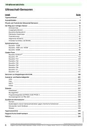
Table of Contents 1FT6<br />
1 Motor Description . . . . . . . . . . . . . . . . . . . . . . . . . . . . . . . . . . . . . . . . . . . . . . 1FT6/1-15<br />
1.1 Applications and features . . . . . . . . . . . . . . . . . . . . . . . . . . . . . . . . . 1FT6/1-15<br />
1.2 Technical design, 1FT6 motor . . . . . . . . . . . . . . . . . . . . . . . . . . . . . 1FT6/1-16<br />
1.3 Technical design, options, supplements . . . . . . . . . . . . . . . . . . . . 1FT6/1-17<br />
1.4 Order designation . . . . . . . . . . . . . . . . . . . . . . . . . . . . . . . . . . . . . . . 1FT6/1-18<br />
1.5 Technical data . . . . . . . . . . . . . . . . . . . . . . . . . . . . . . . . . . . . . . . . . . 1FT6/1-21<br />
1.6 Armature short–circuit braking . . . . . . . . . . . . . . . . . . . . . . . . . . . . 1FT6/1-27<br />
1.7 Cooling . . . . . . . . . . . . . . . . . . . . . . . . . . . . . . . . . . . . . . . . . . . . . . . . 1FT6/1-32<br />
1.7.1 Force ventilation . . . . . . . . . . . . . . . . . . . . . . . . . . . . . . . . . . . . . . . . 1FT6/1-32<br />
1.7.2 Water–cooling . . . . . . . . . . . . . . . . . . . . . . . . . . . . . . . . . . . . . . . . . . 1FT6/1-34<br />
1.8 Electrical connections . . . . . . . . . . . . . . . . . . . . . . . . . . . . . . . . . . . . 1FT6/1-39<br />
1.8.1 Connector assignment . . . . . . . . . . . . . . . . . . . . . . . . . . . . . . . . . . . 1FT6/1-39<br />
1.8.2 Connection, terminal box . . . . . . . . . . . . . . . . . . . . . . . . . . . . . . . . . 1FT6/1-40<br />
1.9 Drive–out coupling . . . . . . . . . . . . . . . . . . . . . . . . . . . . . . . . . . . . . . . 1FT6/1-42<br />
2 Technical Data and Characteristics . . . . . . . . . . . . . . . . . . . . . . . . . . . . . . 1FT6/2-45<br />
2.1 Speed–torque diagrams . . . . . . . . . . . . . . . . . . . . . . . . . . . . . . . . . . 1FT6/2-45<br />
2.1.1 1FT6 series, non–ventilated . . . . . . . . . . . . . . . . . . . . . . . . . . . . . . 1FT6/2-46<br />
2.1.2 1FT6 series, force ventilated . . . . . . . . . . . . . . . . . . . . . . . . . . . . . . 1FT6/2-106<br />
2.1.3 1FT6 series, water cooled . . . . . . . . . . . . . . . . . . . . . . . . . . . . . . . . 1FT6/2-138<br />
2.2 Cantilever force diagrams . . . . . . . . . . . . . . . . . . . . . . . . . . . . . . . . 1FT6/2-172<br />
2.3 Axial forces . . . . . . . . . . . . . . . . . . . . . . . . . . . . . . . . . . . . . . . . . . . . . 1FT6/2-177<br />
3 Motor Components (Options) . . . . . . . . . . . . . . . . . . . . . . . . . . . . . . . . . . . 1FT6/3-179<br />
3.1 Thermal motor protection . . . . . . . . . . . . . . . . . . . . . . . . . . . . . . . . . 1FT6/3-179<br />
3.2 Encoder . . . . . . . . . . . . . . . . . . . . . . . . . . . . . . . . . . . . . . . . . . . . . . . . 1FT6/3-181<br />
3.2.1 Incremental encoders . . . . . . . . . . . . . . . . . . . . . . . . . . . . . . . . . . . . 1FT6/3-182<br />
3.2.2 Absolute value encoder . . . . . . . . . . . . . . . . . . . . . . . . . . . . . . . . . . 1FT6/3-184<br />
3.2.3 Resolver . . . . . . . . . . . . . . . . . . . . . . . . . . . . . . . . . . . . . . . . . . . . . . . 1FT6/3-186<br />
3.3 Holding brake . . . . . . . . . . . . . . . . . . . . . . . . . . . . . . . . . . . . . . . . . . . 1FT6/3-188<br />
3.4 Gearbox . . . . . . . . . . . . . . . . . . . . . . . . . . . . . . . . . . . . . . . . . . . . . . . 1FT6/3-189<br />
3.4.1 Planetary gearbox, 1–stage . . . . . . . . . . . . . . . . . . . . . . . . . . . . . . . 1FT6/3-189<br />
3.4.2 Planetary gearbox, 2–stage . . . . . . . . . . . . . . . . . . . . . . . . . . . . . . . 1FT6/3-191<br />
4 Dimension Drawings . . . . . . . . . . . . . . . . . . . . . . . . . . . . . . . . . . . . . . . . . . . . 1FT6/4-195<br />
4.1 Non–ventilated 1FT6 motors . . . . . . . . . . . . . . . . . . . . . . . . . . . . . . 1FT6/4-196<br />
4.2 Force–ventilated 1FT6 motors . . . . . . . . . . . . . . . . . . . . . . . . . . . . 1FT6/4-205<br />
4.3 Water–cooled 1FT6 motors . . . . . . . . . . . . . . . . . . . . . . . . . . . . . . . 1FT6/4-211<br />
4.4 Cooling water connections for shaft height 60 to 100 . . . . . . . . . 1FT6/4-218<br />
A References . . . . . . . . . . . . . . . . . . . . . . . . . . . . . . . . . . . . . . . . . . . . . . . . . . . . . 1FT6/A-219<br />
Index . . . . . . . . . . . . . . . . . . . . . . . . . . . . . . . . . . . . . . . . . . . . . . . . . . . . . . . . . . Index–223<br />
�<br />
1FT6-14<br />
© Siemens AG 2004 All rights reserved<br />
Synchronous Servomotors, 1FT6 (PFT6) – 02.04 Edition
Motor Description<br />
1.1 Applications and features<br />
Applications<br />
The 1FT6 series was developed for applications on machine tools and production<br />
machines with the highest requirements placed on the smooth running characteristics<br />
and surface quality. In conjunction with the SIMODRIVE and SIMOVERT<br />
MASTERDRIVES MC drive converter systems, these motors are, among other<br />
things, admirably suited for feed and main drives on lathes and milling machines,<br />
machining centers, for grinding and special–purpose machines and for<br />
woodworking.<br />
Features<br />
They can be directly mounted onto feed spindles and onto gearboxes with toothed<br />
wheels or toothed belts.<br />
Depending on the shaft height, the 1FT6 series has stall torques of between 0.4<br />
and 700 Nm and rated speeds from 1500 to 6000 RPM. A high overload capability<br />
is available over the complete speed control range. The motors are optimized for a<br />
low torque ripple.<br />
Standards, regulations<br />
The appropriate standards, regulations are directly assigned to the functional<br />
requirements.<br />
© Siemens AG 2004 All rights reserved<br />
Synchronous Servomotors, 1FT6 (PFT6) – 02.04 Edition<br />
1<br />
1FT6/1-15
Motor Description<br />
1.2 Technical design, 1FT6 motor<br />
1.2 Technical design, 1FT6 motor<br />
Table 1-1 Design features of the standard design<br />
Technical features Design<br />
Machine type Permanent–magnet synchronous servomotor<br />
Type of construction<br />
IM B5 (IM V1, IM V3) for shaft heights 28 to 132<br />
(acc. to EN60034–7;<br />
IM B35 (IM V15, IM V36) for shaft heights 132 to 160<br />
IEC 60034–7)<br />
(options, refer to Table 1-2)<br />
Degree of protection<br />
(acc. to EN60034–5;<br />
IEC 60034–5)<br />
IP 64; core types IP 65 (options, refer to Table 1-2)<br />
Cooling<br />
Non–ventilated<br />
(acc. to EN60034–6;<br />
IEC 60034–6)<br />
2)<br />
Forced cooling 2) 3)<br />
Water–cooling<br />
Thermal motor protection<br />
(acc. to EN 60034–11;<br />
IEC 60034–11)<br />
KTY84 temperature sensor in the stator winding<br />
Shaft end<br />
Cylindrical; without keyway and without key;<br />
(acc. to DIN 748–3; IEC 60072–1) tolerance field k6, (option, refer to Table 1-2)<br />
Radial eccentricity, concentricity Tolerance N (normal)<br />
and axial eccentricity (acc. to<br />
DIN 42955; IEC 60072–1)<br />
(options, refer to Table 1-2)<br />
Vibration severity<br />
Level N (normal)<br />
(acc. to EN 60034–14;<br />
IEC 60034–14)<br />
(options, refer to Table 1-2)<br />
Max. sound pressure level Shaft heights 28 to 100: 72 dB(A) up to n = 2000 RPM<br />
(acc. to EN 21680) + 3 dB Shaft heights 132 to 160: 73 dB(A) up to n = 2000 RPM<br />
Bearings Roller bearings with permanent grease lubrication (lubricated for the<br />
bearing lifetime)<br />
Bearing lifetime: 20000 h<br />
SH 36, 48: Locating bearing on the NDE<br />
Winding insulation<br />
SH 28, 63 up to 160: Locating bearing on the DE<br />
Temperature rise class F<br />
(acc. to EN 60034–1;<br />
for a winding temperature rise of<br />
IEC 60034–1)<br />
∆T = 100 K for an ambient temperature of 40 °C.<br />
Installation altitude<br />
� 1000 m above sea level, otherwise de–rating<br />
(acc. to EN and IEC 60034–1)<br />
2)<br />
2,000 m Factor 0.94<br />
2500 m Factor 0.9<br />
Magnetic material Rare earth material<br />
Electr. connection Power connection via a terminal box or connector<br />
Encoder signal via connector<br />
Integrated speed encoder Optical encoders:<br />
� Incremental encoders sin/cos 1Vpp (I–2048)<br />
� Absolute value encoders EnDat (A–2048 and A–512) 1)<br />
� Resolver, two–pole/multi–pole<br />
Rating plate<br />
For more detailed information, refer to the Chapter Encoders.<br />
A second rating plate is provided for all motors<br />
1) When using the absolute value encoder and non–ventilated or forced ventilation, the rated torque is<br />
reduced by 10 % (refer to the Table, Technical data)<br />
2) De–rating for temperatures > 40 °C and/or installation altitudes > 1000 m refer to the Planning Guide<br />
”General Part for Synchronous Servomotors”<br />
3) Not suitable for conductive dust. Forced ventilation cannot be used in the presence of flammable, corrosive,<br />
electrically conductive or explosive dust.<br />
1FT6/1-16<br />
© Siemens AG 2004 All rights reserved<br />
Synchronous Servomotors, 1FT6 (PFT6) – 02.04 Edition
1.3 Technical design, options, supplements<br />
Table 1-2 Options<br />
Technical features Design<br />
Type of construction<br />
IM B14 for shaft heights 63 to 100<br />
(acc. to EN60034–7;<br />
IEC 60034–7)<br />
Degree of protection<br />
(acc. to EN 60034–5;<br />
IEC 60034–5)<br />
Shaft end<br />
(acc. to EN and IEC 60034–14)<br />
Radial eccentricity, concentricity<br />
and axial eccentricity (acc. to<br />
DIN 42955; IEC 60072–1)<br />
Vibration severity<br />
(acc. to EN 60034–14;<br />
IEC 60034–14)<br />
© Siemens AG 2004 All rights reserved<br />
Synchronous Servomotors, 1FT6 (PFT6) – 02.04 Edition<br />
Motor Description<br />
1.3 Technical design, options, supplements<br />
IP65, IP67, IP68<br />
Information: Shaft height 28 only available in degree of protection<br />
IP64 or IP67.<br />
IP67 and IP68 with sealing air connection.<br />
Force–ventilated motors only available in degree of<br />
protection IP64 and IP65 available (fan IP54).<br />
Cylindrical; with keyway and key;<br />
Tolerance zone k6<br />
H=half–key balancing<br />
Tolerance R (reduced)<br />
Level R (not 1FT6108–8WF7)<br />
Integrated/mounted components Mounted planetary gear for SH 28 to 132 (geared motors only<br />
available with vibration severity level N)<br />
Cable outlet for terminal boxes Outlet direction can be selected in 90� steps<br />
1FT6/1-17
Motor Description<br />
1.4 Order designation<br />
1.4 Order designation<br />
Order designation (standard types) SH 28 to SH 132<br />
(non–ventilated, forced–ventilated and water cooling)<br />
1FT6/1-18<br />
. . . . – . .<br />
Electric motor<br />
Synchronous motor<br />
AC servomotor<br />
Series<br />
Frame size<br />
Length<br />
Number of poles<br />
Type of cooling<br />
A = Non–ventilated<br />
S = Force–ventilated with mounted separately–driven fan<br />
W = Water cooling<br />
Rated speed<br />
B = 1500 RPM<br />
C = 2000 RPM<br />
F = 3000 RPM<br />
Type of construction<br />
H = 4500 RPM<br />
1 = IM B5 (standard)<br />
K = 6000 RPM<br />
2 = IM B14 1 1 F T 6 . – . 7 . . .<br />
)<br />
Connector outlet direction<br />
1 = transverse, right (not for SH 36, 48, 63)<br />
2 = transverse, left (not for SH 36, 48 63)<br />
3 = axial NDE (not for SH 132)<br />
4 = axial DE<br />
Optical encoders<br />
A =Incremental encoders, sin/cos 1V pp (I–2048)<br />
E = Absolute value encoder EnDat (A–2048) from SH 36<br />
H = Absolute value encoder EnDat (A–512) from SH 28<br />
S =Resolvers, multi–pole 4)<br />
T = Resolvers, 2–pole<br />
Shaft end Radial eccentricity Holding brake<br />
A = with key N without<br />
B = with key N with<br />
D = with key R without<br />
E = with key R with<br />
G = smooth shaft N without<br />
H = smooth shaft N with<br />
K = smooth shaft R without<br />
L = smooth shaft R with<br />
Vibration severity level Degree of protection<br />
0 = N IP64<br />
1 = N IP65<br />
2 = N IP67 2)<br />
6 = N IP68 2)<br />
3 = R 3) IP64<br />
4 = R 3) IP65<br />
5 = R 3) IP67 2)<br />
7 = R 3) IP68 2)<br />
1) only for SH 63, 80, 100<br />
2) not for force–ventilated motors<br />
3) not for 1FT6 108–8WF7<br />
4) Pole pair number of the encoder corresponds to that of the motor<br />
© Siemens AG 2004 All rights reserved<br />
Synchronous Servomotors, 1FT6 (PFT6) – 02.04 Edition
Order designation (core types)<br />
Electric motor<br />
Synchronous motor<br />
AC servomotor<br />
Series<br />
Frame size<br />
Length<br />
Identification, core type<br />
Rated speed<br />
C = 2000 RPM<br />
F = 3000 RPM<br />
H = 4500 RPM<br />
K = 6000 RPM<br />
Connector outlet direction<br />
1 = transverse, right (not for SH 48, 63)<br />
2 = transverse, left (not for SH 48, 63)<br />
3 = axial NDE<br />
4 = axial DE<br />
Optical encoders<br />
A =Incremental encoders, sin/cos 1V pp (I–2048)<br />
E =Absolute value encoder EnDat (A–2048) 1)<br />
G = without holding brake<br />
H = with holding brake<br />
© Siemens AG 2004 All rights reserved<br />
Synchronous Servomotors, 1FT6 (PFT6) – 02.04 Edition<br />
Motor Description<br />
1.4 Order designation<br />
1 F T 6 . . . – 1 A . 7 1 – . . . 1<br />
1FT6/1-19
Motor Description<br />
1.4 Order designation<br />
Order designation for<br />
SH 132, water cooling and<br />
SH 160, force ventilated and water–cooled<br />
Electric motor<br />
Synchronous motor<br />
AC servomotor<br />
Series<br />
Number of poles<br />
Type of cooling<br />
S = Force ventilated<br />
W = Water cooling<br />
Rated speed<br />
B = 1500 RPM<br />
D = 2500 RPM<br />
Type of construction<br />
6 = IM B35<br />
Terminal box<br />
5 = Top–mounted terminal box, cable outlet, transverse, right<br />
6 = Top–mounted terminal box, cable outlet, transverse, left<br />
7 = Top–mounted terminal box, cable outlet, axial NDE<br />
8 = Top–mounted terminal box, cable outlet, axial DE<br />
Encoder system<br />
A = Incremental encoders, sin/cos 1 Vpp (I–2048)<br />
E =Absolute value encoders EnDat (A–2048)<br />
S =Resolvers, multi–pole<br />
T = Resolvers, 2–pole<br />
Shaft end<br />
A = Shaft end with keyway, tolerance N, without brake<br />
D = Shaft end with keyway, tolerance R, without brake<br />
G = Smooth shaft end, tolerance N, without brake<br />
K = Smooth shaft end, tolerance R, without brake<br />
Vibration severity level and degree of protection 1)<br />
0 = Vibration severity level N<br />
1 = Vibration severity level N<br />
3 = Vibration severity level R<br />
4 = Vibration severity level R<br />
1FT6/1-20<br />
IP64<br />
IP65<br />
IP64<br />
IP65<br />
1) specified degree of protection, only applies for water cooling;<br />
for air cooling, restriction due to the mounted fan with IP54<br />
1 F T 6 . . . – . . . 7 6 – . . . .<br />
© Siemens AG 2004 All rights reserved<br />
Synchronous Servomotors, 1FT6 (PFT6) – 02.04 Edition
1.5 Technical data<br />
© Siemens AG 2004 All rights reserved<br />
Synchronous Servomotors, 1FT6 (PFT6) – 02.04 Edition<br />
Motor Description<br />
1.5 Technical data<br />
Core types are designated with gray. 100 K values are specified in the table.<br />
Table 1-3 Technical data 1FT6, rated speed 1500 RPM<br />
nN M0 MN MN Motor type I0 IN Connec- Cross–<br />
1)<br />
tor size section<br />
[RPM] [Nm] [Nm] [Nm] 1FT6– [A] [A] 2)<br />
3)<br />
[mm2 Cable type<br />
4) 5)<br />
] 6FX�002– 6)<br />
Terminal<br />
box 2)<br />
Non–ventilated<br />
1500 27.0 24.5 22.05 102–8AB7� 8.7 8.4 1.5 4 x 1.5 5�A21–1��0 gk130<br />
1500 50.0 41.0 36.9 105–8AB7� 16.0 14.5 1.5 4 x 2.5 5�A31–1��0 gk130<br />
1500 70.0 61.0 54.9 108–8AB7� 22.3 20.5 1.5 4 x 4 5�A41–1��0 gk130<br />
1500 75.0 62.0 55.8 132–6AB7� 21.6 19 1.5 4 x 4 5�A41–1��0 gk230<br />
1500 95.0 75.0 67.5 134–6AB7� 27.0 24 1.5 4 x 4 5�A41–1��0 gk230<br />
1500 115.0 88.0 79.2 136–6AB7� 34.0 27 1.5 4 x 10 5�A61–1��0 gk230<br />
Force ventilation<br />
1500 65.0 59.0 53.1 105–8SB7� 21.9 21.7 1.5 4 x 4 5�A41–1��0 gk130<br />
1500 90.0 83.0 74.7 108–8SB7� 30.0 31 1.5 4 x 10 5�A61–1��0 gk130<br />
1500 110.0 102.0 91.8 132–6SB7� 36.0 36 3 4 x 16 5�A23–1��0 gk230<br />
1500 140.0 130.0 117.0 134–6SB7� 44.0 45 3 4 x 16 5�A23–1��0 gk230<br />
1500 175.0 160.0 144.0 136–6SB7� 55.0 55 3 4 x 16 5�A23–1��0 gk420<br />
1500 425 385 347 163–8SB7� 8) 151 136 ––– ––– ––– gk630<br />
1500 600 540 486 168–8SB7� 8) 194 174 ––– ––– ––– gk630<br />
Water–cooling<br />
1500 119.0 116.0 116.0 108–8WB7� 43.0 43 3 4 x 16 5�A23–1��0 gk230<br />
1500 155 150 150 132–6WB7� 8) 58 58 ––– ––– ––– gk630<br />
1500 200 190 190 134–6WB7� 8) 73 67 ––– ––– ––– gk630<br />
1500 240 230 230 136–6WB7� 8) 92 90 ––– ––– ––– gk630<br />
1500 300 290 290 138–6WB7� 8) 112 112 ––– ––– ––– gk630<br />
1500 450 450 450 163–8WB7� 8) 160 160 ––– ––– ––– gk630<br />
1500 700 690 690 168–8WB7� 8) 225 221 ––– ––– ––– gk630<br />
Number<br />
of poles<br />
Cables are not included in the scope of supply of the<br />
motors and must be separately ordered.<br />
without brake cable: with overall shield C<br />
with brake cable: with overall shield D<br />
Lengths 7) 5 m AF<br />
(examples) 10 m BA<br />
15 m BF<br />
18 m BJ<br />
25 m CF<br />
1) With absolute value encoder (due to the max. encoder temperature)<br />
2) Power connector and terminal box mutually exclude each other<br />
3) Motor with terminal box, max. cross–section that can be connected, refer to Table 1-19<br />
4) The shock hazard protection of the power cables depends on the size of the selected power module (refer to the<br />
Planning Guide, Drive Converter)<br />
5) Motor with terminal box, power and signal cable, refer to Catalog, Chapter ”MOTION–CONNECT connection system”<br />
6) 6FX8002 = MOTION–CONNECT 800;<br />
6FX5002 = MOTION–CONNECT 500;<br />
Technical data, refer to Catalog, Chapter ”MOTION–CONNECT connection system”<br />
7) Cables can be supplied in units of one meter;<br />
Length code, refer to the Planning Guide ”General Part for Synchronous Servomotors”<br />
8) For the 1FT613� motors, the maximum current and rated current of the drive converter must be observed.<br />
1FT616� motors can only be operated together with SIMOVERT MASTERDRIVES MC drive converters.<br />
1FT6/1-21
Motor Description<br />
1.5 Technical data<br />
Table 1-4 Technical data 1FT6, rated speed 2000 RPM<br />
nN M0 MN MN [RPM] [Nm] [Nm]<br />
1) Motor type I0 IN Connec- Cross–<br />
tor size section<br />
[Nm] 1FT6– [A] [A] 2)<br />
3)<br />
[mm2 Cable type<br />
4) 5)<br />
] 6FX�002– 6)<br />
Terminal<br />
box 2)<br />
Non–ventilated<br />
2000 4.0 3.7 3.3 061–6AC7� 1.9 1.9 1 4 x 1.5 5�A01–1��0 –––<br />
2000 6.0 5.2 4.6 062–6AC7� 2.7 2.6 1 4 x 1.5 5�A01–1��0 –––<br />
2000 9.5 8.0 7.2 064–6AC7� 4.2 3.8 1 4 x 1.5 5�A01–1��0 –––<br />
2000 8.0 7.5 6.7 081–8AC7� 3.9 4.1 1.5 4 x 1.5 5�A21–1��0 –––<br />
2000 13.0 11.4 10.0 082–8AC7� 6.6 6.6 1.5 4 x 1.5 5�A21–1��0 –––<br />
2000 20.0 16.9 15.2 084–8AC7� 8.8 8.3 1.5 4 x 1.5 5�A21–1��0 –––<br />
2000 27.0 22.5 20.2 086–8AC7� 11.3 10.9 1.5 4 x 1.5 5�A21–1��0 –––<br />
2000 27.0 23.0 20.7 102–�AC7� 12.1 11 1.5 4 x 1.5 5�A21–1��0 gk130<br />
2000 50.0 38.0 34.2 105–�AC7� 21.4 17.6 1.5 4 x 4 5�A41–1��0 gk130<br />
2000 70.0 55.0 49.5 108–8AC7� 29.0 24.5 1.5 4 x 10 5�A61–1��0 gk130<br />
2000 75.0 55.0 49.5 132–6AC7� 29.0 23 1.5 4 x 10 5�A61–1��0 gk230<br />
2000 95.0 65.0 58.5 134–6AC7� 36.0 27 1.5 4 x 10 5�A61–1��0 gk230<br />
2000 115.0 74.0 66.6 136–6AC7� 42.0 30 3 4 x 16 5�A23–1��0 gk230<br />
Force ventilation<br />
2000 65.0 56.0 50.4 105–8SC7� 30.0 28 1.5 4 x 10 5�A61–1��0 gk230<br />
2000 90.0 80.0 72.0 108–8SC7� 41.0 40 3 4 x 16 5�A23–1��0 gk230<br />
2000 110.0 98.0 88.2 132–6SC7� 47.0 46 3 4 x 16 5�A23–1��0 gk420<br />
2000 140.0 125.0 112.5 134–6SC7� 58.0 57 3 4 x 16 5�A23–1��0 gk420<br />
2000 175.0 155.0 139.5 136–6SC7� 77.0 72 3 4 x 25 5DA33–1��0 gk420<br />
Water–cooling<br />
2000 85.0 82.0 82.0 105–8WC7� 58.0 60 3 4 x 16 5�A23–1��0 gk230<br />
2000 119.0 115.0 115.0 108–8WC7� 57.0 57 3 4 x 16 5�A23–1��0 gk230<br />
1FT6/1-22<br />
1 Core type<br />
8 Number of poles<br />
Cables are not included in the scope of supply of the<br />
motors and must be separately ordered.<br />
without brake cable: with overall shield C<br />
with brake cable: with overall shield D<br />
Lengths 7) 5 m AF<br />
(examples) 10 m BA<br />
15 m BF<br />
18 m BJ<br />
25 m CF<br />
1) With absolute value encoder (due to the max. encoder temperature)<br />
2) Power connector and terminal box mutually exclude each other<br />
3) Motor with terminal box, max. cross–section that can be connected, refer to Table 1-19<br />
4) The shock hazard protection of the power cables depends on the size of the selected power module (refer to the<br />
Planning Guide, Drive Converter)<br />
5) Motor with terminal box, power and signal cable, refer to Catalog, Chapter ”MOTION–CONNECT connection system”<br />
6) 6FX8002 = MOTION–CONNECT 800;<br />
6FX5002 = MOTION–CONNECT 500;<br />
Technical data, refer to Catalog, Chapter ”MOTION–CONNECT connection system”<br />
7) Cables can be supplied in units of one meter;<br />
Length code, refer to the Planning Guide ”General Part for Synchronous Servomotors”<br />
© Siemens AG 2004 All rights reserved<br />
Synchronous Servomotors, 1FT6 (PFT6) – 02.04 Edition
Table 1-5 Technical data 1FT6, rated speed 2500 RPM<br />
© Siemens AG 2004 All rights reserved<br />
Synchronous Servomotors, 1FT6 (PFT6) – 02.04 Edition<br />
Motor Description<br />
1.5 Technical data<br />
nN M0 MN MN [RPM] [Nm] [Nm]<br />
1) Motor type I0 IN Connec-<br />
[Nm]<br />
tor size<br />
1FT6– [A] [A] 2 )<br />
Cross–<br />
section3) [mm2 Cable type<br />
4) 5)<br />
] 6FX�002– 6)<br />
Terminal<br />
box 2)<br />
Force ventilation<br />
2500 425 340 306 163–8SD7� 8) 226 185 ––– ––– ––– gk630<br />
Water–cooling<br />
2500 155 135 135 132–6WD7� 8) 92 82 ––– ––– ––– gk630<br />
2500 200 185 185 134–6WD7� 8) 122 115 ––– ––– ––– gk630<br />
2500 240 220 220 136–6WD7� 8) 158 149 ––– ––– ––– gk630<br />
2500 300 275 275 138–6WD7� 8) 167 162 ––– ––– ––– gk630<br />
2500 425 340 340 163–8WD7� 8) 240 240 ––– ––– ––– gk630<br />
Number of poles<br />
Cables are not included in the scope of supply of the motors and must be separately ordered.<br />
1) With absolute value encoder (due to the max. encoder temperature)<br />
2) Power connector and terminal box mutually exclude each other<br />
3) Motor with terminal box, max. cross–section that can be connected, refer to Table 1-19<br />
4) The shock hazard protection of the power cables depends on the size of the selected power module (refer to the<br />
Planning Guide, Drive Converter)<br />
5) Motor with terminal box, power and signal cable, refer to Catalog, Chapter ”MOTION–CONNECT connection system”<br />
6) 6FX8002 = MOTION–CONNECT 800;<br />
6FX5002 = MOTION–CONNECT 500;<br />
Technical data, refer to Catalog, Chapter ”MOTION–CONNECT connection system”<br />
7) Cables can be supplied in units of one meter;<br />
Length code, refer to the Planning Guide ”General Part for Synchronous Servomotors”<br />
8) For the 1FT613� motors, the maximum current and rated current of the drive converter must be observed.<br />
1FT616� motors can only be operated together with SIMOVERT MASTERDRIVES MC drive converters.<br />
1FT6/1-23
Motor Description<br />
1.5 Technical data<br />
Table 1-5 Technical data 1FT6, rated speed 3000 RPM<br />
nN M0 MN MN [RPM] [Nm] [Nm]<br />
1) Motor type I0 IN Connec- Cross–<br />
tor size section<br />
[Nm] 1FT6– [A] [A] 2)<br />
3)<br />
[mm2 Cable type<br />
4) 5)<br />
] 6FX�002– 6)<br />
Terminal<br />
box 2)<br />
Non–ventilated<br />
3000 2.6 2.15 2.0 041–4AF7� 1.9 1.7 1 4 x 1.5 5�A01–1��0 –––<br />
3000 5.0 4.3 4.1 044–�AF7� 3.0 2.9 1 4 x 1.5 5�A01–1��0 –––<br />
3000 4.0 3.5 3.3 061–6AF7� 2.7 2.6 1 4 x 1.5 5�A01–1��0 –––<br />
3000 6.0 4.7 4.5 062–�AF7� 4.1 3.4 1 4 x 1.5 5�A01–1��0 –––<br />
3000 9.5 7.0 6.7 064–�AF7� 6.1 4.9 1 4 x 1.5 5�A01–1��0 –––<br />
3000 8.0 6.9 6.6 081–8AF7� 5.8 5.6 1.5 4 x 1.5 5�A21–1��0 –––<br />
3000 13.0 10.3 9.8 082–�AF7� 9.6 8.7 1.5 4 x 1.5 5�A21–1��0 –––<br />
3000 20.0 14.7 14.0 084–�AF7� 13.2 11 1.5 4 x 1.5 5�A21–1��0 –––<br />
3000 27.0 18.5 17.6 086–�AF7� 16.4 13 1.5 4 x 2.5 5�A31–1��0 –––<br />
3000 27.0 19.5 18.5 102–8AF7� 16.9 13.2 1.5 4 x 2.5 5�A31–1��0 gk130<br />
3000 50.0 31.0 29.0 105–8AF7� 32.0 22.5 1.5 4 x 10 5�A61–1��0 gk130<br />
3000 70.0 37.0 33.3 108–8AF7� 41.0 25 3 4 x 16 5�A23–1��0 gk230<br />
3000 75.0 36.0 34.2 132–6AF7� 43.0 23 3 4 x 16 5�A23–1��0 gk230<br />
Force ventilation<br />
3000 26.0 22.0 21.0 084–8SF7� 18.2 17 1.5 4 x 2.5 5�A31–1��0 –––<br />
3000 35.0 31.0 29.0 086–8SF7� 25.0 24.5 1.5 4 x 4 5�A41–1��0 –––<br />
3000 65.0 50.0 48.0 105–8SF7� 42.0 35 3 4 x 16 5�A23–1��0 gk230<br />
3000 90.0 70.0 63.0 108–8SF7� 62.0 53 3 4 x 16 5�A23–1��0 gk420<br />
3000 110.0 90.0 81.0 132–6SF7� 69.0 62 3 4 x 25 5DA33–1��0 gk420<br />
3000 140.0 110.0 99.0 134–6SF7� 83.0 72 3 4 x 35 5DA43–1��0 gk420<br />
3000 175.0 145.0 130.5 136–6SF7� 110.0 104 ––– ––– ––– gk420<br />
Water–cooling<br />
3000 10.2 10.1 10.1 062–6WF7� 6.9 6.9 1 4 x 1.5 5�A01–1��0 –––<br />
3000 16.2 16.1 16.1 064–6WF7� 10.3 10.3 1 4 x 1.5 5�A01–1��0 –––<br />
3000 35.0 35.0 35.0 084–8WF7� 24.5 27 1.5 4 x 4 5�A41–1��0 –––<br />
3000 47.0 46.0 46.0 086–8WF7� 34.0 37 1.5 4 x 10 5�A61–1��0 –––<br />
3000 85.0 78.0 78.0 105–8WF7� 83.0 82 3 4 x 35 5DA43–1��0 gk420<br />
3000 119.0 109.0 109.0 108–8WF7� 86.0 81 3 4 x 35 5DA43–1��0 gk420<br />
1FT6/1-24<br />
1 Core type<br />
4, 6, 8 No. of poles<br />
Cables are not included in the scope of supply of the motors and<br />
must be separately ordered. Footnotes, refer to the next page.<br />
without brake cable: with overall shield C<br />
with brake cable: with overall shield D<br />
Lengths 7) 5 m AF<br />
(examples) 10 m BA<br />
15 m BF<br />
18 m BJ<br />
25 m CF<br />
© Siemens AG 2004 All rights reserved<br />
Synchronous Servomotors, 1FT6 (PFT6) – 02.04 Edition
Table 1-6 Technical data 1FT6, rated speed 4500 RPM<br />
© Siemens AG 2004 All rights reserved<br />
Synchronous Servomotors, 1FT6 (PFT6) – 02.04 Edition<br />
Motor Description<br />
1.5 Technical data<br />
nN M0 MN MN [RPM] [Nm] [Nm]<br />
1) Motor type I0 IN Connec- Cross–<br />
tor size section<br />
[Nm] 1FT6– [A] [A] 2)<br />
3)<br />
[mm2 Cable type<br />
4) 5)<br />
] 6FX�002– 6)<br />
Terminal<br />
box 2)<br />
Non–ventilated<br />
4500 4.0 2.9 2.6 061–6AH7� 4.0 3.4 1 4 x 1.5 5�A01–1��0 –––<br />
4500 6.0 3.6 3.2 062–�AH7� 5.7 3.9 1 4 x 1.5 5�A01–1��0 –––<br />
4500 9.5 4.8 4.3 064–�AH7� 9.0 5.5 1 4 x 1.5 5�A01–1��0 –––<br />
4500 8.0 5.8 5.2 081–8AH7� 8.6 7.3 1.5 4 x 1.5 5�A21–1��0 –––<br />
4500 13.0 8.5 7.7 082–�AH7� 14.8 11 1.5 4 x 1.5 5�A21–1��0 –––<br />
4500 20.0 10.5 9.5 084–�AH7� 19.8 12.5 1.5 4 x 4 5�A41–1��0 –––<br />
4500 27.0 12.0 10.8 086–�AH7� 23.3 12.6 1.5 4 x 4 5�A41–1��0 –––<br />
4500 27.0 12.0 10.8 102–8AH7� 24.1 12 1.5 4 x 4 5�A41–1��0 gk130<br />
Force ventilation<br />
4500 26.0 20.0 18.0 084–8SH7� 26.0 24.5 1.5 4 x 4 5�A41–1��0 –––<br />
4500 35.0 27.0 24.3 086–8SH7� 38.0 32 3 4 x 16 5�A23–1��0 –––<br />
4500 65.0 40.0 36.0 105–8SH7� 59.0 41 3 4 x 16 5�A23–1��0 gk420<br />
Water–cooling<br />
4500 10.2 10.0 10.0 062–6WH7� 9.7 9.6 1 4 x 1.5 5�A01–1��0 –––<br />
4500 16.2 16.0 16.0 064–6WH7� 15.4 15.2 1 4 x 2.5 5�A11–1��0 –––<br />
4500 35.0 35.0 35.0 084–8WH7� 37.0 39 1.5 4 x 10 5�A61–1��0 –––<br />
4500 47.0 45.0 45.0 086–8WH7� 52.0 53 3 4 x 16 5�A23–1��0 –––<br />
1 Core type<br />
6, 8 No. of poles<br />
Cables are not included in the scope of supply of the motors and<br />
must be separately ordered.<br />
without brake cable: with overall shield C<br />
with brake cable: with overall shield D<br />
Lengths 7) 5 m AF<br />
(examples) 10 m BA<br />
15 m BF<br />
18 m BJ<br />
25 m CF<br />
1) With absolute value encoder (due to the max. encoder temperature)<br />
2) Power connector and terminal box mutually exclude each other<br />
3) Motor with terminal box, max. cross–section that can be connected, refer to Table 1-19<br />
4) The shock hazard protection of the power cables depends on the size of the selected power module (refer to the<br />
Planning Guide, Drive Converter)<br />
5) Motor with terminal box, power and signal cable, refer to Catalog, Chapter ”MOTION–CONNECT connection system”<br />
6) 6FX8002 = MOTION–CONNECT 800;<br />
6FX5002 = MOTION–CONNECT 500;<br />
Technical data, refer to Catalog, Chapter ”MOTION–CONNECT connection system”<br />
7) Cables can be supplied in units of one meter;<br />
Length code, refer to the Planning Guide ”General Part for Synchronous Servomotors”<br />
1FT6/1-25
Motor Description<br />
1.5 Technical data<br />
Table 1-7 Technical data 1FT6, rated speed 6000 RPM<br />
nN M0 MN MN [RPM] [Nm] [Nm]<br />
1) Motor type I0 IN Connec- Cross–<br />
tor size section<br />
[Nm] 1FT6– [A] [A] 2)<br />
3)<br />
[mm2 Cable type<br />
4) 5)<br />
] 6FX�002– 6)<br />
Terminal<br />
box 2)<br />
Non–ventilated<br />
6000 0.4 0.3 0.22 021–6AK71 1.25 1.1 1 4 x 1.5 5�A01–1��0 –––<br />
6000 0.8 0.5 0.37 024–6AK71 1.25 0.9 1 4 x 1.5 5�A01–1��0 –––<br />
6000 1.0 0.75 0.6 031–4AK71 1.4 1.2 1 4 x 1.5 5�A01–1��0 –––<br />
6000 2.0 1.4 1.2 034–�AK71 2.6 2.1 1 4 x 1.5 5�A01–1��0 –––<br />
6000 2.6 1.7 1.4 041–4AK71 3.0 2.4 1 4 x 1.5 5�A01–1��0 –––<br />
6000 5.0 3.0 2.6 044–4AK71 5.9 4.1 1 4 x 1.5 5�A01–1��0 –––<br />
6000 4.0 2.1 1.8 061–6AK7� 5.0 3.1 1 4 x 1.5 5�A01–1��0 –––<br />
6000 6.0 2.1 1.8 062–6AK7� 7.6 3.2 1 4 x 1.5 5�A01–1��0 –––<br />
6000 9.5 2.1 1.8 064–6AK7� 12.0 3.5 1 4 x 1.5 5�A01–1��0 –––<br />
6000 8.0 4.6 3.9 081–8AK7� 11.1 7.7 1.5 4 x 1.5 5�A21–1��0 –––<br />
6000 13.0 5.5 4.7 082–8AK7� 17.3 9.1 1.5 4 x 2.5 5�A31–1��0 –––<br />
6000 20.0 6.5 5.5 084–�AK7� 24.1 9.2 1.5 4 x 4 5�A41–1��0 –––<br />
Force ventilation<br />
6000 26.0 17.0 14.5 084–8SK7� 35.0 25.5 1.5 4 x 10 5�A61–1��0 –––<br />
6000 35.0 22.0 18.7 086–8SK7� 44.0 29.0 3 4 x 16 5�A23–1��0 –––<br />
Water–cooling<br />
6000 10.2 9.8 9.8 062–6WK7� 12.9 12.7 1 4 x 1.5 5�A01–1��0 –––<br />
6000 16.2 15.8 15.8 064–6WK7� 20.5 20 1 4 x 2.5 5�A11–1��0 –––<br />
6000 35.0 34.0 34.0 084–8WK7� 47.0 51 3 4 x 16 5�A23–1��0 –––<br />
6000 47.0 44.0 44.0 086–8WK7� 59.0 58 3 4 x 16 5�A23–1��0 –––<br />
1FT6/1-26<br />
1 Core type<br />
4, 8 No. of poles<br />
Cables are not included in the scope of supply of the motors and<br />
must be separately ordered.<br />
without brake cable: with overall shield C<br />
with brake cable: with overall shield D<br />
Lengths 7) 5 m AF<br />
(examples) 10 m BA<br />
15 m BF<br />
18 m BJ<br />
25 m CF<br />
1) With absolute value encoder (due to the max. encoder temperature)<br />
2) Power connector and terminal box mutually exclude each other<br />
3) Motor with terminal box, max. cross–section that can be connected, refer to Table 1-19<br />
4) The shock hazard protection of the power cables depends on the size of the selected power module (refer to the<br />
Planning Guide, Drive Converter)<br />
5) Motor with terminal box, power and signal cable, refer to Catalog, Chapter ”MOTION–CONNECT connection system”<br />
6) 6FX8002 = MOTION–CONNECT 800;<br />
6FX5002 = MOTION–CONNECT 500;<br />
Technical data, refer to Catalog, Chapter ”MOTION–CONNECT connection system”<br />
7) Cables can be supplied in units of one meter;<br />
Length code, refer to the Planning Guide ”General Part for Synchronous Servomotors”<br />
© Siemens AG 2004 All rights reserved<br />
Synchronous Servomotors, 1FT6 (PFT6) – 02.04 Edition
1.6 Armature short–circuit braking<br />
Non–ventilated<br />
© Siemens AG 2004 All rights reserved<br />
Synchronous Servomotors, 1FT6 (PFT6) – 02.04 Edition<br />
Motor Description<br />
1.6 Armature short–circuit braking<br />
For a definition, refer to the Planning Guide ”General Part for Synchronous<br />
Servomotors”.<br />
Braking resistors<br />
The correct dimensioning ensures an optimum braking time. The braking torques<br />
that are obtained are also listed in the tables. Data is valid for braking from the<br />
rated speed. If the drive is braked from another speed, then the braking time<br />
cannot be proportionally reduced. However, longer braking times cannot occur.<br />
The quantities list in the following table are calculated for nominal values according<br />
to the data sheet. The natural variance in production as well as iron saturation<br />
have not been taken into account here. Higher currents and torques can occur<br />
than those calculated as a result of the saturation.<br />
The ratings of the resistors must match the particularr I 2 t load capability, refer to<br />
the Planning Guide ”General Part for Synchronous Servomotors”.<br />
Table 1-8 Resistor braking for the 1FT6 series, shaft heights 28 to 48, non–ventilated<br />
Motor type External<br />
brake<br />
resistor<br />
Ropt [Ω]<br />
SH 28, SH 36, SH 48, non–ventilated<br />
Average braking torque<br />
M br rms [Nm]<br />
without<br />
external brake<br />
resistor<br />
with<br />
external brake<br />
resistor<br />
Max.<br />
braking<br />
torque<br />
Mbr max [Nm]<br />
RMS braking current<br />
I br rms [A]<br />
without<br />
external brake<br />
resistor<br />
with<br />
external brake<br />
resistor<br />
1FT6021–6AK7� – 1.1 – 1.6 6.8 –<br />
1FT6024–6AK7� – 2.7 – 3.7 8.3 –<br />
1FT6031–4AK7� 4.4 2.1 2.3 2.8 6.9 6.4<br />
1FT6034–4AK7� 3.7 3.6 4.4 5.5 13 12<br />
1FT6041–4AF7� 0.31 6.7 6.8 8.4 10 10<br />
1FT6041–4AK7� 2.6 5.8 6.8 8.4 18 17<br />
1FT6044–4AF7� 2.0 13 14 17 18 17<br />
1FT6044–4AK7� 1.8 10 14 17 37 33<br />
1FT6/1-27
Motor Description<br />
1.6 Armature short–circuit braking<br />
Table 1-9 Resistor braking for the 1FT6 series, shaft heights 63 to 80, non–ventilated<br />
Motor type External<br />
brake<br />
resistor<br />
Ropt [Ω]<br />
SH 63 non–ventilated<br />
1FT6/1-28<br />
Average braking torque<br />
M br rms [Nm]<br />
without<br />
external brake<br />
resistor<br />
with<br />
external brake<br />
resistor<br />
Max.<br />
braking<br />
torque<br />
Mbr max [Nm]<br />
RMS braking current<br />
I br rms [A]<br />
without<br />
external brake<br />
resistor<br />
with<br />
external brake<br />
resistor<br />
1FT6061–6AC7� 9.2 3.2 3.6 4.5 4.0 3.7<br />
1FT6061–6AF7� 9.4 2.7 3.6 4.5 5.7 5.2<br />
1FT6061–6AH7� 7.3 2.2 3.6 4.5 8.7 7.8<br />
1FT6061–6AK7� 7.1 1.8 3.6 4.5 10 9.3<br />
1FT6062–6AC7� 7.7 4.7 5.7 7.0 5.9 5.4<br />
1FT6062–6AF7� 6.4 4.0 5.7 7.0 9.0 8.1<br />
1FT6062–6AH7� 5.5 3.2 5.7 7.0 13 11<br />
1FT6062–6AK7� 4.4 2.6 5.7 7.0 17 15<br />
1FT6064–6AC7� 5.9 6.8 9.1 11 9.3 8.5<br />
1FT6064–6AF7� 5.0 5.5 9.1 11 14 12<br />
1FT6064–6AH7� 3.6 4.4 9.1 11 20 18<br />
1FT6064–6AK7� 2.9 3.6 9.1 11 27 24<br />
SH 80 non–ventilated<br />
1FT6081–8AC7� 6.5 5.1 6.9 8.6 7.8 7.1<br />
1FT6081–8AF7� 5.1 4.1 6.9 8.6 12 11<br />
1FT6081–8AH7� 3.7 3.2 6.9 8.6 18 16<br />
1FT6081–8AK7� 3.4 2.4 6.9 8.6 21 19<br />
1FT6082–8AC7� 4.2 6.0 11 13 13 11<br />
1FT6082–8AF7� 3.2 5.8 11 13 19 17<br />
1FT6082–8AH7� 2.4 3.9 11 13 27 24<br />
1FT6082–8AK7� 2.2 3.8 11 13 35 31<br />
1FT6084–8AC7� 3.5 11 18 22 19 17<br />
1FT6084–8AF7� 2.6 8.2 18 22 28 25<br />
1FT6084–8AH7� 1.7 6.8 18 22 44 39<br />
1FT6084–8AK7� 1.7 4.7 18 22 49 44<br />
1FT6086–8AC7� 2.7 15 27 34 26 23<br />
1FT6086–8AF7� 2.1 12 27 34 38 34<br />
1FT6086–8AH7� 1.6 10 27 34 57 51<br />
© Siemens AG 2004 All rights reserved<br />
Synchronous Servomotors, 1FT6 (PFT6) – 02.04 Edition
© Siemens AG 2004 All rights reserved<br />
Synchronous Servomotors, 1FT6 (PFT6) – 02.04 Edition<br />
Motor Description<br />
1.6 Armature short–circuit braking<br />
Table 1-10 Resistor braking for the 1FT6 series, shaft heights 100 to 132, non–ventilated<br />
Motor type External<br />
brake<br />
resistor<br />
Ropt [Ω]<br />
SH 100 non–ventilated<br />
Average braking torque<br />
M br rms [Nm]<br />
without<br />
external brake<br />
resistor<br />
with<br />
external brake<br />
resistor<br />
Max.<br />
braking<br />
torque<br />
Mbr max [Nm]<br />
RMS braking current<br />
I br rms [A]<br />
without<br />
external brake<br />
resistor<br />
with<br />
external brake<br />
resistor<br />
1FT6102–8AB7� 3.9 13 24 30 18 16<br />
1FT6102–8AC7� 2.8 11 24 30 25 23<br />
1FT6102–8AF7� 2.3 8.1 24 30 35 31<br />
1FT6102–8AH7� 1.7 6.5 24 30 51 46<br />
1FT6105–8AB7� 2.2 21 43 54 33 29<br />
1FT6105–8AC7� 1.7 17 43 54 44 39<br />
1FT6105–8AF7� 1.2 13 43 54 65 58<br />
1FT6108–8AB7� 1.4 32 71 88 53 47<br />
1FT6108–8AC7� 1.2 26 71 88 68 61<br />
1FT6108–8AF7� 0.9 21 71 88 99 89<br />
SH 132 non–ventilated<br />
1FT6132–6AB7� 1.0 1) 37 83 105 56 50<br />
1FT6132–6AC7� 1.2 1) 32 83 105 75 67<br />
1FT6132–6AF7� 0.8 1) 23 83 105 110 100<br />
1FT6134–6AB7� 1.2 1) 47 110 140 72 65<br />
1FT6134–6AC7� 0.9 1) 40 110 140 99 89<br />
1FT6136–6AB7� 0.9 1) 55 130 170 91 82<br />
1FT6136–6AC7� 0.8 1) 45 130 170 115 105<br />
1) When utilized according to M 0 (100 K) a series braking resistor must be used in order to<br />
prevent partial de–magnetization.<br />
When utilized according to M 0 (60 K), the additional braking resistor is not required.<br />
1FT6/1-29
Motor Description<br />
1.6 Armature short–circuit braking<br />
Force ventilation<br />
Table 1-11 Resistor braking for the 1FT6 series, force–ventilated<br />
Motor type External<br />
brake<br />
resistor<br />
Ropt [Ω]<br />
1FT6/1-30<br />
Average braking torque<br />
M br rms [Nm]<br />
without<br />
external brake<br />
resistor<br />
with<br />
external brake<br />
resistor<br />
Max.<br />
braking<br />
torque<br />
Mbr max [Nm]<br />
RMS braking current<br />
I br rms [A]<br />
without<br />
external brake<br />
resistor<br />
with<br />
external brake<br />
resistor<br />
SH 80, force ventilated<br />
1FT6084–8SF7� 2.3 8.1 18 22 29 26<br />
1FT6084–8SH7� 1.7 6.8 18 22 44 39<br />
1FT6084–8SK7� 1.4 4.7 18 22 54 48<br />
1FT6086–8SF7� 1.6 11 27 34 42 38<br />
1FT6086–8SH7� 1.1 7.5 27 34 61 55<br />
1FT6086–8SK7�<br />
SH 100, force ventilated<br />
1.1 6.6 27 34 74 66<br />
1FT6105–8SB7� 2.0 21 44 55 35 31<br />
1FT6105–8SC7� 1.5 17 44 55 47 42<br />
1FT6105–8SF7� 1.2 13 44 55 65 58<br />
1FT6105–8SH7� 0.9 10 44 55 96 86<br />
1FT6108–8SB7� 1.2 33 71 88 58 52<br />
1FT6108–8SC7� 0.9 27 71 88 77 69<br />
1FT6108–8SF7�<br />
SH 132, force ventilated<br />
0.6 20 71 88 115 103<br />
1FT6132–6SB7� 1.2 36 1) 83 105 63 57<br />
1FT6132–6SC7� 1.0 30 1) 83 105 83 74<br />
1FT6132–6SF7� 0.7 23 1) 83 105 120 110<br />
1FT6134–6SB7� 0.9 49 1) 110 140 81 73<br />
1FT6134–6SC7� 0.8 40 1) 110 140 105 95<br />
1FT6134–6SF7� 0.6 30 1) 110 140 150 140<br />
1FT6136–6SB7� 0.8 54 1) 130 170 99 88<br />
1FT6136–6SC7� 0.6 43 1) 130 170 130 120<br />
1FT6136–6SF7� 0.5 33 1) SH 160, force ventilated<br />
130 170 190 170<br />
1FT6163–8SB7� 0.3 2) – 380 490 – 270<br />
1FT6163–8SD7� 0.25 2) – 380 490 – 390<br />
1FT6168–8SB7� 0.27 2) – 530 680 – 340<br />
1) When utilized according to M0 (100 K) a series braking resistor must be used in order to<br />
prevent partial de–magnetization. When utilized according to M0 (60 K), the additional braking resistor is not required.<br />
2) In order to prevent that the motors are de–magnetized, when short–circuit braking from the rated speed, the above<br />
specified supplementary resistors must be connected in series.<br />
© Siemens AG 2004 All rights reserved<br />
Synchronous Servomotors, 1FT6 (PFT6) – 02.04 Edition
Water–cooling<br />
Table 1-12 Resistor braking for the 1FT6 series, water cooling<br />
Motor type External<br />
brake<br />
resistor<br />
Ropt [Ω]<br />
Average braking torque<br />
M br rms [Nm]<br />
without<br />
external brake<br />
resistor<br />
© Siemens AG 2004 All rights reserved<br />
Synchronous Servomotors, 1FT6 (PFT6) – 02.04 Edition<br />
with<br />
external brake<br />
resistor<br />
Motor Description<br />
1.6 Armature short–circuit braking<br />
Max.<br />
braking<br />
torque<br />
Mbr max [Nm]<br />
RMS braking current<br />
I br rms [A]<br />
without<br />
external brake<br />
resistor<br />
with<br />
external brake<br />
resistor<br />
SH 60, water cooling<br />
1FT6062–6WF7� 6.4 4.0 5.7 7.0 9 8.1<br />
1FT6062–6WH7� 5.5 3.2 5.7 7.0 13 11<br />
1FT6062–6WK7� 4.4 2.6 5.7 7.0 17 15<br />
1FT6064–6WF7� 5.0 5.5 9.1 11 14 12<br />
1FT6064–6WH7� 3.6 4.4 9.1 11 20 18<br />
1FT6064–6WK7� 2.9 3.6 9.1 11 27 24<br />
SH 80, water cooling<br />
1FT6084–8WF7� 2.3 8.1 18 22 29 26<br />
1FT6084–8WH7� 1.6 6.5 18 22 44 40<br />
1FT6084–8WK7� 1.4 4.7 18 22 54 48<br />
1FT6086–8WF7� 1.6 11 27 34 42 38<br />
1FT6086–8WH7� 1.1 7.5 27 34 61 55<br />
1FT6086–8WK7� 1.1 6.6 27 34 74 66<br />
SH 100, water cooling<br />
1FT6105–�WC7� 0.8 17 44 55 65 58<br />
1FT6105–�WF7� 0.6 14 44 55 96 86<br />
1FT6108–�WB7� 1.2 33 71 88 58 52<br />
1FT6108–�WC7� 0.9 27 71 88 77 69<br />
1FT6108–�WF7� 0.6 21 71 88 115 103<br />
SH 132, water cooling<br />
1FT6132–6WB7� 0.9 40 1) 85 105 72 65<br />
1FT6132–6WD7� 0.7 27 1) 85 105 115 100<br />
1FT6134–6WB7� 0.7 47 1) 110 140 92 82<br />
1FT6134–6WD7� 0.5 33 1) 110 140 150 140<br />
1FT6136–6WB7� 0.6 56 1) 130 170 115 100<br />
1FT6136–6WD7� 0.35 40 1) 130 170 200 180<br />
1FT6138–6WB7� 0.42 69 1) 170 220 150 140<br />
1FT6138–6WD7� 0.32 50 1) 170 220 240 210<br />
SH 160, water cooling<br />
1FT6163–8WB7� 0.3 2) – 380 490 – 270<br />
1FT6163–8WD7� 0.25 2) – 380 490 – 390<br />
1FT6168–8WB7� 0.27 2) – 530 680 – 340<br />
1) When utilized according to M0 (100 K) a series braking resistor must be used in order to<br />
prevent partial de–magnetization. When utilized according to M0 (60 K), the additional braking resistor is not required.<br />
2) It is absolutely prohibited to short–circuit the winding when using smaller supplementary resistors than those specified.<br />
When braking from the rated speed, the resistors listed prevent partial de–magnetization of the rotor.<br />
1FT6/1-31
Motor Description<br />
1.7 Cooling<br />
1.7 Cooling<br />
Cooling types<br />
The different cooling types are defined in the Planning Guide ”General Part for<br />
Synchronous Servomotors”.<br />
1.7.1 Force ventilation<br />
!<br />
1FT6/1-32<br />
Degree of protection IP54 (acc. to EN 60529).<br />
The degrees of protection IP64, IP65, IP67 and IP68 cannot be fulfilled.<br />
The hot discharged air may not be drawn–in again.<br />
Caution<br />
Forced ventilation cannot be used in the presence of flammable, corrosive,<br />
electrically conductive or explosive dust.<br />
Force ventilation, SH 80 and SH 100<br />
Airflow direction from NDE to DE<br />
If the airflow direction is reversed, the torque yield is reduced by approx. 20 %.<br />
Mechanical changes to the motors with respect to the non–ventilated design:<br />
� The power connector is 12 mm higher.<br />
� A sheet metal jacket is shifted over the motor enclosure from the non–drive<br />
end; an axial fan is mounted in this jacket. There is a cut–out in the sheet metal<br />
jacket at the connector positions. This means that the motor is only partially<br />
cooled by the air flow (three–sided ventilation).<br />
� The motor dimensions should be taken from the dimension drawings.<br />
Connection: Connector, Size 1, Order No.: 6FX2003–0CA10<br />
Supply voltage: 1–ph. 230/260 V AC, 50/60 Hz<br />
Maximum current: 0.3 A<br />
Connector assignment for fan connections,<br />
SH 80 and SH 100<br />
5 1<br />
6<br />
4<br />
2<br />
L1<br />
N<br />
© Siemens AG 2004 All rights reserved<br />
Synchronous Servomotors, 1FT6 (PFT6) – 02.04 Edition
© Siemens AG 2004 All rights reserved<br />
Synchronous Servomotors, 1FT6 (PFT6) – 02.04 Edition<br />
Motor Description<br />
1.7 Cooling<br />
Force ventilated, SH 132<br />
Air flow direction from ND to NDE.<br />
The air is blow through the enclosure corners of the extruded profile using a<br />
mounted radial fan.<br />
Connection: Through the terminal box<br />
Supply voltage: 3–ph. 400/480 V AC, 50/60 Hz<br />
Maximum current: 0.4 A<br />
Force ventilated, SH 160<br />
Air flow direction from ND to NDE.<br />
The air is blow through the enclosure corners of the extruded profile using a<br />
mounted radial fan.<br />
Connection: Through the terminal box<br />
Supply voltage: 3–ph. 400/480 V AC, 50/60 Hz<br />
Maximum current: 0.8 A<br />
Minimum clearance between parts and components mounted by the customer and the<br />
air discharge opening<br />
The following minimum clearance must be maintained between parts and components<br />
mounted by the customer and the air discharge opening:<br />
Table 1-13 Minimum clearance to parts and components<br />
mounted by the customer<br />
Shaft height [mm] Minimum clearance [mm]<br />
80 20<br />
100 30<br />
132 60<br />
160 80<br />
1FT6/1-33
Motor Description<br />
1.7 Cooling<br />
1.7.2 Water–cooling<br />
Cooling circuit<br />
1FT6/1-34<br />
The power loss generated by the motor is dissipated using the water cooling. The<br />
machinery construction company must connect–up a cooling system (e.g. heat<br />
exchanger).<br />
The motor rated torques, specified in the data sheets apply for water–cooled<br />
operational and a water intake temperature of < 30 °C.<br />
Notice<br />
If the motor is operated without water cooling, then the rated motor torque is<br />
reduced as a function of the heat losses which can be dissipated by convection<br />
and radiation. In this case, the data for non–ventilated operations apply.<br />
Note<br />
It is not possible to retrofit water cooling.<br />
The cooling medium must be pre–cleaned and filtered in order to prevent the<br />
cooling circuit from becoming blocked. The maximum permissible particle size<br />
after filtering 100 µm.<br />
Notice<br />
If current is flowing through the motor, then the cooling circuit must be activated.<br />
Table 1-14 Technical data for the cooling circuit<br />
Motor type Water flow rate [l] Max. permissible<br />
pressure [bar]<br />
Flow rate [l/min]<br />
1FT6062 0.2 2.5 5<br />
1FT6064 0.26 2.5 5<br />
1FT6082 0.4 2.5 5<br />
1FT6084 0.5 2.5 5<br />
1FT6086 0.6 2.5 5<br />
1FT6105 1.1 2.5 5<br />
1FT6108 1.5 2.5 5<br />
1FT6132 2.1 6.0 8<br />
1FT6134 2.4 6.0 8<br />
1FT6136 2.7 6.0 8<br />
1FT6138 3.1 6.0 8<br />
1FT6163 4.7 6.0 10<br />
1FT6168 5.7 6.0 10<br />
Pressure drop, intake/return: < 0.1 bar<br />
© Siemens AG 2004 All rights reserved<br />
Synchronous Servomotors, 1FT6 (PFT6) – 02.04 Edition
© Siemens AG 2004 All rights reserved<br />
Synchronous Servomotors, 1FT6 (PFT6) – 02.04 Edition<br />
Motor Description<br />
1.7 Cooling<br />
Materials used in the cooling circuits<br />
The anti–corrosion additives used should be harmonized with the cooling system<br />
manufacturer – i.e. the materials of the motor cooler and the materials of the fittings<br />
and cooling medium hoses listed in Table 1-15.<br />
Table 1-15 Materials used in the motor cooling circuit<br />
Motor type Bearing end<br />
shield<br />
1FT606�<br />
Enclosure Sealing agent Connection<br />
plate<br />
1FT608� Aluminum Aluminum Terostat Stainless steel<br />
1FT610�<br />
1FT613� Gray cast iron Aluminum Terostat –––<br />
1FT616�<br />
Cooling medium and anti–corrosion protection<br />
Notice<br />
It is not permissible that ice forms in the cooling circuit, neither in operation nor<br />
during storage.<br />
The checking and change intervals for the cooling medium should be harmonized<br />
with the anti–corrosion agent company and the cooling system manufacturer.<br />
We recommend that an anti–corrosion agent is added to water as cooling–medium<br />
(e.g. Antifrogen N from the Hoechst Company or Tyfocor from Tyforop Chemie<br />
GmbH, refer to Table 1-16).<br />
Observe the specifications of the anti–corrosion agent manufacturer regarding the<br />
ratios of water to anti–corrosion agent<br />
For Tyfocor, the ratio of 75 % water and 25 % anti–corrosion agent should not be<br />
exceeded.<br />
When using another cooling medium (e.g. oil, cooling–lubricating medium) de–<br />
rating may be required in order that the thermal motor limit is not exceeded. The<br />
de–rating can be determined using the following data:<br />
Specific gravity: ρ [kg/m 3 ]<br />
Specific thermal capacitance: cp [J/(kg K)]<br />
Intake temperature: tv [°C]<br />
Flow quantity: v [l/min]<br />
The inquiry must be made in the manufacturer’s plant (Hotline).<br />
The motor power still does not have to be reduced for oil – water mixtures with less<br />
than 10 %.<br />
1FT6/1-35
Motor Description<br />
1.7 Cooling<br />
1FT6/1-36<br />
Note<br />
Different anti–corrosion agents should not be mixed.<br />
Table 1-16 Manufacturers of chemical additives<br />
Company Address Telephone/URL<br />
Tyforop Chemie GmbH Hellbrookstr. 5a,<br />
D–22305 Hamburg<br />
URL: www.tyfo.de<br />
Joh.A. Beckiser<br />
Wassertechnik GmbH<br />
CINCINATI CIMCOOL<br />
Cincinnati Milacron b. v. /<br />
Cimcool Division<br />
Bergstr. 17<br />
D–40699 Erkrath<br />
Postfach 98<br />
NL–3031 AB Vlaardingen<br />
Fuchs Petrolub AG Friesenheimer Strasse 17<br />
D–68169 Mannheim<br />
Hebro Chemie GmbH Rostocker Straße<br />
D–41199 Mönchengladbach<br />
Tel.: 02104 / 40075<br />
Tel.: 003110 / 4600660<br />
Tel.: 0621 / 3802–0<br />
URL: www.fuchs–oil.com<br />
Tel.: 02166 / 6009–0<br />
URL: www.hebro–chemie.de<br />
Fa. Hoechst Refer to the Internet address URL: www.hoechst.com<br />
Houghton Lubricor GmbH Werkstrasse 26<br />
D–52076 Aachen<br />
Schilling–Chemie GmbH u.<br />
Produktions KG<br />
Steinbeißstr. 20<br />
D–71691 Freiberg<br />
Tel.: 02408 / 14060<br />
Tel.: 07141 / 7030<br />
Note<br />
These recommendations involve third–party products which we know to be<br />
basically suitable. It goes without saying that similar products with the same quality<br />
from other manufacturers can be used. Our recommendation should only be<br />
considered as such and not as a specification. We cannot accept any liability for<br />
the quality and properties/features of third–party products.<br />
Cooling medium intake temperature<br />
The intake temperatures should be selected so that no moisture condensation<br />
forms on the surface of the motor: Tcooling � Tambient –2° C<br />
The motors are designed for operation up to a cooling medium temperature of<br />
+30°C, but still maintaining all of the specified motor data. The continuous torque<br />
changes for other intake temperatures.<br />
Cooling powers to be dissipated<br />
The values specified in Table 1-17 refer to a cooling–medium temperature of 30 °C<br />
and maximum speed in S1 duty.<br />
© Siemens AG 2004 All rights reserved<br />
Synchronous Servomotors, 1FT6 (PFT6) – 02.04 Edition
Table 1-17 Cooling powers to be dissipated<br />
Motor type Cooling power to be<br />
dissipated [W]<br />
1FT6062–6WF7� 600<br />
1FT6062–6WH7� 650<br />
1FT6062–6WK7� 700<br />
1FT6064–6WF7� 800<br />
1FT6064–6WH7� 850<br />
1FT6064–6WK7� 900<br />
1FT6084–8WF7� 1500<br />
1FT6084–8WH7� 1600<br />
1FT6084–8WK7� 1700<br />
1FT6086–8WF7� 1800<br />
1FT6086–8WH7� 2000<br />
1FT6086–8WK7� 2400<br />
1FT6105–8WC7� 2000<br />
1FT6105–8WF7� 2100<br />
1FT6108–8WB7� 1900<br />
1FT6108–8WC7� 2100<br />
1FT6108–8WF7� 2100<br />
1FT6132–6WB7� 2600<br />
1FT6132–6WD7� 2700<br />
1FT6134–6WB7� 2700<br />
1FT6134–6WD7� 3100<br />
1FT6136–6WB7� 3300<br />
1FT6136–6WD7� 3600<br />
1FT6138–6WB7� 3600<br />
1FT6138–6WD7� 4000<br />
1FT6163–8WB7� 4500<br />
1FT6163–8WD7� 6000<br />
1FT6168–8WB7� 7500<br />
© Siemens AG 2004 All rights reserved<br />
Synchronous Servomotors, 1FT6 (PFT6) – 02.04 Edition<br />
Motor Description<br />
1.7 Cooling<br />
1FT6/1-37
Motor Description<br />
1.7 Cooling<br />
Cooling system<br />
A cooling system (i.e. heat exchanger) must be used in order to guarantee a cooling<br />
medium intake temperature of +30 °C. It is possible to operate several motors<br />
from a single cooling system. The cooling system is not included in the scope of<br />
supply.<br />
1FT6/1-38<br />
Cooling system manufacturer, refer to the Catalog.<br />
The cooling power is calculated from the sum of the power losses of the connected<br />
motors. The power of the pump and the distribution to different cooling circuits<br />
should be engineered corresponding to the specified flow and the pressure losses<br />
of the individual cooling circuits.<br />
If one pump is used with distribution to several cooling circuits, then it may be necessary<br />
to use a flow controller.<br />
© Siemens AG 2004 All rights reserved<br />
Synchronous Servomotors, 1FT6 (PFT6) – 02.04 Edition
1.8 Electrical connections<br />
!<br />
Warning<br />
The motors may not be connected to the line supply.<br />
1.8.1 Connector assignment<br />
© Siemens AG 2004 All rights reserved<br />
Synchronous Servomotors, 1FT6 (PFT6) – 02.04 Edition<br />
Motor Description<br />
1.8 Electrical connections<br />
Connector assignment, motor connectors and signal connectors at the motor<br />
Signal connection for incremental encoders<br />
3 4<br />
2<br />
14<br />
1<br />
5<br />
6<br />
E 7<br />
11 8<br />
10 9<br />
15<br />
inner shield<br />
R+<br />
R–<br />
D–<br />
D+<br />
A–<br />
A+<br />
B–<br />
B+<br />
P encoder (5 V)<br />
13<br />
12<br />
16<br />
C+<br />
C–<br />
M encoder<br />
0 V sense<br />
Signal connection for resolvers (2–pole)<br />
S2<br />
–Temp<br />
S4<br />
R1<br />
2<br />
1 9<br />
10<br />
8<br />
12 7<br />
+Temp<br />
S3<br />
R3<br />
3 11 6 not connected<br />
not connected<br />
4 5<br />
not connected<br />
not connected<br />
5 V sense<br />
+Temp<br />
–Temp<br />
3 4<br />
2<br />
14<br />
1<br />
5<br />
6<br />
17 7<br />
11 8<br />
10 9<br />
15<br />
Signal connection for absolute value encoders<br />
Not connected<br />
+ data<br />
Not connected<br />
– data<br />
–Clock<br />
A–<br />
A+<br />
B–<br />
B+<br />
P encoder<br />
13<br />
12<br />
16<br />
+Clock<br />
Not connected<br />
M encoder<br />
0 V sense<br />
5 V sense<br />
–Temp<br />
+Temp<br />
S1<br />
W<br />
Power connection<br />
Connector size 1<br />
BR–<br />
BR+<br />
5 6<br />
4<br />
BR–<br />
–<br />
V<br />
1<br />
2<br />
+<br />
U<br />
GNYE<br />
Power connection<br />
Brake connection BR+, BR–<br />
(only when ordered)<br />
V<br />
BR+<br />
GNYE<br />
W<br />
Connector size 1.5 and 3<br />
U<br />
Power connection, U, V, W<br />
Fig. 1-1 Connector assignment: Power, brake, encoder, temperature sensor<br />
1FT6/1-39
Motor Description<br />
1.8 Electrical connections<br />
1.8.2 Connection, terminal box<br />
1FT6/1-40<br />
� The terminal assignment in the terminal box must be implemented according to<br />
Fig. 1-2.<br />
� The protective conductor must be connected.<br />
� Cable lugs acc. to DIN 46234 must be used.<br />
� An optional brake should be connected according to Fig. 1-2.<br />
Notice<br />
Motors with a rated power of more than 100 kW must be grounded using the<br />
additional M12 grounding stud at the NDE bearing endshield.<br />
4<br />
gk420<br />
gk130<br />
U V W<br />
3<br />
U V W<br />
2<br />
BR<br />
BR2<br />
gk230<br />
gk630<br />
Fig. 1-2 Terminal assignment in the terminal boxes<br />
6<br />
U V W<br />
3<br />
U V W<br />
BR<br />
BR 2<br />
© Siemens AG 2004 All rights reserved<br />
Synchronous Servomotors, 1FT6 (PFT6) – 02.04 Edition<br />
1<br />
5<br />
2
Table 1-18 Description, refer to Fig. 1-2<br />
© Siemens AG 2004 All rights reserved<br />
Synchronous Servomotors, 1FT6 (PFT6) – 02.04 Edition<br />
Motor Description<br />
1.8 Electrical connections<br />
No. Description No. Description<br />
1 M5 connecting studs 5 M10 grounding studs<br />
2 M10 connecting studs 6 M4 connecting studs<br />
3 M4 grounding stud BR Brake connection<br />
4 M6 grounding stud<br />
Table 1-19 Connections for the terminal box<br />
Terminal<br />
box type<br />
Cable<br />
entry<br />
Max. cable<br />
outer<br />
diameter 3)<br />
[mm]<br />
Max.<br />
current<br />
[A] 1)<br />
Power<br />
connec–<br />
tion<br />
Max. cross–<br />
section per<br />
phase<br />
Ground<br />
connec–<br />
tion<br />
Brake<br />
connection<br />
2)<br />
gk130 1 x Pg29 30 36 3 x M4 1 x 6 mm 2 M4 1.5 mm 2<br />
gk230 1 x Pg29 30 66 3 x M5 1 x 16 mm 2 M4 1.5 mm 2<br />
gk420 1 x Pg36 37 104 4 x M10 1 x 35 mm 2 M6 1.5 mm 2<br />
gk630 2 x M32 x 1.5 25 112 3 x M10 2 x 16 mm 2 M10 –––<br />
gk630 2 x M40 x 1.5 32 176 3 x M10 2 x 35 mm 2 M10 –––<br />
gk630 2 x M50 x 1.5 41 209 3 x M10 2 x 50 mm 2 M10 –––<br />
1) Data according to DIN EN 6<strong>0204</strong>–1 (routing type C, ambient temperature 40� C)<br />
2) BR/BR2 (terminal strip, only for versions with brake)<br />
3) Dependent on the seal used<br />
1FT6/1-41
Motor Description<br />
1.9 Drive–out coupling<br />
1.9 Drive–out coupling<br />
1FT6/1-42<br />
The KTR company offers the pinion wheels of the Rotex GS couplings with various<br />
shore hardnesses. The values specified in Table 1-20 correspond to pinion wheels<br />
recommended by KTR with a Shore hardnesss of 98 or 95 Sh A GS.<br />
They must be optimally harmonized with the mounted mechanical system. A<br />
coupling pre–selection is provided in Table 1-20. Please contact the coupling<br />
manufacturer for detailed design information. Ordering address, refer to the<br />
Planning Guide ”General Section” or Internet www.ktr.com.<br />
Table 1-20 Assignment of the drive–out couplings to the motors<br />
Shaft height of<br />
the 1FT6 motors<br />
dw [mm] 1) w<br />
Rotex GS<br />
Size<br />
98 Sh A GS TR [Nm] 4)<br />
TKN [Nm] 2) TKmax [Nm] 3)<br />
R<br />
1FT602 9 9 5 10 2.6<br />
1FT603 14 14 12.5 25 8.1<br />
1FT6041 19 19 17 34 32<br />
1FT6044 19 24 60 120 39<br />
1FT606x–6A 24 24 60 120 43<br />
1FT6062–6W 24 24 60 120 43<br />
1FT6064–6W 24 28 60 120 91<br />
1FT608x–8A 32 28 160 320 102<br />
1FT608x–8S 32 28 160 320 102<br />
1FT6084–8W 32 28 160 320 102<br />
1FT6086–8W 32 38 325 650 113<br />
1FT6102..5 38 38 325 650 122<br />
1FT6108 38 42 450 900 ––<br />
1FT613x–6A 48 42 450 900 ––<br />
1FT613x–6S 48 42 450 900 ––<br />
1FT6132..4–6W 48 48 525 1050 ––<br />
1FT6136..8–6W 48 55 685 1370 ––<br />
1FT6163 55 65 940 5) 1880 5) ––<br />
1FT6168 55 75 1920 5) 3840 5) ––<br />
1) d w = diameter, motor shaft end<br />
2) T KN = rated coupling torque<br />
3) T Kmax = maximum coupling torque<br />
4) T R = friction–locked torque (torque that can be transmitted using a clamping hub at d w)<br />
5) Values for 95 Sh A GS<br />
© Siemens AG 2004 All rights reserved<br />
Synchronous Servomotors, 1FT6 (PFT6) – 02.04 Edition
!<br />
© Siemens AG 2004 All rights reserved<br />
Synchronous Servomotors, 1FT6 (PFT6) – 02.04 Edition<br />
Motor Description<br />
1.9 Drive–out coupling<br />
Warning<br />
The accelerating torque may not exceed the friction–locked torque of the<br />
coupling!<br />
Notice<br />
We cannot accept any liability for the quality and properties/features of third–party<br />
products.<br />
�<br />
1FT6/1-43
Motor Description<br />
1.9 Drive–out coupling<br />
1FT6/1-44<br />
Space for your notes<br />
© Siemens AG 2004 All rights reserved<br />
Synchronous Servomotors, 1FT6 (PFT6) – 02.04 Edition
Technical Data and Characteristics<br />
2.1 Speed–torque diagrams<br />
Note<br />
Refer to the Planning Guide ”General Section for Synchronous Servomotors” for a<br />
description of the shift of the voltage limiting characteristics.<br />
The specified thermal S3 limiting characteristics are referred to �T�= 100 K for<br />
a 1 min duty cycle.<br />
© Siemens AG 2004 All rights reserved<br />
Synchronous Servomotors, 1FT6 (PFT6) – 02.04 Edition<br />
2<br />
1FT6/2-45
Technical Data and Characteristics<br />
2.1 Speed–torque diagrams<br />
2.1.1 1FT6 series, non–ventilated<br />
Table 2-1 1FT6021 non–ventilated<br />
1FT6/2-46<br />
1FT6021<br />
Technical data Code Units –6AK71<br />
Engineering data<br />
Rated speed<br />
Number of poles<br />
Rated torque (100K)<br />
Rated current (100K)<br />
Standstill torque (60K)<br />
Standstill torque (100K)<br />
Standstill current (60K)<br />
Standstill current (100K)<br />
Moment of inertia (with brake)<br />
Moment of inertia (without brake)<br />
Optimum operating point<br />
Optimum speed<br />
Optimum power<br />
Limiting data<br />
Max. perm. speed (mech.)<br />
Maximum torque<br />
Maximum current<br />
Physical constants<br />
Torque constant<br />
Voltage constant<br />
Winding resistance at 20�C<br />
Rotating field inductance<br />
Electrical time constant<br />
Shaft torsional stiffness<br />
Mechanical time constant<br />
Thermal time constant<br />
Weight with brake<br />
Weight without brake<br />
n N<br />
2p<br />
M N (100K)<br />
I N (100K)<br />
M 0 (60K)<br />
M 0 (100K)<br />
I 0 (60K)<br />
I 0 (100K)<br />
J mot<br />
J mot<br />
n opt<br />
P opt<br />
n max<br />
M max<br />
I max<br />
k T<br />
k E<br />
R ph<br />
L D<br />
T el<br />
c t<br />
T mech<br />
T th<br />
m<br />
m<br />
RPM<br />
Nm<br />
A<br />
Nm<br />
Nm<br />
A<br />
A<br />
10 –4 kgm 2<br />
10 –4 kgm 2<br />
RPM<br />
kW<br />
RPM<br />
Nm<br />
A<br />
Nm/A<br />
V/1000 RPM<br />
Ohm<br />
mH<br />
ms<br />
Nm/rad<br />
ms<br />
min<br />
kg<br />
kg<br />
6000<br />
6<br />
0.3<br />
1.1<br />
0.33<br />
0.40<br />
1.0<br />
1.25<br />
0.28<br />
0.21<br />
6000<br />
0.19<br />
12000<br />
1.5<br />
5<br />
0.32<br />
20.5<br />
7.2<br />
4<br />
0.56<br />
3000<br />
4.4<br />
15<br />
1.4<br />
1.2<br />
© Siemens AG 2004 All rights reserved<br />
Synchronous Servomotors, 1FT6 (PFT6) – 02.04 Edition
M [Nm]<br />
1.6<br />
1.4<br />
1.2<br />
1<br />
0.8<br />
0.6<br />
0.4<br />
0.2<br />
© Siemens AG 2004 All rights reserved<br />
Synchronous Servomotors, 1FT6 (PFT6) – 02.04 Edition<br />
Technical Data and Characteristics<br />
S3 – 25%<br />
S3 – 40%<br />
S3 – 60%<br />
S1 (100K)<br />
S1 (60K)<br />
2.1 Speed–torque diagrams<br />
0<br />
0 2000 4000 6000 8000 10000 12000<br />
Fig. 2-1 Speed–torque diagram 1FT6021<br />
Limiting characteristic lies outside the<br />
max. permissible speed range.<br />
n [RPM]<br />
[a] MASTERDRIVES MC, V DC link=540V (DC), V mot=340V rms<br />
[b] SIMODRIVE 611 (UI), V DC link=540V (DC) and MASTERDRIVES MC (AFE), V DC link=600V (DC),<br />
V mot=380V rms<br />
[c] SIMODRIVE 611 (IR), V DC link=600V (DC), V mot=425V rms<br />
1FT6/2-47
Technical Data and Characteristics<br />
2.1 Speed–torque diagrams<br />
Table 2-2 1FT6024 non–ventilated<br />
1FT6/2-48<br />
1FT6024<br />
Technical data Code Units –6AK71<br />
Engineering data<br />
Rated speed<br />
Number of poles<br />
Rated torque (100K)<br />
Rated current (100K)<br />
Standstill torque (60K)<br />
Standstill torque (100K)<br />
Standstill current (60K)<br />
Standstill current (100K)<br />
Moment of inertia (with brake)<br />
Moment of inertia (without brake)<br />
Optimum operating point<br />
Optimum speed<br />
Optimum power<br />
Limiting data<br />
Max. perm. speed (mech.)<br />
Maximum torque<br />
Maximum current<br />
Physical constants<br />
Torque constant<br />
Voltage constant<br />
Winding resistance at 20�C<br />
Rotating field inductance<br />
Electrical time constant<br />
Shaft torsional stiffness<br />
Mechanical time constant<br />
Thermal time constant<br />
Weight with brake<br />
Weight without brake<br />
n N<br />
2p<br />
M N (100K)<br />
I N (100K)<br />
M 0 (60K)<br />
M 0 (100K)<br />
I 0 (60K)<br />
I 0 (100K)<br />
J mot<br />
J mot<br />
n opt<br />
P opt<br />
n max<br />
M max<br />
I max<br />
k T<br />
k E<br />
R ph<br />
L D<br />
T el<br />
c t<br />
T mech<br />
T th<br />
m<br />
m<br />
RPM<br />
Nm<br />
A<br />
Nm<br />
Nm<br />
A<br />
A<br />
10 –4 kgm 2<br />
10 –4 kgm 2<br />
RPM<br />
kW<br />
RPM<br />
Nm<br />
A<br />
Nm/A<br />
V/1000 RPM<br />
Ohm<br />
mH<br />
ms<br />
Nm/rad<br />
ms<br />
min<br />
kg<br />
kg<br />
6000<br />
6<br />
0.5<br />
0.9<br />
0.66<br />
0.8<br />
1.0<br />
1.25<br />
0.41<br />
0.34<br />
6000<br />
0.31<br />
12000<br />
3.15<br />
5<br />
0.63<br />
41<br />
10.9<br />
7<br />
0.64<br />
3000<br />
2.8<br />
15<br />
2.3<br />
2.1<br />
© Siemens AG 2004 All rights reserved<br />
Synchronous Servomotors, 1FT6 (PFT6) – 02.04 Edition
M [Nm]<br />
3.5<br />
3<br />
2.5<br />
2<br />
1.5<br />
1<br />
0.5<br />
© Siemens AG 2004 All rights reserved<br />
Synchronous Servomotors, 1FT6 (PFT6) – 02.04 Edition<br />
a b c<br />
Technical Data and Characteristics<br />
2.1 Speed–torque diagrams<br />
S3 – 25%<br />
S3 – 40%<br />
S3 – 60%<br />
S1 (100K)<br />
S1 (60K)<br />
0<br />
0 1000 2000 3000 4000 5000<br />
n [RPM]<br />
6000 7000 8000 9000 10000<br />
Fig. 2-2 Speed–torque diagram 1FT6024<br />
[a] MASTERDRIVES MC, V DC link=540V (DC), V mot=340V rms<br />
[b] SIMODRIVE 611 (UI), V DC link=540V (DC) and MASTERDRIVES MC (AFE), V DC link=600V (DC),<br />
V mot=380V rms<br />
[c] SIMODRIVE 611 (IR), V DC link=600V (DC), V mot=425V rms<br />
1FT6/2-49
Technical Data and Characteristics<br />
2.1 Speed–torque diagrams<br />
Table 2-3 1FT6031 non–ventilated<br />
1FT6/2-50<br />
1FT6031<br />
Technical data Code Units –4AK71<br />
Engineering data<br />
Rated speed<br />
Number of poles<br />
Rated torque (100K)<br />
Rated current (100K)<br />
Standstill torque (60K)<br />
Standstill torque (100K)<br />
Standstill current (60K)<br />
Standstill current (100K)<br />
Moment of inertia (with brake)<br />
Moment of inertia (without brake)<br />
Optimum operating point<br />
Optimum speed<br />
Optimum power<br />
Limiting data<br />
Max. perm. speed (mech.)<br />
Maximum torque<br />
Maximum current<br />
Physical constants<br />
Torque constant<br />
Voltage constant<br />
Winding resistance at 20�C<br />
Rotating field inductance<br />
Electrical time constant<br />
Shaft torsional stiffness<br />
Mechanical time constant<br />
Thermal time constant<br />
Weight with brake<br />
Weight without brake<br />
n N<br />
2p<br />
M N (100K)<br />
I N (100K)<br />
M 0 (60K)<br />
M 0 (100K)<br />
I 0 (60K)<br />
I 0 (100K)<br />
J mot<br />
J mot<br />
n opt<br />
P opt<br />
n max<br />
M max<br />
I max<br />
k T<br />
k E<br />
R ph<br />
L D<br />
T el<br />
c t<br />
T mech<br />
T th<br />
m<br />
m<br />
RPM<br />
Nm<br />
A<br />
Nm<br />
Nm<br />
A<br />
A<br />
10 –4 kgm 2<br />
10 –4 kgm 2<br />
RPM<br />
kW<br />
RPM<br />
Nm<br />
A<br />
Nm/A<br />
V/1000 RPM<br />
Ohm<br />
mH<br />
ms<br />
Nm/rad<br />
ms<br />
min<br />
kg<br />
kg<br />
6000<br />
4<br />
0.75<br />
1.2<br />
0.83<br />
1.0<br />
1.1<br />
1.4<br />
0.77<br />
0.65<br />
6000<br />
0.47<br />
9700<br />
4<br />
5.8<br />
0.72<br />
47<br />
6.9<br />
18<br />
2.6<br />
7500<br />
2.6<br />
25<br />
3.5<br />
3.1<br />
© Siemens AG 2004 All rights reserved<br />
Synchronous Servomotors, 1FT6 (PFT6) – 02.04 Edition
M [Nm]<br />
4.5<br />
4<br />
3.5<br />
3<br />
2.5<br />
2<br />
1.5<br />
1<br />
0.5<br />
© Siemens AG 2004 All rights reserved<br />
Synchronous Servomotors, 1FT6 (PFT6) – 02.04 Edition<br />
a c<br />
b<br />
Technical Data and Characteristics<br />
2.1 Speed–torque diagrams<br />
S3 – 25%<br />
S3 – 40%<br />
S3 – 60%<br />
S1 (100K)<br />
S1 (60K)<br />
0<br />
0 1000 2000 3000 4000 5000 6000 7000 8000 9000<br />
Fig. 2-3 Speed–torque diagram 1FT6031<br />
n [RPM]<br />
[a] MASTERDRIVES MC, V DC link=540V (DC), V mot=340V rms<br />
[b] SIMODRIVE 611 (UI), V DC link=540V (DC) and MASTERDRIVES MC (AFE), V DC link=600V (DC),<br />
V mot=380V rms<br />
[c] SIMODRIVE 611 (IR), V DC link=600V (DC), V mot=425V rms<br />
1FT6/2-51
Technical Data and Characteristics<br />
2.1 Speed–torque diagrams<br />
Table 2-4 1FT6034 non–ventilated<br />
1FT6/2-52<br />
1FT6034<br />
Technical data Code Units –4AK71<br />
Engineering data<br />
Rated speed<br />
Number of poles<br />
Rated torque (100K)<br />
Rated current (100K)<br />
Standstill torque (60K)<br />
Standstill torque (100K)<br />
Standstill current (60K)<br />
Standstill current (100K)<br />
Moment of inertia (with brake)<br />
Moment of inertia (without brake)<br />
Optimum operating point<br />
Optimum speed<br />
Optimum power<br />
Limiting data<br />
Max. perm. speed (mech.)<br />
Maximum torque<br />
Maximum current<br />
Physical constants<br />
Torque constant<br />
Voltage constant<br />
Winding resistance at 20�C<br />
Rotating field inductance<br />
Electrical time constant<br />
Shaft torsional stiffness<br />
Mechanical time constant<br />
Thermal time constant<br />
Weight with brake<br />
Weight without brake<br />
n N<br />
2p<br />
M N (100K)<br />
I N (100K)<br />
M 0 (60K)<br />
M 0 (100K)<br />
I 0 (60K)<br />
I 0 (100K)<br />
J mot<br />
J mot<br />
n opt<br />
P opt<br />
n max<br />
M max<br />
I max<br />
k T<br />
k E<br />
R ph<br />
L D<br />
T el<br />
c t<br />
T mech<br />
T th<br />
m<br />
m<br />
RPM<br />
Nm<br />
A<br />
Nm<br />
Nm<br />
A<br />
A<br />
10 –4 kgm 2<br />
10 –4 kgm 2<br />
RPM<br />
kW<br />
RPM<br />
Nm<br />
A<br />
Nm/A<br />
V/1000 RPM<br />
Ohm<br />
mH<br />
ms<br />
Nm/rad<br />
ms<br />
min<br />
kg<br />
kg<br />
6000<br />
4<br />
1.4<br />
2.1<br />
1.65<br />
2<br />
2.1<br />
2.6<br />
1.22<br />
1.1<br />
6000<br />
0.88<br />
9700<br />
7.7<br />
10.5<br />
0.75<br />
49<br />
2.6<br />
10<br />
3.8<br />
7500<br />
1.5<br />
30<br />
4.8<br />
4.4<br />
© Siemens AG 2004 All rights reserved<br />
Synchronous Servomotors, 1FT6 (PFT6) – 02.04 Edition
M [Nm]<br />
8<br />
7<br />
6<br />
5<br />
4<br />
3<br />
2<br />
1<br />
© Siemens AG 2004 All rights reserved<br />
Synchronous Servomotors, 1FT6 (PFT6) – 02.04 Edition<br />
a c<br />
b<br />
Technical Data and Characteristics<br />
2.1 Speed–torque diagrams<br />
S3 – 25%<br />
S3 – 40%<br />
S3 – 60%<br />
S1 (100K)<br />
S1 (60K)<br />
0<br />
0 1000 2000 3000 4000 5000 6000 7000 8000 9000<br />
n [RPM]<br />
Fig. 2-4 Speed–torque diagram 1FT6034<br />
[a] MASTERDRIVES MC, V DC link=540V (DC), V mot=340V rms<br />
[b] SIMODRIVE 611 (UI), V DC link=540V (DC) and MASTERDRIVES MC (AFE), V DC link=600V (DC),<br />
V mot=380V rms<br />
[c] SIMODRIVE 611 (IR), V DC link=600V (DC), V mot=425V rms<br />
1FT6/2-53
Technical Data and Characteristics<br />
2.1 Speed–torque diagrams<br />
Table 2-5 1FT6041 non–ventilated<br />
1FT6/2-54<br />
1FT6041<br />
Technical data Code Units –4AF71 –4AK71<br />
Engineering data<br />
Rated speed<br />
Number of poles<br />
Rated torque (100K)<br />
Rated current (100K)<br />
Standstill torque (60K)<br />
Standstill torque (100K)<br />
Standstill current (60K)<br />
Standstill current (100K)<br />
Moment of inertia (with brake)<br />
Moment of inertia (without brake)<br />
Optimum operating point<br />
Optimum speed<br />
Optimum power<br />
Limiting data<br />
Max. perm. speed (mech.)<br />
Maximum torque<br />
Maximum current<br />
Physical constants<br />
Torque constant<br />
Voltage constant<br />
Winding resistance at 20�C<br />
Rotating field inductance<br />
Electrical time constant<br />
Shaft torsional stiffness<br />
Mechanical time constant<br />
Thermal time constant<br />
Weight with brake<br />
Weight without brake<br />
n N<br />
2p<br />
M N (100K)<br />
I N (100K)<br />
M 0 (60K)<br />
M 0 (100K)<br />
I 0 (60K)<br />
I 0 (100K)<br />
J mot<br />
J mot<br />
n opt<br />
P opt<br />
n max<br />
M max<br />
I max<br />
k T<br />
k E<br />
R ph<br />
L D<br />
T el<br />
c t<br />
T mech<br />
T th<br />
m<br />
m<br />
RPM<br />
Nm<br />
A<br />
Nm<br />
Nm<br />
A<br />
A<br />
10 –4 kgm 2<br />
10 –4 kgm 2<br />
RPM<br />
kW<br />
RPM<br />
Nm<br />
A<br />
Nm/A<br />
V/1000 RPM<br />
Ohm<br />
mH<br />
ms<br />
Nm/rad<br />
ms<br />
min<br />
kg<br />
kg<br />
3000<br />
4<br />
2.15<br />
1.7<br />
2.15<br />
2.6<br />
1.5<br />
1.9<br />
3.98<br />
2.9<br />
3000<br />
0.68<br />
7700<br />
10<br />
7.7<br />
1.38<br />
90<br />
6.6<br />
22<br />
3.3<br />
14000<br />
3<br />
30<br />
7.8<br />
6.6<br />
6000<br />
4<br />
1.7<br />
2.4<br />
2.15<br />
2.6<br />
2.5<br />
3.0<br />
3.98<br />
2.9<br />
6000<br />
1.07<br />
7700<br />
10<br />
12.8<br />
0.83<br />
54<br />
2.37<br />
8<br />
3.4<br />
14000<br />
3<br />
30<br />
7.8<br />
6.6<br />
© Siemens AG 2004 All rights reserved<br />
Synchronous Servomotors, 1FT6 (PFT6) – 02.04 Edition
M [Nm]<br />
12<br />
10<br />
8<br />
6<br />
4<br />
2<br />
© Siemens AG 2004 All rights reserved<br />
Synchronous Servomotors, 1FT6 (PFT6) – 02.04 Edition<br />
a c<br />
b<br />
Technical Data and Characteristics<br />
2.1 Speed–torque diagrams<br />
0<br />
0 500 1000 1500 2000 2500 3000 3500 4000 4500<br />
Fig. 2-5 Speed–torque diagram 1FT6041–4AF71<br />
M [Nm]<br />
12<br />
10<br />
8<br />
6<br />
4<br />
2<br />
n [RPM]<br />
S3 – 25%<br />
S3 – 40%<br />
S3 – 60%<br />
S1 (100K)<br />
0<br />
S1 (60K)<br />
0 1000 2000 3000 4000 5000 6000 7000 8000<br />
Fig. 2-6 Speed–torque diagram 1FT6041–4AK71<br />
n [RPM]<br />
a c<br />
b<br />
[a] MASTERDRIVES MC, V DC link=540V (DC), V mot=340V rms<br />
[b] SIMODRIVE 611 (UI), V DC link=540V (DC) and MASTERDRIVES MC (AFE), V DC link=600V (DC),<br />
V mot=380V rms<br />
[c] SIMODRIVE 611 (IR), V DC link=600V (DC), V mot=425V rms<br />
S3 – 25%<br />
S3 – 40%<br />
S3 – 60%<br />
S1 (100K)<br />
S1 (60K)<br />
1FT6/2-55
Technical Data and Characteristics<br />
2.1 Speed–torque diagrams<br />
Table 2-6 1FT6044 non–ventilated<br />
1FT6/2-56<br />
1FT6044<br />
Technical data Code Units –�AF71 –4AK71<br />
Engineering data<br />
Rated speed<br />
Number of poles<br />
Rated torque (100K)<br />
Rated current (100K)<br />
Standstill torque (60K)<br />
Standstill torque (100K)<br />
Standstill current (60K)<br />
Standstill current (100K)<br />
Moment of inertia (with brake)<br />
Moment of inertia (without brake)<br />
Optimum operating point<br />
Optimum speed<br />
Optimum power<br />
Limiting data<br />
Max. perm. speed (mech.)<br />
Maximum torque<br />
Maximum current<br />
Physical constants<br />
Torque constant<br />
Voltage constant<br />
Winding resistance at 20�C<br />
Rotating field inductance<br />
Electrical time constant<br />
Shaft torsional stiffness<br />
Mechanical time constant<br />
Thermal time constant<br />
Weight with brake<br />
Weight without brake<br />
n N<br />
2p<br />
M N (100K)<br />
I N (100K)<br />
M 0 (60K)<br />
M 0 (100K)<br />
I 0 (60K)<br />
I 0 (100K)<br />
J mot<br />
J mot<br />
n opt<br />
P opt<br />
n max<br />
M max<br />
I max<br />
k T<br />
k E<br />
R ph<br />
L D<br />
T el<br />
c t<br />
T mech<br />
T th<br />
m<br />
m<br />
RPM<br />
Nm<br />
A<br />
Nm<br />
Nm<br />
A<br />
A<br />
10 –4 kgm 2<br />
10 –4 kgm 2<br />
RPM<br />
kW<br />
RPM<br />
Nm<br />
A<br />
Nm/A<br />
V/1000 RPM<br />
Ohm<br />
mH<br />
ms<br />
Nm/rad<br />
ms<br />
min<br />
kg<br />
kg<br />
3000<br />
4<br />
4.3<br />
2.9<br />
4.2<br />
5.0<br />
2.4<br />
3.0<br />
6.18<br />
5.1<br />
3000<br />
1.35<br />
7700<br />
18<br />
11<br />
1.68<br />
109<br />
3.05<br />
16<br />
5.2<br />
11000<br />
1.7<br />
40<br />
9.5<br />
8.3<br />
6000<br />
4<br />
3.0<br />
4.1<br />
4.2<br />
5.0<br />
4.8<br />
5.9<br />
6.18<br />
5.1<br />
6000<br />
1.88<br />
7700<br />
18<br />
22<br />
0.85<br />
55<br />
0.78<br />
4.1<br />
5.3<br />
11000<br />
1.7<br />
40<br />
9.5<br />
8.3<br />
© Siemens AG 2004 All rights reserved<br />
Synchronous Servomotors, 1FT6 (PFT6) – 02.04 Edition
M [Nm]<br />
20<br />
18<br />
16<br />
14<br />
12<br />
10<br />
8<br />
6<br />
4<br />
2<br />
© Siemens AG 2004 All rights reserved<br />
Synchronous Servomotors, 1FT6 (PFT6) – 02.04 Edition<br />
Technical Data and Characteristics<br />
a c<br />
b<br />
2.1 Speed–torque diagrams<br />
0<br />
0 500 1000 1500 2000<br />
n [RPM]<br />
2500 3000 3500 4000<br />
Fig. 2-7 Speed–torque diagram 1FT6044–�AF71<br />
M [Nm]<br />
20<br />
18<br />
16<br />
14<br />
12<br />
10<br />
8<br />
6<br />
4<br />
2<br />
S1 (100K)<br />
0<br />
S1 (60K)<br />
0 1000 2000 3000 4000 5000 6000 7000 8000<br />
Fig. 2-8 Speed–torque diagram 1FT6044–4AK71<br />
n [RPM]<br />
a c<br />
b<br />
S3 – 25%<br />
S3 – 40%<br />
S3 – 60%<br />
[a] MASTERDRIVES MC, V DC link=540V (DC), V mot=340V rms<br />
[b] SIMODRIVE 611 (UI), V DC link=540V (DC) and MASTERDRIVES MC (AFE), V DC link=600V (DC),<br />
V mot=380V rms<br />
[c] SIMODRIVE 611 (IR), V DC link=600V (DC), V mot=425V rms<br />
S3 – 25%<br />
S3 – 40%<br />
S3 – 60%<br />
S1 (100K)<br />
S1 (60K)<br />
1FT6/2-57
Technical Data and Characteristics<br />
2.1 Speed–torque diagrams<br />
Table 2-7 1FT6061 non–ventilated<br />
1FT6/2-58<br />
1FT6061<br />
Technical data Code Units –6AC7� –6AF7�<br />
Engineering data<br />
Rated speed<br />
Number of poles<br />
Rated torque (100K)<br />
Rated current (100K)<br />
Standstill torque (60K)<br />
Standstill torque (100K)<br />
Standstill current (60K)<br />
Standstill current (100K)<br />
Moment of inertia (with brake)<br />
Moment of inertia (without brake)<br />
Optimum operating point<br />
Optimum speed<br />
Optimum power<br />
Limiting data<br />
Max. perm. speed (mech.)<br />
Maximum torque<br />
Maximum current<br />
Physical constants<br />
Torque constant<br />
Voltage constant<br />
Winding resistance at 20�C<br />
Rotating field inductance<br />
Electrical time constant<br />
Shaft torsional stiffness<br />
Mechanical time constant<br />
Thermal time constant<br />
Weight with brake<br />
Weight without brake<br />
n N<br />
2p<br />
M N (100K)<br />
I N (100K)<br />
M 0 (60K)<br />
M 0 (100K)<br />
I 0 (60K)<br />
I 0 (100K)<br />
J mot<br />
J mot<br />
n opt<br />
P opt<br />
n max<br />
M max<br />
I max<br />
k T<br />
k E<br />
R ph<br />
L D<br />
T el<br />
c t<br />
T mech<br />
T th<br />
m<br />
m<br />
RPM<br />
Nm<br />
A<br />
Nm<br />
Nm<br />
A<br />
A<br />
10 –4 kgm 2<br />
10 –4 kgm 2<br />
RPM<br />
kW<br />
RPM<br />
Nm<br />
A<br />
Nm/A<br />
V/1000 RPM<br />
Ohm<br />
mH<br />
ms<br />
Nm/rad<br />
ms<br />
min<br />
kg<br />
kg<br />
2000<br />
6<br />
3.7<br />
1.9<br />
3.3<br />
4.0<br />
1.6<br />
1.9<br />
9.3<br />
6<br />
2000<br />
0.77<br />
9100<br />
16<br />
10<br />
2.07<br />
132<br />
9.3<br />
59<br />
6.3<br />
34000<br />
3.9<br />
27<br />
9.5<br />
8<br />
3000<br />
6<br />
3.5<br />
2.6<br />
3.3<br />
4.0<br />
2.2<br />
2.7<br />
9.3<br />
6<br />
3000<br />
1.1<br />
9100<br />
16<br />
14<br />
1.48<br />
94<br />
4.71<br />
30<br />
6.4<br />
34000<br />
3.9<br />
27<br />
9.5<br />
8<br />
© Siemens AG 2004 All rights reserved<br />
Synchronous Servomotors, 1FT6 (PFT6) – 02.04 Edition
M [Nm]<br />
18<br />
16<br />
14<br />
12<br />
10<br />
8<br />
6<br />
4<br />
2<br />
a c<br />
b<br />
© Siemens AG 2004 All rights reserved<br />
Synchronous Servomotors, 1FT6 (PFT6) – 02.04 Edition<br />
Technical Data and Characteristics<br />
2.1 Speed–torque diagrams<br />
0<br />
0 500 1000 1500 2000 2500 3000<br />
Fig. 2-9 Speed–torque diagram 1FT6061–6AC7�<br />
M [Nm]<br />
18<br />
16<br />
14<br />
12<br />
10<br />
8<br />
6<br />
4<br />
2<br />
a c<br />
b<br />
n [RPM]<br />
0<br />
0 500 1000 1500 2000 2500 3000 3500 4000 4500<br />
Fig. 2-10 Speed–torque diagram 1FT6061–6AF7�<br />
n [RPM]<br />
[a] MASTERDRIVES MC, V DC link=540V (DC), V mot=340V rms<br />
[b] SIMODRIVE 611 (UI), V DC link=540V (DC) and MASTERDRIVES MC (AFE), V DC link=600V (DC),<br />
V mot=380V rms<br />
[c] SIMODRIVE 611 (IR), V DC link=600V (DC), V mot=425V rms<br />
S3 – 25%<br />
S3 – 40%<br />
S3 – 60%<br />
S1 (100K)<br />
S1 (60K)<br />
S3 – 25%<br />
S3 – 40%<br />
S3 – 60%<br />
S1 (100K)<br />
S1 (60K)<br />
1FT6/2-59
Technical Data and Characteristics<br />
2.1 Speed–torque diagrams<br />
Table 2-8 1FT6061 non–ventilated<br />
1FT6/2-60<br />
1FT6061<br />
Technical data Code Units –6AH7� –6AK7�<br />
Engineering data<br />
Rated speed<br />
Number of poles<br />
Rated torque (100K)<br />
Rated current (100K)<br />
Standstill torque (60K)<br />
Standstill torque (100K)<br />
Standstill current (60K)<br />
Standstill current (100K)<br />
Moment of inertia (with brake)<br />
Moment of inertia (without brake)<br />
Optimum operating point<br />
Optimum speed<br />
Optimum power<br />
Limiting data<br />
Max. perm. speed (mech.)<br />
Maximum torque<br />
Maximum current<br />
Physical constants<br />
Torque constant<br />
Voltage constant<br />
Winding resistance at 20�C<br />
Rotating field inductance<br />
Electrical time constant<br />
Shaft torsional stiffness<br />
Mechanical time constant<br />
Thermal time constant<br />
Weight with brake<br />
Weight without brake<br />
n N<br />
2p<br />
M N (100K)<br />
I N (100K)<br />
M 0 (60K)<br />
M 0 (100K)<br />
I 0 (60K)<br />
I 0 (100K)<br />
J mot<br />
J mot<br />
n opt<br />
P opt<br />
n max<br />
M max<br />
I max<br />
k T<br />
k E<br />
R ph<br />
L D<br />
T el<br />
c t<br />
T mech<br />
T th<br />
m<br />
m<br />
RPM<br />
Nm<br />
A<br />
Nm<br />
Nm<br />
A<br />
A<br />
10 –4 kgm 2<br />
10 –4 kgm 2<br />
RPM<br />
kW<br />
RPM<br />
Nm<br />
A<br />
Nm/A<br />
V/1000 RPM<br />
Ohm<br />
mH<br />
ms<br />
Nm/rad<br />
ms<br />
min<br />
kg<br />
kg<br />
4500<br />
6<br />
2.9<br />
3.4<br />
3.3<br />
4<br />
3.3<br />
4<br />
9.3<br />
6<br />
4500<br />
1.37<br />
9100<br />
16<br />
21<br />
0.99<br />
63<br />
2.1<br />
13.3<br />
6.3<br />
34000<br />
3.9<br />
27<br />
9.5<br />
8<br />
6000<br />
6<br />
2.1<br />
3.1<br />
3.3<br />
4<br />
4<br />
5<br />
9.3<br />
6<br />
5000<br />
1.38<br />
9100<br />
16<br />
26<br />
0.80<br />
51<br />
1.42<br />
9<br />
6.3<br />
34000<br />
4.0<br />
27<br />
9.5<br />
8<br />
© Siemens AG 2004 All rights reserved<br />
Synchronous Servomotors, 1FT6 (PFT6) – 02.04 Edition
M [Nm]<br />
18<br />
16<br />
14<br />
12<br />
10<br />
8<br />
6<br />
4<br />
2<br />
© Siemens AG 2004 All rights reserved<br />
Synchronous Servomotors, 1FT6 (PFT6) – 02.04 Edition<br />
a c<br />
b<br />
Technical Data and Characteristics<br />
2.1 Speed–torque diagrams<br />
S3 – 25%<br />
S3 – 40%<br />
S3 – 60%<br />
S1 (100K)<br />
0<br />
S1 (60K)<br />
–500 500 1500 2500 3500 4500 5500 6500<br />
Fig. 2-11 Speed–torque diagram 1FT6061–6AH7�<br />
M [Nm]<br />
18<br />
16<br />
14<br />
12<br />
10<br />
8<br />
6<br />
4<br />
2<br />
0<br />
n [RPM]<br />
a c<br />
b<br />
S3 – 25%<br />
S3 – 40%<br />
S3 – 60%<br />
S1 (100K)<br />
S1 (60K)<br />
0 1000 2000 3000 4000 5000 6000 7000 8000<br />
Fig. 2-12 Speed–torque diagram 1FT6061–6AK7�<br />
n [RPM]<br />
[a] MASTERDRIVES MC, V DC link=540V (DC), V mot=340V rms<br />
[b] SIMODRIVE 611 (UI), V DC link=540V (DC) and MASTERDRIVES MC (AFE), V DC link=600V (DC),<br />
V mot=380V rms<br />
[c] SIMODRIVE 611 (IR), V DC link=600V (DC), V mot=425V rms<br />
1FT6/2-61
Technical Data and Characteristics<br />
2.1 Speed–torque diagrams<br />
Table 2-9 1FT6062 non–ventilated<br />
1FT6/2-62<br />
1FT6062<br />
Technical data Code Units –6AC7� –6AF7�<br />
Engineering data<br />
Rated speed<br />
Number of poles<br />
Rated torque (100K)<br />
Rated current (100K)<br />
Standstill torque (60K)<br />
Standstill torque (100K)<br />
Standstill current (60K)<br />
Standstill current (100K)<br />
Moment of inertia (with brake)<br />
Moment of inertia (without brake)<br />
Optimum operating point<br />
Optimum speed<br />
Optimum power<br />
Limiting data<br />
Max. perm. speed (mech.)<br />
Maximum torque<br />
Maximum current<br />
Physical constants<br />
Torque constant<br />
Voltage constant<br />
Winding resistance at 20�C<br />
Rotating field inductance<br />
Electrical time constant<br />
Shaft torsional stiffness<br />
Mechanical time constant<br />
Thermal time constant<br />
Weight with brake<br />
Weight without brake<br />
n N<br />
2p<br />
M N (100K)<br />
I N (100K)<br />
M 0 (60K)<br />
M 0 (100K)<br />
I 0 (60K)<br />
I 0 (100K)<br />
J mot<br />
J mot<br />
n opt<br />
P opt<br />
n max<br />
M max<br />
I max<br />
k T<br />
k E<br />
R ph<br />
L D<br />
T el<br />
c t<br />
T mech<br />
T th<br />
m<br />
m<br />
RPM<br />
Nm<br />
A<br />
Nm<br />
Nm<br />
A<br />
A<br />
10 –4 kgm 2<br />
10 –4 kgm 2<br />
RPM<br />
kW<br />
RPM<br />
Nm<br />
A<br />
Nm/A<br />
V/1000 RPM<br />
Ohm<br />
mH<br />
ms<br />
Nm/rad<br />
ms<br />
min<br />
kg<br />
kg<br />
2000<br />
6<br />
5.2<br />
2.6<br />
5<br />
6<br />
2.2<br />
2.7<br />
11.8<br />
8.5<br />
2000<br />
1.09<br />
9100<br />
24<br />
15<br />
2.22<br />
141<br />
5.8<br />
43<br />
7.4<br />
32000<br />
3.0<br />
30<br />
11<br />
9.5<br />
3000<br />
6<br />
4.7<br />
3.4<br />
5<br />
6<br />
3.3<br />
4.1<br />
11.8<br />
8.5<br />
3000<br />
1.48<br />
9100<br />
24<br />
22<br />
1.48<br />
94<br />
2.57<br />
19<br />
7.4<br />
32000<br />
3.0<br />
30<br />
11<br />
9.5<br />
© Siemens AG 2004 All rights reserved<br />
Synchronous Servomotors, 1FT6 (PFT6) – 02.04 Edition
M [Nm]<br />
26<br />
24<br />
22<br />
20<br />
18<br />
16<br />
14<br />
12<br />
10<br />
8<br />
6<br />
4<br />
2<br />
0<br />
a c<br />
b<br />
© Siemens AG 2004 All rights reserved<br />
Synchronous Servomotors, 1FT6 (PFT6) – 02.04 Edition<br />
Technical Data and Characteristics<br />
2.1 Speed–torque diagrams<br />
0 500 1000 1500 2000 2500 3000<br />
Fig. 2-13 Speed–torque diagram 1FT6062–6AC7�<br />
M [Nm]<br />
26<br />
24<br />
22<br />
20<br />
18<br />
16<br />
14<br />
12<br />
10<br />
8<br />
6<br />
4<br />
2<br />
0<br />
n [RPM]<br />
a c<br />
b<br />
0 500 1000 1500 2000 2500<br />
n [RPM]<br />
3000 3500 4000 4500<br />
Fig. 2-14 Speed–torque diagram 1FT6062–6AF7�<br />
S3 – 25%<br />
S3 – 40%<br />
S3 – 60%<br />
S1 (100K)<br />
S1 (60K)<br />
[a] MASTERDRIVES MC, V DC link=540V (DC), V mot=340V rms<br />
[b] SIMODRIVE 611 (UI), V DC link=540V (DC) and MASTERDRIVES MC (AFE), V DC link=600V (DC),<br />
V mot=380V rms<br />
[c] SIMODRIVE 611 (IR), V DC link=600V (DC), V mot=425V rms<br />
S3 – 25%<br />
S3 – 40%<br />
S3 – 60%<br />
S1 (100K)<br />
S1 (60K)<br />
1FT6/2-63
Technical Data and Characteristics<br />
2.1 Speed–torque diagrams<br />
Table 2-10 1FT6062 non–ventilated<br />
1FT6/2-64<br />
1FT6062<br />
Technical data Code Units –6AH7� –6AK7�<br />
Engineering data<br />
Rated speed<br />
Number of poles<br />
Rated torque (100K)<br />
Rated current (100K)<br />
Standstill torque (60K)<br />
Standstill torque (100K)<br />
Standstill current (60K)<br />
Standstill current (100K)<br />
Moment of inertia (with brake)<br />
Moment of inertia (without brake)<br />
Optimum operating point<br />
Optimum speed<br />
Optimum power<br />
Limiting data<br />
Max. perm. speed (mech.)<br />
Maximum torque<br />
Maximum current<br />
Physical constants<br />
Torque constant<br />
Voltage constant<br />
Winding resistance at 20�C<br />
Rotating field inductance<br />
Electrical time constant<br />
Shaft torsional stiffness<br />
Mechanical time constant<br />
Thermal time constant<br />
Weight with brake<br />
Weight without brake<br />
n N<br />
2p<br />
M N (100K)<br />
I N (100K)<br />
M 0 (60K)<br />
M 0 (100K)<br />
I 0 (60K)<br />
I 0 (100K)<br />
J mot<br />
J mot<br />
n opt<br />
P opt<br />
n max<br />
M max<br />
I max<br />
k T<br />
k E<br />
R ph<br />
L D<br />
T el<br />
c t<br />
T mech<br />
T th<br />
m<br />
m<br />
RPM<br />
Nm<br />
A<br />
Nm<br />
Nm<br />
A<br />
A<br />
10 –4 kgm 2<br />
10 –4 kgm 2<br />
RPM<br />
kW<br />
RPM<br />
Nm<br />
A<br />
Nm/A<br />
V/1000 RPM<br />
Ohm<br />
mH<br />
ms<br />
Nm/rad<br />
ms<br />
min<br />
kg<br />
kg<br />
4500<br />
6<br />
3.6<br />
3.9<br />
5<br />
6<br />
4.7<br />
5.7<br />
11.8<br />
8.5<br />
4500<br />
1.70<br />
9100<br />
24<br />
31<br />
1.05<br />
67<br />
1.31<br />
9.7<br />
7.4<br />
32000<br />
3.0<br />
30<br />
11<br />
9.5<br />
6000<br />
6<br />
2.1<br />
3.2<br />
5<br />
6<br />
6.2<br />
7.6<br />
11.8<br />
8.5<br />
4500<br />
1.70<br />
9100<br />
24<br />
41<br />
0.79<br />
50<br />
0.74<br />
5.5<br />
7.4<br />
32000<br />
3.0<br />
30<br />
11<br />
9.5<br />
© Siemens AG 2004 All rights reserved<br />
Synchronous Servomotors, 1FT6 (PFT6) – 02.04 Edition
M [Nm]<br />
26<br />
24<br />
22<br />
20<br />
18<br />
16<br />
14<br />
12<br />
© Siemens AG 2004 All rights reserved<br />
Synchronous Servomotors, 1FT6 (PFT6) – 02.04 Edition<br />
a b c<br />
Technical Data and Characteristics<br />
2.1 Speed–torque diagrams<br />
10<br />
8<br />
S3 – 25%<br />
6<br />
4<br />
S3 – 40%<br />
S3 – 60%<br />
2<br />
S1 (100K)<br />
0<br />
S1 (60K)<br />
0 1000 2000 3000<br />
n [RPM]<br />
4000 5000 6000<br />
Fig. 2-15 Speed–torque diagram 1FT6062–6AH7�<br />
M [Nm]<br />
26<br />
24<br />
22<br />
20<br />
18<br />
16<br />
14<br />
12<br />
10<br />
8<br />
6<br />
4<br />
2<br />
0<br />
a b c<br />
S3 – 25%<br />
S3 – 40%<br />
S3 – 60%<br />
S1 (100K)<br />
S1 (60K)<br />
0 1000 2000 3000 4000<br />
n [RPM]<br />
5000 6000 7000 8000<br />
Fig. 2-16 Speed–torque diagram 1FT6062–6AK7�<br />
[a] MASTERDRIVES MC, V DC link=540V (DC), V mot=340V rms<br />
[b] SIMODRIVE 611 (UI), V DC link=540V (DC) and MASTERDRIVES MC (AFE), V DC link=600V (DC),<br />
V mot=380V rms<br />
[c] SIMODRIVE 611 (IR), V DC link=600V (DC), V mot=425V rms<br />
1FT6/2-65
Technical Data and Characteristics<br />
2.1 Speed–torque diagrams<br />
Table 2-11 1FT6064 non–ventilated<br />
1FT6/2-66<br />
1FT6064<br />
Technical data Code Units –6AC7� –6AF7�<br />
Engineering data<br />
Rated speed<br />
Number of poles<br />
Rated torque (100K)<br />
Rated current (100K)<br />
Standstill torque (60K)<br />
Standstill torque (100K)<br />
Standstill current (60K)<br />
Standstill current (100K)<br />
Moment of inertia (with brake)<br />
Moment of inertia (without brake)<br />
Optimum operating point<br />
Optimum speed<br />
Optimum power<br />
Limiting data<br />
Max. perm. speed (mech.)<br />
Maximum torque<br />
Maximum current<br />
Physical constants<br />
Torque constant<br />
Voltage constant<br />
Winding resistance at 20�C<br />
Rotating field inductance<br />
Electrical time constant<br />
Shaft torsional stiffness<br />
Mechanical time constant<br />
Thermal time constant<br />
Weight with brake<br />
Weight without brake<br />
n N<br />
2p<br />
M N (100K)<br />
I N (100K)<br />
M 0 (60K)<br />
M 0 (100K)<br />
I 0 (60K)<br />
I 0 (100K)<br />
J mot<br />
J mot<br />
n opt<br />
P opt<br />
n max<br />
M max<br />
I max<br />
k T<br />
k E<br />
R ph<br />
L D<br />
T el<br />
c t<br />
T mech<br />
T th<br />
m<br />
m<br />
RPM<br />
Nm<br />
A<br />
Nm<br />
Nm<br />
A<br />
A<br />
10 –4 kgm 2<br />
10 –4 kgm 2<br />
RPM<br />
kW<br />
RPM<br />
Nm<br />
A<br />
Nm/A<br />
V/1000 RPM<br />
Ohm<br />
mH<br />
ms<br />
Nm/rad<br />
ms<br />
min<br />
kg<br />
kg<br />
2000<br />
6<br />
8.0<br />
3.8<br />
7.9<br />
9.5<br />
3.4<br />
4.2<br />
16.3<br />
13<br />
2000<br />
1.68<br />
9100<br />
38<br />
23<br />
2.26<br />
144<br />
2.93<br />
28<br />
9.6<br />
27000<br />
2.2<br />
35<br />
13<br />
12.5<br />
3000<br />
6<br />
7.0<br />
4.9<br />
7.9<br />
9.5<br />
4.9<br />
6.1<br />
16.3<br />
13<br />
3000<br />
2.20<br />
9100<br />
38<br />
33<br />
1.57<br />
100<br />
1.40<br />
13.5<br />
9.6<br />
27000<br />
2.2<br />
35<br />
13<br />
12.5<br />
© Siemens AG 2004 All rights reserved<br />
Synchronous Servomotors, 1FT6 (PFT6) – 02.04 Edition
M [Nm]<br />
40<br />
35<br />
30<br />
25<br />
20<br />
15<br />
10<br />
5<br />
a b c<br />
© Siemens AG 2004 All rights reserved<br />
Synchronous Servomotors, 1FT6 (PFT6) – 02.04 Edition<br />
Technical Data and Characteristics<br />
2.1 Speed–torque diagrams<br />
0<br />
0 500 1000 1500 2000 2500 3000<br />
Fig. 2-17 Speed–torque diagram 1FT6064–6AC7�<br />
M [Nm]<br />
40<br />
35<br />
30<br />
25<br />
20<br />
15<br />
10<br />
5<br />
0<br />
n [RPM]<br />
a b c<br />
0 500 1000 1500 2000 2500<br />
n [RPM]<br />
3000 3500 4000 4500<br />
Fig. 2-18 Speed–torque diagram 1FT6064–6AF7�<br />
[a] MASTERDRIVES MC, V DC link=540V (DC), V mot=340V rms<br />
[b] SIMODRIVE 611 (UI), V DC link=540V (DC) and MASTERDRIVES MC (AFE), V DC link=600V (DC),<br />
V mot=380V rms<br />
[c] SIMODRIVE 611 (IR), V DC link=600V (DC), V mot=425V rms<br />
S3 – 25%<br />
S3 – 40%<br />
S3 – 60%<br />
S1 (100K)<br />
S1 (60K)<br />
S3 – 25%<br />
S3 – 40%<br />
S3 – 60%<br />
S1 (100K)<br />
S1 (60K)<br />
1FT6/2-67
Technical Data and Characteristics<br />
2.1 Speed–torque diagrams<br />
Table 2-12 1FT6064 non–ventilated<br />
1FT6/2-68<br />
1FT6064<br />
Technical data Code Units –6AH7� –6AK7�<br />
Engineering data<br />
Rated speed<br />
Number of poles<br />
Rated torque (100K)<br />
Rated current (100K)<br />
Standstill torque (60K)<br />
Standstill torque (100K)<br />
Standstill current (60K)<br />
Standstill current (100K)<br />
Moment of inertia (with brake)<br />
Moment of inertia (without brake)<br />
Optimum operating point<br />
Optimum speed<br />
Optimum power<br />
Limiting data<br />
Max. perm. speed (mech.)<br />
Maximum torque<br />
Maximum current<br />
Physical constants<br />
Torque constant<br />
Voltage constant<br />
Winding resistance at 20�C<br />
Rotating field inductance<br />
Electrical time constant<br />
Shaft torsional stiffness<br />
Mechanical time constant<br />
Thermal time constant<br />
Weight with brake<br />
Weight without brake<br />
n N<br />
2p<br />
M N (100K)<br />
I N (100K)<br />
M 0 (60K)<br />
M 0 (100K)<br />
I 0 (60K)<br />
I 0 (100K)<br />
J mot<br />
J mot<br />
n opt<br />
P opt<br />
n max<br />
M max<br />
I max<br />
k T<br />
k E<br />
R ph<br />
L D<br />
T el<br />
c t<br />
T mech<br />
T th<br />
m<br />
m<br />
RPM<br />
Nm<br />
A<br />
Nm<br />
Nm<br />
A<br />
A<br />
10 –4 kgm 2<br />
10 –4 kgm 2<br />
RPM<br />
kW<br />
RPM<br />
Nm<br />
A<br />
Nm/A<br />
V/1000 RPM<br />
Ohm<br />
mH<br />
ms<br />
Nm/rad<br />
ms<br />
min<br />
kg<br />
kg<br />
4500<br />
6<br />
4.8<br />
5.5<br />
7.9<br />
9.5<br />
7.3<br />
9.0<br />
16.3<br />
13<br />
4500<br />
2.26<br />
9100<br />
38<br />
49<br />
1.05<br />
67<br />
0.63<br />
6<br />
9.5<br />
27000<br />
2.2<br />
35<br />
13<br />
12.5<br />
6000<br />
6<br />
2.1<br />
3.5<br />
7.9<br />
9.5<br />
9.8<br />
12.0<br />
16.3<br />
13<br />
4500<br />
2.26<br />
9100<br />
38<br />
66<br />
0.79<br />
50<br />
0.35<br />
3.4<br />
9.7<br />
27000<br />
2.2<br />
35<br />
13<br />
12.5<br />
© Siemens AG 2004 All rights reserved<br />
Synchronous Servomotors, 1FT6 (PFT6) – 02.04 Edition
M [Nm]<br />
40<br />
35<br />
30<br />
25<br />
20<br />
15<br />
10<br />
5<br />
© Siemens AG 2004 All rights reserved<br />
Synchronous Servomotors, 1FT6 (PFT6) – 02.04 Edition<br />
a b c<br />
Technical Data and Characteristics<br />
2.1 Speed–torque diagrams<br />
S3 – 25%<br />
S3 – 40%<br />
S3 – 60%<br />
S1 (60K)<br />
0<br />
S1 (100K)<br />
0 500 1000 1500 2000 2500 3000 3500 4000 4500 5000 5500 6000 6500<br />
n [RPM]<br />
Fig. 2-19 Speed–torque diagram 1FT6064–6AH7�<br />
M [Nm]<br />
40<br />
35<br />
30<br />
25<br />
20<br />
15<br />
10<br />
5<br />
0<br />
a b c<br />
S1 (60K)<br />
S3 – 25%<br />
S3 – 40%<br />
S3 – 60%<br />
S1 (100K)<br />
0 1000 2000 3000 4000 5000 6000 7000 8000<br />
Fig. 2-20 Speed–torque diagram 1FT6064–6AK7�<br />
n [RPM]<br />
[a] MASTERDRIVES MC, V DC link=540V (DC), V mot=340V rms<br />
[b] SIMODRIVE 611 (UI), V DC link=540V (DC) and MASTERDRIVES MC (AFE), V DC link=600V (DC),<br />
V mot=380V rms<br />
[c] SIMODRIVE 611 (IR), V DC link=600V (DC), V mot=425V rms<br />
1FT6/2-69
Technical Data and Characteristics<br />
2.1 Speed–torque diagrams<br />
Table 2-13 1FT6081 non–ventilated<br />
1FT6/2-70<br />
1FT6081<br />
Technical data Code Units –8AC7� –8AF7�<br />
Engineering data<br />
Rated speed<br />
Number of poles<br />
Rated torque (100K)<br />
Rated current (100K)<br />
Standstill torque (60K)<br />
Standstill torque (100K)<br />
Standstill current (60K)<br />
Standstill current (100K)<br />
Moment of inertia (with brake)<br />
Moment of inertia (without brake)<br />
Optimum operating point<br />
Optimum speed<br />
Optimum power<br />
Limiting data<br />
Max. perm. speed (mech.)<br />
Maximum torque<br />
Maximum current<br />
Physical constants<br />
Torque constant<br />
Voltage constant<br />
Winding resistance at 20�C<br />
Rotating field inductance<br />
Electrical time constant<br />
Shaft torsional stiffness<br />
Mechanical time constant<br />
Thermal time constant<br />
Weight with brake<br />
Weight without brake<br />
n N<br />
2p<br />
M N (100K)<br />
I N (100K)<br />
M 0 (60K)<br />
M 0 (100K)<br />
I 0 (60K)<br />
I 0 (100K)<br />
J mot<br />
J mot<br />
n opt<br />
P opt<br />
n max<br />
M max<br />
I max<br />
k T<br />
k E<br />
R ph<br />
L D<br />
T el<br />
c t<br />
T mech<br />
T th<br />
m<br />
m<br />
RPM<br />
Nm<br />
A<br />
Nm<br />
Nm<br />
A<br />
A<br />
10 –4 kgm 2<br />
10 –4 kgm 2<br />
RPM<br />
kW<br />
RPM<br />
Nm<br />
A<br />
Nm/A<br />
V/1000 RPM<br />
Ohm<br />
mH<br />
ms<br />
Nm/rad<br />
ms<br />
min<br />
kg<br />
kg<br />
2000<br />
8<br />
7.5<br />
4.1<br />
6.6<br />
8.0<br />
3.1<br />
3.9<br />
24.8<br />
21<br />
2000<br />
1.57<br />
7900<br />
26<br />
16.5<br />
2.07<br />
132<br />
3.08<br />
23<br />
7.5<br />
100000<br />
4.5<br />
30<br />
14<br />
12.5<br />
3000<br />
8<br />
6.9<br />
5.6<br />
6.6<br />
8.0<br />
4.7<br />
5.8<br />
24.8<br />
21<br />
3000<br />
2.17<br />
7900<br />
26<br />
24.5<br />
1.38<br />
88<br />
1.37<br />
10.3<br />
7.5<br />
100000<br />
4.5<br />
30<br />
14<br />
12.5<br />
© Siemens AG 2004 All rights reserved<br />
Synchronous Servomotors, 1FT6 (PFT6) – 02.04 Edition
M [Nm]<br />
30<br />
25<br />
20<br />
15<br />
10<br />
5<br />
0<br />
a b c<br />
© Siemens AG 2004 All rights reserved<br />
Synchronous Servomotors, 1FT6 (PFT6) – 02.04 Edition<br />
Technical Data and Characteristics<br />
2.1 Speed–torque diagrams<br />
0 500 1000 1500 2000<br />
n [RPM]<br />
2500 3000<br />
Fig. 2-21 Speed–torque diagram 1FT6081–8AC7�<br />
M [Nm]<br />
30<br />
25<br />
20<br />
15<br />
10<br />
5<br />
0<br />
a b c<br />
0 500 1000 1500 2000 2500 3000 3500 4000 4500<br />
n [RPM]<br />
Fig. 2-22 Speed–torque diagram 1FT6081–8AF7�<br />
S3 – 25%<br />
S3 – 40%<br />
S3 – 60%<br />
S1 (100K)<br />
S1 (60K)<br />
S3 – 25%<br />
S3 – 40%<br />
S3 – 60%<br />
S1 (100K)<br />
S1 (60K)<br />
[a] MASTERDRIVES MC, V DC link=540V (DC), V mot=340V rms<br />
[b] SIMODRIVE 611 (UI), V DC link=540V (DC) and MASTERDRIVES MC (AFE), V DC link=600V (DC),<br />
V mot=380V rms<br />
[c] SIMODRIVE 611 (IR), V DC link=600V (DC), V mot=425V rms<br />
1FT6/2-71
Technical Data and Characteristics<br />
2.1 Speed–torque diagrams<br />
Table 2-14 1FT6081 non–ventilated<br />
1FT6/2-72<br />
1FT6081<br />
Technical data Code Units –8AH7� –8AK7�<br />
Engineering data<br />
Rated speed<br />
Number of poles<br />
Rated torque (100K)<br />
Rated current (100K)<br />
Standstill torque (60K)<br />
Standstill torque (100K)<br />
Standstill current (60K)<br />
Standstill current (100K)<br />
Moment of inertia (with brake)<br />
Moment of inertia (without brake)<br />
Optimum operating point<br />
Optimum speed<br />
Optimum power<br />
Limiting data<br />
Max. perm. speed (mech.)<br />
Maximum torque<br />
Maximum current<br />
Physical constants<br />
Torque constant<br />
Voltage constant<br />
Winding resistance at 20�C<br />
Rotating field inductance<br />
Electrical time constant<br />
Shaft torsional stiffness<br />
Mechanical time constant<br />
Thermal time constant<br />
Weight with brake<br />
Weight without brake<br />
n N<br />
2p<br />
M N (100K)<br />
I N (100K)<br />
M 0 (60K)<br />
M 0 (100K)<br />
I 0 (60K)<br />
I 0 (100K)<br />
J mot<br />
J mot<br />
n opt<br />
P opt<br />
n max<br />
M max<br />
I max<br />
k T<br />
k E<br />
R ph<br />
L D<br />
T el<br />
c t<br />
T mech<br />
T th<br />
m<br />
m<br />
RPM<br />
Nm<br />
A<br />
Nm<br />
Nm<br />
A<br />
A<br />
10 –4 kgm 2<br />
10 –4 kgm 2<br />
RPM<br />
kW<br />
RPM<br />
Nm<br />
A<br />
Nm/A<br />
V/1000 RPM<br />
Ohm<br />
mH<br />
ms<br />
Nm/rad<br />
ms<br />
min<br />
kg<br />
kg<br />
4500<br />
8<br />
5.8<br />
7.3<br />
6.6<br />
8.0<br />
7.0<br />
8.6<br />
24.8<br />
21<br />
4500<br />
2.73<br />
7900<br />
26<br />
37<br />
0.93<br />
59<br />
0.61<br />
4.6<br />
7.5<br />
100000<br />
4.4<br />
30<br />
14<br />
12.5<br />
6000<br />
8<br />
4.6<br />
7.7<br />
6.6<br />
8.0<br />
8.9<br />
11.1<br />
24.8<br />
21<br />
6000<br />
2.89<br />
7900<br />
26<br />
46<br />
0.72<br />
46<br />
0.38<br />
3<br />
7.9<br />
100000<br />
4.6<br />
30<br />
14<br />
12.5<br />
© Siemens AG 2004 All rights reserved<br />
Synchronous Servomotors, 1FT6 (PFT6) – 02.04 Edition
M [Nm]<br />
30<br />
25<br />
20<br />
15<br />
10<br />
5<br />
0<br />
a b c<br />
© Siemens AG 2004 All rights reserved<br />
Synchronous Servomotors, 1FT6 (PFT6) – 02.04 Edition<br />
Technical Data and Characteristics<br />
2.1 Speed–torque diagrams<br />
S3 – 25%<br />
S3 – 40%<br />
S3 – 60%<br />
S1 (100K)<br />
S1 (60K)<br />
0 1000 2000 3000 4000<br />
n [RPM]<br />
5000 6000 7000<br />
Fig. 2-23 Speed–torque diagram 1FT6081–8AH7�<br />
M [Nm]<br />
30<br />
25<br />
20<br />
15<br />
10<br />
5<br />
0<br />
a b c<br />
S3 – 25%<br />
S3 – 40%<br />
S3 – 60%<br />
S1 (100K)<br />
S1 (60K)<br />
0 1000 2000 3000 4000<br />
n [RPM]<br />
5000 6000 7000 8000<br />
Fig. 2-24 Speed–torque diagram 1FT6081–8AK7�<br />
[a] MASTERDRIVES MC, V DC link=540V (DC), V mot=340V rms<br />
[b] SIMODRIVE 611 (UI), V DC link=540V (DC) and MASTERDRIVES MC (AFE), V DC link=600V (DC),<br />
V mot=380V rms<br />
[c] SIMODRIVE 611 (IR), V DC link=600V (DC), V mot=425V rms<br />
1FT6/2-73
Technical Data and Characteristics<br />
2.1 Speed–torque diagrams<br />
Table 2-15 1FT6082 non–ventilated<br />
1FT6/2-74<br />
1FT6082<br />
Technical data Code Units –8AC7� –�AF7�<br />
Engineering data<br />
Rated speed<br />
Number of poles<br />
Rated torque (100K)<br />
Rated current (100K)<br />
Standstill torque (60K)<br />
Standstill torque (100K)<br />
Standstill current (60K)<br />
Standstill current (100K)<br />
Moment of inertia (with brake)<br />
Moment of inertia (without brake)<br />
Optimum operating point<br />
Optimum speed<br />
Optimum power<br />
Limiting data<br />
Max. perm. speed (mech.)<br />
Maximum torque<br />
Maximum current<br />
Physical constants<br />
Torque constant<br />
Voltage constant<br />
Winding resistance at 20�C<br />
Rotating field inductance<br />
Electrical time constant<br />
Shaft torsional stiffness<br />
Mechanical time constant<br />
Thermal time constant<br />
Weight with brake<br />
Weight without brake<br />
n N<br />
2p<br />
M N (100K)<br />
I N (100K)<br />
M 0 (60K)<br />
M 0 (100K)<br />
I 0 (60K)<br />
I 0 (100K)<br />
J mot<br />
J mot<br />
n opt<br />
P opt<br />
n max<br />
M max<br />
I max<br />
k T<br />
k E<br />
R ph<br />
L D<br />
T el<br />
c t<br />
T mech<br />
T th<br />
m<br />
m<br />
RPM<br />
Nm<br />
A<br />
Nm<br />
Nm<br />
A<br />
A<br />
10 –4 kgm 2<br />
10 –4 kgm 2<br />
RPM<br />
kW<br />
RPM<br />
Nm<br />
A<br />
Nm/A<br />
V/1000 RPM<br />
Ohm<br />
mH<br />
ms<br />
Nm/rad<br />
ms<br />
min<br />
kg<br />
kg<br />
2000<br />
8<br />
11.4<br />
6.6<br />
10.8<br />
13<br />
5.4<br />
6.6<br />
33.8<br />
30<br />
2000<br />
2.39<br />
7900<br />
42<br />
28<br />
1.96<br />
125<br />
1.48<br />
13.6<br />
9.2<br />
90000<br />
3.5<br />
35<br />
16.5<br />
15<br />
3000<br />
8<br />
10.3<br />
8.7<br />
10.8<br />
13<br />
7.8<br />
9.6<br />
33.8<br />
30<br />
3000<br />
3.24<br />
7900<br />
42<br />
41<br />
1.35<br />
86<br />
0.69<br />
6.2<br />
9.0<br />
90000<br />
3,4<br />
35<br />
16.5<br />
15<br />
© Siemens AG 2004 All rights reserved<br />
Synchronous Servomotors, 1FT6 (PFT6) – 02.04 Edition
M [Nm]<br />
45<br />
40<br />
35<br />
30<br />
25<br />
20<br />
15<br />
10<br />
5<br />
0<br />
© Siemens AG 2004 All rights reserved<br />
Synchronous Servomotors, 1FT6 (PFT6) – 02.04 Edition<br />
a b c<br />
Technical Data and Characteristics<br />
2.1 Speed–torque diagrams<br />
0 500 1000 1500<br />
n [RPM]<br />
2000 2500 3000<br />
Fig. 2-25 Speed–torque diagram 1FT6082–8AC7�<br />
M [Nm]<br />
45<br />
40<br />
35<br />
30<br />
25<br />
20<br />
15<br />
10<br />
5<br />
0<br />
a b c<br />
0 500 1000 1500 2000 2500<br />
n [RPM]<br />
3000 3500 4000 4500<br />
Fig. 2-26 Speed–torque diagram 1FT6082–8AF7�<br />
S3 – 25%<br />
S3 – 40%<br />
S3 – 60%<br />
S1 (100K)<br />
S1 (60K)<br />
S3 – 25%<br />
S3 – 40%<br />
S3 – 60%<br />
S1 (100K)<br />
S1 (60K)<br />
[a] MASTERDRIVES MC, V DC link=540V (DC), V mot=340V rms<br />
[b] SIMODRIVE 611 (UI), V DC link=540V (DC) and MASTERDRIVES MC (AFE), V DC link=600V (DC),<br />
V mot=380V rms<br />
[c] SIMODRIVE 611 (IR), V DC link=600V (DC), V mot=425V rms<br />
1FT6/2-75
Technical Data and Characteristics<br />
2.1 Speed–torque diagrams<br />
Table 2-16 1FT6082 non–ventilated<br />
1FT6/2-76<br />
1FT6082<br />
Technical data Code Units –8AH7� –8AK7�<br />
Engineering data<br />
Rated speed<br />
Number of poles<br />
Rated torque (100K)<br />
Rated current (100K)<br />
Standstill torque (60K)<br />
Standstill torque (100K)<br />
Standstill current (60K)<br />
Standstill current (100K)<br />
Moment of inertia (with brake)<br />
Moment of inertia (without brake)<br />
Optimum operating point<br />
Optimum speed<br />
Optimum power<br />
Limiting data<br />
Max. perm. speed (mech.)<br />
Maximum torque<br />
Maximum current<br />
Physical constants<br />
Torque constant<br />
Voltage constant<br />
Winding resistance at 20�C<br />
Rotating field inductance<br />
Electrical time constant<br />
Shaft torsional stiffness<br />
Mechanical time constant<br />
Thermal time constant<br />
Weight with brake<br />
Weight without brake<br />
n N<br />
2p<br />
M N (100K)<br />
I N (100K)<br />
M 0 (60K)<br />
M 0 (100K)<br />
I 0 (60K)<br />
I 0 (100K)<br />
J mot<br />
J mot<br />
n opt<br />
P opt<br />
n max<br />
M max<br />
I max<br />
k T<br />
k E<br />
R ph<br />
L D<br />
T el<br />
c t<br />
T mech<br />
T th<br />
m<br />
m<br />
RPM<br />
Nm<br />
A<br />
Nm<br />
Nm<br />
A<br />
A<br />
10 –4 kgm 2<br />
10 –4 kgm 2<br />
RPM<br />
kW<br />
RPM<br />
Nm<br />
A<br />
Nm/A<br />
V/1000 RPM<br />
Ohm<br />
mH<br />
ms<br />
Nm/rad<br />
ms<br />
min<br />
kg<br />
kg<br />
4500<br />
8<br />
8.5<br />
11<br />
10.8<br />
13<br />
12.0<br />
14.8<br />
33.8<br />
30<br />
4500<br />
4.01<br />
7900<br />
42<br />
60<br />
0.88<br />
56<br />
0.30<br />
2.9<br />
9.7<br />
90000<br />
3.5<br />
35<br />
16.5<br />
15<br />
6000<br />
8<br />
5.5<br />
9.1<br />
10.8<br />
13.0<br />
14.0<br />
17.3<br />
33.8<br />
30<br />
4500<br />
4.01<br />
7900<br />
42<br />
73<br />
0.75<br />
48<br />
0.21<br />
1.9<br />
9.0<br />
90000<br />
3,4<br />
35<br />
16.5<br />
15<br />
© Siemens AG 2004 All rights reserved<br />
Synchronous Servomotors, 1FT6 (PFT6) – 02.04 Edition
M [Nm]<br />
45<br />
40<br />
35<br />
30<br />
25<br />
20<br />
15<br />
10<br />
5<br />
0<br />
© Siemens AG 2004 All rights reserved<br />
Synchronous Servomotors, 1FT6 (PFT6) – 02.04 Edition<br />
a b c<br />
Technical Data and Characteristics<br />
S1 (60K)<br />
2.1 Speed–torque diagrams<br />
S3 – 25%<br />
S3 – 40%<br />
S3 – 60%<br />
S1 (100K)<br />
0 1000 2000 3000 4000 5000 6000 7000<br />
n [RPM]<br />
Fig. 2-27 Speed–torque diagram 1FT6082–8AH7�<br />
M [Nm]<br />
45<br />
40<br />
35<br />
30<br />
25<br />
20<br />
15<br />
10<br />
5<br />
0<br />
a b c<br />
S1 (60K)<br />
S3 – 25%<br />
S3 – 40%<br />
S3 – 60%<br />
S1 (100K)<br />
0 1000 2000 3000 4000 5000 6000 7000 8000<br />
n [RPM]<br />
Fig. 2-28 Speed–torque diagram 1FT6082–8AK7�<br />
[a] MASTERDRIVES MC, V DC link=540V (DC), V mot=340V rms<br />
[b] SIMODRIVE 611 (UI), V DC link=540V (DC) and MASTERDRIVES MC (AFE), V DC link=600V (DC),<br />
V mot=380V rms<br />
[c] SIMODRIVE 611 (IR), V DC link=600V (DC), V mot=425V rms<br />
1FT6/2-77
Technical Data and Characteristics<br />
2.1 Speed–torque diagrams<br />
Table 2-17 1FT6084 non–ventilated<br />
1FT6/2-78<br />
1FT6084<br />
Technical data Code Units –8AC7� –�AF7�<br />
Engineering data<br />
Rated speed<br />
Number of poles<br />
Rated torque (100K)<br />
Rated current (100K)<br />
Standstill torque (60K)<br />
Standstill torque (100K)<br />
Standstill current (60K)<br />
Standstill current (100K)<br />
Moment of inertia (with brake)<br />
Moment of inertia (without brake)<br />
Optimum operating point<br />
Optimum speed<br />
Optimum power<br />
Limiting data<br />
Max. perm. speed (mech.)<br />
Maximum torque<br />
Maximum current<br />
Physical constants<br />
Torque constant<br />
Voltage constant<br />
Winding resistance at 20�C<br />
Rotating field inductance<br />
Electrical time constant<br />
Shaft torsional stiffness<br />
Mechanical time constant<br />
Thermal time constant<br />
Weight with brake<br />
Weight without brake<br />
n N<br />
2p<br />
M N (100K)<br />
I N (100K)<br />
M 0 (60K)<br />
M 0 (100K)<br />
I 0 (60K)<br />
I 0 (100K)<br />
J mot<br />
J mot<br />
n opt<br />
P opt<br />
n max<br />
M max<br />
I max<br />
k T<br />
k E<br />
R ph<br />
L D<br />
T el<br />
c t<br />
T mech<br />
T th<br />
m<br />
m<br />
RPM<br />
Nm<br />
A<br />
Nm<br />
Nm<br />
A<br />
A<br />
10 –4 kgm 2<br />
10 –4 kgm 2<br />
RPM<br />
kW<br />
RPM<br />
Nm<br />
A<br />
Nm/A<br />
V/1000 RPM<br />
Ohm<br />
mH<br />
ms<br />
Nm/rad<br />
ms<br />
min<br />
kg<br />
kg<br />
2000<br />
8<br />
16.9<br />
8.3<br />
16.6<br />
20<br />
7.2<br />
8.8<br />
61.1<br />
48<br />
2000<br />
3.54<br />
7900<br />
65<br />
38<br />
2.26<br />
144<br />
0.91<br />
10.4<br />
11.4<br />
76000<br />
2.6<br />
42<br />
24<br />
20.5<br />
3000<br />
8<br />
14.7<br />
11<br />
16.6<br />
20<br />
10.7<br />
13.2<br />
61.1<br />
48<br />
3000<br />
4.62<br />
7900<br />
65<br />
56<br />
1.52<br />
97<br />
0.41<br />
4.8<br />
11.7<br />
76000<br />
2,6<br />
42<br />
24<br />
20.5<br />
© Siemens AG 2004 All rights reserved<br />
Synchronous Servomotors, 1FT6 (PFT6) – 02.04 Edition
M [Nm]<br />
70<br />
60<br />
50<br />
40<br />
30<br />
20<br />
10<br />
0<br />
a b c<br />
© Siemens AG 2004 All rights reserved<br />
Synchronous Servomotors, 1FT6 (PFT6) – 02.04 Edition<br />
Technical Data and Characteristics<br />
2.1 Speed–torque diagrams<br />
0 500 1000 1500<br />
n [RPM]<br />
2000 2500 3000<br />
Fig. 2-29 Speed–torque diagram 1FT6084–8AC7�<br />
M [Nm]<br />
70<br />
60<br />
50<br />
40<br />
30<br />
20<br />
10<br />
0<br />
a b c<br />
0 500 1000 1500 2000 2500 3000 3500 4000<br />
n [RPM]<br />
Fig. 2-30 Speed–torque diagram 1FT6084–�AF7�<br />
S3 – 25%<br />
S3 – 60%<br />
S3 – 40%<br />
S1 (100K)<br />
S1 (60K)<br />
S3 – 25%<br />
S3 – 40%<br />
S3 – 60%<br />
S1 (100K)<br />
S1 (60K)<br />
[a] MASTERDRIVES MC, V DC link=540V (DC), V mot=340V rms<br />
[b] SIMODRIVE 611 (UI), V DC link=540V (DC) and MASTERDRIVES MC (AFE), V DC link=600V (DC),<br />
V mot=380V rms<br />
[c] SIMODRIVE 611 (IR), V DC link=600V (DC), V mot=425V rms<br />
1FT6/2-79
Technical Data and Characteristics<br />
2.1 Speed–torque diagrams<br />
Table 2-18 1FT6084 non–ventilated<br />
1FT6/2-80<br />
1FT6084<br />
Technical data Code Units –�AH7� –�AK7�<br />
Engineering data<br />
Rated speed<br />
Number of poles<br />
Rated torque (100K)<br />
Rated current (100K)<br />
Standstill torque (60K)<br />
Standstill torque (100K)<br />
Standstill current (60K)<br />
Standstill current (100K)<br />
Moment of inertia (with brake)<br />
Moment of inertia (without brake)<br />
Optimum operating point<br />
Optimum speed<br />
Optimum power<br />
Limiting data<br />
Max. perm. speed (mech.)<br />
Maximum torque<br />
Maximum current<br />
Physical constants<br />
Torque constant<br />
Voltage constant<br />
Winding resistance at 20�C<br />
Rotating field inductance<br />
Electrical time constant<br />
Shaft torsional stiffness<br />
Mechanical time constant<br />
Thermal time constant<br />
Weight with brake<br />
Weight without brake<br />
n N<br />
2p<br />
M N (100K)<br />
I N (100K)<br />
M 0 (60K)<br />
M 0 (100K)<br />
I 0 (60K)<br />
I 0 (100K)<br />
J mot<br />
J mot<br />
n opt<br />
P opt<br />
n max<br />
M max<br />
I max<br />
k T<br />
k E<br />
R ph<br />
L D<br />
T el<br />
c t<br />
T mech<br />
T th<br />
m<br />
m<br />
RPM<br />
Nm<br />
A<br />
Nm<br />
Nm<br />
A<br />
A<br />
10 –4 kgm 2<br />
10 –4 kgm 2<br />
RPM<br />
kW<br />
RPM<br />
Nm<br />
A<br />
Nm/A<br />
V/1000 RPM<br />
Ohm<br />
mH<br />
ms<br />
Nm/rad<br />
ms<br />
min<br />
kg<br />
kg<br />
4500<br />
8<br />
10.5<br />
12.5<br />
16.6<br />
20<br />
16.2<br />
19.8<br />
61.1<br />
48<br />
4000<br />
5.03<br />
7900<br />
65<br />
86<br />
1.01<br />
64<br />
0.18<br />
2<br />
11.1<br />
76000<br />
2.5<br />
42<br />
24<br />
20.5<br />
6000<br />
8<br />
6.5<br />
9.2<br />
16.6<br />
20<br />
19.5<br />
24.1<br />
61.1<br />
48<br />
4000<br />
5.03<br />
7900<br />
65<br />
100<br />
0.83<br />
53<br />
0.12<br />
1.5<br />
12.5<br />
76000<br />
2,5<br />
42<br />
24<br />
20.5<br />
© Siemens AG 2004 All rights reserved<br />
Synchronous Servomotors, 1FT6 (PFT6) – 02.04 Edition
M [Nm]<br />
70<br />
60<br />
50<br />
40<br />
30<br />
20<br />
10<br />
0<br />
© Siemens AG 2004 All rights reserved<br />
Synchronous Servomotors, 1FT6 (PFT6) – 02.04 Edition<br />
a b c<br />
Technical Data and Characteristics<br />
S1 (60K)<br />
2.1 Speed–torque diagrams<br />
0 500 1000 1500 2000 2500 3000 3500 4000 4500 5000 5500 6000 6500<br />
n [RPM]<br />
Fig. 2-31 Speed–torque diagram 1FT6084–�AH7�<br />
M [Nm]<br />
70<br />
60<br />
50<br />
40<br />
30<br />
20<br />
10<br />
0<br />
a b c<br />
0 1000 2000 3000 4000 5000 6000 7000 8000<br />
Fig. 2-32 Speed–torque diagram 1FT6084–�AK7�<br />
n [RPM]<br />
S1 (60K)<br />
S3 – 25%<br />
S3 – 40%<br />
S3 – 60%<br />
S1 (100K)<br />
S3 – 25%<br />
S3 – 40%<br />
S3 – 60%<br />
S1 (100K)<br />
[a] MASTERDRIVES MC, V DC link=540V (DC), V mot=340V rms<br />
[b] SIMODRIVE 611 (UI), V DC link=540V (DC) and MASTERDRIVES MC (AFE), V DC link=600V (DC),<br />
V mot=380V rms<br />
[c] SIMODRIVE 611 (IR), V DC link=600V (DC), V mot=425V rms<br />
1FT6/2-81
Technical Data and Characteristics<br />
2.1 Speed–torque diagrams<br />
Table 2-19 1FT6086 non–ventilated<br />
1FT6/2-82<br />
1FT6086<br />
Technical data Code Units –8AC7�<br />
Engineering data<br />
Rated speed<br />
Number of poles<br />
Rated torque (100K)<br />
Rated current (100K)<br />
Standstill torque (60K)<br />
Standstill torque (100K)<br />
Standstill current (60K)<br />
Standstill current (100K)<br />
Moment of inertia (with brake)<br />
Moment of inertia (without brake)<br />
Optimum operating point<br />
Optimum speed<br />
Optimum power<br />
Limiting data<br />
Max. perm. speed (mech.)<br />
Maximum torque<br />
Maximum current<br />
Physical constants<br />
Torque constant<br />
Voltage constant<br />
Winding resistance at 20�C<br />
Rotating field inductance<br />
Electrical time constant<br />
Shaft torsional stiffness<br />
Mechanical time constant<br />
Thermal time constant<br />
Weight with brake<br />
Weight without brake<br />
n N<br />
2p<br />
M N (100K)<br />
I N (100K)<br />
M 0 (60K)<br />
M 0 (100K)<br />
I 0 (60K)<br />
I 0 (100K)<br />
J mot<br />
J mot<br />
n opt<br />
P opt<br />
n max<br />
M max<br />
I max<br />
k T<br />
k E<br />
R ph<br />
L D<br />
T el<br />
c t<br />
T mech<br />
T th<br />
m<br />
m<br />
RPM<br />
Nm<br />
A<br />
Nm<br />
Nm<br />
A<br />
A<br />
10 –4 kgm 2<br />
10 –4 kgm 2<br />
RPM<br />
kW<br />
RPM<br />
Nm<br />
A<br />
Nm/A<br />
V/1000 RPM<br />
Ohm<br />
mH<br />
ms<br />
Nm/rad<br />
ms<br />
min<br />
kg<br />
kg<br />
2000<br />
8<br />
22.5<br />
10.9<br />
22.4<br />
27<br />
9.2<br />
11.3<br />
79.6<br />
66.5<br />
2000<br />
4.71<br />
7900<br />
90<br />
48<br />
2.39<br />
152<br />
0.65<br />
8<br />
12.3<br />
65000<br />
2.3<br />
50<br />
29<br />
25.5<br />
© Siemens AG 2004 All rights reserved<br />
Synchronous Servomotors, 1FT6 (PFT6) – 02.04 Edition
M [Nm]<br />
100<br />
90<br />
80<br />
70<br />
60<br />
50<br />
40<br />
30<br />
20<br />
10<br />
a b c<br />
© Siemens AG 2004 All rights reserved<br />
Synchronous Servomotors, 1FT6 (PFT6) – 02.04 Edition<br />
S3 – 25%<br />
S3 – 40%<br />
S3 – 60%<br />
S1 (100K)<br />
S1 (60K)<br />
Technical Data and Characteristics<br />
2.1 Speed–torque diagrams<br />
0<br />
0 500 1000 1500<br />
n [RPM]<br />
2000 2500 3000<br />
Fig. 2-33 Speed–torque diagram 1FT6086–8AC7�<br />
[a] MASTERDRIVES MC, V DC link=540V (DC), V mot=340V rms<br />
[b] SIMODRIVE 611 (UI), V DC link=540V (DC) and MASTERDRIVES MC (AFE), V DC link=600V (DC),<br />
V mot=380V rms<br />
[c] SIMODRIVE 611 (IR), V DC link=600V (DC), V mot=425V rms<br />
1FT6/2-83
Technical Data and Characteristics<br />
2.1 Speed–torque diagrams<br />
Table 2-20 1FT6086 non–ventilated<br />
1FT6/2-84<br />
1FT6086<br />
Technical data Code Units –�AF7� –�AH7�<br />
Engineering data<br />
Rated speed<br />
Number of poles<br />
Rated torque (100K)<br />
Rated current (100K)<br />
Standstill torque (60K)<br />
Standstill torque (100K)<br />
Standstill current (60K)<br />
Standstill current (100K)<br />
Moment of inertia (with brake)<br />
Moment of inertia (without brake)<br />
Optimum operating point<br />
Optimum speed<br />
Optimum power<br />
Limiting data<br />
Max. perm. speed (mech.)<br />
Maximum torque<br />
Maximum current<br />
Physical constants<br />
Torque constant<br />
Voltage constant<br />
Winding resistance at 20�C<br />
Rotating field inductance<br />
Electrical time constant<br />
Shaft torsional stiffness<br />
Mechanical time constant<br />
Thermal time constant<br />
Weight with brake<br />
Weight without brake<br />
n N<br />
2p<br />
M N (100K)<br />
I N (100K)<br />
M 0 (60K)<br />
M 0 (100K)<br />
I 0 (60K)<br />
I 0 (100K)<br />
J mot<br />
J mot<br />
n opt<br />
P opt<br />
n max<br />
M max<br />
I max<br />
k T<br />
k E<br />
R ph<br />
L D<br />
T el<br />
c t<br />
T mech<br />
T th<br />
m<br />
m<br />
RPM<br />
Nm<br />
A<br />
Nm<br />
Nm<br />
A<br />
A<br />
10 –4 kgm 2<br />
10 –4 kgm 2<br />
RPM<br />
kW<br />
RPM<br />
Nm<br />
A<br />
Nm/A<br />
V/1000 RPM<br />
Ohm<br />
mH<br />
ms<br />
Nm/rad<br />
ms<br />
min<br />
kg<br />
kg<br />
3000<br />
8<br />
18.5<br />
13<br />
22.4<br />
27<br />
13.3<br />
16.4<br />
79.6<br />
66.5<br />
3000<br />
5.81<br />
7900<br />
90<br />
71<br />
1.65<br />
105<br />
0.31<br />
3.8<br />
12.3<br />
65000<br />
2,3<br />
50<br />
29<br />
25.5<br />
4500<br />
8<br />
12<br />
12.6<br />
22.4<br />
27<br />
18.9<br />
23.3<br />
79.6<br />
66.5<br />
3000<br />
5.81<br />
7900<br />
90<br />
102<br />
1.16<br />
74<br />
0.15<br />
1.8<br />
12<br />
65000<br />
2,2<br />
50<br />
29<br />
25.5<br />
© Siemens AG 2004 All rights reserved<br />
Synchronous Servomotors, 1FT6 (PFT6) – 02.04 Edition
M [Nm]<br />
100<br />
90<br />
80<br />
70<br />
60<br />
50<br />
40<br />
30<br />
20<br />
10<br />
0<br />
© Siemens AG 2004 All rights reserved<br />
Synchronous Servomotors, 1FT6 (PFT6) – 02.04 Edition<br />
a b c<br />
Technical Data and Characteristics<br />
2.1 Speed–torque diagrams<br />
0 500 1000 1500 2000 2500 3000 3500 4000<br />
n [RPM]<br />
Fig. 2-34 Speed–torque diagram 1FT6086–�AF7�<br />
M [Nm]<br />
100<br />
90<br />
80<br />
70<br />
60<br />
50<br />
40<br />
30<br />
20<br />
10<br />
0<br />
a b c<br />
S1 (60K)<br />
S3 – 25%<br />
S3 – 40%<br />
S3 – 60%<br />
S1 (100K)<br />
0 1000 2000 3000<br />
n [RPM]<br />
4000 5000 6000<br />
Fig. 2-35 Speed–torque diagram 1FT6086–�AH7�<br />
[a] MASTERDRIVES MC, V DC link=540V (DC), V mot=340V rms<br />
[b] SIMODRIVE 611 (UI), V DC link=540V (DC) and MASTERDRIVES MC (AFE), V DC link=600V (DC),<br />
V mot=380V rms<br />
[c] SIMODRIVE 611 (IR), V DC link=600V (DC), V mot=425V rms<br />
S3 – 25%<br />
S3 – 40%<br />
S3 – 60%<br />
S1 (100K)<br />
S1 (60K)<br />
1FT6/2-85
Technical Data and Characteristics<br />
2.1 Speed–torque diagrams<br />
Table 2-21 1FT6102 non–ventilated<br />
1FT6/2-86<br />
1FT6102<br />
Technical data Code Units –8AB7� –�AC7�<br />
Engineering data<br />
Rated speed<br />
Number of poles<br />
Rated torque (100K)<br />
Rated current (100K)<br />
Standstill torque (60K)<br />
Standstill torque (100K)<br />
Standstill current (60K)<br />
Standstill current (100K)<br />
Moment of inertia (with brake)<br />
Moment of inertia (without brake)<br />
Optimum operating point<br />
Optimum speed<br />
Optimum power<br />
Limiting data<br />
Max. perm. speed (mech.)<br />
Maximum torque<br />
Maximum current<br />
Physical constants<br />
Torque constant<br />
Voltage constant<br />
Winding resistance at 20�C<br />
Rotating field inductance<br />
Electrical time constant<br />
Shaft torsional stiffness<br />
Mechanical time constant<br />
Thermal time constant<br />
Weight with brake<br />
Weight without brake<br />
n N<br />
2p<br />
M N (100K)<br />
I N (100K)<br />
M 0 (60K)<br />
M 0 (100K)<br />
I 0 (60K)<br />
I 0 (100K)<br />
J mot<br />
J mot<br />
n opt<br />
P opt<br />
n max<br />
M max<br />
I max<br />
k T<br />
k E<br />
R ph<br />
L D<br />
T el<br />
c t<br />
T mech<br />
T th<br />
m<br />
m<br />
RPM<br />
Nm<br />
A<br />
Nm<br />
Nm<br />
A<br />
A<br />
10 –4 kgm 2<br />
10 –4 kgm 2<br />
RPM<br />
kW<br />
RPM<br />
Nm<br />
A<br />
Nm/A<br />
V/1000 RPM<br />
Ohm<br />
mH<br />
ms<br />
Nm/rad<br />
ms<br />
min<br />
kg<br />
kg<br />
1500<br />
8<br />
24.5<br />
8.4<br />
22.4<br />
27<br />
7.0<br />
8.7<br />
130<br />
99<br />
1500<br />
3.85<br />
5600<br />
80<br />
42<br />
3.11<br />
198<br />
0.82<br />
15.1<br />
18<br />
137000<br />
2.5<br />
45<br />
32<br />
27.5<br />
2000<br />
8<br />
23<br />
11<br />
22.4<br />
27<br />
9.8<br />
12.1<br />
130<br />
99<br />
2000<br />
4.82<br />
5600<br />
80<br />
59<br />
2.23<br />
142<br />
0.42<br />
7.7<br />
18<br />
137000<br />
2,5<br />
45<br />
32<br />
27.5<br />
© Siemens AG 2004 All rights reserved<br />
Synchronous Servomotors, 1FT6 (PFT6) – 02.04 Edition
M [Nm]<br />
90<br />
80<br />
70<br />
60<br />
50<br />
40<br />
30<br />
20<br />
10<br />
0<br />
© Siemens AG 2004 All rights reserved<br />
Synchronous Servomotors, 1FT6 (PFT6) – 02.04 Edition<br />
a b c<br />
Technical Data and Characteristics<br />
2.1 Speed–torque diagrams<br />
0 500 1000<br />
n [RPM]<br />
1500 2000<br />
Fig. 2-36 Speed–torque diagram 1FT6102–8AB7�<br />
M [Nm]<br />
90<br />
80<br />
70<br />
60<br />
50<br />
40<br />
30<br />
20<br />
10<br />
0<br />
a b c<br />
0 500 1000 1500 2000 2500 3000<br />
n [RPM]<br />
Fig. 2-37 Speed–torque diagram 1FT6102–8AC7�<br />
S3 – 25%<br />
S3 – 40%<br />
S3 – 60%<br />
S1 (100K)<br />
S1 (60K)<br />
S3 – 25%<br />
S3 – 40%<br />
S3 – 60%<br />
S1 (100K)<br />
S1 (60K)<br />
[a] MASTERDRIVES MC, V DC link=540V (DC), V mot=340V rms<br />
[b] SIMODRIVE 611 (UI), V DC link=540V (DC) and MASTERDRIVES MC (AFE), V DC link=600V (DC),<br />
V mot=380V rms<br />
[c] SIMODRIVE 611 (IR), V DC link=600V (DC), V mot=425V rms<br />
1FT6/2-87
Technical Data and Characteristics<br />
2.1 Speed–torque diagrams<br />
Table 2-22 1FT6102 non–ventilated<br />
1FT6/2-88<br />
1FT6102<br />
Technical data Code Units –8AF7� –8AH7�<br />
Engineering data<br />
Rated speed<br />
Number of poles<br />
Rated torque (100K)<br />
Rated current (100K)<br />
Standstill torque (60K)<br />
Standstill torque (100K)<br />
Standstill current (60K)<br />
Standstill current (100K)<br />
Moment of inertia (with brake)<br />
Moment of inertia (without brake)<br />
Optimum operating point<br />
Optimum speed<br />
Optimum power<br />
Limiting data<br />
Max. perm. speed (mech.)<br />
Maximum torque<br />
Maximum current<br />
Physical constants<br />
Torque constant<br />
Voltage constant<br />
Winding resistance at 20�C<br />
Rotating field inductance<br />
Electrical time constant<br />
Shaft torsional stiffness<br />
Mechanical time constant<br />
Thermal time constant<br />
Weight with brake<br />
Weight without brake<br />
n N<br />
2p<br />
M N (100K)<br />
I N (100K)<br />
M 0 (60K)<br />
M 0 (100K)<br />
I 0 (60K)<br />
I 0 (100K)<br />
J mot<br />
J mot<br />
n opt<br />
P opt<br />
n max<br />
M max<br />
I max<br />
k T<br />
k E<br />
R ph<br />
L D<br />
T el<br />
c t<br />
T mech<br />
T th<br />
m<br />
m<br />
RPM<br />
Nm<br />
A<br />
Nm<br />
Nm<br />
A<br />
A<br />
10 –4 kgm 2<br />
10 –4 kgm 2<br />
RPM<br />
kW<br />
RPM<br />
Nm<br />
A<br />
Nm/A<br />
V/1000 RPM<br />
Ohm<br />
mH<br />
ms<br />
Nm/rad<br />
ms<br />
min<br />
kg<br />
kg<br />
3000<br />
8<br />
19.5<br />
13.2<br />
22.4<br />
27<br />
13.7<br />
16.9<br />
130<br />
99<br />
3000<br />
6.13<br />
5600<br />
80<br />
82<br />
1.60<br />
102<br />
0.22<br />
4<br />
18<br />
137000<br />
2.6<br />
45<br />
32<br />
27.5<br />
4500<br />
8<br />
12<br />
12<br />
22.4<br />
27<br />
19.7<br />
24.1<br />
130<br />
99<br />
3000<br />
6.13<br />
5600<br />
80<br />
118<br />
1.12<br />
71<br />
0.11<br />
1.9<br />
17<br />
137000<br />
2.6<br />
45<br />
32<br />
27.5<br />
© Siemens AG 2004 All rights reserved<br />
Synchronous Servomotors, 1FT6 (PFT6) – 02.04 Edition
M [Nm]<br />
90<br />
80<br />
70<br />
60<br />
50<br />
40<br />
30<br />
20<br />
10<br />
0<br />
© Siemens AG 2004 All rights reserved<br />
Synchronous Servomotors, 1FT6 (PFT6) – 02.04 Edition<br />
Technical Data and Characteristics<br />
2.1 Speed–torque diagrams<br />
0 500 1000 1500 2000<br />
n [RPM]<br />
2500 3000 3500 4000<br />
Fig. 2-38 Speed–torque diagram 1FT6102–8AF7�<br />
M [Nm]<br />
90<br />
80<br />
70<br />
60<br />
50<br />
40<br />
30<br />
20<br />
10<br />
0<br />
a b c<br />
a b c<br />
0 500 1000 1500 2000 2500 3000 3500 4000 4500 5000 5500 6000<br />
n [RPM]<br />
Fig. 2-39 Speed–torque diagram 1FT6102–8AH7�<br />
S1 (60K)<br />
S3 – 25%<br />
S3 – 40%<br />
S3 – 60%<br />
S1 (100K)<br />
S1 (60K)<br />
S3 – 25%<br />
S3 – 40%<br />
S3 – 60%<br />
S1 (100K)<br />
[a] MASTERDRIVES MC, V DC link=540V (DC), V mot=340V rms<br />
[b] SIMODRIVE 611 (UI), V DC link=540V (DC) and MASTERDRIVES MC (AFE), V DC link=600V (DC),<br />
V mot=380V rms<br />
[c] SIMODRIVE 611 (IR), V DC link=600V (DC), V mot=425V rms<br />
1FT6/2-89
Technical Data and Characteristics<br />
2.1 Speed–torque diagrams<br />
Table 2-23 1FT6105 non–ventilated<br />
1FT6/2-90<br />
1FT6105<br />
Technical data Code Units –8AB7� –�AC7�<br />
Engineering data<br />
Rated speed<br />
Number of poles<br />
Rated torque (100K)<br />
Rated current (100K)<br />
Standstill torque (60K)<br />
Standstill torque (100K)<br />
Standstill current (60K)<br />
Standstill current (100K)<br />
Moment of inertia (with brake)<br />
Moment of inertia (without brake)<br />
Optimum operating point<br />
Optimum speed<br />
Optimum power<br />
Limiting data<br />
Max. perm. speed (mech.)<br />
Maximum torque<br />
Maximum current<br />
Physical constants<br />
Torque constant<br />
Voltage constant<br />
Winding resistance at 20�C<br />
Rotating field inductance<br />
Electrical time constant<br />
Shaft torsional stiffness<br />
Mechanical time constant<br />
Thermal time constant<br />
Weight with brake<br />
Weight without brake<br />
n N<br />
2p<br />
M N (100K)<br />
I N (100K)<br />
M 0 (60K)<br />
M 0 (100K)<br />
I 0 (60K)<br />
I 0 (100K)<br />
J mot<br />
J mot<br />
n opt<br />
P opt<br />
n max<br />
M max<br />
I max<br />
k T<br />
k E<br />
R ph<br />
L D<br />
T el<br />
c t<br />
T mech<br />
T th<br />
m<br />
m<br />
RPM<br />
Nm<br />
A<br />
Nm<br />
Nm<br />
A<br />
A<br />
10 –4 kgm 2<br />
10 –4 kgm 2<br />
RPM<br />
kW<br />
RPM<br />
Nm<br />
A<br />
Nm/A<br />
V/1000 RPM<br />
Ohm<br />
mH<br />
ms<br />
Nm/rad<br />
ms<br />
min<br />
kg<br />
kg<br />
1500<br />
8<br />
41<br />
14.5<br />
42<br />
50<br />
13.1<br />
16<br />
199<br />
168<br />
1500<br />
6.44<br />
5600<br />
140<br />
77<br />
3.13<br />
199<br />
0.39<br />
8.4<br />
22<br />
113000<br />
2.0<br />
50<br />
44<br />
39.5<br />
2000<br />
8<br />
38<br />
17.6<br />
42<br />
50<br />
17.6<br />
21.4<br />
199<br />
168<br />
2000<br />
7.96<br />
5600<br />
140<br />
103<br />
2.34<br />
149<br />
0.22<br />
4.7<br />
21<br />
113000<br />
2,0<br />
50<br />
44<br />
39.5<br />
© Siemens AG 2004 All rights reserved<br />
Synchronous Servomotors, 1FT6 (PFT6) – 02.04 Edition
M [Nm]<br />
160<br />
140<br />
120<br />
100<br />
80<br />
60<br />
40<br />
20<br />
0<br />
© Siemens AG 2004 All rights reserved<br />
Synchronous Servomotors, 1FT6 (PFT6) – 02.04 Edition<br />
a b c<br />
Technical Data and Characteristics<br />
2.1 Speed–torque diagrams<br />
0 500 1000<br />
n [RPM]<br />
1500 2000<br />
Fig. 2-40 Speed–torque diagram 1FT6105–8AB7�<br />
M [Nm]<br />
160<br />
140<br />
120<br />
100<br />
80<br />
60<br />
40<br />
20<br />
0<br />
0 500 1000 1500<br />
n [RPM]<br />
2000 2500 3000<br />
Fig. 2-41 Speed–torque diagram 1FT6105–8AC7�<br />
a b c<br />
S3 – 25%<br />
S3 – 40%<br />
S3 – 60%<br />
S1 (100K)<br />
S1 (60K)<br />
S3 – 25%<br />
S3 – 40%<br />
S3 – 60%<br />
S1 (100K)<br />
S1 (60K)<br />
[a] MASTERDRIVES MC, V DC link=540V (DC), V mot=340V rms<br />
[b] SIMODRIVE 611 (UI), V DC link=540V (DC) and MASTERDRIVES MC (AFE), V DC link=600V (DC),<br />
V mot=380V rms<br />
[c] SIMODRIVE 611 (IR), V DC link=600V (DC), V mot=425V rms<br />
1FT6/2-91
Technical Data and Characteristics<br />
2.1 Speed–torque diagrams<br />
Table 2-24 1FT6105 non–ventilated<br />
1FT6/2-92<br />
1FT6105<br />
Technical data Code Units –8AF7�<br />
Engineering data<br />
Rated speed<br />
Number of poles<br />
Rated torque (100K)<br />
Rated current (100K)<br />
Standstill torque (60K)<br />
Standstill torque (100K)<br />
Standstill current (60K)<br />
Standstill current (100K)<br />
Moment of inertia (with brake)<br />
Moment of inertia (without brake)<br />
Optimum operating point<br />
Optimum speed<br />
Optimum power<br />
Limiting data<br />
Max. perm. speed (mech.)<br />
Maximum torque<br />
Maximum current<br />
Physical constants<br />
Torque constant<br />
Voltage constant<br />
Winding resistance at 20�C<br />
Rotating field inductance<br />
Electrical time constant<br />
Shaft torsional stiffness<br />
Mechanical time constant<br />
Thermal time constant<br />
Weight with brake<br />
Weight without brake<br />
n N<br />
2p<br />
M N (100K)<br />
I N (100K)<br />
M 0 (60K)<br />
M 0 (100K)<br />
I 0 (60K)<br />
I 0 (100K)<br />
J mot<br />
J mot<br />
n opt<br />
P opt<br />
n max<br />
M max<br />
I max<br />
k T<br />
k E<br />
R ph<br />
L D<br />
T el<br />
c t<br />
T mech<br />
T th<br />
m<br />
m<br />
RPM<br />
Nm<br />
A<br />
Nm<br />
Nm<br />
A<br />
A<br />
10 –4 kgm 2<br />
10 –4 kgm 2<br />
RPM<br />
kW<br />
RPM<br />
Nm<br />
A<br />
Nm/A<br />
V/1000 RPM<br />
Ohm<br />
mH<br />
ms<br />
Nm/rad<br />
ms<br />
min<br />
kg<br />
kg<br />
3000<br />
8<br />
31<br />
22.5<br />
42<br />
50<br />
26<br />
32<br />
199<br />
168<br />
3000<br />
9.74<br />
5600<br />
140<br />
155<br />
1.56<br />
99<br />
0.098<br />
2.1<br />
21<br />
113000<br />
2,0<br />
50<br />
44<br />
39.5<br />
© Siemens AG 2004 All rights reserved<br />
Synchronous Servomotors, 1FT6 (PFT6) – 02.04 Edition
M [Nm]<br />
160<br />
140<br />
120<br />
100<br />
80<br />
60<br />
40<br />
20<br />
0<br />
© Siemens AG 2004 All rights reserved<br />
Synchronous Servomotors, 1FT6 (PFT6) – 02.04 Edition<br />
a b c<br />
Technical Data and Characteristics<br />
S1 (60K)<br />
2.1 Speed–torque diagrams<br />
S3 – 25%<br />
S3 – 40%<br />
S3 – 60%<br />
S1 (100K)<br />
0 500 1000 1500 2000 2500 3000 3500 4000 4500<br />
n [RPM]<br />
Fig. 2-42 Speed–torque diagram 1FT6105–8AF7�<br />
[a] MASTERDRIVES MC, V DC link=540V (DC), V mot=340V rms<br />
[b] SIMODRIVE 611 (UI), V DC link=540V (DC) and MASTERDRIVES MC (AFE), V DC link=600V (DC),<br />
V mot=380V rms<br />
[c] SIMODRIVE 611 (IR), V DC link=600V (DC), V mot=425V rms<br />
1FT6/2-93
Technical Data and Characteristics<br />
2.1 Speed–torque diagrams<br />
Table 2-25 1FT6108 non–ventilated<br />
1FT6/2-94<br />
1FT6108<br />
Technical data Code Units –8AB7� –8AC7�<br />
Engineering data<br />
Rated speed<br />
Number of poles<br />
Rated torque (100K)<br />
Rated current (100K)<br />
Standstill torque (60K)<br />
Standstill torque (100K)<br />
Standstill current (60K)<br />
Standstill current (100K)<br />
Moment of inertia (with brake)<br />
Moment of inertia (without brake)<br />
Optimum operating point<br />
Optimum speed<br />
Optimum power<br />
Limiting data<br />
Max. perm. speed (mech.)<br />
Maximum torque<br />
Maximum current<br />
Physical constants<br />
Torque constant<br />
Voltage constant<br />
Winding resistance at 20�C<br />
Rotating field inductance<br />
Electrical time constant<br />
Shaft torsional stiffness<br />
Mechanical time constant<br />
Thermal time constant<br />
Weight with brake<br />
Weight without brake<br />
n N<br />
2p<br />
M N (100K)<br />
I N (100K)<br />
M 0 (60K)<br />
M 0 (100K)<br />
I 0 (60K)<br />
I 0 (100K)<br />
J mot<br />
J mot<br />
n opt<br />
P opt<br />
n max<br />
M max<br />
I max<br />
k T<br />
k E<br />
R ph<br />
L D<br />
T el<br />
c t<br />
T mech<br />
T th<br />
m<br />
m<br />
RPM<br />
Nm<br />
A<br />
Nm<br />
Nm<br />
A<br />
A<br />
10 –4 kgm 2<br />
10 –4 kgm 2<br />
RPM<br />
kW<br />
RPM<br />
Nm<br />
A<br />
Nm/A<br />
V/1000 RPM<br />
Ohm<br />
mH<br />
ms<br />
Nm/rad<br />
ms<br />
min<br />
kg<br />
kg<br />
1500<br />
8<br />
61<br />
20.5<br />
58<br />
70<br />
18.1<br />
22.3<br />
291<br />
260<br />
1500<br />
9.58<br />
5600<br />
220<br />
107<br />
3.14<br />
200<br />
0.22<br />
5.2<br />
24<br />
92000<br />
1.7<br />
60<br />
60<br />
55.5<br />
2000<br />
8<br />
55<br />
24.5<br />
58<br />
70<br />
23.5<br />
29<br />
291<br />
260<br />
2000<br />
11.5<br />
5600<br />
220<br />
139<br />
2.42<br />
154<br />
0.13<br />
3.1<br />
24<br />
92000<br />
1,7<br />
60<br />
60<br />
55.5<br />
© Siemens AG 2004 All rights reserved<br />
Synchronous Servomotors, 1FT6 (PFT6) – 02.04 Edition
M [Nm]<br />
240<br />
220<br />
200<br />
180<br />
160<br />
140<br />
120<br />
100<br />
80<br />
60<br />
40<br />
20<br />
0<br />
© Siemens AG 2004 All rights reserved<br />
Synchronous Servomotors, 1FT6 (PFT6) – 02.04 Edition<br />
a b c<br />
Technical Data and Characteristics<br />
2.1 Speed–torque diagrams<br />
0 500 1000<br />
n [RPM]<br />
1500 2000<br />
Fig. 2-43 Speed–torque diagram 1FT6108–8AB7�<br />
M [Nm]<br />
240<br />
220<br />
200<br />
180<br />
160<br />
140<br />
120<br />
100<br />
80<br />
60<br />
40<br />
20<br />
0<br />
a b c<br />
0 500 1000 1500<br />
n [RPM]<br />
2000 2500 3000<br />
Fig. 2-44 Speed–torque diagram 1FT6108–8AC7�<br />
S3 – 25%<br />
S3 – 40%<br />
S3 – 60%<br />
S1 (100K)<br />
S1 (60K)<br />
S3 – 25%<br />
S3 – 40%<br />
S3 – 60%<br />
S1 (100K)<br />
S1 (60K)<br />
[a] MASTERDRIVES MC, V DC link=540V (DC), V mot=340V rms<br />
[b] SIMODRIVE 611 (UI), V DC link=540V (DC) and MASTERDRIVES MC (AFE), V DC link=600V (DC),<br />
V mot=380V rms<br />
[c] SIMODRIVE 611 (IR), V DC link=600V (DC), V mot=425V rms<br />
1FT6/2-95
Technical Data and Characteristics<br />
2.1 Speed–torque diagrams<br />
Table 2-26 1FT6108 non–ventilated<br />
1FT6/2-96<br />
1FT6108<br />
Technical data Code Units –8AF7�<br />
Engineering data<br />
Rated speed<br />
Number of poles<br />
Rated torque (100K)<br />
Rated current (100K)<br />
Standstill torque (60K)<br />
Standstill torque (100K)<br />
Standstill current (60K)<br />
Standstill current (100K)<br />
Moment of inertia (with brake)<br />
Moment of inertia (without brake)<br />
Optimum operating point<br />
Optimum speed<br />
Optimum power<br />
Limiting data<br />
Max. perm. speed (mech.)<br />
Maximum torque<br />
Maximum current<br />
Physical constants<br />
Torque constant<br />
Voltage constant<br />
Winding resistance at 20�C<br />
Rotating field inductance<br />
Electrical time constant<br />
Shaft torsional stiffness<br />
Mechanical time constant<br />
Thermal time constant<br />
Weight with brake<br />
Weight without brake<br />
n N<br />
2p<br />
M N (100K)<br />
I N (100K)<br />
M 0 (60K)<br />
M 0 (100K)<br />
I 0 (60K)<br />
I 0 (100K)<br />
J mot<br />
J mot<br />
n opt<br />
P opt<br />
n max<br />
M max<br />
I max<br />
k T<br />
k E<br />
R ph<br />
L D<br />
T el<br />
c t<br />
T mech<br />
T th<br />
m<br />
m<br />
RPM<br />
Nm<br />
A<br />
Nm<br />
Nm<br />
A<br />
A<br />
10 –4 kgm 2<br />
10 –4 kgm 2<br />
RPM<br />
kW<br />
RPM<br />
Nm<br />
A<br />
Nm/A<br />
V/1000 RPM<br />
Ohm<br />
mH<br />
ms<br />
Nm/rad<br />
ms<br />
min<br />
kg<br />
kg<br />
3000<br />
8<br />
37<br />
25<br />
58<br />
70<br />
33<br />
41<br />
291<br />
260<br />
2500<br />
12.0<br />
5600<br />
220<br />
198<br />
1,70<br />
108<br />
0.065<br />
1.5<br />
23<br />
258000<br />
1.8<br />
60<br />
60<br />
55.5<br />
© Siemens AG 2004 All rights reserved<br />
Synchronous Servomotors, 1FT6 (PFT6) – 02.04 Edition
M [Nm]<br />
240<br />
220<br />
200<br />
180<br />
160<br />
140<br />
120<br />
100<br />
80<br />
60<br />
40<br />
20<br />
© Siemens AG 2004 All rights reserved<br />
Synchronous Servomotors, 1FT6 (PFT6) – 02.04 Edition<br />
S3 – 25%<br />
S3 – 40%<br />
S3 – 60%<br />
S1 (100K)<br />
S1 (60K)<br />
a b c<br />
Technical Data and Characteristics<br />
2.1 Speed–torque diagrams<br />
0<br />
0 500 1000 1500 2000 2500 3000 3500 4000<br />
Fig. 2-45 Speed–torque diagram 1FT6108–8AF7�<br />
n [RPM]<br />
[a] MASTERDRIVES MC, V DC link=540V (DC), V mot=340V rms<br />
[b] SIMODRIVE 611 (UI), V DC link=540V (DC) and MASTERDRIVES MC (AFE), V DC link=600V (DC),<br />
V mot=380V rms<br />
[c] SIMODRIVE 611 (IR), V DC link=600V (DC), V mot=425V rms<br />
1FT6/2-97
Technical Data and Characteristics<br />
2.1 Speed–torque diagrams<br />
Table 2-27 1FT6132 non–ventilated<br />
1FT6/2-98<br />
1FT6132<br />
Technical data Code Units –6AB71 –6AC71<br />
Engineering data<br />
Rated speed<br />
Number of poles<br />
Rated torque (100K)<br />
Rated current (100K)<br />
Standstill torque (60K)<br />
Standstill torque (100K)<br />
Standstill current (60K)<br />
Standstill current (100K)<br />
Moment of inertia (with brake)<br />
Moment of inertia (without brake)<br />
Optimum operating point<br />
Optimum speed<br />
Optimum power<br />
Limiting data<br />
Max. perm. speed (mech.)<br />
Maximum torque<br />
Maximum current<br />
Physical constants<br />
Torque constant<br />
Voltage constant<br />
Winding resistance at 20�C<br />
Rotating field inductance<br />
Electrical time constant<br />
Shaft torsional stiffness<br />
Mechanical time constant<br />
Thermal time constant<br />
Weight with brake<br />
Weight without brake<br />
n N<br />
2p<br />
M N (100K)<br />
I N (100K)<br />
M 0 (60K)<br />
M 0 (100K)<br />
I 0 (60K)<br />
I 0 (100K)<br />
J mot<br />
J mot<br />
n opt<br />
P opt<br />
n max<br />
M max<br />
I max<br />
k T<br />
k E<br />
R ph<br />
L D<br />
T el<br />
c t<br />
T mech<br />
T th<br />
m<br />
m<br />
RPM<br />
Nm<br />
A<br />
Nm<br />
Nm<br />
A<br />
A<br />
10 –4 kgm 2<br />
10 –4 kgm 2<br />
RPM<br />
kW<br />
RPM<br />
Nm<br />
A<br />
Nm/A<br />
V/1000 RPM<br />
Ohm<br />
mH<br />
ms<br />
Nm/rad<br />
ms<br />
min<br />
kg<br />
kg<br />
1500<br />
6<br />
62<br />
19<br />
62<br />
75<br />
17.4<br />
21.6<br />
508<br />
430<br />
1500<br />
9,74<br />
3600<br />
248<br />
96<br />
3.48<br />
224<br />
0.23<br />
7.4<br />
37<br />
258000<br />
2.4<br />
80<br />
95<br />
85.0<br />
2000<br />
6<br />
55<br />
23<br />
62<br />
75<br />
23.1<br />
29<br />
508<br />
430<br />
2000<br />
11.5<br />
3600<br />
248<br />
128<br />
2.61<br />
168<br />
0.13<br />
4.15<br />
36<br />
258000<br />
2,5<br />
80<br />
95<br />
85.0<br />
© Siemens AG 2004 All rights reserved<br />
Synchronous Servomotors, 1FT6 (PFT6) – 02.04 Edition
M [Nm]<br />
260<br />
240<br />
220<br />
200<br />
180<br />
160<br />
140<br />
120<br />
100<br />
80<br />
60<br />
40<br />
20<br />
0<br />
© Siemens AG 2004 All rights reserved<br />
Synchronous Servomotors, 1FT6 (PFT6) – 02.04 Edition<br />
Technical Data and Characteristics<br />
2.1 Speed–torque diagrams<br />
0 500 1000<br />
n [RPM]<br />
1500 2000<br />
Fig. 2-46 Speed–torque diagram 1FT6132–6AB71<br />
M [Nm]<br />
260<br />
240<br />
220<br />
200<br />
180<br />
160<br />
140<br />
120<br />
100<br />
80<br />
60<br />
40<br />
20<br />
0<br />
a b c<br />
0 500 1000 1500 2000 2500<br />
n [RPM]<br />
Fig. 2-47 Speed–torque diagram 1FT6132–6AC71<br />
a b c<br />
S3 – 25%<br />
S3 – 40%<br />
S3 – 60%<br />
S1 (100K)<br />
S1 (60K)<br />
S3 – 25%<br />
S3 – 40%<br />
S3 – 60%<br />
[a] MASTERDRIVES MC, V DC link=540V (DC), V mot=340V rms<br />
[b] SIMODRIVE 611 (UI), V DC link=540V (DC) and MASTERDRIVES MC (AFE), V DC link=600V (DC),<br />
V mot=380V rms<br />
[c] SIMODRIVE 611 (IR), V DC link=600V (DC), V mot=425V rms<br />
S1 (100K)<br />
S1 (60K)<br />
1FT6/2-99
Technical Data and Characteristics<br />
2.1 Speed–torque diagrams<br />
Table 2-28 1FT6132 non–ventilated<br />
1FT6/2-100<br />
1FT6132<br />
Technical data Code Units –6AF71<br />
Engineering data<br />
Rated speed<br />
Number of poles<br />
Rated torque (100K)<br />
Rated current (100K)<br />
Standstill torque (60K)<br />
Standstill torque (100K)<br />
Standstill current (60K)<br />
Standstill current (100K)<br />
Moment of inertia (with brake)<br />
Moment of inertia (without brake)<br />
Optimum operating point<br />
Optimum speed<br />
Optimum power<br />
Limiting data<br />
Max. perm. speed (mech.)<br />
Maximum torque<br />
Maximum current<br />
Physical constants<br />
Torque constant<br />
Voltage constant<br />
Winding resistance at 20�C<br />
Rotating field inductance<br />
Electrical time constant<br />
Shaft torsional stiffness<br />
Mechanical time constant<br />
Thermal time constant<br />
Weight with brake<br />
Weight without brake<br />
n N<br />
2p<br />
M N (100K)<br />
I N (100K)<br />
M 0 (60K)<br />
M 0 (100K)<br />
I 0 (60K)<br />
I 0 (100K)<br />
J mot<br />
J mot<br />
n opt<br />
P opt<br />
n max<br />
M max<br />
I max<br />
k T<br />
k E<br />
R ph<br />
L D<br />
T el<br />
c t<br />
T mech<br />
T th<br />
m<br />
m<br />
RPM<br />
Nm<br />
A<br />
Nm<br />
Nm<br />
A<br />
A<br />
10 –4 kgm 2<br />
10 –4 kgm 2<br />
RPM<br />
kW<br />
RPM<br />
Nm<br />
A<br />
Nm/A<br />
V/1000 RPM<br />
Ohm<br />
mH<br />
ms<br />
Nm/rad<br />
ms<br />
min<br />
kg<br />
kg<br />
3000<br />
6<br />
36<br />
23<br />
62<br />
75<br />
35<br />
43<br />
508<br />
430<br />
2500<br />
12.0<br />
3600<br />
248<br />
192<br />
1,74<br />
112<br />
0.057<br />
1.85<br />
37<br />
258000<br />
2.4<br />
80<br />
95<br />
85.0<br />
© Siemens AG 2004 All rights reserved<br />
Synchronous Servomotors, 1FT6 (PFT6) – 02.04 Edition
M [Nm]<br />
260<br />
240<br />
220<br />
200<br />
180<br />
160<br />
140<br />
120<br />
100<br />
80<br />
60<br />
40<br />
20<br />
© Siemens AG 2004 All rights reserved<br />
Synchronous Servomotors, 1FT6 (PFT6) – 02.04 Edition<br />
S3 – 25%<br />
S3 – 40%<br />
S3 – 60%<br />
S1 (100K)<br />
S1 (60K)<br />
a b c<br />
Technical Data and Characteristics<br />
2.1 Speed–torque diagrams<br />
0<br />
0 500 1000 1500 2000<br />
n [RPM]<br />
2500 3000 3500 4000<br />
Fig. 2-48 Speed–torque diagram 1FT6132–6AF71<br />
[a] MASTERDRIVES MC, V DC link=540V (DC), V mot=340V rms<br />
[b] SIMODRIVE 611 (UI), V DC link=540V (DC) and MASTERDRIVES MC (AFE), V DC link=600V (DC),<br />
V mot=380V rms<br />
[c] SIMODRIVE 611 (IR), V DC link=600V (DC), V mot=425V rms<br />
1FT6/2-101
Technical Data and Characteristics<br />
2.1 Speed–torque diagrams<br />
Table 2-29 1FT6134 non–ventilated<br />
1FT6/2-102<br />
1FT6134<br />
Technical data Code Units –6AB71 –6AC71<br />
Engineering data<br />
Rated speed<br />
Number of poles<br />
Rated torque (100K)<br />
Rated current (100K)<br />
Standstill torque (60K)<br />
Standstill torque (100K)<br />
Standstill current (60K)<br />
Standstill current (100K)<br />
Moment of inertia (with brake)<br />
Moment of inertia (without brake)<br />
Optimum operating point<br />
Optimum speed<br />
Optimum power<br />
Limiting data<br />
Max. perm. speed (mech.)<br />
Maximum torque<br />
Maximum current<br />
Physical constants<br />
Torque constant<br />
Voltage constant<br />
Winding resistance at 20�C<br />
Rotating field inductance<br />
Electrical time constant<br />
Shaft torsional stiffness<br />
Mechanical time constant<br />
Thermal time constant<br />
Weight with brake<br />
Weight without brake<br />
n N<br />
2p<br />
M N (100K)<br />
I N (100K)<br />
M 0 (60K)<br />
M 0 (100K)<br />
I 0 (60K)<br />
I 0 (100K)<br />
J mot<br />
J mot<br />
n opt<br />
P opt<br />
n max<br />
M max<br />
I max<br />
k T<br />
k E<br />
R ph<br />
L D<br />
T el<br />
c t<br />
T mech<br />
T th<br />
m<br />
m<br />
RPM<br />
Nm<br />
A<br />
Nm<br />
Nm<br />
A<br />
A<br />
10 –4 kgm 2<br />
10 –4 kgm 2<br />
RPM<br />
kW<br />
RPM<br />
Nm<br />
A<br />
Nm/A<br />
V/1000 RPM<br />
Ohm<br />
mH<br />
ms<br />
Nm/rad<br />
ms<br />
min<br />
kg<br />
kg<br />
1500<br />
6<br />
75<br />
24<br />
79<br />
95<br />
21,7<br />
27<br />
625<br />
547<br />
1500<br />
11.8<br />
3600<br />
316<br />
125<br />
3.54<br />
228<br />
0.17<br />
5.8<br />
34<br />
234000<br />
2.2<br />
85<br />
110<br />
100<br />
2000<br />
6<br />
65<br />
27<br />
79<br />
95<br />
30<br />
36<br />
625<br />
547<br />
2000<br />
13.6<br />
3600<br />
316<br />
170<br />
2.61<br />
168<br />
0.094<br />
3.1<br />
33<br />
234000<br />
2,3<br />
85<br />
110<br />
100<br />
© Siemens AG 2004 All rights reserved<br />
Synchronous Servomotors, 1FT6 (PFT6) – 02.04 Edition
M [Nm]<br />
350<br />
300<br />
250<br />
200<br />
150<br />
100<br />
50<br />
0<br />
© Siemens AG 2004 All rights reserved<br />
Synchronous Servomotors, 1FT6 (PFT6) – 02.04 Edition<br />
a b c<br />
Technical Data and Characteristics<br />
2.1 Speed–torque diagrams<br />
0 500 1000 1500 2000<br />
n [RPM]<br />
Fig. 2-49 Speed–torque diagram 1FT6134–6AB71<br />
M [Nm]<br />
350<br />
300<br />
250<br />
200<br />
150<br />
100<br />
50<br />
0<br />
0 500 1000 1500 2000 2500<br />
n [RPM]<br />
Fig. 2-50 Speed–torque diagram 1FT6134–6AC71<br />
a b c<br />
[a] MASTERDRIVES MC, V DC link=540V (DC), V mot=340V rms<br />
[b] SIMODRIVE 611 (UI), V DC link=540V (DC) and MASTERDRIVES MC (AFE), V DC link=600V (DC),<br />
V mot=380V rms<br />
[c] SIMODRIVE 611 (IR), V DC link=600V (DC), V mot=425V rms<br />
S3 – 25%<br />
S3 – 40%<br />
S3 – 60%<br />
S1 (100K)<br />
S1 (60K)<br />
S3 – 25%<br />
S3 – 40%<br />
S3 – 60%<br />
S1 (100K)<br />
S1 (60K)<br />
1FT6/2-103
Technical Data and Characteristics<br />
2.1 Speed–torque diagrams<br />
Table 2-30 1FT6136 non–ventilated<br />
1FT6/2-104<br />
1FT6136<br />
Technical data Code Units –6AB71 –6AC7�<br />
Engineering data<br />
Rated speed<br />
Number of poles<br />
Rated torque (100K)<br />
Rated current (100K)<br />
Standstill torque (60K)<br />
Standstill torque (100K)<br />
Standstill current (60K)<br />
Standstill current (100K)<br />
Moment of inertia (with brake)<br />
Moment of inertia (without brake)<br />
Optimum operating point<br />
Optimum speed<br />
Optimum power<br />
Limiting data<br />
Max. perm. speed (mech.)<br />
Maximum torque<br />
Maximum current<br />
Physical constants<br />
Torque constant<br />
Voltage constant<br />
Winding resistance at 20�C<br />
Rotating field inductance<br />
Electrical time constant<br />
Shaft torsional stiffness<br />
Mechanical time constant<br />
Thermal time constant<br />
Weight with brake<br />
Weight without brake<br />
n N<br />
2p<br />
M N (100K)<br />
I N (100K)<br />
M 0 (60K)<br />
M 0 (100K)<br />
I 0 (60K)<br />
I 0 (100K)<br />
J mot<br />
J mot<br />
n opt<br />
P opt<br />
n max<br />
M max<br />
I max<br />
k T<br />
k E<br />
R ph<br />
L D<br />
T el<br />
c t<br />
T mech<br />
T th<br />
m<br />
m<br />
RPM<br />
Nm<br />
A<br />
Nm<br />
Nm<br />
A<br />
A<br />
10 –4 kgm 2<br />
10 –4 kgm 2<br />
RPM<br />
kW<br />
RPM<br />
Nm<br />
A<br />
Nm/A<br />
V/1000 RPM<br />
Ohm<br />
mH<br />
ms<br />
Nm/rad<br />
ms<br />
min<br />
kg<br />
kg<br />
1500<br />
6<br />
88<br />
27<br />
95<br />
115<br />
27<br />
34<br />
742<br />
664<br />
1500<br />
13.8<br />
3600<br />
380<br />
146<br />
3.40<br />
219<br />
0.12<br />
4.4<br />
41<br />
214000<br />
2.1<br />
90<br />
125<br />
117<br />
2000<br />
6<br />
74<br />
30<br />
95<br />
115<br />
34<br />
42<br />
742<br />
664<br />
2000<br />
15.5<br />
3600<br />
380<br />
183<br />
2,72<br />
175<br />
0.075<br />
2.8<br />
41<br />
214000<br />
2,0<br />
90<br />
125<br />
117<br />
© Siemens AG 2004 All rights reserved<br />
Synchronous Servomotors, 1FT6 (PFT6) – 02.04 Edition
M [Nm]<br />
400<br />
350<br />
300<br />
250<br />
200<br />
150<br />
100<br />
50<br />
0<br />
© Siemens AG 2004 All rights reserved<br />
Synchronous Servomotors, 1FT6 (PFT6) – 02.04 Edition<br />
Technical Data and Characteristics<br />
2.1 Speed–torque diagrams<br />
0 500 1000<br />
n [RPM]<br />
1500 2000<br />
Fig. 2-51 Speed–torque diagram 1FT6136–6AB71<br />
M [Nm]<br />
400<br />
350<br />
300<br />
250<br />
200<br />
150<br />
100<br />
50<br />
0<br />
a b c<br />
0 500 1000 1500 2000 2500<br />
n [RPM]<br />
Fig. 2-52 Speed–torque diagram 1FT6136–6AC7�<br />
a b c<br />
S1 (60K)<br />
S3 – 25%<br />
S3 – 40%<br />
S3 – 60%<br />
S1 (100K)<br />
S1 (60K)<br />
S3 – 25%<br />
S3 – 40%<br />
S3 – 60%<br />
[a] MASTERDRIVES MC, V DC link=540V (DC), V mot=340V rms<br />
[b] SIMODRIVE 611 (UI), V DC link=540V (DC) and MASTERDRIVES MC (AFE), V DC link=600V (DC),<br />
V mot=380V rms<br />
[c] SIMODRIVE 611 (IR), V DC link=600V (DC), V mot=425V rms<br />
S1 (100K)<br />
1FT6/2-105
Technical Data and Characteristics<br />
2.1 Speed–torque diagrams<br />
2.1.2 1FT6 series, force ventilated<br />
Table 2-31 1FT6084 force ventilated<br />
1FT6/2-106<br />
1FT6084<br />
Technical data Code Units –8SF7�<br />
Engineering data<br />
Rated speed<br />
Number of poles<br />
Rated torque (100K)<br />
Rated current (100K)<br />
Standstill torque (60K)<br />
Standstill torque (100K)<br />
Standstill current (60K)<br />
Standstill current (100K)<br />
Moment of inertia (with brake)<br />
Moment of inertia (without brake)<br />
Optimum operating point<br />
Optimum speed<br />
Optimum power<br />
Limiting data<br />
Max. perm. speed (mech.)<br />
Maximum torque<br />
Maximum current<br />
Physical constants<br />
Torque constant<br />
Voltage constant<br />
Winding resistance at 20�C<br />
Rotating field inductance<br />
Electrical time constant<br />
Shaft torsional stiffness<br />
Mechanical time constant<br />
Thermal time constant<br />
Weight with brake<br />
Weight without brake<br />
n N<br />
2p<br />
M N (100K)<br />
I N (100K)<br />
M 0 (60K)<br />
M 0 (100K)<br />
I 0 (60K)<br />
I 0 (100K)<br />
J mot<br />
J mot<br />
n opt<br />
P opt<br />
n max<br />
M max<br />
I max<br />
k T<br />
k E<br />
R ph<br />
L D<br />
T el<br />
c t<br />
T mech<br />
T th<br />
m<br />
m<br />
RPM<br />
Nm<br />
A<br />
Nm<br />
Nm<br />
A<br />
A<br />
10 –4 kgm 2<br />
10 –4 kgm 2<br />
RPM<br />
kW<br />
RPM<br />
Nm<br />
A<br />
Nm/A<br />
V/1000 RPM<br />
Ohm<br />
mH<br />
ms<br />
Nm/rad<br />
ms<br />
min<br />
kg<br />
kg<br />
3000<br />
8<br />
22.0<br />
17.0<br />
21.6<br />
26.0<br />
14.8<br />
18.2<br />
61.1<br />
48.0<br />
3000<br />
6.91<br />
7900<br />
65<br />
59<br />
1.43<br />
91<br />
0.37<br />
4.3<br />
11.6<br />
76000<br />
2.6<br />
15<br />
28.5<br />
25.0<br />
© Siemens AG 2004 All rights reserved<br />
Synchronous Servomotors, 1FT6 (PFT6) – 02.04 Edition
M [Nm]<br />
70<br />
60<br />
50<br />
40<br />
30<br />
20<br />
10<br />
© Siemens AG 2004 All rights reserved<br />
Synchronous Servomotors, 1FT6 (PFT6) – 02.04 Edition<br />
Technical Data and Characteristics<br />
2.1 Speed–torque diagrams<br />
0<br />
0 500 1000 1500 2000<br />
n [RPM]<br />
2500 3000 3500 4000<br />
Fig. 2-53 Speed–torque diagram 1FT6084–8SF7�<br />
a b c<br />
S3 – 25%<br />
S3 – 40%<br />
S3 – 60%<br />
S1 (100K)<br />
S1 (60K)<br />
[a] MASTERDRIVES MC, V DC link=540V (DC), V mot=340V rms<br />
[b] SIMODRIVE 611 (UI), V DC link=540V (DC) and MASTERDRIVES MC (AFE), V DC link=600V (DC),<br />
V mot=380V rms<br />
[c] SIMODRIVE 611 (IR), V DC link=600V (DC), V mot=425V rms<br />
1FT6/2-107
Technical Data and Characteristics<br />
2.1 Speed–torque diagrams<br />
Table 2-32 1FT6084 force ventilated<br />
1FT6/2-108<br />
1FT6084<br />
Technical data Code Units –8SH7� –8SK7�<br />
Engineering data<br />
Rated speed<br />
Number of poles<br />
Rated torque (100K)<br />
Rated current (100K)<br />
Standstill torque (60K)<br />
Standstill torque (100K)<br />
Standstill current (60K)<br />
Standstill current (100K)<br />
Moment of inertia (with brake)<br />
Moment of inertia (without brake)<br />
Optimum operating point<br />
Optimum speed<br />
Optimum power<br />
Limiting data<br />
Max. perm. speed (mech.)<br />
Maximum torque<br />
Maximum current<br />
Physical constants<br />
Torque constant<br />
Voltage constant<br />
Winding resistance at 20�C<br />
Rotating field inductance<br />
Electrical time constant<br />
Shaft torsional stiffness<br />
Mechanical time constant<br />
Thermal time constant<br />
Weight with brake<br />
Weight without brake<br />
n N<br />
2p<br />
M N (100K)<br />
I N (100K)<br />
M 0 (60K)<br />
M 0 (100K)<br />
I 0 (60K)<br />
I 0 (100K)<br />
J mot<br />
J mot<br />
n opt<br />
P opt<br />
n max<br />
M max<br />
I max<br />
k T<br />
k E<br />
R ph<br />
L D<br />
T el<br />
c t<br />
T mech<br />
T th<br />
m<br />
m<br />
RPM<br />
Nm<br />
A<br />
Nm<br />
Nm<br />
A<br />
A<br />
10 –4 kgm 2<br />
10 –4 kgm 2<br />
RPM<br />
kW<br />
RPM<br />
Nm<br />
A<br />
Nm/A<br />
V/1000 RPM<br />
Ohm<br />
mH<br />
ms<br />
Nm/rad<br />
ms<br />
min<br />
kg<br />
kg<br />
4500<br />
8<br />
20.0<br />
24.5<br />
21.6<br />
26.0<br />
21.0<br />
26.0<br />
61.1<br />
48.0<br />
4500<br />
9.42<br />
7900<br />
65<br />
86<br />
1.01<br />
64<br />
0.18<br />
2.0<br />
11.1<br />
76000<br />
2,5<br />
15<br />
28.5<br />
25.0<br />
6000<br />
8<br />
17.0<br />
25.5<br />
21.6<br />
26.0<br />
29.0<br />
35.0<br />
61.1<br />
48.0<br />
6000<br />
10.68<br />
7900<br />
65<br />
112<br />
0,74<br />
47<br />
0.1<br />
1.2<br />
12.0<br />
76000<br />
2,6<br />
15<br />
28.5<br />
25.0<br />
© Siemens AG 2004 All rights reserved<br />
Synchronous Servomotors, 1FT6 (PFT6) – 02.04 Edition
M [Nm]<br />
70<br />
60<br />
50<br />
40<br />
30<br />
20<br />
10<br />
0<br />
© Siemens AG 2004 All rights reserved<br />
Synchronous Servomotors, 1FT6 (PFT6) – 02.04 Edition<br />
a b c<br />
Technical Data and Characteristics<br />
2.1 Speed–torque diagrams<br />
0 1000 2000 3000 4000 5000 6000<br />
n [RPM]<br />
Fig. 2-54 Speed–torque diagram 1FT6084–8SH7�<br />
M [Nm]<br />
70<br />
60<br />
50<br />
40<br />
30<br />
20<br />
10<br />
0<br />
a b c<br />
S3 – 25%<br />
S3 – 40%<br />
S3 – 60%<br />
S1 (100K)<br />
S3 – 25%<br />
S3 – 40%<br />
S3 – 60%<br />
S1 (100K)<br />
S1 (60K)<br />
S1 (60K)<br />
0 1000 2000 3000 4000<br />
n [RPM]<br />
5000 6000 7000 8000<br />
Fig. 2-55 Speed–torque diagram 1FT6084–8SK7�<br />
[a] MASTERDRIVES MC, V DC link=540V (DC), V mot=340V rms<br />
[b] SIMODRIVE 611 (UI), V DC link=540V (DC) and MASTERDRIVES MC (AFE), V DC link=600V (DC),<br />
V mot=380V rms<br />
[c] SIMODRIVE 611 (IR), V DC link=600V (DC), V mot=425V rms<br />
1FT6/2-109
Technical Data and Characteristics<br />
2.1 Speed–torque diagrams<br />
Table 2-33 1FT6086 force ventilated<br />
1FT6/2-110<br />
1FT6086<br />
Technical data Code Units –8SF7�<br />
Engineering data<br />
Rated speed<br />
Number of poles<br />
Rated torque (100K)<br />
Rated current (100K)<br />
Standstill torque (60K)<br />
Standstill torque (100K)<br />
Standstill current (60K)<br />
Standstill current (100K)<br />
Moment of inertia (with brake)<br />
Moment of inertia (without brake)<br />
Optimum operating point<br />
Optimum speed<br />
Optimum power<br />
Limiting data<br />
Max. perm. speed (mech.)<br />
Maximum torque<br />
Maximum current<br />
Physical constants<br />
Torque constant<br />
Voltage constant<br />
Winding resistance at 20�C<br />
Rotating field inductance<br />
Electrical time constant<br />
Shaft torsional stiffness<br />
Mechanical time constant<br />
Thermal time constant<br />
Weight with brake<br />
Weight without brake<br />
n N<br />
2p<br />
M N (100K)<br />
I N (100K)<br />
M 0 (60K)<br />
M 0 (100K)<br />
I 0 (60K)<br />
I 0 (100K)<br />
J mot<br />
J mot<br />
n opt<br />
P opt<br />
n max<br />
M max<br />
I max<br />
k T<br />
k E<br />
R ph<br />
L D<br />
T el<br />
c t<br />
T mech<br />
T th<br />
m<br />
m<br />
RPM<br />
Nm<br />
A<br />
Nm<br />
Nm<br />
A<br />
A<br />
10 –4 kgm 2<br />
10 –4 kgm 2<br />
RPM<br />
kW<br />
RPM<br />
Nm<br />
A<br />
Nm/A<br />
V/1000 RPM<br />
Ohm<br />
mH<br />
ms<br />
Nm/rad<br />
ms<br />
min<br />
kg<br />
kg<br />
3000<br />
8<br />
31.0<br />
24.5<br />
29.0<br />
35.0<br />
20.3<br />
25.0<br />
79.6<br />
66.5<br />
3000<br />
9,74<br />
7900<br />
90<br />
80<br />
1.40<br />
89<br />
0.23<br />
2.9<br />
12.6<br />
65000<br />
2.3<br />
15<br />
33.5<br />
30.0<br />
© Siemens AG 2004 All rights reserved<br />
Synchronous Servomotors, 1FT6 (PFT6) – 02.04 Edition
M [Nm]<br />
100<br />
90<br />
80<br />
70<br />
60<br />
50<br />
40<br />
30<br />
20<br />
10<br />
© Siemens AG 2004 All rights reserved<br />
Synchronous Servomotors, 1FT6 (PFT6) – 02.04 Edition<br />
a b c<br />
Technical Data and Characteristics<br />
2.1 Speed–torque diagrams<br />
0<br />
0 500 1000 1500 2000 2500 3000 3500 4000<br />
n [RPM]<br />
Fig. 2-56 Speed–torque diagram 1FT6086–8SF7�<br />
S3 – 25%<br />
S3 – 40%<br />
S3 – 60%<br />
S1 (100K)<br />
S1 (60K)<br />
[a] MASTERDRIVES MC, V DC link=540V (DC), V mot=340V rms<br />
[b] SIMODRIVE 611 (UI), V DC link=540V (DC) and MASTERDRIVES MC (AFE), V DC link=600V (DC),<br />
V mot=380V rms<br />
[c] SIMODRIVE 611 (IR), V DC link=600V (DC), V mot=425V rms<br />
1FT6/2-111
Technical Data and Characteristics<br />
2.1 Speed–torque diagrams<br />
Table 2-34 1FT6086 force ventilated<br />
1FT6/2-112<br />
1FT6086<br />
Technical data Code Units –8SH7� –8SK7�<br />
Engineering data<br />
Rated speed<br />
Number of poles<br />
Rated torque (100K)<br />
Rated current (100K)<br />
Standstill torque (60K)<br />
Standstill torque (100K)<br />
Standstill current (60K)<br />
Standstill current (100K)<br />
Moment of inertia (with brake)<br />
Moment of inertia (without brake)<br />
Optimum operating point<br />
Optimum speed<br />
Optimum power<br />
Limiting data<br />
Max. perm. speed (mech.)<br />
Maximum torque<br />
Maximum current<br />
Physical constants<br />
Torque constant<br />
Voltage constant<br />
Winding resistance at 20�C<br />
Rotating field inductance<br />
Electrical time constant<br />
Shaft torsional stiffness<br />
Mechanical time constant<br />
Thermal time constant<br />
Weight with brake<br />
Weight without brake<br />
n N<br />
2p<br />
M N (100K)<br />
I N (100K)<br />
M 0 (60K)<br />
M 0 (100K)<br />
I 0 (60K)<br />
I 0 (100K)<br />
J mot<br />
J mot<br />
n opt<br />
P opt<br />
n max<br />
M max<br />
I max<br />
k T<br />
k E<br />
R ph<br />
L D<br />
T el<br />
c t<br />
T mech<br />
T th<br />
m<br />
m<br />
RPM<br />
Nm<br />
A<br />
Nm<br />
Nm<br />
A<br />
A<br />
10 –4 kgm 2<br />
10 –4 kgm 2<br />
RPM<br />
kW<br />
RPM<br />
Nm<br />
A<br />
Nm/A<br />
V/1000 RPM<br />
Ohm<br />
mH<br />
ms<br />
Nm/rad<br />
ms<br />
min<br />
kg<br />
kg<br />
4500<br />
8<br />
27.0<br />
32.0<br />
29.0<br />
35.0<br />
31.0<br />
38.0<br />
79.6<br />
66.5<br />
4500<br />
12,7<br />
7900<br />
90<br />
122<br />
0.91<br />
58<br />
0.096<br />
1.3<br />
13.5<br />
65000<br />
2.3<br />
15<br />
33.5<br />
30.0<br />
6000<br />
8<br />
22.0<br />
29.0<br />
29.0<br />
35.0<br />
35.0<br />
44.0<br />
79.6<br />
66.5<br />
5800<br />
14.0<br />
7900<br />
90<br />
141<br />
0.80<br />
51<br />
0.072<br />
0.95<br />
13.2<br />
65000<br />
2.2<br />
15<br />
33.5<br />
30.0<br />
© Siemens AG 2004 All rights reserved<br />
Synchronous Servomotors, 1FT6 (PFT6) – 02.04 Edition
M [Nm]<br />
100<br />
90<br />
80<br />
70<br />
60<br />
50<br />
40<br />
30<br />
20<br />
10<br />
0<br />
© Siemens AG 2004 All rights reserved<br />
Synchronous Servomotors, 1FT6 (PFT6) – 02.04 Edition<br />
a b c<br />
Technical Data and Characteristics<br />
2.1 Speed–torque diagrams<br />
0 1000 2000 3000<br />
n [RPM]<br />
4000 5000 6000<br />
Fig. 2-57 Speed–torque diagram 1FT6086–8SH7�<br />
M [Nm]<br />
100<br />
90<br />
80<br />
70<br />
60<br />
50<br />
40<br />
30<br />
20<br />
10<br />
0<br />
a b c<br />
S1 (60K)<br />
S3 – 25%<br />
S3 – 40%<br />
S3 – 60%<br />
S1 (100K)<br />
S1 (60K)<br />
S3 – 25%<br />
S3 – 40%<br />
S3 – 60%<br />
S1 (100K)<br />
0 1000 2000 3000 4000<br />
n [RPM]<br />
5000 6000 7000 8000<br />
Fig. 2-58 Speed–torque diagram 1FT6086–8SK7�<br />
[a] MASTERDRIVES MC, V DC link=540V (DC), V mot=340V rms<br />
[b] SIMODRIVE 611 (UI), V DC link=540V (DC) and MASTERDRIVES MC (AFE), V DC link=600V (DC),<br />
V mot=380V rms<br />
[c] SIMODRIVE 611 (IR), V DC link=600V (DC), V mot=425V rms<br />
1FT6/2-113
Technical Data and Characteristics<br />
2.1 Speed–torque diagrams<br />
Table 2-35 1FT6105 force ventilated<br />
1FT6/2-114<br />
1FT6105<br />
Technical data Code Units –8SB7� –8SC7�<br />
Engineering data<br />
Rated speed<br />
Number of poles<br />
Rated torque (100K)<br />
Rated current (100K)<br />
Standstill torque (60K)<br />
Standstill torque (100K)<br />
Standstill current (60K)<br />
Standstill current (100K)<br />
Moment of inertia (with brake)<br />
Moment of inertia (without brake)<br />
Optimum operating point<br />
Optimum speed<br />
Optimum power<br />
Limiting data<br />
Max. perm. speed (mech.)<br />
Maximum torque<br />
Maximum current<br />
Physical constants<br />
Torque constant<br />
Voltage constant<br />
Winding resistance at 20�C<br />
Rotating field inductance<br />
Electrical time constant<br />
Shaft torsional stiffness<br />
Mechanical time constant<br />
Thermal time constant<br />
Weight with brake<br />
Weight without brake<br />
n N<br />
2p<br />
M N (100K)<br />
I N (100K)<br />
M 0 (60K)<br />
M 0 (100K)<br />
I 0 (60K)<br />
I 0 (100K)<br />
J mot<br />
J mot<br />
n opt<br />
P opt<br />
n max<br />
M max<br />
I max<br />
k T<br />
k E<br />
R ph<br />
L D<br />
T el<br />
c t<br />
T mech<br />
T th<br />
m<br />
m<br />
RPM<br />
Nm<br />
A<br />
Nm<br />
Nm<br />
A<br />
A<br />
10 –4 kgm 2<br />
10 –4 kgm 2<br />
RPM<br />
kW<br />
RPM<br />
Nm<br />
A<br />
Nm/A<br />
V/1000 RPM<br />
Ohm<br />
mH<br />
ms<br />
Nm/rad<br />
ms<br />
min<br />
kg<br />
kg<br />
1500<br />
8<br />
59.0<br />
21,7<br />
54.0<br />
65.0<br />
17.8<br />
21.9<br />
199<br />
168<br />
1500<br />
9.27<br />
5600<br />
140<br />
81<br />
2.97<br />
189<br />
0.35<br />
7.5<br />
21.0<br />
113000<br />
2.0<br />
20<br />
50<br />
45.5<br />
2000<br />
8<br />
56.0<br />
28.0<br />
54.0<br />
65.0<br />
24.2<br />
30.0<br />
199<br />
168<br />
2000<br />
11,73<br />
5600<br />
140<br />
110<br />
2.18<br />
139<br />
0.19<br />
4.1<br />
22.0<br />
113000<br />
2,0<br />
20<br />
50<br />
45.5<br />
© Siemens AG 2004 All rights reserved<br />
Synchronous Servomotors, 1FT6 (PFT6) – 02.04 Edition
M [Nm]<br />
160<br />
140<br />
120<br />
100<br />
80<br />
60<br />
40<br />
20<br />
0<br />
© Siemens AG 2004 All rights reserved<br />
Synchronous Servomotors, 1FT6 (PFT6) – 02.04 Edition<br />
a b c<br />
Technical Data and Characteristics<br />
2.1 Speed–torque diagrams<br />
0 500 1000 1500 2000<br />
n [RPM]<br />
Fig. 2-59 Speed–torque diagram 1FT6105–8SB7�<br />
M [Nm]<br />
160<br />
140<br />
120<br />
100<br />
80<br />
60<br />
40<br />
20<br />
0<br />
a b c<br />
0 500 1000 1500<br />
n [RPM]<br />
2000 2500 3000<br />
Fig. 2-60 Speed–torque diagram 1FT6105–8SC7�<br />
S3 – 25%<br />
S3 – 40%<br />
S3 – 60%<br />
S1 (100K)<br />
S1 (60K)<br />
S3 – 25%<br />
S3 – 40%<br />
S3 – 60%<br />
S1 (100K)<br />
S1 (60K)<br />
[a] MASTERDRIVES MC, V DC link=540V (DC), V mot=340V rms<br />
[b] SIMODRIVE 611 (UI), V DC link=540V (DC) and MASTERDRIVES MC (AFE), V DC link=600V (DC),<br />
V mot=380V rms<br />
[c] SIMODRIVE 611 (IR), V DC link=600V (DC), V mot=425V rms<br />
1FT6/2-115
Technical Data and Characteristics<br />
2.1 Speed–torque diagrams<br />
Table 2-36 1FT6105 force ventilated<br />
1FT6/2-116<br />
1FT6105<br />
Technical data Code Units –8SF7� –8SH7�<br />
Engineering data<br />
Rated speed<br />
Number of poles<br />
Rated torque (100K)<br />
Rated current (100K)<br />
Standstill torque (60K)<br />
Standstill torque (100K)<br />
Standstill current (60K)<br />
Standstill current (100K)<br />
Moment of inertia (with brake)<br />
Moment of inertia (without brake)<br />
Optimum operating point<br />
Optimum speed<br />
Optimum power<br />
Limiting data<br />
Max. perm. speed (mech.)<br />
Maximum torque<br />
Maximum current<br />
Physical constants<br />
Torque constant<br />
Voltage constant<br />
Winding resistance at 20�C<br />
Rotating field inductance<br />
Electrical time constant<br />
Shaft torsional stiffness<br />
Mechanical time constant<br />
Thermal time constant<br />
Weight with brake<br />
Weight without brake<br />
n N<br />
2p<br />
M N (100K)<br />
I N (100K)<br />
M 0 (60K)<br />
M 0 (100K)<br />
I 0 (60K)<br />
I 0 (100K)<br />
J mot<br />
J mot<br />
n opt<br />
P opt<br />
n max<br />
M max<br />
I max<br />
k T<br />
k E<br />
R ph<br />
L D<br />
T el<br />
c t<br />
T mech<br />
T th<br />
m<br />
m<br />
RPM<br />
Nm<br />
A<br />
Nm<br />
Nm<br />
A<br />
A<br />
10 –4 kgm 2<br />
10 –4 kgm 2<br />
RPM<br />
kW<br />
RPM<br />
Nm<br />
A<br />
Nm/A<br />
V/1000 RPM<br />
Ohm<br />
mH<br />
ms<br />
Nm/rad<br />
ms<br />
min<br />
kg<br />
kg<br />
3000<br />
8<br />
50.0<br />
35.0<br />
54.0<br />
65.0<br />
34.0<br />
42.0<br />
199<br />
168<br />
3000<br />
15,7<br />
5600<br />
140<br />
155<br />
1.56<br />
99<br />
0.098<br />
2.1<br />
21.0<br />
113000<br />
2.0<br />
20<br />
50<br />
45.5<br />
4500<br />
8<br />
40.0<br />
41.0<br />
54.0<br />
65.0<br />
48.0<br />
59.0<br />
199<br />
168<br />
4500<br />
18.8<br />
5600<br />
140<br />
221<br />
1.10<br />
70<br />
0.048<br />
1.0<br />
21.0<br />
113000<br />
2,0<br />
20<br />
50<br />
45.5<br />
© Siemens AG 2004 All rights reserved<br />
Synchronous Servomotors, 1FT6 (PFT6) – 02.04 Edition
M [Nm]<br />
160<br />
140<br />
120<br />
100<br />
80<br />
60<br />
40<br />
20<br />
0<br />
© Siemens AG 2004 All rights reserved<br />
Synchronous Servomotors, 1FT6 (PFT6) – 02.04 Edition<br />
a b c<br />
Technical Data and Characteristics<br />
0 500 1000 1500 2000<br />
n [RPM]<br />
2500 3000 3500 4000<br />
Fig. 2-61 Speed–torque diagram 1FT6105–8SF7�<br />
M [Nm]<br />
160<br />
140<br />
120<br />
100<br />
80<br />
60<br />
40<br />
20<br />
0<br />
a b c<br />
2.1 Speed–torque diagrams<br />
S3 – 25%<br />
S3 – 40%<br />
S3 – 60%<br />
S1 (100K)<br />
S1 (60K)<br />
S3 – 25%<br />
S3 – 40%<br />
S3 – 60%<br />
S1 (100K)<br />
S1 (60K)<br />
0 1000 2000 3000<br />
n [RPM]<br />
4000 5000 6000<br />
Fig. 2-62 Speed–torque diagram 1FT6105–8SH7�<br />
[a] MASTERDRIVES MC, V DC link=540V (DC), V mot=340V rms<br />
[b] SIMODRIVE 611 (UI), V DC link=540V (DC) and MASTERDRIVES MC (AFE), V DC link=600V (DC),<br />
V mot=380V rms<br />
[c] SIMODRIVE 611 (IR), V DC link=600V (DC), V mot=425V rms<br />
1FT6/2-117
Technical Data and Characteristics<br />
2.1 Speed–torque diagrams<br />
Table 2-37 1FT6108 force ventilated<br />
1FT6/2-118<br />
1FT6108<br />
Technical data Code Units –8SB7� –8SC7�<br />
Engineering data<br />
Rated speed<br />
Number of poles<br />
Rated torque (100K)<br />
Rated current (100K)<br />
Standstill torque (60K)<br />
Standstill torque (100K)<br />
Standstill current (60K)<br />
Standstill current (100K)<br />
Moment of inertia (with brake)<br />
Moment of inertia (without brake)<br />
Optimum operating point<br />
Optimum speed<br />
Optimum power<br />
Limiting data<br />
Max. perm. speed (mech.)<br />
Maximum torque<br />
Maximum current<br />
Physical constants<br />
Torque constant<br />
Voltage constant<br />
Winding resistance at 20�C<br />
Rotating field inductance<br />
Electrical time constant<br />
Shaft torsional stiffness<br />
Mechanical time constant<br />
Thermal time constant<br />
Weight with brake<br />
Weight without brake<br />
n N<br />
2p<br />
M N (100K)<br />
I N (100K)<br />
M 0 (60K)<br />
M 0 (100K)<br />
I 0 (60K)<br />
I 0 (100K)<br />
J mot<br />
J mot<br />
n opt<br />
P opt<br />
n max<br />
M max<br />
I max<br />
k T<br />
k E<br />
R ph<br />
L D<br />
T el<br />
c t<br />
T mech<br />
T th<br />
m<br />
m<br />
RPM<br />
Nm<br />
A<br />
Nm<br />
Nm<br />
A<br />
A<br />
10 –4 kgm 2<br />
10 –4 kgm 2<br />
RPM<br />
kW<br />
RPM<br />
Nm<br />
A<br />
Nm/A<br />
V/1000 RPM<br />
Ohm<br />
mH<br />
ms<br />
Nm/rad<br />
ms<br />
min<br />
kg<br />
kg<br />
1500<br />
8<br />
83<br />
31<br />
75<br />
90<br />
25<br />
31<br />
291<br />
260<br />
1500<br />
13.0<br />
5600<br />
220<br />
116<br />
2.91<br />
195<br />
0.19<br />
4.4<br />
23.0<br />
92000<br />
1.8<br />
20<br />
66<br />
61.5<br />
2000<br />
8<br />
80<br />
40<br />
75<br />
90<br />
34<br />
41<br />
291<br />
260<br />
2000<br />
16.8<br />
5600<br />
220<br />
154<br />
2.18<br />
139<br />
0.11<br />
2.5<br />
23.0<br />
92000<br />
1.8<br />
20<br />
66<br />
61.5<br />
© Siemens AG 2004 All rights reserved<br />
Synchronous Servomotors, 1FT6 (PFT6) – 02.04 Edition
M [Nm]<br />
240<br />
220<br />
200<br />
180<br />
160<br />
140<br />
120<br />
100<br />
80<br />
60<br />
40<br />
20<br />
0<br />
© Siemens AG 2004 All rights reserved<br />
Synchronous Servomotors, 1FT6 (PFT6) – 02.04 Edition<br />
a b c<br />
Technical Data and Characteristics<br />
2.1 Speed–torque diagrams<br />
0 500 1000<br />
n [RPM]<br />
1500 2000<br />
Fig. 2-63 Speed–torque diagram 1FT6108–8SB7�<br />
M [Nm]<br />
240<br />
220<br />
200<br />
180<br />
160<br />
140<br />
120<br />
100<br />
80<br />
60<br />
40<br />
20<br />
0<br />
a b c<br />
0 500 1000 1500<br />
n [RPM]<br />
2000 2500 3000<br />
Fig. 2-64 Speed–torque diagram 1FT6108–8SC7�<br />
[a] MASTERDRIVES MC, V DC link=540V (DC), V mot=340V rms<br />
[b] SIMODRIVE 611 (UI), V DC link=540V (DC) and MASTERDRIVES MC (AFE), V DC link=600V (DC),<br />
V mot=380V rms<br />
[c] SIMODRIVE 611 (IR), V DC link=600V (DC), V mot=425V rms<br />
S3 – 25%<br />
S3 – 40%<br />
S3 – 60%<br />
S1 (100K)<br />
S1 (60K)<br />
S3 – 25%<br />
S3 – 40%<br />
S3 – 60%<br />
S1 (100K)<br />
S1 (60K)<br />
1FT6/2-119
Technical Data and Characteristics<br />
2.1 Speed–torque diagrams<br />
Table 2-38 1FT6108 force ventilated<br />
1FT6/2-120<br />
1FT6108<br />
Technical data Code Units –8SF7�<br />
Engineering data<br />
Rated speed<br />
Number of poles<br />
Rated torque (100K)<br />
Rated current (100K)<br />
Standstill torque (60K)<br />
Standstill torque (100K)<br />
Standstill current (60K)<br />
Standstill current (100K)<br />
Moment of inertia (with brake)<br />
Moment of inertia (without brake)<br />
Optimum operating point<br />
Optimum speed<br />
Optimum power<br />
Limiting data<br />
Max. perm. speed (mech.)<br />
Maximum torque<br />
Maximum current<br />
Physical constants<br />
Torque constant<br />
Voltage constant<br />
Winding resistance at 20�C<br />
Rotating field inductance<br />
Electrical time constant<br />
Shaft torsional stiffness<br />
Mechanical time constant<br />
Thermal time constant<br />
Weight with brake<br />
Weight without brake<br />
n N<br />
2p<br />
M N (100K)<br />
I N (100K)<br />
M 0 (60K)<br />
M 0 (100K)<br />
I 0 (60K)<br />
I 0 (100K)<br />
J mot<br />
J mot<br />
n opt<br />
P opt<br />
n max<br />
M max<br />
I max<br />
k T<br />
k E<br />
R ph<br />
L D<br />
T el<br />
c t<br />
T mech<br />
T th<br />
m<br />
m<br />
RPM<br />
Nm<br />
A<br />
Nm<br />
Nm<br />
A<br />
A<br />
10 –4 kgm 2<br />
10 –4 kgm 2<br />
RPM<br />
kW<br />
RPM<br />
Nm<br />
A<br />
Nm/A<br />
V/1000 RPM<br />
Ohm<br />
mH<br />
ms<br />
Nm/rad<br />
ms<br />
min<br />
kg<br />
kg<br />
3000<br />
8<br />
70<br />
53<br />
75<br />
90<br />
51<br />
62<br />
291<br />
260<br />
3000<br />
22.0<br />
5600<br />
220<br />
231<br />
1.45<br />
92<br />
0.048<br />
1.1<br />
23.0<br />
92000<br />
1.8<br />
20<br />
66<br />
61.5<br />
© Siemens AG 2004 All rights reserved<br />
Synchronous Servomotors, 1FT6 (PFT6) – 02.04 Edition
M [Nm]<br />
240<br />
220<br />
200<br />
180<br />
160<br />
140<br />
120<br />
100<br />
80<br />
60<br />
40<br />
20<br />
© Siemens AG 2004 All rights reserved<br />
Synchronous Servomotors, 1FT6 (PFT6) – 02.04 Edition<br />
Technical Data and Characteristics<br />
a b c<br />
2.1 Speed–torque diagrams<br />
S3 – 25%<br />
S3 – 40%<br />
S3 – 60%<br />
S1 (100K)<br />
S1 (60K)<br />
0<br />
0 500 1000 1500 2000<br />
n [RPM]<br />
2500 3000 3500 4000<br />
Fig. 2-65 Speed–torque diagram 1FT6108–8SF7�<br />
[a] MASTERDRIVES MC, V DC link=540V (DC), V mot=340V rms<br />
[b] SIMODRIVE 611 (UI), V DC link=540V (DC) and MASTERDRIVES MC (AFE), V DC link=600V (DC),<br />
V mot=380V rms<br />
[c] SIMODRIVE 611 (IR), V DC link=600V (DC), V mot=425V rms<br />
1FT6/2-121
Technical Data and Characteristics<br />
2.1 Speed–torque diagrams<br />
Table 2-39 1FT6132 force ventilated<br />
1FT6/2-122<br />
1FT6132<br />
Technical data Code Units –6SB71 –6SC71<br />
Engineering data<br />
Rated speed<br />
Number of poles<br />
Rated torque (100K)<br />
Rated current (100K)<br />
Standstill torque (60K)<br />
Standstill torque (100K)<br />
Standstill current (60K)<br />
Standstill current (100K)<br />
Moment of inertia (with brake)<br />
Moment of inertia (without brake)<br />
Optimum operating point<br />
Optimum speed<br />
Optimum power<br />
Limiting data<br />
Max. perm. speed (mech.)<br />
Maximum torque<br />
Maximum current<br />
Physical constants<br />
Torque constant<br />
Voltage constant<br />
Winding resistance at 20�C<br />
Rotating field inductance<br />
Electrical time constant<br />
Shaft torsional stiffness<br />
Mechanical time constant<br />
Thermal time constant<br />
Weight with brake<br />
Weight without brake<br />
n N<br />
2p<br />
M N (100K)<br />
I N (100K)<br />
M 0 (60K)<br />
M 0 (100K)<br />
I 0 (60K)<br />
I 0 (100K)<br />
J mot<br />
J mot<br />
n opt<br />
P opt<br />
n max<br />
M max<br />
I max<br />
k T<br />
k E<br />
R ph<br />
L D<br />
T el<br />
c t<br />
T mech<br />
T th<br />
m<br />
m<br />
RPM<br />
Nm<br />
A<br />
Nm<br />
Nm<br />
A<br />
A<br />
10 –4 kgm 2<br />
10 –4 kgm 2<br />
RPM<br />
kW<br />
RPM<br />
Nm<br />
A<br />
Nm/A<br />
V/1000 RPM<br />
Ohm<br />
mH<br />
ms<br />
Nm/rad<br />
ms<br />
min<br />
kg<br />
kg<br />
1500<br />
6<br />
102<br />
36<br />
91<br />
110<br />
29<br />
36<br />
508<br />
430<br />
1500<br />
16.0<br />
3600<br />
248<br />
108<br />
3.05<br />
196<br />
0.17<br />
5,7<br />
38<br />
258000<br />
2.4<br />
25<br />
101<br />
91<br />
2000<br />
6<br />
98<br />
46<br />
91<br />
110<br />
38<br />
47<br />
508<br />
430<br />
2000<br />
20.5<br />
3600<br />
248<br />
144<br />
2.32<br />
149<br />
0.10<br />
3.3<br />
37<br />
258000<br />
2.4<br />
25<br />
101<br />
91<br />
© Siemens AG 2004 All rights reserved<br />
Synchronous Servomotors, 1FT6 (PFT6) – 02.04 Edition
M [Nm]<br />
250<br />
225<br />
200<br />
175<br />
150<br />
125<br />
100<br />
75<br />
50<br />
25<br />
0<br />
© Siemens AG 2004 All rights reserved<br />
Synchronous Servomotors, 1FT6 (PFT6) – 02.04 Edition<br />
a b c<br />
Technical Data and Characteristics<br />
2.1 Speed–torque diagrams<br />
0 500 1000 1500 2000<br />
n [RPM]<br />
Fig. 2-66 Speed–torque diagram 1FT6132–6SB71<br />
M [Nm]<br />
250<br />
225<br />
200<br />
175<br />
150<br />
125<br />
100<br />
75<br />
50<br />
25<br />
0<br />
0 500 1000 1500 2000 2500 3000<br />
n [RPM]<br />
Fig. 2-67 Speed–torque diagram 1FT6132–6SC71<br />
a b c<br />
S3 – 25%<br />
S3 – 40%<br />
S3 – 60%<br />
S1 (100K)<br />
S1 (60K)<br />
S3 – 25%<br />
S3 – 40%<br />
S3 – 60%<br />
S1 (100K)<br />
S1 (60K)<br />
[a] MASTERDRIVES MC, V DC link=540V (DC), V mot=340V rms<br />
[b] SIMODRIVE 611 (UI), V DC link=540V (DC) and MASTERDRIVES MC (AFE), V DC link=600V (DC),<br />
V mot=380V rms<br />
[c] SIMODRIVE 611 (IR), V DC link=600V (DC), V mot=425V rms<br />
1FT6/2-123
Technical Data and Characteristics<br />
2.1 Speed–torque diagrams<br />
Table 2-40 1FT6132 force ventilated<br />
1FT6/2-124<br />
1FT6132<br />
Technical data Code Units –6SF71<br />
Engineering data<br />
Rated speed<br />
Number of poles<br />
Rated torque (100K)<br />
Rated current (100K)<br />
Standstill torque (60K)<br />
Standstill torque (100K)<br />
Standstill current (60K)<br />
Standstill current (100K)<br />
Moment of inertia (with brake)<br />
Moment of inertia (without brake)<br />
Optimum operating point<br />
Optimum speed<br />
Optimum power<br />
Limiting data<br />
Max. perm. speed (mech.)<br />
Maximum torque<br />
Maximum current<br />
Physical constants<br />
Torque constant<br />
Voltage constant<br />
Winding resistance at 20�C<br />
Rotating field inductance<br />
Electrical time constant<br />
Shaft torsional stiffness<br />
Mechanical time constant<br />
Thermal time constant<br />
Weight with brake<br />
Weight without brake<br />
n N<br />
2p<br />
M N (100K)<br />
I N (100K)<br />
M 0 (60K)<br />
M 0 (100K)<br />
I 0 (60K)<br />
I 0 (100K)<br />
J mot<br />
J mot<br />
n opt<br />
P opt<br />
n max<br />
M max<br />
I max<br />
k T<br />
k E<br />
R ph<br />
L D<br />
T el<br />
c t<br />
T mech<br />
T th<br />
m<br />
m<br />
RPM<br />
Nm<br />
A<br />
Nm<br />
Nm<br />
A<br />
A<br />
10 –4 kgm 2<br />
10 –4 kgm 2<br />
RPM<br />
kW<br />
RPM<br />
Nm<br />
A<br />
Nm/A<br />
V/1000 RPM<br />
Ohm<br />
mH<br />
ms<br />
Nm/rad<br />
ms<br />
min<br />
kg<br />
kg<br />
3000<br />
6<br />
90<br />
62<br />
91<br />
110<br />
55<br />
69<br />
508<br />
430<br />
3000<br />
28.3<br />
3600<br />
248<br />
209<br />
1.6<br />
103<br />
0.048<br />
1.55<br />
37<br />
258000<br />
2.4<br />
25<br />
101<br />
91<br />
© Siemens AG 2004 All rights reserved<br />
Synchronous Servomotors, 1FT6 (PFT6) – 02.04 Edition
M [Nm]<br />
250<br />
225<br />
200<br />
175<br />
150<br />
125<br />
100<br />
75<br />
50<br />
25<br />
© Siemens AG 2004 All rights reserved<br />
Synchronous Servomotors, 1FT6 (PFT6) – 02.04 Edition<br />
Technical Data and Characteristics<br />
a b c<br />
2.1 Speed–torque diagrams<br />
S3 – 25%<br />
S3 – 40%<br />
S3 – 60%<br />
S1 (100K)<br />
S1 (60K)<br />
0<br />
0 500 1000 1500 2000<br />
n [RPM]<br />
2500 3000 3500 4000<br />
Fig. 2-68 Speed–torque diagram 1FT632–6SF71<br />
[a] MASTERDRIVES MC, V DC link=540V (DC), V mot=340V rms<br />
[b] SIMODRIVE 611 (UI), V DC link=540V (DC) and MASTERDRIVES MC (AFE), V DC link=600V (DC),<br />
V mot=380V rms<br />
[c] SIMODRIVE 611 (IR), V DC link=600V (DC), V mot=425V rms<br />
1FT6/2-125
Technical Data and Characteristics<br />
2.1 Speed–torque diagrams<br />
Table 2-41 1FT6134 force ventilated<br />
1FT6/2-126<br />
1FT6134<br />
Technical data Code Units –6SB71 –6SC71<br />
Engineering data<br />
Rated speed<br />
Number of poles<br />
Rated torque (100K)<br />
Rated current (100K)<br />
Standstill torque (60K)<br />
Standstill torque (100K)<br />
Standstill current (60K)<br />
Standstill current (100K)<br />
Moment of inertia (with brake)<br />
Moment of inertia (without brake)<br />
Optimum operating point<br />
Optimum speed<br />
Optimum power<br />
Limiting data<br />
Max. perm. speed (mech.)<br />
Maximum torque<br />
Maximum current<br />
Physical constants<br />
Torque constant<br />
Voltage constant<br />
Winding resistance at 20�C<br />
Rotating field inductance<br />
Electrical time constant<br />
Shaft torsional stiffness<br />
Mechanical time constant<br />
Thermal time constant<br />
Weight with brake<br />
Weight without brake<br />
n N<br />
2p<br />
M N (100K)<br />
I N (100K)<br />
M 0 (60K)<br />
M 0 (100K)<br />
I 0 (60K)<br />
I 0 (100K)<br />
J mot<br />
J mot<br />
n opt<br />
P opt<br />
n max<br />
M max<br />
I max<br />
k T<br />
k E<br />
R ph<br />
L D<br />
T el<br />
c t<br />
T mech<br />
T th<br />
m<br />
m<br />
RPM<br />
Nm<br />
A<br />
Nm<br />
Nm<br />
A<br />
A<br />
10 –4 kgm 2<br />
10 –4 kgm 2<br />
RPM<br />
kW<br />
RPM<br />
Nm<br />
A<br />
Nm/A<br />
V/1000 RPM<br />
Ohm<br />
mH<br />
ms<br />
Nm/rad<br />
ms<br />
min<br />
kg<br />
kg<br />
1500<br />
6<br />
130<br />
45<br />
116<br />
140<br />
36<br />
44<br />
625<br />
547<br />
1500<br />
20.4<br />
3600<br />
316<br />
140<br />
3.17<br />
204<br />
0.14<br />
4.6<br />
33<br />
234000<br />
2.3<br />
25<br />
116<br />
106<br />
2000<br />
6<br />
125<br />
57<br />
116<br />
140<br />
47<br />
58<br />
625<br />
547<br />
2000<br />
26.2<br />
3600<br />
316<br />
182<br />
2.43<br />
156<br />
0.081<br />
2,7<br />
33<br />
234000<br />
2.3<br />
25<br />
116<br />
106<br />
© Siemens AG 2004 All rights reserved<br />
Synchronous Servomotors, 1FT6 (PFT6) – 02.04 Edition
M [Nm]<br />
400<br />
350<br />
300<br />
250<br />
200<br />
150<br />
100<br />
50<br />
0<br />
© Siemens AG 2004 All rights reserved<br />
Synchronous Servomotors, 1FT6 (PFT6) – 02.04 Edition<br />
Technical Data and Characteristics<br />
2.1 Speed–torque diagrams<br />
0 500 1000 1500 2000<br />
n [RPM]<br />
Fig. 2-69 Speed–torque diagram 1FT6134–6SB71<br />
M [Nm]<br />
400<br />
350<br />
300<br />
250<br />
200<br />
150<br />
100<br />
50<br />
0<br />
a b c<br />
0 500 1000 1500 2000 2500 3000<br />
n [RPM]<br />
Fig. 2-70 Speed–torque diagram 1FT6134–6SC71<br />
a b c<br />
S3 – 25%<br />
S3 – 40%<br />
S3 – 60%<br />
S1 (100K)<br />
S1 (60K)<br />
[a] MASTERDRIVES MC, V DC link=540V (DC), V mot=340V rms<br />
[b] SIMODRIVE 611 (UI), V DC link=540V (DC) and MASTERDRIVES MC (AFE), V DC link=600V (DC),<br />
V mot=380V rms<br />
[c] SIMODRIVE 611 (IR), V DC link=600V (DC), V mot=425V rms<br />
S3 – 25%<br />
S3 – 40%<br />
S3 – 60%<br />
S1 (100K)<br />
S1 (60K)<br />
1FT6/2-127
Technical Data and Characteristics<br />
2.1 Speed–torque diagrams<br />
Table 2-42 1FT6134 force ventilated<br />
1FT6/2-128<br />
1FT6134<br />
Technical data Code Units –6SF71<br />
Engineering data<br />
Rated speed<br />
Number of poles<br />
Rated torque (100K)<br />
Rated current (100K)<br />
Standstill torque (60K)<br />
Standstill torque (100K)<br />
Standstill current (60K)<br />
Standstill current (100K)<br />
Moment of inertia (with brake)<br />
Moment of inertia (without brake)<br />
Optimum operating point<br />
Optimum speed<br />
Optimum power<br />
Limiting data<br />
Max. perm. speed (mech.)<br />
Maximum torque<br />
Maximum current<br />
Physical constants<br />
Torque constant<br />
Voltage constant<br />
Winding resistance at 20�C<br />
Rotating field inductance<br />
Electrical time constant<br />
Shaft torsional stiffness<br />
Mechanical time constant<br />
Thermal time constant<br />
Weight with brake<br />
Weight without brake<br />
n N<br />
2p<br />
M N (100K)<br />
I N (100K)<br />
M 0 (60K)<br />
M 0 (100K)<br />
I 0 (60K)<br />
I 0 (100K)<br />
J mot<br />
J mot<br />
n opt<br />
P opt<br />
n max<br />
M max<br />
I max<br />
k T<br />
k E<br />
R ph<br />
L D<br />
T el<br />
c t<br />
T mech<br />
T th<br />
m<br />
m<br />
RPM<br />
Nm<br />
A<br />
Nm<br />
Nm<br />
A<br />
A<br />
10 –4 kgm 2<br />
10 –4 kgm 2<br />
RPM<br />
kW<br />
RPM<br />
Nm<br />
A<br />
Nm/A<br />
V/1000 RPM<br />
Ohm<br />
mH<br />
ms<br />
Nm/rad<br />
ms<br />
min<br />
kg<br />
kg<br />
3000<br />
6<br />
110<br />
72<br />
116<br />
140<br />
67<br />
83<br />
625<br />
547<br />
3000<br />
35<br />
3600<br />
316<br />
264<br />
1.68<br />
108<br />
0.039<br />
1.3<br />
33<br />
234000<br />
2.3<br />
25<br />
116<br />
106<br />
© Siemens AG 2004 All rights reserved<br />
Synchronous Servomotors, 1FT6 (PFT6) – 02.04 Edition
M [Nm]<br />
400<br />
350<br />
300<br />
250<br />
200<br />
150<br />
100<br />
50<br />
S3 – 25%<br />
S3 – 40%<br />
S3 – 60%<br />
S1 (100K)<br />
S1 (60K)<br />
© Siemens AG 2004 All rights reserved<br />
Synchronous Servomotors, 1FT6 (PFT6) – 02.04 Edition<br />
a b c<br />
Technical Data and Characteristics<br />
2.1 Speed–torque diagrams<br />
0<br />
0 500 1000 1500 2000<br />
n [RPM]<br />
2500 3000 3500 4000<br />
Fig. 2-71 Speed–torque diagram 1FT6134–6SF71<br />
[a] MASTERDRIVES MC, V DC link=540V (DC), V mot=340V rms<br />
[b] SIMODRIVE 611 (UI), V DC link=540V (DC) and MASTERDRIVES MC (AFE), V DC link=600V (DC),<br />
V mot=380V rms<br />
[c] SIMODRIVE 611 (IR), V DC link=600V (DC), V mot=425V rms<br />
1FT6/2-129
Technical Data and Characteristics<br />
2.1 Speed–torque diagrams<br />
Table 2-43 1FT6136 force ventilated<br />
1FT6/2-130<br />
1FT6136<br />
Technical data Code Units –6SB71 –6SC71<br />
Engineering data<br />
Rated speed<br />
Number of poles<br />
Rated torque (100K)<br />
Rated current (100K)<br />
Standstill torque (60K)<br />
Standstill torque (100K)<br />
Standstill current (60K)<br />
Standstill current (100K)<br />
Moment of inertia (with brake)<br />
Moment of inertia (without brake)<br />
Optimum operating point<br />
Optimum speed<br />
Optimum power<br />
Limiting data<br />
Max. perm. speed (mech.)<br />
Maximum torque<br />
Maximum current<br />
Physical constants<br />
Torque constant<br />
Voltage constant<br />
Winding resistance at 20�C<br />
Rotating field inductance<br />
Electrical time constant<br />
Shaft torsional stiffness<br />
Mechanical time constant<br />
Thermal time constant<br />
Weight with brake<br />
Weight without brake<br />
n N<br />
2p<br />
M N (100K)<br />
I N (100K)<br />
M 0 (60K)<br />
M 0 (100K)<br />
I 0 (60K)<br />
I 0 (100K)<br />
J mot<br />
J mot<br />
n opt<br />
P opt<br />
n max<br />
M max<br />
I max<br />
k T<br />
k E<br />
R ph<br />
L D<br />
T el<br />
c t<br />
T mech<br />
T th<br />
m<br />
m<br />
RPM<br />
Nm<br />
A<br />
Nm<br />
Nm<br />
A<br />
A<br />
10 –4 kgm 2<br />
10 –4 kgm 2<br />
RPM<br />
kW<br />
RPM<br />
Nm<br />
A<br />
Nm/A<br />
V/1000 RPM<br />
Ohm<br />
mH<br />
ms<br />
Nm/rad<br />
ms<br />
min<br />
kg<br />
kg<br />
1500<br />
6<br />
160<br />
55<br />
145<br />
175<br />
45<br />
55<br />
742<br />
664<br />
1500<br />
25<br />
3600<br />
380<br />
156<br />
3.17<br />
204<br />
0.1<br />
3.8<br />
43<br />
214000<br />
2.0<br />
25<br />
131<br />
123<br />
2000<br />
6<br />
155<br />
72<br />
145<br />
175<br />
62<br />
77<br />
742<br />
664<br />
2000<br />
32<br />
3600<br />
380<br />
219<br />
2.27<br />
146<br />
0.052<br />
2.0<br />
42<br />
214000<br />
2.0<br />
25<br />
131<br />
123<br />
© Siemens AG 2004 All rights reserved<br />
Synchronous Servomotors, 1FT6 (PFT6) – 02.04 Edition
M [Nm]<br />
400<br />
350<br />
300<br />
250<br />
200<br />
150<br />
100<br />
50<br />
0<br />
© Siemens AG 2004 All rights reserved<br />
Synchronous Servomotors, 1FT6 (PFT6) – 02.04 Edition<br />
a b c<br />
Technical Data and Characteristics<br />
2.1 Speed–torque diagrams<br />
0 500 1000<br />
n [RPM]<br />
1500 2000<br />
Fig. 2-72 Speed–torque diagram 1FT6136–6SB71<br />
M [Nm]<br />
400<br />
350<br />
300<br />
250<br />
200<br />
150<br />
100<br />
50<br />
0<br />
0 500 1000 1500<br />
n [RPM]<br />
2000 2500 3000<br />
Fig. 2-73 Speed–torque diagram 1FT6136–6SC71<br />
a b c<br />
S3 – 25%<br />
S3 – 40%<br />
S3 – 60%<br />
S1 (100K)<br />
S1 (60K)<br />
[a] MASTERDRIVES MC, V DC link=540V (DC), V mot=340V rms<br />
[b] SIMODRIVE 611 (UI), V DC link=540V (DC) and MASTERDRIVES MC (AFE), V DC link=600V (DC),<br />
V mot=380V rms<br />
[c] SIMODRIVE 611 (IR), V DC link=600V (DC), V mot=425V rms<br />
S3 – 25%<br />
S3 – 40%<br />
S3 – 60%<br />
S1 (100K)<br />
S1 (60K)<br />
1FT6/2-131
Technical Data and Characteristics<br />
2.1 Speed–torque diagrams<br />
Table 2-44 1FT6136 force ventilated<br />
1FT6/2-132<br />
1FT6136<br />
Technical data Code Units –6SF71<br />
Engineering data<br />
Rated speed<br />
Number of poles<br />
Rated torque (100K)<br />
Rated current (100K)<br />
Standstill torque (60K)<br />
Standstill torque (100K)<br />
Standstill current (60K)<br />
Standstill current (100K)<br />
Moment of inertia (with brake)<br />
Moment of inertia (without brake)<br />
Optimum operating point<br />
Optimum speed<br />
Optimum power<br />
Limiting data<br />
Max. perm. speed (mech.)<br />
Maximum torque<br />
Maximum current<br />
Physical constants<br />
Torque constant<br />
Voltage constant<br />
Winding resistance at 20�C<br />
Rotating field inductance<br />
Electrical time constant<br />
Shaft torsional stiffness<br />
Mechanical time constant<br />
Thermal time constant<br />
Weight with brake<br />
Weight without brake<br />
n N<br />
2p<br />
M N (100K)<br />
I N (100K)<br />
M 0 (60K)<br />
M 0 (100K)<br />
I 0 (60K)<br />
I 0 (100K)<br />
J mot<br />
J mot<br />
n opt<br />
P opt<br />
n max<br />
M max<br />
I max<br />
k T<br />
k E<br />
R ph<br />
L D<br />
T el<br />
c t<br />
T mech<br />
T th<br />
m<br />
m<br />
RPM<br />
Nm<br />
A<br />
Nm<br />
Nm<br />
A<br />
A<br />
10 –4 kgm 2<br />
10 –4 kgm 2<br />
RPM<br />
kW<br />
RPM<br />
Nm<br />
A<br />
Nm/A<br />
V/1000 RPM<br />
Ohm<br />
mH<br />
ms<br />
Nm/rad<br />
ms<br />
min<br />
kg<br />
kg<br />
3000<br />
6<br />
145<br />
104<br />
145<br />
175<br />
89<br />
110<br />
742<br />
664<br />
3000<br />
46<br />
3600<br />
380<br />
313<br />
1.59<br />
102<br />
0.025<br />
0.96<br />
44<br />
214000<br />
2.0<br />
25<br />
131<br />
123<br />
© Siemens AG 2004 All rights reserved<br />
Synchronous Servomotors, 1FT6 (PFT6) – 02.04 Edition
M [Nm]<br />
400<br />
350<br />
300<br />
250<br />
200<br />
150<br />
100<br />
50<br />
S3 – 25%<br />
S3 – 40%<br />
S3 – 60%<br />
S1 (100K)<br />
S1 (60K)<br />
© Siemens AG 2004 All rights reserved<br />
Synchronous Servomotors, 1FT6 (PFT6) – 02.04 Edition<br />
Technical Data and Characteristics<br />
a b c<br />
2.1 Speed–torque diagrams<br />
0<br />
0 500 1000 1500 2000<br />
n [RPM]<br />
2500 3000 3500 4000<br />
Fig. 2-74 Speed–torque diagram 1FT6136–6SF71<br />
[a] MASTERDRIVES MC, V DC link=540V (DC), V mot=340V rms<br />
[b] SIMODRIVE 611 (UI), V DC link=540V (DC) and MASTERDRIVES MC (AFE), V DC link=600V (DC),<br />
V mot=380V rms<br />
[c] SIMODRIVE 611 (IR), V DC link=600V (DC), V mot=425V rms<br />
1FT6/2-133
Technical Data and Characteristics<br />
2.1 Speed–torque diagrams<br />
Table 2-45 1FT6163 force ventilated<br />
1FT6/2-134<br />
1FT6163 1)<br />
Technical data Code Units –8SB7 –8SD7<br />
Engineering data<br />
Rated speed<br />
Number of poles<br />
Rated torque (100K)<br />
Rated current (100K)<br />
Standstill torque (60K)<br />
Standstill torque (100K)<br />
Standstill current (60K)<br />
Standstill current (100K)<br />
Moment of inertia (with brake)<br />
Moment of inertia (without brake)<br />
Optimum operating point<br />
Optimum speed<br />
Optimum power<br />
Limiting data<br />
Max. perm. speed (mech.)<br />
Maximum torque<br />
Maximum current<br />
Physical constants<br />
Torque constant<br />
Voltage constant<br />
Winding resistance at 20�C<br />
Rotating field inductance<br />
Electrical time constant<br />
Shaft torsional stiffness<br />
Mechanical time constant<br />
Thermal time constant<br />
Weight with brake<br />
Weight without brake<br />
n N<br />
2p<br />
M N (100K)<br />
I N (100K)<br />
M 0 (60K)<br />
M 0 (100K)<br />
I 0 (60K)<br />
I 0 (100K)<br />
J mot<br />
J mot<br />
n opt<br />
P opt<br />
n max<br />
M max<br />
I max<br />
k T<br />
k E<br />
R ph<br />
L D<br />
T el<br />
c t<br />
T mech<br />
T th<br />
m<br />
m<br />
1) only valid for MASTERDRIVES MC<br />
2) only valid for MASTERDRIVES MC (AFE)<br />
RPM<br />
Nm<br />
A<br />
Nm<br />
Nm<br />
A<br />
A<br />
10 –4 kgm 2<br />
10 –4 kgm 2<br />
RPM<br />
kW<br />
RPM<br />
Nm<br />
A<br />
Nm/A<br />
V/1000 RPM<br />
Ohm<br />
mH<br />
ms<br />
Nm/rad<br />
ms<br />
min<br />
kg<br />
kg<br />
1500<br />
8<br />
385<br />
136<br />
360<br />
425<br />
124<br />
151<br />
––<br />
2300<br />
1500<br />
60.5<br />
3100<br />
900<br />
372<br />
2.81<br />
186<br />
0.026<br />
0.81<br />
31<br />
472100<br />
2.3<br />
10<br />
––<br />
170<br />
2500 2)<br />
8<br />
340 2)<br />
185 2)<br />
360<br />
425<br />
186<br />
226<br />
––<br />
2300<br />
2500<br />
89.0<br />
3100<br />
900<br />
558<br />
1.88<br />
124<br />
0.012<br />
0.36<br />
30<br />
472100<br />
2.3<br />
10<br />
––<br />
170<br />
© Siemens AG 2004 All rights reserved<br />
Synchronous Servomotors, 1FT6 (PFT6) – 02.04 Edition
M [Nm]<br />
1000<br />
900<br />
800<br />
700<br />
600<br />
500<br />
400<br />
300<br />
200<br />
100<br />
0<br />
S3 – 25%<br />
S3 – 40%<br />
S3 – 60%<br />
S1 (100K)<br />
S1 (60K)<br />
© Siemens AG 2004 All rights reserved<br />
Synchronous Servomotors, 1FT6 (PFT6) – 02.04 Edition<br />
a b<br />
Technical Data and Characteristics<br />
2.1 Speed–torque diagrams<br />
0 500 1000 1500 2000 2500<br />
n [RPM]<br />
Fig. 2-75 Speed–torque diagram 1FT6163–8SB7<br />
M [Nm]<br />
1000<br />
900<br />
800<br />
700<br />
600<br />
500<br />
400<br />
300<br />
200<br />
100<br />
0<br />
S3 – 25%<br />
S3 – 40%<br />
S3 – 60%<br />
S1 (100K)<br />
S1 (60K)<br />
0 500 1000 1500 2000 2500 3000 3500<br />
Fig. 2-76 Speed–torque diagram 1FT6163–8SD7<br />
a b<br />
n [RPM]<br />
[a] MASTERDRIVES MC, V DC link=540V (DC), V mot=340V rms<br />
[b] MASTERDRIVES MC (AFE), V DC link=600V (DC), U mot=380V rms<br />
1FT6/2-135
Technical Data and Characteristics<br />
2.1 Speed–torque diagrams<br />
Table 2-46 1FT6168 force ventilated<br />
1FT6/2-136<br />
1FT6168 1)<br />
Technical data Code Units –8SB7<br />
Engineering data<br />
Rated speed<br />
Number of poles<br />
Rated torque (100K)<br />
Rated current (100K)<br />
Standstill torque (60K)<br />
Standstill torque (100K)<br />
Standstill current (60K)<br />
Standstill current (100K)<br />
Moment of inertia (with brake)<br />
Moment of inertia (without brake)<br />
Optimum operating point<br />
Optimum speed<br />
Optimum power<br />
Limiting data<br />
Max. perm. speed (mech.)<br />
Maximum torque<br />
Maximum current<br />
Physical constants<br />
Torque constant<br />
Voltage constant<br />
Winding resistance at 20�C<br />
Rotating field inductance<br />
Electrical time constant<br />
Shaft torsional stiffness<br />
Mechanical time constant<br />
Thermal time constant<br />
Weight with brake<br />
Weight without brake<br />
n N<br />
2p<br />
M N (100K)<br />
I N (100K)<br />
M 0 (60K)<br />
M 0 (100K)<br />
I 0 (60K)<br />
I 0 (100K)<br />
J mot<br />
J mot<br />
n opt<br />
P opt<br />
n max<br />
M max<br />
I max<br />
k T<br />
k E<br />
R ph<br />
L D<br />
T el<br />
c t<br />
T mech<br />
T th<br />
m<br />
m<br />
1) only valid for MASTERDRIVES MC (AFE)<br />
RPM<br />
Nm<br />
A<br />
Nm<br />
Nm<br />
A<br />
A<br />
10 –4 kgm 2<br />
10 –4 kgm 2<br />
RPM<br />
kW<br />
RPM<br />
Nm<br />
A<br />
Nm/A<br />
V/1000 RPM<br />
Ohm<br />
mH<br />
ms<br />
Nm/rad<br />
ms<br />
min<br />
kg<br />
kg<br />
1500<br />
8<br />
540<br />
174<br />
510<br />
600<br />
165<br />
194<br />
––<br />
3100<br />
1500<br />
85<br />
3100<br />
1200<br />
479<br />
3.09<br />
203<br />
0.02<br />
0.69<br />
35<br />
431600<br />
1.9<br />
10<br />
––<br />
210<br />
© Siemens AG 2004 All rights reserved<br />
Synchronous Servomotors, 1FT6 (PFT6) – 02.04 Edition
M [Nm]<br />
1400<br />
1200<br />
1000<br />
800<br />
600<br />
400<br />
200<br />
0<br />
a b<br />
© Siemens AG 2004 All rights reserved<br />
Synchronous Servomotors, 1FT6 (PFT6) – 02.04 Edition<br />
Technical Data and Characteristics<br />
2.1 Speed–torque diagrams<br />
0 500 1000 1500 2000 2500 3000<br />
Fig. 2-77 Speed–torque diagram 1FT6168–8SB7<br />
n [RPM]<br />
[a] MASTERDRIVES MC, V DC link=540V (DC), V mot=340V rms<br />
[b] MASTERDRIVES MC (AFE), V DC link=600V (DC), U mot=380V rms<br />
S3 – 25%<br />
S3 – 40%<br />
S3 – 60%<br />
S1 (100K)<br />
S1 (60K)<br />
1FT6/2-137
Technical Data and Characteristics<br />
Standard motors, 1FT6 series, water cooled<br />
2.1.3 1FT6 series, water cooled<br />
Table 2-47 1FT6062, water cooled<br />
1FT6/2-138<br />
1FT6062<br />
Technical data Code Units –6WF7�<br />
Engineering data<br />
Rated speed<br />
Number of poles<br />
Rated torque (100K)<br />
Rated current (100K)<br />
Standstill torque (60K)<br />
Standstill torque (100K)<br />
Standstill current (60K)<br />
Standstill current (100K)<br />
Moment of inertia (with brake)<br />
Moment of inertia (without brake)<br />
optimaler Betriebspunkt<br />
Optimum speed<br />
Optimum power<br />
Limiting data<br />
Max. perm. speed (mech.)<br />
Maximum torque<br />
Maximum current<br />
Physical constants<br />
Torque constant<br />
Voltage constant<br />
Winding resistance at 20�C<br />
Rotating field inductance<br />
Electrical time constant<br />
Shaft torsional stiffness<br />
Mechanical time constant<br />
Thermal time constant<br />
Weight with brake<br />
Weight without brake<br />
n N<br />
2p<br />
M N (100K)<br />
I N (100K)<br />
M 0 (60K)<br />
M 0 (100K)<br />
I 0 (60K)<br />
I 0 (100K)<br />
J mot<br />
J mot<br />
n opt<br />
P opt<br />
n max<br />
M max<br />
I max<br />
k T<br />
k E<br />
R ph<br />
L D<br />
T el<br />
c t<br />
T mech<br />
T th<br />
m<br />
m<br />
RPM<br />
Nm<br />
A<br />
Nm<br />
Nm<br />
A<br />
A<br />
10 –4 kgm 2<br />
10 –4 kgm 2<br />
RPM<br />
kW<br />
RPM<br />
Nm<br />
A<br />
Nm/A<br />
V/1000 RPM<br />
Ohm<br />
mH<br />
ms<br />
Nm/rad<br />
ms<br />
min<br />
kg<br />
kg<br />
1) only valid for MASTERDRIVES MC (AFE) or SIMODRIVE 611<br />
3000 1)<br />
6<br />
10.1 1)<br />
6.9 1)<br />
8.5<br />
10.2<br />
5.6<br />
6.9<br />
11.8<br />
8.5<br />
3000<br />
3.19<br />
9100<br />
24<br />
22<br />
1.48<br />
94<br />
2.57<br />
19<br />
7.4<br />
32000<br />
3.0<br />
2<br />
11<br />
9.5<br />
© Siemens AG 2004 All rights reserved<br />
Synchronous Servomotors, 1FT6 (PFT6) – 02.04 Edition
M [Nm]<br />
25<br />
20<br />
15<br />
10<br />
5<br />
a b c<br />
© Siemens AG 2004 All rights reserved<br />
Synchronous Servomotors, 1FT6 (PFT6) – 02.04 Edition<br />
Technical Data and Characteristics<br />
0<br />
0 500 1000 1500 2000<br />
n [RPM]<br />
2500 3000 3500 4000<br />
Fig. 2-78 Speed torque diagram 1FT6062–6WF7�<br />
Standard motors, 1FT6 series, water cooled<br />
S3 –25%<br />
S3 –40%<br />
S3 – 60%<br />
S1 (100K)<br />
S1 (60K)<br />
[a] MASTERDRIVES MC, V DC link=540V (DC), V mot=340V rms<br />
[b] SIMODRIVE 611 (UI), V DC link=540V (DC) and MASTERDRIVES MC (AFE), V DC link=600V (DC),<br />
V mot=380V rms<br />
[c] SIMODRIVE 611 (IR), V DC link=600V (DC), V mot=425V rms<br />
1FT6/2-139
Technical Data and Characteristics<br />
Standard motors, 1FT6 series, water cooled<br />
Table 2-48 1FT6062, water cooled<br />
1FT6/2-140<br />
1FT6062<br />
Technical data Code Units –6WH7� –6WK7�<br />
Engineering data<br />
Rated speed<br />
Number of poles<br />
Rated torque (100K)<br />
Rated current (100K)<br />
Standstill torque (60K)<br />
Standstill torque (100K)<br />
Standstill current (60K)<br />
Standstill current (100K)<br />
Moment of inertia (with brake)<br />
Moment of inertia (without brake)<br />
Optimum operating point<br />
Optimum speed<br />
Optimum power<br />
Limiting data<br />
Max. perm. speed (mech.)<br />
Maximum torque<br />
Maximum current<br />
Physical constants<br />
Torque constant<br />
Voltage constant<br />
Winding resistance at 20�C<br />
Rotating field inductance<br />
Electrical time constant<br />
Shaft torsional stiffness<br />
Mechanical time constant<br />
Thermal time constant<br />
Weight with brake<br />
Weight without brake<br />
n N<br />
2p<br />
M N (100K)<br />
I N (100K)<br />
M 0 (60K)<br />
M 0 (100K)<br />
I 0 (60K)<br />
I 0 (100K)<br />
J mot<br />
J mot<br />
n opt<br />
P opt<br />
n max<br />
M max<br />
I max<br />
k T<br />
k E<br />
R ph<br />
L D<br />
T el<br />
c t<br />
T mech<br />
T th<br />
m<br />
m<br />
RPM<br />
Nm<br />
A<br />
Nm<br />
Nm<br />
A<br />
A<br />
10 –4 kgm 2<br />
10 –4 kgm 2<br />
RPM<br />
kW<br />
RPM<br />
Nm<br />
A<br />
Nm/A<br />
V/1000 RPM<br />
Ohm<br />
mH<br />
ms<br />
Nm/rad<br />
ms<br />
min<br />
kg<br />
kg<br />
1) only valid for MASTERDRIVES MC (AFE) or SIMODRIVE 611<br />
4500 1)<br />
6<br />
10 1)<br />
9.6 1)<br />
8.5<br />
10.2<br />
7.9<br />
9.7<br />
11.8<br />
8.5<br />
4500<br />
4.71<br />
9100<br />
24<br />
31<br />
1.05<br />
67<br />
1.31<br />
9.7<br />
7.4<br />
32000<br />
3.0<br />
2<br />
11<br />
9.5<br />
6000 1)<br />
6<br />
9.8 1)<br />
12.7 1)<br />
8.5<br />
10.2<br />
10.6<br />
12.9<br />
11.8<br />
8.5<br />
6000<br />
6.16<br />
9100<br />
24<br />
41<br />
0.79<br />
50<br />
0.74<br />
5.5<br />
7.4<br />
32000<br />
3.0<br />
2<br />
11<br />
9.5<br />
© Siemens AG 2004 All rights reserved<br />
Synchronous Servomotors, 1FT6 (PFT6) – 02.04 Edition
M [Nm]<br />
26<br />
24<br />
22<br />
20<br />
18<br />
16<br />
14<br />
12<br />
10<br />
8<br />
6<br />
4<br />
2<br />
0<br />
a b c<br />
© Siemens AG 2004 All rights reserved<br />
Synchronous Servomotors, 1FT6 (PFT6) – 02.04 Edition<br />
Technical Data and Characteristics<br />
0 1000 2000 3000 4000 5000 6000<br />
n [RPM]<br />
Fig. 2-79 Speed–torque diagram 1FT6062–6WH7�<br />
M [Nm]<br />
26<br />
24<br />
22<br />
20<br />
18<br />
16<br />
14<br />
12<br />
10<br />
8<br />
6<br />
4<br />
2<br />
0<br />
a b c<br />
0 1000 2000 3000 4000 5000 6000 7000 8000<br />
n [RPM]<br />
Fig. 2-80 Speed–torque diagram 1FT6062–6WK7�<br />
Standard motors, 1FT6 series, water cooled<br />
S3 –25%<br />
S3 –40%<br />
S3 – 60%<br />
S1 (100K)<br />
S1 (60K)<br />
S3 –25%<br />
S3 –40%<br />
S3 – 60%<br />
S1 (100K)<br />
S1 (60K)<br />
[a] MASTERDRIVES MC, V DC link=540V (DC), V mot=340V rms<br />
[b] SIMODRIVE 611 (UI), V DC link=540V (DC) and MASTERDRIVES MC (AFE), V DC link=600V (DC),<br />
V mot=380V rms<br />
[c] SIMODRIVE 611 (IR), V DC link=600V (DC), V mot=425V rms<br />
1FT6/2-141
Technical Data and Characteristics<br />
Standard motors, 1FT6 series, water cooled<br />
Table 2-49 1FT6064, water cooled<br />
1FT6/2-142<br />
1FT6064<br />
Technical data Code Units –6WF7�<br />
Engineering data<br />
Rated speed<br />
Number of poles<br />
Rated torque (100K)<br />
Rated current (100K)<br />
Standstill torque (60K)<br />
Standstill torque (100K)<br />
Standstill current (60K)<br />
Standstill current (100K)<br />
Moment of inertia (with brake)<br />
Moment of inertia (without brake)<br />
Optimum operating point<br />
Optimum speed<br />
Optimum power<br />
Limiting data<br />
Max. perm. speed (mech.)<br />
Maximum torque<br />
Maximum current<br />
Physical constants<br />
Torque constant<br />
Voltage constant<br />
Winding resistance at 20�C<br />
Rotating field inductance<br />
Electrical time constant<br />
Shaft torsional stiffness<br />
Mechanical time constant<br />
Thermal time constant<br />
Weight with brake<br />
Weight without brake<br />
n N<br />
2p<br />
M N (100K)<br />
I N (100K)<br />
M 0 (60K)<br />
M 0 (100K)<br />
I 0 (60K)<br />
I 0 (100K)<br />
J mot<br />
J mot<br />
n opt<br />
P opt<br />
n max<br />
M max<br />
I max<br />
k T<br />
k E<br />
R ph<br />
L D<br />
T el<br />
c t<br />
T mech<br />
T th<br />
m<br />
m<br />
RPM<br />
Nm<br />
A<br />
Nm<br />
Nm<br />
A<br />
A<br />
10 –4 kgm 2<br />
10 –4 kgm 2<br />
RPM<br />
kW<br />
RPM<br />
Nm<br />
A<br />
Nm/A<br />
V/1000 RPM<br />
Ohm<br />
mH<br />
ms<br />
Nm/rad<br />
ms<br />
min<br />
kg<br />
kg<br />
1) only valid for MASTERDRIVES MC (AFE) or SIMODRIVE 611<br />
3000 1)<br />
6<br />
16.1 1)<br />
10.3 1)<br />
13.4<br />
16.2<br />
8.4<br />
10.3<br />
16.3<br />
13<br />
3000<br />
5.06<br />
9100<br />
38<br />
33<br />
1.57<br />
100<br />
1.40<br />
13.5<br />
9.6<br />
27000<br />
2.2<br />
2<br />
13<br />
12.5<br />
© Siemens AG 2004 All rights reserved<br />
Synchronous Servomotors, 1FT6 (PFT6) – 02.04 Edition
M [Nm]<br />
40<br />
35<br />
30<br />
25<br />
20<br />
15<br />
10<br />
5<br />
© Siemens AG 2004 All rights reserved<br />
Synchronous Servomotors, 1FT6 (PFT6) – 02.04 Edition<br />
a b c<br />
Technical Data and Characteristics<br />
0<br />
0 500 1000 1500 2000 2500 3000 3500 4000<br />
n [RPM]<br />
Fig. 2-81 Speed–torque diagram 1FT6064–6WF7�<br />
Standard motors, 1FT6 series, water cooled<br />
S3 –25%<br />
S3 –40%<br />
S3 – 60%<br />
S1 (100K)<br />
S1 (60K)<br />
[a] MASTERDRIVES MC, V DC link=540V (DC), V mot=340V rms<br />
[b] SIMODRIVE 611 (UI), V DC link=540V (DC) and MASTERDRIVES MC (AFE), V DC link=600V (DC),<br />
V mot=380V rms<br />
[c] SIMODRIVE 611 (IR), V DC link=600V (DC), V mot=425V rms<br />
1FT6/2-143
Technical Data and Characteristics<br />
Standard motors, 1FT6 series, water cooled<br />
Table 2-50 1FT6064, water cooled<br />
1FT6/2-144<br />
1FT6064<br />
Technical data Code Units –6WH7� –6WK7�<br />
Engineering data<br />
Rated speed<br />
Number of poles<br />
Rated torque (100K)<br />
Rated current (100K)<br />
Standstill torque (60K)<br />
Standstill torque (100K)<br />
Standstill current (60K)<br />
Standstill current (100K)<br />
Moment of inertia (with brake)<br />
Moment of inertia (without brake)<br />
Optimum operating point<br />
Optimum speed<br />
Optimum power<br />
Limiting data<br />
Max. perm. speed (mech.)<br />
Maximum torque<br />
Maximum current<br />
Physical constants<br />
Torque constant<br />
Voltage constant<br />
Winding resistance at 20�C<br />
Rotating field inductance<br />
Electrical time constant<br />
Shaft torsional stiffness<br />
Mechanical time constant<br />
Thermal time constant<br />
Weight with brake<br />
Weight without brake<br />
n N<br />
2p<br />
M N (100K)<br />
I N (100K)<br />
M 0 (60K)<br />
M 0 (100K)<br />
I 0 (60K)<br />
I 0 (100K)<br />
J mot<br />
J mot<br />
n opt<br />
P opt<br />
n max<br />
M max<br />
I max<br />
k T<br />
k E<br />
R ph<br />
L D<br />
T el<br />
c t<br />
T mech<br />
T th<br />
m<br />
m<br />
RPM<br />
Nm<br />
A<br />
Nm<br />
Nm<br />
A<br />
A<br />
10 –4 kgm 2<br />
10 –4 kgm 2<br />
RPM<br />
kW<br />
RPM<br />
Nm<br />
A<br />
Nm/A<br />
V/1000 RPM<br />
Ohm<br />
mH<br />
ms<br />
Nm/rad<br />
ms<br />
min<br />
kg<br />
kg<br />
1) only valid for MASTERDRIVES MC (AFE) or SIMODRIVE 611<br />
4500 1)<br />
6<br />
16 1)<br />
15.2 1)<br />
13.4<br />
16.2<br />
12.5<br />
15.4<br />
16.3<br />
13<br />
4500<br />
7.54<br />
9100<br />
38<br />
49<br />
1.05<br />
67<br />
0.63<br />
6<br />
9.5<br />
27000<br />
2.2<br />
2<br />
13<br />
12.5<br />
6000 1)<br />
6<br />
15.8 1)<br />
20 1)<br />
13.4<br />
16.2<br />
16.7<br />
20.5<br />
16.3<br />
13<br />
6000<br />
9.93<br />
9100<br />
38<br />
66<br />
0.79<br />
50<br />
0.35<br />
3.4<br />
9.7<br />
27000<br />
2.2<br />
2<br />
13<br />
12.5<br />
© Siemens AG 2004 All rights reserved<br />
Synchronous Servomotors, 1FT6 (PFT6) – 02.04 Edition
M [Nm]<br />
40<br />
35<br />
30<br />
25<br />
20<br />
15<br />
10<br />
5<br />
0<br />
© Siemens AG 2004 All rights reserved<br />
Synchronous Servomotors, 1FT6 (PFT6) – 02.04 Edition<br />
a b c<br />
Technical Data and Characteristics<br />
0 1000 2000 3000 4000 5000 6000<br />
n [RPM]<br />
Fig. 2-82 Speed–torque diagram 1FT6064–6WH7�<br />
M [Nm]<br />
40<br />
35<br />
30<br />
25<br />
20<br />
15<br />
10<br />
5<br />
0<br />
a b c<br />
0 1000 2000 3000 4000 5000 6000 7000 8000<br />
n [RPM]<br />
Fig. 2-83 Speed–torque diagram 1FT6064–6WK7�<br />
Standard motors, 1FT6 series, water cooled<br />
S3 –25%<br />
S3 –40%<br />
S3 – 60%<br />
S1 (100K)<br />
S1 (60K)<br />
S3 –25%<br />
S3 –40%<br />
S3 – 60%<br />
S1 (100K)<br />
S1 (60K)<br />
[a] MASTERDRIVES MC, V DC link=540V (DC), V mot=340V rms<br />
[b] SIMODRIVE 611 (UI), V DC link=540V (DC) and MASTERDRIVES MC (AFE), V DC link=600V (DC),<br />
V mot=380V rms<br />
[c] SIMODRIVE 611 (IR), V DC link=600V (DC), V mot=425V rms<br />
1FT6/2-145
Technical Data and Characteristics<br />
Standard motors, 1FT6 series, water cooled<br />
Table 2-51 1FT6084, water cooled<br />
1FT6/2-146<br />
1FT6084<br />
Technical data Code Units –8WF7�<br />
Engineering data<br />
Rated speed<br />
Number of poles<br />
Rated torque (100K)<br />
Rated current (100K)<br />
Standstill torque (60K)<br />
Standstill torque (100K)<br />
Standstill current (60K)<br />
Standstill current (100K)<br />
Moment of inertia (with brake)<br />
Moment of inertia (without brake)<br />
Optimum operating point<br />
Optimum speed<br />
Optimum power<br />
Limiting data<br />
Max. perm. speed (mech.)<br />
Maximum torque<br />
Maximum current<br />
Physical constants<br />
Torque constant<br />
Voltage constant<br />
Winding resistance at 20�C<br />
Rotating field inductance<br />
Electrical time constant<br />
Shaft torsional stiffness<br />
Mechanical time constant<br />
Thermal time constant<br />
Weight with brake<br />
Weight without brake<br />
n N<br />
2p<br />
M N (100K)<br />
I N (100K)<br />
M 0 (60K)<br />
M 0 (100K)<br />
I 0 (60K)<br />
I 0 (100K)<br />
J mot<br />
J mot<br />
n opt<br />
P opt<br />
n max<br />
M max<br />
I max<br />
k T<br />
k E<br />
R ph<br />
L D<br />
T el<br />
c t<br />
T mech<br />
T th<br />
m<br />
m<br />
RPM<br />
Nm<br />
A<br />
Nm<br />
Nm<br />
A<br />
A<br />
10 –4 kgm 2<br />
10 –4 kgm 2<br />
RPM<br />
kW<br />
RPM<br />
Nm<br />
A<br />
Nm/A<br />
V/1000 RPM<br />
Ohm<br />
mH<br />
ms<br />
Nm/rad<br />
ms<br />
min<br />
kg<br />
kg<br />
1) only valid for MASTERDRIVES MC (AFE) or SIMODRIVE 611<br />
3000 1)<br />
8<br />
35 1)<br />
27 1)<br />
29<br />
35<br />
19.9<br />
24.5<br />
61.1<br />
48<br />
3000<br />
11.0<br />
7900<br />
65<br />
59<br />
1.43<br />
91<br />
0.37<br />
4.3<br />
11.6<br />
76000<br />
2.6<br />
1.5<br />
24.5<br />
21<br />
© Siemens AG 2004 All rights reserved<br />
Synchronous Servomotors, 1FT6 (PFT6) – 02.04 Edition
M [Nm]<br />
70<br />
60<br />
50<br />
40<br />
30<br />
20<br />
10<br />
© Siemens AG 2004 All rights reserved<br />
Synchronous Servomotors, 1FT6 (PFT6) – 02.04 Edition<br />
a b c<br />
Technical Data and Characteristics<br />
0<br />
0 500 1000 1500 2000 2500 3000 3500 4000<br />
n [RPM]<br />
Fig. 2-84 Speed–torque diagram 1FT6084–8WF7�<br />
Standard motors, 1FT6 series, water cooled<br />
S3 –25%<br />
S3 –40%<br />
S3 – 60%<br />
S1 (100K)<br />
S1 (60K)<br />
[a] MASTERDRIVES MC, V DC link=540V (DC), V mot=340V rms<br />
[b] SIMODRIVE 611 (UI), V DC link=540V (DC) and MASTERDRIVES MC (AFE), V DC link=600V (DC),<br />
V mot=380V rms<br />
[c] SIMODRIVE 611 (IR), V DC link=600V (DC), V mot=425V rms<br />
1FT6/2-147
Technical Data and Characteristics<br />
Standard motors, 1FT6 series, water cooled<br />
Table 2-52 1FT6084, water cooled<br />
1FT6/2-148<br />
1FT6084<br />
Technical data Code Units –8WH7� –8WK7�<br />
Engineering data<br />
Rated speed<br />
Number of poles<br />
Rated torque (100K)<br />
Rated current (100K)<br />
Standstill torque (60K)<br />
Standstill torque (100K)<br />
Standstill current (60K)<br />
Standstill current (100K)<br />
Moment of inertia (with brake)<br />
Moment of inertia (without brake)<br />
Optimum operating point<br />
Optimum speed<br />
Optimum power<br />
Limiting data<br />
Max. perm. speed (mech.)<br />
Maximum torque<br />
Maximum current<br />
Physical constants<br />
Torque constant<br />
Voltage constant<br />
Winding resistance at 20�C<br />
Rotating field inductance<br />
Electrical time constant<br />
Shaft torsional stiffness<br />
Mechanical time constant<br />
Thermal time constant<br />
Weight with brake<br />
Weight without brake<br />
n N<br />
2p<br />
M N (100K)<br />
I N (100K)<br />
M 0 (60K)<br />
M 0 (100K)<br />
I 0 (60K)<br />
I 0 (100K)<br />
J mot<br />
J mot<br />
n opt<br />
P opt<br />
n max<br />
M max<br />
I max<br />
k T<br />
k E<br />
R ph<br />
L D<br />
T el<br />
c t<br />
T mech<br />
T th<br />
m<br />
m<br />
RPM<br />
Nm<br />
A<br />
Nm<br />
Nm<br />
A<br />
A<br />
10 –4 kgm 2<br />
10 –4 kgm 2<br />
RPM<br />
kW<br />
RPM<br />
Nm<br />
A<br />
Nm/A<br />
V/1000 RPM<br />
Ohm<br />
mH<br />
ms<br />
Nm/rad<br />
ms<br />
min<br />
kg<br />
kg<br />
1) only valid for MASTERDRIVES MC (AFE) or SIMODRIVE 611<br />
4500 1)<br />
8<br />
35 1)<br />
39 1)<br />
29<br />
35<br />
30<br />
37<br />
61.1<br />
48<br />
4500<br />
16.5<br />
7900<br />
65<br />
90<br />
0.96<br />
61<br />
0.17<br />
1.9<br />
11.2<br />
76000<br />
2.7<br />
1.5<br />
24<br />
21<br />
6000 1)<br />
8<br />
34 1)<br />
51 1)<br />
29<br />
35<br />
38<br />
47<br />
61.1<br />
48<br />
6000<br />
21.4<br />
7900<br />
65<br />
112<br />
0.74<br />
47<br />
0.1<br />
1.2<br />
12.0<br />
76000<br />
2.6<br />
1.5<br />
26<br />
21<br />
© Siemens AG 2004 All rights reserved<br />
Synchronous Servomotors, 1FT6 (PFT6) – 02.04 Edition
M [Nm]<br />
70<br />
60<br />
50<br />
40<br />
30<br />
20<br />
10<br />
0<br />
© Siemens AG 2004 All rights reserved<br />
Synchronous Servomotors, 1FT6 (PFT6) – 02.04 Edition<br />
a b c<br />
Technical Data and Characteristics<br />
0 1000 2000 3000 4000 5000 6000<br />
n [RPM]<br />
Fig. 2-85 Speed–torque diagram 1FT6084–8WH7�<br />
M [Nm]<br />
70<br />
60<br />
50<br />
40<br />
30<br />
20<br />
10<br />
0<br />
a b c<br />
S3 –25%<br />
S3 –40%<br />
S3 – 60%<br />
S1 (100K)<br />
S1 (60K)<br />
S3 –25%<br />
S3 –40%<br />
S3 – 60%<br />
S1 (100K)<br />
S1 (60K)<br />
0 1000 2000 3000 4000 5000 6000 7000 8000<br />
n [RPM]<br />
Fig. 2-86 Speed–torque diagram 1FT6084–8WK7�<br />
Standard motors, 1FT6 series, water cooled<br />
[a] MASTERDRIVES MC, V DC link=540V (DC), V mot=340V rms<br />
[b] SIMODRIVE 611 (UI), V DC link=540V (DC) and MASTERDRIVES MC (AFE), V DC link=600V (DC),<br />
V mot=380V rms<br />
[c] SIMODRIVE 611 (IR), V DC link=600V (DC), V mot=425V rms<br />
1FT6/2-149
Technical Data and Characteristics<br />
Standard motors, 1FT6 series, water cooled<br />
Table 2-53 1FT6086, water cooled<br />
1FT6/2-150<br />
1FT6086<br />
Technical data Code Units –8WF7�<br />
Engineering data<br />
Rated speed<br />
Number of poles<br />
Rated torque (100K)<br />
Rated current (100K)<br />
Standstill torque (60K)<br />
Standstill torque (100K)<br />
Standstill current (60K)<br />
Standstill current (100K)<br />
Moment of inertia (with brake)<br />
Moment of inertia (without brake)<br />
Optimum operating point<br />
Optimum speed<br />
Optimum power<br />
Limiting data<br />
Max. perm. speed (mech.)<br />
Maximum torque<br />
Maximum current<br />
Physical constants<br />
Torque constant<br />
Voltage constant<br />
Winding resistance at 20�C<br />
Rotating field inductance<br />
Electrical time constant<br />
Shaft torsional stiffness<br />
Mechanical time constant<br />
Thermal time constant<br />
Weight with brake<br />
Weight without brake<br />
n N<br />
2p<br />
M N (100K)<br />
I N (100K)<br />
M 0 (60K)<br />
M 0 (100K)<br />
I 0 (60K)<br />
I 0 (100K)<br />
J mot<br />
J mot<br />
n opt<br />
P opt<br />
n max<br />
M max<br />
I max<br />
k T<br />
k E<br />
R ph<br />
L D<br />
T el<br />
c t<br />
T mech<br />
T th<br />
m<br />
m<br />
RPM<br />
Nm<br />
A<br />
Nm<br />
Nm<br />
A<br />
A<br />
10 –4 kgm 2<br />
10 –4 kgm 2<br />
RPM<br />
kW<br />
RPM<br />
Nm<br />
A<br />
Nm/A<br />
V/1000 RPM<br />
Ohm<br />
mH<br />
ms<br />
Nm/rad<br />
ms<br />
min<br />
kg<br />
kg<br />
1) only valid for MASTERDRIVES MC (AFE) or SIMODRIVE 611<br />
3000 1)<br />
8<br />
46 1)<br />
37 1)<br />
39<br />
47<br />
27<br />
34<br />
79.6<br />
66.5<br />
3000<br />
14.5<br />
7900<br />
90<br />
80<br />
1.4<br />
89<br />
0.23<br />
2.9<br />
12.6<br />
65000<br />
2.3<br />
1.5<br />
29.5<br />
26<br />
© Siemens AG 2004 All rights reserved<br />
Synchronous Servomotors, 1FT6 (PFT6) – 02.04 Edition
M [Nm]<br />
100<br />
90<br />
80<br />
70<br />
60<br />
50<br />
40<br />
30<br />
20<br />
10<br />
© Siemens AG 2004 All rights reserved<br />
Synchronous Servomotors, 1FT6 (PFT6) – 02.04 Edition<br />
a b c<br />
Technical Data and Characteristics<br />
0<br />
0 500 1000 1500 2000 2500 3000 3500 4000<br />
n [RPM]<br />
Fig. 2-87 Speed–torque diagram 1FT6086–8WF7�<br />
Standard motors, 1FT6 series, water cooled<br />
[a] MASTERDRIVES MC, V DC link=540V (DC), V mot=340V rms<br />
[b] SIMODRIVE 611 (UI), V DC link=540V (DC) and MASTERDRIVES MC (AFE), V DC link=600V (DC),<br />
V mot=380V rms<br />
[c] SIMODRIVE 611 (IR), V DC link=600V (DC), V mot=425V rms<br />
S3 –25%<br />
S3 –40%<br />
S3 – 60%<br />
S1 (100K)<br />
S1 (60K)<br />
1FT6/2-151
Technical Data and Characteristics<br />
Standard motors, 1FT6 series, water cooled<br />
Table 2-54 1FT6086, water cooled<br />
1FT6/2-152<br />
1FT6086<br />
Technical data Code Units –8WH7� –8WK7�<br />
Engineering data<br />
Rated speed<br />
Number of poles<br />
Rated torque (100K)<br />
Rated current (100K)<br />
Standstill torque (60K)<br />
Standstill torque (100K)<br />
Standstill current (60K)<br />
Standstill current (100K)<br />
Moment of inertia (with brake)<br />
Moment of inertia (without brake)<br />
Optimum operating point<br />
Optimum speed<br />
Optimum power<br />
Limiting data<br />
Max. perm. speed (mech.)<br />
Maximum torque<br />
Maximum current<br />
Physical constants<br />
Torque constant<br />
Voltage constant<br />
Winding resistance at 20�C<br />
Rotating field inductance<br />
Electrical time constant<br />
Shaft torsional stiffness<br />
Mechanical time constant<br />
Thermal time constant<br />
Weight with brake<br />
Weight without brake<br />
n N<br />
2p<br />
M N (100K)<br />
I N (100K)<br />
M 0 (60K)<br />
M 0 (100K)<br />
I 0 (60K)<br />
I 0 (100K)<br />
J mot<br />
J mot<br />
n opt<br />
P opt<br />
n max<br />
M max<br />
I max<br />
k T<br />
k E<br />
R ph<br />
L D<br />
T el<br />
c t<br />
T mech<br />
T th<br />
m<br />
m<br />
RPM<br />
Nm<br />
A<br />
Nm<br />
Nm<br />
A<br />
A<br />
10 –4 kgm 2<br />
10 –4 kgm 2<br />
RPM<br />
kW<br />
RPM<br />
Nm<br />
A<br />
Nm/A<br />
V/1000 RPM<br />
Ohm<br />
mH<br />
ms<br />
Nm/rad<br />
ms<br />
min<br />
kg<br />
kg<br />
1) only valid for MASTERDRIVES MC (AFE) or SIMODRIVE 611<br />
4500 1)<br />
8<br />
45 1)<br />
53 1)<br />
39<br />
47<br />
42<br />
52.0<br />
79.6<br />
66.5<br />
4500<br />
21.2<br />
7900<br />
90<br />
122<br />
0.91<br />
58<br />
0.096<br />
1.3<br />
13.5<br />
65000<br />
2.3<br />
1.5<br />
29.5<br />
26<br />
6000 1)<br />
8<br />
44 1)<br />
58 1)<br />
39<br />
47<br />
48<br />
59<br />
79.6<br />
66.5<br />
6000<br />
27.6<br />
7900<br />
90<br />
141<br />
0.80<br />
51<br />
0.072<br />
0.95<br />
13.2<br />
65000<br />
2.2<br />
1.5<br />
29.5<br />
26<br />
© Siemens AG 2004 All rights reserved<br />
Synchronous Servomotors, 1FT6 (PFT6) – 02.04 Edition
M [Nm]<br />
100<br />
90<br />
80<br />
70<br />
60<br />
50<br />
40<br />
30<br />
20<br />
10<br />
0<br />
© Siemens AG 2004 All rights reserved<br />
Synchronous Servomotors, 1FT6 (PFT6) – 02.04 Edition<br />
a b c<br />
Technical Data and Characteristics<br />
0 1000 2000 3000<br />
n [RPM]<br />
4000 5000 6000<br />
Fig. 2-88 Speed–torque diagram 1FT6086–8WH7�<br />
M [Nm]<br />
100<br />
90<br />
80<br />
70<br />
60<br />
50<br />
40<br />
30<br />
20<br />
10<br />
0<br />
a b c<br />
S3 –25%<br />
S3 –40%<br />
S3 – 60%<br />
S1 (100K)<br />
S1 (60K)<br />
0 1000 2000 3000 4000 5000 6000 7000 8000<br />
n [RPM]<br />
Fig. 2-89 Speed–torque diagram 1FT6086–8WK7�<br />
Standard motors, 1FT6 series, water cooled<br />
S3 –25%<br />
S3 –40%<br />
S3 – 60%<br />
S1 (100K)<br />
S1 (60K)<br />
[a] MASTERDRIVES MC, V DC link=540V (DC), V mot=340V rms<br />
[b] SIMODRIVE 611 (UI), V DC link=540V (DC) and MASTERDRIVES MC (AFE), V DC link=600V (DC),<br />
V mot=380V rms<br />
[c] SIMODRIVE 611 (IR), V DC link=600V (DC), V mot=425V rms<br />
1FT6/2-153
Technical Data and Characteristics<br />
Standard motors, 1FT6 series, water cooled<br />
Table 2-55 1FT6105, water cooled<br />
1FT6/2-154<br />
1FT6105<br />
Technical data Code Units –8WC7� –8WF7�<br />
Engineering data<br />
Rated speed<br />
Number of poles<br />
Rated torque (100K)<br />
Rated current (100K)<br />
Standstill torque (60K)<br />
Standstill torque (100K)<br />
Standstill current (60K)<br />
Standstill current (100K)<br />
Moment of inertia (with brake)<br />
Moment of inertia (without brake)<br />
Optimum operating point<br />
Optimum speed<br />
Optimum power<br />
Limiting data<br />
Max. perm. speed (mech.)<br />
Maximum torque<br />
Maximum current<br />
Physical constants<br />
Torque constant<br />
Voltage constant<br />
Winding resistance at 20�C<br />
Rotating field inductance<br />
Electrical time constant<br />
Shaft torsional stiffness<br />
Mechanical time constant<br />
Thermal time constant<br />
Weight with brake<br />
Weight without brake<br />
n N<br />
2p<br />
M N (100K)<br />
I N (100K)<br />
M 0 (60K)<br />
M 0 (100K)<br />
I 0 (60K)<br />
I 0 (100K)<br />
J mot<br />
J mot<br />
n opt<br />
P opt<br />
n max<br />
M max<br />
I max<br />
k T<br />
k E<br />
R ph<br />
L D<br />
T el<br />
c t<br />
T mech<br />
T th<br />
m<br />
m<br />
RPM<br />
Nm<br />
A<br />
Nm<br />
Nm<br />
A<br />
A<br />
10 –4 kgm 2<br />
10 –4 kgm 2<br />
RPM<br />
kW<br />
RPM<br />
Nm<br />
A<br />
Nm/A<br />
V/1000 RPM<br />
Ohm<br />
mH<br />
ms<br />
Nm/rad<br />
ms<br />
min<br />
kg<br />
kg<br />
2000<br />
8<br />
82<br />
60<br />
70<br />
85<br />
47<br />
58<br />
199<br />
168<br />
2000<br />
17.2<br />
5600<br />
140<br />
155<br />
1.45<br />
99<br />
0.098<br />
2.1<br />
21<br />
113000<br />
2.3<br />
1<br />
50<br />
45.5<br />
3000<br />
8<br />
78<br />
82<br />
70<br />
85<br />
67<br />
83<br />
199<br />
168<br />
3000<br />
24.5<br />
5600<br />
140<br />
221<br />
1.02<br />
70<br />
0.048<br />
1.0<br />
21<br />
113000<br />
2.3<br />
1<br />
50<br />
45.5<br />
© Siemens AG 2004 All rights reserved<br />
Synchronous Servomotors, 1FT6 (PFT6) – 02.04 Edition
M [Nm]<br />
160<br />
140<br />
120<br />
100<br />
80<br />
60<br />
40<br />
20<br />
0<br />
© Siemens AG 2004 All rights reserved<br />
Synchronous Servomotors, 1FT6 (PFT6) – 02.04 Edition<br />
a b c<br />
Technical Data and Characteristics<br />
0 500 1000 1500 2000 2500 3000 3500<br />
n [RPM]<br />
Fig. 2-90 Speed–torque diagram 1FT6105–8WC7�<br />
M [Nm]<br />
160<br />
140<br />
120<br />
100<br />
80<br />
60<br />
40<br />
20<br />
0<br />
S3 –25%<br />
S3 –40%<br />
S3 – 60%<br />
S1 (100K)<br />
S1 (60K)<br />
0 500 1000 1500 2000 2500 3000 3500 4000 4500 5000<br />
n [RPM]<br />
Fig. 2-91 Speed–torque diagram 1FT6105–8WF7�<br />
Standard motors, 1FT6 series, water cooled<br />
a b c<br />
S3 –25%<br />
S3 –40%<br />
S3 – 60%<br />
S1 (100K)<br />
S1 (60K)<br />
[a] MASTERDRIVES MC, V DC link=540V (DC), V mot=340V rms<br />
[b] SIMODRIVE 611 (UI), V DC link=540V (DC) and MASTERDRIVES MC (AFE), V DC link=600V (DC),<br />
V mot=380V rms<br />
[c] SIMODRIVE 611 (IR), V DC link=600V (DC), V mot=425V rms<br />
1FT6/2-155
Technical Data and Characteristics<br />
Standard motors, 1FT6 series, water cooled<br />
Table 2-56 1FT6108, water cooled<br />
1FT6/2-156<br />
1FT6108<br />
Technical data Code Units –8WB7� –8WC7�<br />
Engineering data<br />
Rated speed<br />
Number of poles<br />
Rated torque (100K)<br />
Rated current (100K)<br />
Standstill torque (60K)<br />
Standstill torque (100K)<br />
Standstill current (60K)<br />
Standstill current (100K)<br />
Moment of inertia (with brake)<br />
Moment of inertia (without brake)<br />
Optimum operating point<br />
Optimum speed<br />
Optimum power<br />
Limiting data<br />
Max. perm. speed (mech.)<br />
Maximum torque<br />
Maximum current<br />
Physical constants<br />
Torque constant<br />
Voltage constant<br />
Winding resistance at 20�C<br />
Rotating field inductance<br />
Electrical time constant<br />
Shaft torsional stiffness<br />
Mechanical time constant<br />
Thermal time constant<br />
Weight with brake<br />
Weight without brake<br />
n N<br />
2p<br />
M N (100K)<br />
I N (100K)<br />
M 0 (60K)<br />
M 0 (100K)<br />
I 0 (60K)<br />
I 0 (100K)<br />
J mot<br />
J mot<br />
n opt<br />
P opt<br />
n max<br />
M max<br />
I max<br />
k T<br />
k E<br />
R ph<br />
L D<br />
T el<br />
c t<br />
T mech<br />
T th<br />
m<br />
m<br />
RPM<br />
Nm<br />
A<br />
Nm<br />
Nm<br />
A<br />
A<br />
10 –4 kgm 2<br />
10 –4 kgm 2<br />
RPM<br />
kW<br />
RPM<br />
Nm<br />
A<br />
Nm/A<br />
V/1000 RPM<br />
Ohm<br />
mH<br />
ms<br />
Nm/rad<br />
ms<br />
min<br />
kg<br />
kg<br />
1) only valid for MASTERDRIVES MC (AFE) or SIMODRIVE 611<br />
1500 1)<br />
8<br />
116 1)<br />
43 1)<br />
98<br />
119<br />
35<br />
43<br />
291<br />
260<br />
1500<br />
18.2<br />
5600<br />
220<br />
116<br />
2.76<br />
185<br />
0.19<br />
4.4<br />
23<br />
92000<br />
1.9<br />
1<br />
66<br />
61.5<br />
2000 1)<br />
8<br />
115 1)<br />
57 1)<br />
98<br />
119<br />
46<br />
57<br />
291<br />
260<br />
2000<br />
24.1<br />
5600<br />
220<br />
154<br />
2.07<br />
139<br />
0.11<br />
2.5<br />
23<br />
92000<br />
2.0<br />
1<br />
66<br />
61.5<br />
© Siemens AG 2004 All rights reserved<br />
Synchronous Servomotors, 1FT6 (PFT6) – 02.04 Edition
M [Nm]<br />
240<br />
220<br />
200<br />
180<br />
160<br />
140<br />
120<br />
100<br />
80<br />
60<br />
40<br />
20<br />
0<br />
© Siemens AG 2004 All rights reserved<br />
Synchronous Servomotors, 1FT6 (PFT6) – 02.04 Edition<br />
a b c<br />
Technical Data and Characteristics<br />
0 500 1000 1500 2000<br />
n [RPM]<br />
Fig. 2-92 Speed–torque diagram 1FT6108–8WB7�<br />
M [Nm]<br />
240<br />
220<br />
200<br />
180<br />
160<br />
140<br />
120<br />
100<br />
80<br />
60<br />
40<br />
20<br />
0<br />
a b c<br />
0 500 1000 1500 2000 2500 3000<br />
n [RPM]<br />
Fig. 2-93 Speed–torque diagram 1FT6108–8WC7�<br />
Standard motors, 1FT6 series, water cooled<br />
S3 –25%<br />
S3 –40%<br />
S3 – 60%<br />
S1 (100K)<br />
S1 (60K)<br />
S3 –25%<br />
S3 –40%<br />
S3 – 60%<br />
S1 (100K)<br />
S1 (60K)<br />
[a] MASTERDRIVES MC, V DC link=540V (DC), V mot=340V rms<br />
[b] SIMODRIVE 611 (UI), V DC link=540V (DC) and MASTERDRIVES MC (AFE), V DC link=600V (DC),<br />
V mot=380V rms<br />
[c] SIMODRIVE 611 (IR), V DC link=600V (DC), V mot=425V rms<br />
1FT6/2-157
Technical Data and Characteristics<br />
Standard motors, 1FT6 series, water cooled<br />
Table 2-57 1FT6108, water cooled<br />
1FT6/2-158<br />
1FT6108<br />
Technical data Code Units –8WF7�<br />
Engineering data<br />
Rated speed<br />
Number of poles<br />
Rated torque (100K)<br />
Rated current (100K)<br />
Standstill torque (60K)<br />
Standstill torque (100K)<br />
Standstill current (60K)<br />
Standstill current (100K)<br />
Moment of inertia (with brake)<br />
Moment of inertia (without brake)<br />
Optimum operating point<br />
Optimum speed<br />
Optimum power<br />
Limiting data<br />
Max. perm. speed (mech.)<br />
Maximum torque<br />
Maximum current<br />
Physical constants<br />
Torque constant<br />
Voltage constant<br />
Winding resistance at 20�C<br />
Rotating field inductance<br />
Electrical time constant<br />
Shaft torsional stiffness<br />
Mechanical time constant<br />
Thermal time constant<br />
Weight with brake<br />
Weight without brake<br />
n N<br />
2p<br />
M N (100K)<br />
I N (100K)<br />
M 0 (60K)<br />
M 0 (100K)<br />
I 0 (60K)<br />
I 0 (100K)<br />
J mot<br />
J mot<br />
n opt<br />
P opt<br />
n max<br />
M max<br />
I max<br />
k T<br />
k E<br />
R ph<br />
L D<br />
T el<br />
c t<br />
T mech<br />
T th<br />
m<br />
m<br />
RPM<br />
Nm<br />
A<br />
Nm<br />
Nm<br />
A<br />
A<br />
10 –4 kgm 2<br />
10 –4 kgm 2<br />
RPM<br />
kW<br />
RPM<br />
Nm<br />
A<br />
Nm/A<br />
V/1000 RPM<br />
Ohm<br />
mH<br />
ms<br />
Nm/rad<br />
ms<br />
min<br />
kg<br />
kg<br />
3000<br />
8<br />
109<br />
81<br />
98<br />
119<br />
70<br />
86<br />
291<br />
260<br />
3000<br />
34<br />
5600<br />
220<br />
231<br />
1.38<br />
92<br />
0.048<br />
1.1<br />
23<br />
92000<br />
2.0<br />
1<br />
66<br />
61.5<br />
© Siemens AG 2004 All rights reserved<br />
Synchronous Servomotors, 1FT6 (PFT6) – 02.04 Edition
M [Nm]<br />
240<br />
220<br />
200<br />
180<br />
160<br />
140<br />
120<br />
100<br />
80<br />
60<br />
40<br />
20<br />
© Siemens AG 2004 All rights reserved<br />
Synchronous Servomotors, 1FT6 (PFT6) – 02.04 Edition<br />
S3 –25%<br />
S3 –40%<br />
S3 – 60%<br />
S1 (100K)<br />
S1 (60K)<br />
a b c<br />
Technical Data and Characteristics<br />
0<br />
0 500 1000 1500 2000<br />
n [RPM]<br />
2500 3000 3500 4000<br />
Fig. 2-94 Speed–torque diagram 1FT6108–8WF7�<br />
Standard motors, 1FT6 series, water cooled<br />
[a] MASTERDRIVES MC, V DC link=540V (DC), V mot=340V rms<br />
[b] SIMODRIVE 611 (UI), V DC link=540V (DC) and MASTERDRIVES MC (AFE), V DC link=600V (DC),<br />
V mot=380V rms<br />
[c] SIMODRIVE 611 (IR), V DC link=600V (DC), V mot=425V rms<br />
1FT6/2-159
Technical Data and Characteristics<br />
Standard motors, 1FT6 series, water cooled<br />
Table 2-58 1FT6132, water cooled<br />
1FT6/2-160<br />
1FT6132<br />
Technical data Code Units –6WB7� –6WD7�<br />
Engineering data<br />
Rated speed<br />
Number of poles<br />
Rated torque (100K)<br />
Rated current (100K)<br />
Standstill torque (60K)<br />
Standstill torque (100K)<br />
Standstill current (60K)<br />
Standstill current (100K)<br />
Moment of inertia (with brake)<br />
Moment of inertia (without brake)<br />
Optimum operating point<br />
Optimum speed<br />
Optimum power<br />
Limiting data<br />
Max. perm. speed (mech.)<br />
Maximum torque<br />
Maximum current<br />
Physical constants<br />
Torque constant<br />
Voltage constant<br />
Winding resistance at 20�C<br />
Rotating field inductance<br />
Electrical time constant<br />
Shaft torsional stiffness<br />
Mechanical time constant<br />
Thermal time constant<br />
Weight with brake<br />
Weight without brake<br />
n N<br />
2p<br />
M N (100K)<br />
I N (100K)<br />
M 0 (60K)<br />
M 0 (100K)<br />
I 0 (60K)<br />
I 0 (100K)<br />
J mot<br />
J mot<br />
n opt<br />
P opt<br />
n max<br />
M max<br />
I max<br />
k T<br />
k E<br />
R ph<br />
L D<br />
T el<br />
c t<br />
T mech<br />
T th<br />
m<br />
m<br />
RPM<br />
Nm<br />
A<br />
Nm<br />
Nm<br />
A<br />
A<br />
10 –4 kgm 2<br />
10 –4 kgm 2<br />
RPM<br />
kW<br />
RPM<br />
Nm<br />
A<br />
Nm/A<br />
V/1000 RPM<br />
Ohm<br />
mH<br />
ms<br />
Nm/rad<br />
ms<br />
min<br />
kg<br />
kg<br />
1) only valid for MASTERDRIVES MC (AFE) or SIMODRIVE 611<br />
2) Observe the maximum drive converter current<br />
1500 1)<br />
6<br />
150 1)<br />
58 1)<br />
120<br />
155<br />
45<br />
58<br />
––<br />
430<br />
1500<br />
23.6<br />
3600<br />
250<br />
124.5<br />
2.67<br />
177<br />
0.15<br />
4.5<br />
30<br />
262300<br />
2.7<br />
6<br />
––<br />
90<br />
2500 1)<br />
6<br />
135 1)<br />
82 1)<br />
120<br />
155<br />
71<br />
92<br />
––<br />
430<br />
2500<br />
35.3<br />
3600<br />
250<br />
197 2)<br />
1.68<br />
112<br />
0.057<br />
1.8<br />
32<br />
262300<br />
2.6<br />
6<br />
––<br />
90<br />
© Siemens AG 2004 All rights reserved<br />
Synchronous Servomotors, 1FT6 (PFT6) – 02.04 Edition
M [Nm]<br />
300<br />
250<br />
200<br />
150<br />
100<br />
50<br />
0<br />
a b c<br />
© Siemens AG 2004 All rights reserved<br />
Synchronous Servomotors, 1FT6 (PFT6) – 02.04 Edition<br />
Technical Data and Characteristics<br />
0 400 800 1200 1600 2000 2400 2800 3200 3600<br />
n [RPM]<br />
Fig. 2-95 Speed–torque diagram 1FT6132–6WB7�<br />
M [Nm]<br />
300<br />
250<br />
200<br />
150<br />
100<br />
50<br />
a b c<br />
0<br />
0 400 800 1200 1600 2000 2400 2800 3200 3600<br />
Fig. 2-96 Speed–torque diagram 1FT6132–6WD7�<br />
n [RPM]<br />
Standard motors, 1FT6 series, water cooled<br />
S3 –25%<br />
S3 –40%<br />
S3 – 60%<br />
S1 (100K)<br />
S1 (60K)<br />
S3 –25%<br />
S3 –40%<br />
S3 – 60%<br />
S1 (100K)<br />
S1 (60K)<br />
[a] MASTERDRIVES MC, V DC link=540V (DC), V mot=340V rms<br />
[b] SIMODRIVE 611 (UI), V DC link=540V (DC) and MASTERDRIVES MC (AFE), V DC link=600V (DC),<br />
V mot=380V rms<br />
[c] SIMODRIVE 611 (IR), V DC link=600V (DC), V mot=425V rms<br />
1FT6/2-161
Technical Data and Characteristics<br />
Standard motors, 1FT6 series, water cooled<br />
Table 2-59 1FT6134, water cooled<br />
1FT6/2-162<br />
1FT6134<br />
Technical data Code Units –6WB7� –6WD7�<br />
Engineering data<br />
Rated speed<br />
Number of poles<br />
Rated torque (100K)<br />
Rated current (100K)<br />
Standstill torque (60K)<br />
Standstill torque (100K)<br />
Standstill current (60K)<br />
Standstill current (100K)<br />
Moment of inertia (with brake)<br />
Moment of inertia (without brake)<br />
Optimum operating point<br />
Optimum speed<br />
Optimum power<br />
Limiting data<br />
Max. perm. speed (mech.)<br />
Maximum torque<br />
Maximum current<br />
Physical constants<br />
Torque constant<br />
Voltage constant<br />
Winding resistance at 20�C<br />
Rotating field inductance<br />
Electrical time constant<br />
Shaft torsional stiffness<br />
Mechanical time constant<br />
Thermal time constant<br />
Weight with brake<br />
Weight without brake<br />
n N<br />
2p<br />
M N (100K)<br />
I N (100K)<br />
M 0 (60K)<br />
M 0 (100K)<br />
I 0 (60K)<br />
I 0 (100K)<br />
J mot<br />
J mot<br />
n opt<br />
P opt<br />
n max<br />
M max<br />
I max<br />
k T<br />
k E<br />
R ph<br />
L D<br />
T el<br />
c t<br />
T mech<br />
T th<br />
m<br />
m<br />
RPM<br />
Nm<br />
A<br />
Nm<br />
Nm<br />
A<br />
A<br />
10 –4 kgm 2<br />
10 –4 kgm 2<br />
RPM<br />
kW<br />
RPM<br />
Nm<br />
A<br />
Nm/A<br />
V/1000 RPM<br />
Ohm<br />
mH<br />
ms<br />
Nm/rad<br />
ms<br />
min<br />
kg<br />
kg<br />
1) only valid for MASTERDRIVES MC (AFE) or SIMODRIVE 611<br />
2) Observe the maximum drive converter current<br />
1500 1)<br />
6<br />
185 1)<br />
67 1)<br />
155<br />
200<br />
57<br />
73<br />
––<br />
547<br />
1500<br />
29<br />
3600<br />
320<br />
158<br />
2.74<br />
180<br />
0.105<br />
3.6<br />
34<br />
237500<br />
2.3<br />
6<br />
––<br />
103<br />
2500 1)<br />
6<br />
185 1)<br />
115 1)<br />
155<br />
200<br />
95<br />
122<br />
––<br />
547<br />
2500<br />
48.4<br />
3600<br />
320<br />
263 2)<br />
1.64<br />
108<br />
0.038<br />
1.3<br />
34<br />
237500<br />
2.3<br />
6<br />
––<br />
103<br />
© Siemens AG 2004 All rights reserved<br />
Synchronous Servomotors, 1FT6 (PFT6) – 02.04 Edition
M [Nm]<br />
350<br />
300<br />
250<br />
200<br />
150<br />
100<br />
50<br />
0<br />
a b c<br />
© Siemens AG 2004 All rights reserved<br />
Synchronous Servomotors, 1FT6 (PFT6) – 02.04 Edition<br />
Technical Data and Characteristics<br />
S3 –25%<br />
S3 –40%<br />
S3 – 60%<br />
S1 (100K)<br />
S1 (60K)<br />
0 400 800 1200 1600 2000 2400 2800 3200 3600<br />
n [RPM]<br />
Fig. 2-97 Speed–torque diagram 1FT6134–6WB7�<br />
[a] MASTERDRIVES MC, V DC link=540V (DC), V mot=340V rms<br />
[b] SIMODRIVE 611 (UI), V DC link=540V (DC) and MASTERDRIVES MC (AFE), V DC link=600V (DC),<br />
V mot=380V rms<br />
[c] SIMODRIVE 611 (IR), V DC link=600V (DC), V mot=425V rms<br />
M [Nm]<br />
350<br />
300<br />
250<br />
200<br />
150<br />
100<br />
50<br />
0<br />
a b<br />
0 400 800 1200 1600 2000 2400 2800 3200 3600<br />
n [RPM]<br />
Fig. 2-98 Speed–torque diagram 1FT6134–6WD7�<br />
[a] MASTERDRIVES MC, V DC link=540V (DC), V mot=340V rms<br />
[b] MASTERDRIVES MC (AFE), V DC link=600V (DC), U mot=380V rms<br />
Standard motors, 1FT6 series, water cooled<br />
S3 –25%<br />
S3 –40%<br />
S3 – 60%<br />
S1 (100K)<br />
S1 (60K)<br />
1FT6/2-163
Technical Data and Characteristics<br />
Standard motors, 1FT6 series, water cooled<br />
Table 2-60 1FT6136, water cooled<br />
1FT6/2-164<br />
1FT6136<br />
Technical data Code Units –6WB7� –6WD7�<br />
Engineering data<br />
Rated speed<br />
Number of poles<br />
Rated torque (100K)<br />
Rated current (100K)<br />
Standstill torque (60K)<br />
Standstill torque (100K)<br />
Standstill current (60K)<br />
Standstill current (100K)<br />
Moment of inertia (with brake)<br />
Moment of inertia (without brake)<br />
Optimum operating point<br />
Optimum speed<br />
Optimum power<br />
Limiting data<br />
Max. perm. speed (mech.)<br />
Maximum torque<br />
Maximum current<br />
Physical constants<br />
Torque constant<br />
Voltage constant<br />
Winding resistance at 20�C<br />
Rotating field inductance<br />
Electrical time constant<br />
Shaft torsional stiffness<br />
Mechanical time constant<br />
Thermal time constant<br />
Weight with brake<br />
Weight without brake<br />
n N<br />
2p<br />
M N (100K)<br />
I N (100K)<br />
M 0 (60K)<br />
M 0 (100K)<br />
I 0 (60K)<br />
I 0 (100K)<br />
J mot<br />
J mot<br />
n opt<br />
P opt<br />
n max<br />
M max<br />
I max<br />
k T<br />
k E<br />
R ph<br />
L D<br />
T el<br />
c t<br />
T mech<br />
T th<br />
m<br />
m<br />
RPM<br />
Nm<br />
A<br />
Nm<br />
Nm<br />
A<br />
A<br />
10 –4 kgm 2<br />
10 –4 kgm 2<br />
RPM<br />
kW<br />
RPM<br />
Nm<br />
A<br />
Nm/A<br />
V/1000 RPM<br />
Ohm<br />
mH<br />
ms<br />
Nm/rad<br />
ms<br />
min<br />
kg<br />
kg<br />
1) Observe the maximum and rated current of the drive converter<br />
1500<br />
6<br />
230<br />
90<br />
200<br />
240<br />
75<br />
92<br />
––<br />
664<br />
1500<br />
36.1<br />
3600<br />
390<br />
198<br />
2.61<br />
176<br />
0.077<br />
2.8<br />
36<br />
217000<br />
2.3<br />
6<br />
––<br />
120<br />
2500<br />
6<br />
220<br />
149 1)<br />
200<br />
240<br />
129<br />
158<br />
––<br />
664<br />
2500<br />
57.6<br />
3600<br />
390<br />
339 1)<br />
1.52<br />
103<br />
0.026<br />
0.95<br />
37<br />
217000<br />
2.2<br />
6<br />
––<br />
120<br />
© Siemens AG 2004 All rights reserved<br />
Synchronous Servomotors, 1FT6 (PFT6) – 02.04 Edition
M [Nm]<br />
450<br />
400<br />
350<br />
300<br />
250<br />
200<br />
150<br />
100<br />
50<br />
0<br />
© Siemens AG 2004 All rights reserved<br />
Synchronous Servomotors, 1FT6 (PFT6) – 02.04 Edition<br />
a b c<br />
Technical Data and Characteristics<br />
0 500 1000 1500 2000 2500<br />
n [RPM]<br />
Fig. 2-99 Speed–torque diagram 1FT6136–6WB7�<br />
[a] MASTERDRIVES MC, V DC link=540V (DC), V mot=340V rms<br />
[b] SIMODRIVE 611 (UI), V DC link=540V (DC) and MASTERDRIVES MC (AFE), V DC link=600V (DC),<br />
V mot=380V rms<br />
[c] SIMODRIVE 611 (IR), V DC link=600V (DC), V mot=425V rms<br />
M [Nm]<br />
450<br />
400<br />
350<br />
300<br />
250<br />
200<br />
150<br />
100<br />
50<br />
0<br />
0 400 800 1200 1600 2000 2400 2800 3200 3600<br />
n [RPM]<br />
Fig. 2-100 Speed–torque diagram 1FT6136–6WD7�<br />
[a] MASTERDRIVES MC, V DC link=540V (DC), V mot=340V rms<br />
[b] MASTERDRIVES MC (AFE), V DC link=600V (DC), U mot=380V rms<br />
a<br />
b<br />
Standard motors, 1FT6 series, water cooled<br />
S3 –25%<br />
S3 –40%<br />
S3 – 60%<br />
S1 (100K)<br />
S1 (60K)<br />
S3 –25%<br />
S3 –40%<br />
S3 – 60%<br />
S1 (100K)<br />
S1 (60K)<br />
1FT6/2-165
Technical Data and Characteristics<br />
Standard motors, 1FT6 series, water cooled<br />
Table 2-61 1FT6138, water cooled<br />
1FT6/2-166<br />
1FT6138<br />
Technical data Code Units –6WB7� –6WD7�<br />
Engineering data<br />
Rated speed<br />
Number of poles<br />
Rated torque (100K)<br />
Rated current (100K)<br />
Standstill torque (60K)<br />
Standstill torque (100K)<br />
Standstill current (60K)<br />
Standstill current (100K)<br />
Moment of inertia (with brake)<br />
Moment of inertia (without brake)<br />
Optimum operating point<br />
Optimum speed<br />
Optimum power<br />
Limiting data<br />
Max. perm. speed (mech.)<br />
Maximum torque<br />
Maximum current<br />
Physical constants<br />
Torque constant<br />
Voltage constant<br />
Winding resistance at 20�C<br />
Rotating field inductance<br />
Electrical time constant<br />
Shaft torsional stiffness<br />
Mechanical time constant<br />
Thermal time constant<br />
Weight with brake<br />
Weight without brake<br />
n N<br />
2p<br />
M N (100K)<br />
I N (100K)<br />
M 0 (60K)<br />
M 0 (100K)<br />
I 0 (60K)<br />
I 0 (100K)<br />
J mot<br />
J mot<br />
n opt<br />
P opt<br />
n max<br />
M max<br />
I max<br />
k T<br />
k E<br />
R ph<br />
L D<br />
T el<br />
c t<br />
T mech<br />
T th<br />
m<br />
m<br />
RPM<br />
Nm<br />
A<br />
Nm<br />
Nm<br />
A<br />
A<br />
10 –4 kgm 2<br />
10 –4 kgm 2<br />
RPM<br />
kW<br />
RPM<br />
Nm<br />
A<br />
Nm/A<br />
V/1000 RPM<br />
Ohm<br />
mH<br />
ms<br />
Nm/rad<br />
ms<br />
min<br />
kg<br />
kg<br />
1) Observe the maximum and rated current of the drive converter<br />
1500<br />
6<br />
290<br />
112<br />
232<br />
300<br />
87<br />
112<br />
––<br />
845<br />
1500<br />
45.5<br />
3600<br />
500<br />
263 1)<br />
2.68<br />
168<br />
0.052<br />
2<br />
38<br />
192000<br />
1.8<br />
6<br />
––<br />
137<br />
2500<br />
6<br />
275<br />
162 1)<br />
232<br />
300<br />
129<br />
167<br />
––<br />
845<br />
2500<br />
72<br />
3600<br />
500<br />
395 1)<br />
1.80<br />
112<br />
0.023<br />
0.87<br />
38<br />
192000<br />
1.8<br />
6<br />
––<br />
137<br />
© Siemens AG 2004 All rights reserved<br />
Synchronous Servomotors, 1FT6 (PFT6) – 02.04 Edition
M [Nm]<br />
600<br />
500<br />
400<br />
300<br />
200<br />
100<br />
0<br />
a b<br />
© Siemens AG 2004 All rights reserved<br />
Synchronous Servomotors, 1FT6 (PFT6) – 02.04 Edition<br />
n [RPM]<br />
Technical Data and Characteristics<br />
0 500 1000 1500 2000 2500<br />
Fig. 2-101 Speed–torque diagram 1FT6138–6WB7�<br />
M [Nm]<br />
600<br />
500<br />
400<br />
300<br />
200<br />
100<br />
a b<br />
0<br />
0 500 1000 1500 2000 2500 3000 3500<br />
n [RPM]<br />
Fig. 2-102 Speed–torque diagram 1FT6138–6WD7�<br />
[a] MASTERDRIVES MC, V DC link=540V (DC), V mot=340V rms<br />
[b] MASTERDRIVES MC (AFE), V DC link=600V (DC), U mot=380V rms<br />
Standard motors, 1FT6 series, water cooled<br />
S3 –25%<br />
S3 –40%<br />
S3 – 60%<br />
S1 (100K)<br />
S1 (60K)<br />
S3 –25%<br />
S3 –40%<br />
S3 – 60%<br />
S1 (100K)<br />
S1 (60K)<br />
1FT6/2-167
Technical Data and Characteristics<br />
Standard motors, 1FT6 series, water cooled<br />
Table 2-62 1FT6163, water cooled<br />
1FT6/2-168<br />
1FT6163 1)<br />
Technical data Code Units –8WB7� –8WD7�<br />
Engineering data<br />
Rated speed<br />
Number of poles<br />
Rated torque (100K)<br />
Rated current (100K)<br />
Standstill torque (60K)<br />
Standstill torque (100K)<br />
Standstill current (60K)<br />
Standstill current (100K)<br />
Moment of inertia (with brake)<br />
Moment of inertia (without brake)<br />
Optimum operating point<br />
Optimum speed<br />
Optimum power<br />
Limiting data<br />
Max. perm. speed (mech.)<br />
Maximum torque<br />
Maximum current<br />
Physical constants<br />
Torque constant<br />
Voltage constant<br />
Winding resistance at 20�C<br />
Rotating field inductance<br />
Electrical time constant<br />
Shaft torsional stiffness<br />
Mechanical time constant<br />
Thermal time constant<br />
Weight with brake<br />
Weight without brake<br />
n N<br />
2p<br />
M N (100K)<br />
I N (100K)<br />
M 0 (60K)<br />
M 0 (100K)<br />
I 0 (60K)<br />
I 0 (100K)<br />
J mot<br />
J mot<br />
n opt<br />
P opt<br />
n max<br />
M max<br />
I max<br />
k T<br />
k E<br />
R ph<br />
L D<br />
T el<br />
c t<br />
T mech<br />
T th<br />
m<br />
m<br />
1) only valid for MASTERDRIVES MC<br />
2) only valid for MASTERDRIVES MC (AFE)<br />
RPM<br />
Nm<br />
A<br />
Nm<br />
Nm<br />
A<br />
A<br />
10 –4 kgm 2<br />
10 –4 kgm 2<br />
RPM<br />
kW<br />
RPM<br />
Nm<br />
A<br />
Nm/A<br />
V/1000 RPM<br />
Ohm<br />
mH<br />
ms<br />
Nm/rad<br />
ms<br />
min<br />
kg<br />
kg<br />
1500<br />
8<br />
450<br />
160<br />
430<br />
450<br />
150<br />
160<br />
––<br />
2300<br />
1500<br />
71<br />
3100<br />
900<br />
372<br />
2.81<br />
186<br />
0.026<br />
0.81<br />
31<br />
472100<br />
2.3<br />
8<br />
––<br />
170<br />
2500 2)<br />
8<br />
450 2)<br />
240 2)<br />
430<br />
450<br />
224<br />
240<br />
––<br />
2300<br />
2500<br />
118<br />
3100<br />
900<br />
558<br />
1.88<br />
124<br />
0.012<br />
0.36<br />
30<br />
472100<br />
2.4<br />
8<br />
––<br />
170<br />
© Siemens AG 2004 All rights reserved<br />
Synchronous Servomotors, 1FT6 (PFT6) – 02.04 Edition
M [Nm]<br />
1000<br />
900<br />
800<br />
700<br />
600<br />
500<br />
400<br />
300<br />
200<br />
100<br />
0<br />
© Siemens AG 2004 All rights reserved<br />
Synchronous Servomotors, 1FT6 (PFT6) – 02.04 Edition<br />
n [RPM]<br />
Technical Data and Characteristics<br />
0 500 1000 1500 2000 2500<br />
Fig. 2-103 Speed–torque diagram 1FT6163–8WB7�<br />
M [Nm]<br />
1000<br />
900<br />
800<br />
700<br />
600<br />
500<br />
400<br />
300<br />
200<br />
100<br />
0<br />
a b<br />
0 500 1000 1500 2000 2500 3000 3500<br />
n [RPM]<br />
Fig. 2-104 Speed–torque diagram 1FT6163–8WD7�<br />
a b<br />
[a] MASTERDRIVES MC, V DC link=540V (DC), V mot=340V rms<br />
[b] MASTERDRIVES MC (AFE), V DC link=600V (DC), V mot=380V rms<br />
Standard motors, 1FT6 series, water cooled<br />
S3 –25%<br />
S3 –40%<br />
S3 – 60%<br />
S1 (100K)<br />
S1 (60K)<br />
S3 –25%<br />
S3 –40%<br />
S3 – 60%<br />
S1 (100K)<br />
S1 (60K)<br />
1FT6/2-169
Technical Data and Characteristics<br />
Standard motors, 1FT6 series, water cooled<br />
Table 2-63 1FT6168, water cooled<br />
1FT6/2-170<br />
1FT6168 1)<br />
Technical data Code Units –8WB7�<br />
Engineering data<br />
Rated speed<br />
Number of poles<br />
Rated torque (100K)<br />
Rated current (100K)<br />
Standstill torque (60K)<br />
Standstill torque (100K)<br />
Standstill current (60K)<br />
Standstill current (100K)<br />
Moment of inertia (with brake)<br />
Moment of inertia (without brake)<br />
Optimum operating point<br />
Optimum speed<br />
Optimum power<br />
Limiting data<br />
Max. perm. speed (mech.)<br />
Maximum torque<br />
Maximum current<br />
Physical constants<br />
Torque constant<br />
Voltage constant<br />
Winding resistance at 20�C<br />
Rotating field inductance<br />
Electrical time constant<br />
Shaft torsional stiffness<br />
Mechanical time constant<br />
Thermal time constant<br />
Weight with brake<br />
Weight without brake<br />
n N<br />
2p<br />
M N (100K)<br />
I N (100K)<br />
M 0 (60K)<br />
M 0 (100K)<br />
I 0 (60K)<br />
I 0 (100K)<br />
J mot<br />
J mot<br />
n opt<br />
P opt<br />
n max<br />
M max<br />
I max<br />
k T<br />
k E<br />
R ph<br />
L D<br />
T el<br />
c t<br />
T mech<br />
T th<br />
m<br />
m<br />
1) only valid for MASTERDRIVES MC (AFE)<br />
RPM<br />
Nm<br />
A<br />
Nm<br />
Nm<br />
A<br />
A<br />
10 –4 kgm 2<br />
10 –4 kgm 2<br />
RPM<br />
kW<br />
RPM<br />
Nm<br />
A<br />
Nm/A<br />
V/1000 RPM<br />
Ohm<br />
mH<br />
ms<br />
Nm/rad<br />
ms<br />
min<br />
kg<br />
kg<br />
1500<br />
8<br />
690<br />
221<br />
600<br />
700<br />
193<br />
225<br />
––<br />
3100<br />
1500<br />
108<br />
3100<br />
1200<br />
479<br />
3.11<br />
203<br />
0.02<br />
0.69<br />
35<br />
431600<br />
1.9<br />
8<br />
––<br />
210<br />
© Siemens AG 2004 All rights reserved<br />
Synchronous Servomotors, 1FT6 (PFT6) – 02.04 Edition
M [Nm]<br />
1400<br />
1200<br />
1000<br />
800<br />
600<br />
400<br />
200<br />
0<br />
© Siemens AG 2004 All rights reserved<br />
Synchronous Servomotors, 1FT6 (PFT6) – 02.04 Edition<br />
n [RPM]<br />
Technical Data and Characteristics<br />
S1 (100K)<br />
S1 (60K)<br />
0 200 400 600 800 1000 1200 1400 1600 1800 2000<br />
Fig. 2-105 Speed–torque diagram 1FT6168–8WB7�<br />
a b<br />
[a] MASTERDRIVES MC, V DC link=540V (DC), V mot=340V rms<br />
[b] MASTERDRIVES MC (AFE), V DC link=600V (DC), V mot=380V rms<br />
Standard motors, 1FT6 series, water cooled<br />
S3 –25%<br />
S3 –40%<br />
S3 – 60%<br />
1FT6/2-171
Technical Data and Characteristics<br />
2.2 Cantilever force diagrams<br />
2.2 Cantilever force diagrams<br />
Cantilever force stressing<br />
Point of action of cantilever forces FQ at the shaft end<br />
1FT6/2-172<br />
� for average operating speeds<br />
� for a nominal bearing lifetime of 20,000 h<br />
F Q x<br />
Fig. 2-106 Force applied at the drive shaft end<br />
l<br />
Dimension x: Distance between the application points of force FQ and the<br />
shaft shoulder in mm.<br />
Dimension l: Length of the shaft end in mm.<br />
Calculating the belt pre–tension F R<br />
FR [N] = 2 � M0 � c / dR<br />
FR � FQperm<br />
Table 2-64 Explanation of the formula abbreviations<br />
Formula<br />
abbreviations<br />
Units Description<br />
F R N Belt pre–tension<br />
M 0 Nm Motor standstill torque<br />
c ––– Pre–tension factor, the pre–tension factor is a value that the<br />
belt manufacturers have gained with experience. It can be<br />
assumed as follows:<br />
For toothed belts: c = 1.5 to 2.2<br />
For flat belts c = 2.2 to 3.0<br />
dR m Effective diameter of the belt pulley<br />
For other designs, the actual forces should be taken into account from the torques<br />
to be transmitted.<br />
© Siemens AG 2004 All rights reserved<br />
Synchronous Servomotors, 1FT6 (PFT6) – 02.04 Edition
Cantilever force 1FT6024, 1FT6028<br />
500<br />
400<br />
300<br />
200<br />
100<br />
F QAS [N]<br />
© Siemens AG 2004 All rights reserved<br />
Synchronous Servomotors, 1FT6 (PFT6) – 02.04 Edition<br />
0<br />
5<br />
10<br />
15 20<br />
Technical Data and Characteristics<br />
2.2 Cantilever force diagrams<br />
n=500 RPM<br />
n=1000 RPM<br />
n=1500 RPM<br />
n=2000 RPM<br />
n=3000 RPM<br />
n=4000 RPM<br />
n=5000 RPM<br />
n=6000 RPM<br />
x [mm]<br />
Fig. 2-107 Cantilever force FQ at a distance x from the shaft shoulder for a nominal bearing<br />
lifetime of 20,000 h.<br />
Cantilever force 1FT6031, 1FT6034<br />
F QAS [N]<br />
700<br />
600<br />
500<br />
400<br />
300<br />
200<br />
0<br />
n=1000 RPM<br />
n=1500 RPM<br />
n=2000 RPM<br />
5 10 15 20 25 30<br />
n=3000 RPM<br />
n=4500 RPM<br />
n=6000 RPM<br />
n=8000 RPM<br />
x [mm]<br />
Fig. 2-108 Cantilever force FQ at a distance x from the shaft shoulder for a nominal bearing<br />
lifetime of 20,000 h.<br />
1FT6/2-173
Technical Data and Characteristics<br />
2.2 Cantilever force diagrams<br />
Cantilever force 1FT6041, 1FT6044<br />
1FT6/2-174<br />
F QAS [N]<br />
1100<br />
1000<br />
900<br />
800<br />
700<br />
600<br />
500<br />
400<br />
300<br />
0<br />
5 10 15 20 25 30<br />
n=1000 RPM<br />
35<br />
n=1500 RPM<br />
40<br />
n=2000 RPM<br />
n=3000 RPM<br />
n=4500 RPM<br />
n=6000 RPM<br />
n=8000 RPM<br />
x [mm]<br />
Fig. 2-109 Cantilever force FQ at a distance x from the shaft shoulder for a nominal bearing<br />
lifetime of 20,000 h.<br />
Cantilever force 1FT6061, 1FT6062, 1FT6064<br />
F QAS [N]<br />
1200<br />
1100<br />
1000<br />
900<br />
800<br />
700<br />
600<br />
500<br />
400<br />
0<br />
10<br />
20<br />
30 40<br />
50<br />
n=1000 RPM<br />
n=1500 RPM<br />
n=2000 RPM<br />
n=3000 RPM<br />
n=4500 RPM<br />
n=6000 RPM<br />
n=8000 RPM<br />
x [mm]<br />
Fig. 2-110 Cantilever force FQ at a distance x from the shaft shoulder for a nominal bearing<br />
lifetime of 20,000 h.<br />
© Siemens AG 2004 All rights reserved<br />
Synchronous Servomotors, 1FT6 (PFT6) – 02.04 Edition
Cantilever force 1FT6081, 1FT6082, 1FT6084, 1FT6086<br />
F QAS [N]<br />
2200<br />
2000<br />
1800<br />
1600<br />
1400<br />
1200<br />
1000<br />
800<br />
600<br />
© Siemens AG 2004 All rights reserved<br />
Synchronous Servomotors, 1FT6 (PFT6) – 02.04 Edition<br />
0<br />
10 20 30 40 50<br />
60<br />
Technical Data and Characteristics<br />
2.2 Cantilever force diagrams<br />
n=1000 RPM<br />
n=1500 RPM<br />
n=2000 RPM<br />
n=3000 RPM<br />
n=4500 RPM<br />
n=6000 RPM<br />
n=8000 RPM<br />
x [mm]<br />
Fig. 2-111 Cantilever force FQ at a distance x from the shaft shoulder for a nominal bearing<br />
lifetime of 20,000 h.<br />
Cantilever force 1FT6102, 1FT6105, 1FT6108<br />
F QAS [N]<br />
2400<br />
2200<br />
2000<br />
1800<br />
1600<br />
1400<br />
1200<br />
1000<br />
800<br />
0<br />
10 20 30 40 50 60<br />
70<br />
80<br />
n=1000 RPM<br />
n=1500 RPM<br />
n=2000 RPM<br />
n=3000 RPM<br />
n=4500 RPM<br />
n=6000 RPM<br />
x [mm]<br />
Fig. 2-112 Cantilever force FQ at a distance x from the shaft shoulder for a nominal bearing<br />
lifetime of 20,000 h.<br />
1FT6/2-175
Technical Data and Characteristics<br />
2.2 Cantilever force diagrams<br />
Cantilever force 1FT6132, 1FT6134, 1FT6136, 1FT6138<br />
1FT6/2-176<br />
F QAS [N]<br />
5500<br />
5000<br />
4500<br />
4000<br />
3500<br />
3000<br />
2500<br />
2000<br />
n=1000 RPM<br />
n=1500 RPM<br />
n=2000 RPM<br />
n=3000 RPM<br />
0 10 20 30 40 50 60 70 80 x [mm]<br />
Fig. 2-113 Cantilever force FQ at a distance x from the shaft shoulder for a nominal bearing<br />
lifetime of 20,000 h.<br />
Cantilever force 1FT6163, 1FT6168<br />
F QAS [N]<br />
3500<br />
3300<br />
3100<br />
2900<br />
2700<br />
2500<br />
2300<br />
2100<br />
1900<br />
1700<br />
1500<br />
0 10 20 30 40 50 60 70 80 90 100 110 x [mm]<br />
n=1000 RPM<br />
n=1500 RPM<br />
n=2000 RPM<br />
n=3000 RPM<br />
Fig. 2-114 Cantilever force FQ at a distance x from the shaft shoulder for a nominal bearing<br />
lifetime of 20,000 h.<br />
© Siemens AG 2004 All rights reserved<br />
Synchronous Servomotors, 1FT6 (PFT6) – 02.04 Edition
2.3 Axial forces<br />
Axial force stressing<br />
!<br />
© Siemens AG 2004 All rights reserved<br />
Synchronous Servomotors, 1FT6 (PFT6) – 02.04 Edition<br />
Technical Data and Characteristics<br />
Warning<br />
Motors with integrated holding brake cannot be subject to axial forces!<br />
2.3 Axial forces<br />
When using, for example, helical toothed wheels as drive element, in addition to<br />
the radial force, there is also an axial force on the motor bearings. For axial forces,<br />
the spring loading of the bearing system can be overcome so that the rotor moves<br />
corresponding to the available axial bearing play (up to 0.2 mm).<br />
The permissible axial force can be approximately calculated using the following<br />
formula:<br />
FA = 0.35 � FQ<br />
�<br />
1FT6/2-177
Technical Data and Characteristics<br />
2.3 Axial forces<br />
1FT6/2-178<br />
Space for your notes<br />
© Siemens AG 2004 All rights reserved<br />
Synchronous Servomotors, 1FT6 (PFT6) – 02.04 Edition
Motor Components (Options)<br />
3.1 Thermal motor protection<br />
!<br />
A temperature–dependent resistor is integrated in the stator winding as temperature<br />
sensor. This temperature sensor monitors the motor temperature.<br />
Table 3-1 Features and technical data<br />
Type KTY 84<br />
Resistance when cold (20 °C) approx. 580 Ohm<br />
Resistance when hot (100 °C): approx. 1000 Ohm<br />
Connection via signal cable<br />
Response temperature Alarm at 120 °C<br />
Shutdown at 155 °C � 5 °C<br />
The resistance of the KTY 84 thermistor changes proportionally to the winding<br />
temperature change (refer to Fig. 3-1).<br />
The temperature signal is sensed and evaluated in the drive converter whose closed–loop<br />
control takes into account the temperature characteristic of the motor<br />
resistances.<br />
When a fault occurs, an appropriate message is output at the drive converter. Bei<br />
steigender Motortemperatur wird eine Meldung ”Vorwarnung Motorübertemperatur”<br />
ausgelöst, die extern ausgewertet werden kann. If this signal is not observed, the<br />
drive converter shuts down with the appropriate fault message when the motor limiting<br />
temperature or the shutdown temperature is exceeded.<br />
Warning<br />
If the user carries–out an additional high–voltage test, then the ends of the<br />
temperature sensor cables must be short–circuited before the test is carried–out!<br />
If the test voltage is connected to a temperature sensor terminal, then it will be<br />
destroyed.<br />
The polarity must be carefully observed.<br />
© Siemens AG 2004 All rights reserved<br />
Synchronous Servomotors, 1FT6 (PFT6) – 02.04 Edition<br />
3<br />
The temperature sensor has been designed so that the DIN/EN requirements for<br />
protective electrical separation are fulfilled.<br />
1FT6/3-179
Motor Components (Options)<br />
3.1 Thermal motor protection<br />
!<br />
1FT6/3-180<br />
Caution<br />
The integrated temperature sensor protects the synchronous servomotors against<br />
overload conditions:<br />
Shaft height 28 to 48 to 2 � I0 60 K and speed 0<br />
from shaft height 63 to 4 � I0 60 K and speed 0<br />
There is no adequate protection at thermally critical load situations, e.g. a high<br />
overload at motor standstill. This is the reason that, for example, a thermal<br />
overcurrent relay must be provided as additional protection.<br />
If an overload condition of 4�M0 lasts for longer than 4s, then additional motor<br />
protection should be provided.<br />
R [kΩ]<br />
3<br />
2<br />
1<br />
0<br />
0<br />
100<br />
I D = 2 mA<br />
200 300<br />
Fig. 3-1 Resistance characteristic of the KTY 84 as a function of the temperature<br />
ϑ U [°C]<br />
© Siemens AG 2004 All rights reserved<br />
Synchronous Servomotors, 1FT6 (PFT6) – 02.04 Edition
3.2 Encoder<br />
Table 3-2 Overview of the encoders used<br />
Motor types<br />
Order No. 14th position<br />
Incremental encoders<br />
sin/cos 1 Vpp<br />
(I–2048)<br />
(for low shaft heights)<br />
Incremental encoders<br />
sin/cos 1 Vpp<br />
(I–2048)<br />
© Siemens AG 2004 All rights reserved<br />
Synchronous Servomotors, 1FT6 (PFT6) – 02.04 Edition<br />
Absolute value encoder<br />
EnDat (A–2048)<br />
Motor Components (Options)<br />
Absolute value encoder<br />
EnDat (A–512)<br />
(for low shaft heights)<br />
3.2 Encoder<br />
A A E H T, S<br />
1FT6 02� X X X<br />
1FT6 03� X X X<br />
1FT6 04� X X X<br />
1FT6 06� X X X<br />
1FT6 08� X X X<br />
1FT6 10� X X X<br />
1FT6 13� X X X<br />
1FT6 16� X X X<br />
Notice<br />
When the encoder is replaced, the position of the encoder system with respect to<br />
the motor EMF must be adjusted. Only qualified personnel may replace an<br />
encoder.<br />
Resolver<br />
2-pole or<br />
multi–pole<br />
1FT6/3-181
Motor Components (Options)<br />
3.2 Encoder<br />
3.2.1 Incremental encoders<br />
1FT6/3-182<br />
Function: � Angular measuring system for commutation<br />
� Speed actual value sensing<br />
� Indirect incremental meas. system for the pos. contr. loop<br />
� One zero pulse (reference mark) per revolution<br />
Table 3-3 Technical data, incremental encoders sin/cos 1V pp<br />
Features Incremental encoders<br />
sin/cos 1Vpp<br />
Operating voltage 5V� 5% 5V� 5%<br />
Incremental encoders<br />
sin/cos 1Vpp (low shaft<br />
height)<br />
Power consumption max. 150 mA max. 200 mA<br />
Incremental resolution<br />
(periods per revolution) 2048 2048<br />
Incremental signals 1 Vpp 1 Vpp<br />
Accuracy � 40’’ � 80’’<br />
C–D track (rotor position) present present<br />
U [V]<br />
A<br />
B<br />
R<br />
U [V]<br />
C<br />
D<br />
R<br />
0<br />
0<br />
0<br />
0<br />
0<br />
0<br />
360° el. =<br />
360° mech.<br />
2048<br />
45° el.<br />
180° el. �90° el.<br />
360° el. = 360° mech.<br />
Fig. 3-2 Signal sequence and assignment for a positive direction of rotation<br />
(clockwise direction of rotation when viewing the DE side)<br />
© Siemens AG 2004 All rights reserved<br />
Synchronous Servomotors, 1FT6 (PFT6) – 02.04 Edition<br />
ϕ<br />
ϕ<br />
ϕ<br />
ϕ<br />
ϕ<br />
ϕ
© Siemens AG 2004 All rights reserved<br />
Synchronous Servomotors, 1FT6 (PFT6) – 02.04 Edition<br />
Motor Components (Options)<br />
Connector assignment for a 17–pin flange–mounted socket with plug contacts<br />
Table 3-4 17–pin flange–mounted socket<br />
Signal name PIN<br />
A 1<br />
*A 2<br />
B 11<br />
*B 12<br />
R 3<br />
*R 13<br />
Inner shield 17<br />
3 4<br />
C<br />
*C<br />
5<br />
6<br />
2<br />
14<br />
5<br />
1 13<br />
6<br />
17 15<br />
D 14<br />
13<br />
6<br />
12 17<br />
7<br />
11<br />
8<br />
15<br />
*D 4<br />
12<br />
11 16<br />
8<br />
10 9<br />
+Temp 8<br />
–Temp 9<br />
P encoder 10<br />
5 V sense 16<br />
M encoder 7<br />
0 V sense 15<br />
Outer shield at the<br />
connector housing<br />
Connector and cables<br />
Mating connector: 6FX2003–0CE17 (socket)<br />
yes<br />
Pre–assembled cable: 6FX�002–2CA31–���0<br />
Length 1)<br />
5 = MOTION–CONNECT� 500 1)<br />
8 = MOTION–CONNECT� 800 1)<br />
Cable length: max. 50 m for SIMODRIVE 611<br />
max. 100 m for MASTERDRIVES MC<br />
3.2 Encoder<br />
1) Technical data and length code, refer to Catalog, Chapter ”MOTION–CONNECT connection system”<br />
1FT6/3-183
Motor Components (Options)<br />
3.2 Encoder<br />
3.2.2 Absolute value encoder<br />
1FT6/3-184<br />
Function: � Angular measuring system to impress the current<br />
Table 3-5 Absolute encoder EnDat<br />
� Speed actual value sensing<br />
� Indirect measuring system for the position control loop<br />
Features Absolute value<br />
encoder<br />
EnDat (A–2048)<br />
Operating voltage 5V�5% 5V�5%<br />
Absolute value<br />
encoder<br />
EnDat (A–512)<br />
Power consumption max. 300 mA max. 300 mA<br />
Incremental resolution (periods per revolution) 2048 512<br />
Absolute resolution (coded revolutions) 4096 4096<br />
Incremental signals 1 Vpp 1 Vpp<br />
Serial absolute position interface EnDat EnDat<br />
Accuracy �40’’ �80’’<br />
Note<br />
The thermally permissible motor rated torque is reduced as a result of the reduced<br />
maximum operating temperature of the absolute value encoder with respect to<br />
incremental encoders (refer to technical data of the motors).<br />
Fig. 3-3 Output signals<br />
© Siemens AG 2004 All rights reserved<br />
Synchronous Servomotors, 1FT6 (PFT6) – 02.04 Edition
© Siemens AG 2004 All rights reserved<br />
Synchronous Servomotors, 1FT6 (PFT6) – 02.04 Edition<br />
Motor Components (Options)<br />
Connector assignment for a 17–pin flange–mounted socket with plug contacts<br />
Table 3-6 17–pin flange–mounted socket<br />
Signal name PIN<br />
A 1<br />
*A 2<br />
B 11<br />
*B 12<br />
Data 3<br />
*Data 13<br />
Inner shield 17<br />
Clock cycle 5<br />
not connected 6<br />
*Clock cycle 14<br />
not connected 4<br />
+Temp 8<br />
–Temp 9<br />
P encoder 10<br />
5 V sense 16<br />
M encoder 7<br />
0 V sense 15<br />
Outer shield at the<br />
connector housing<br />
yes<br />
3 4<br />
2<br />
14 5<br />
1 13<br />
14<br />
15 6<br />
12 17<br />
7<br />
11<br />
15<br />
12<br />
7<br />
11 16<br />
8<br />
10 9<br />
Connector and cables<br />
Mating connector: 6FX2003–0CE17 (socket)<br />
Pre–assembled cable: 6FX�002–2EQ10–���0<br />
Length 1)<br />
5 = MOTION–CONNECT� 500 1)<br />
8 = MOTION–CONNECT� 800 1)<br />
Cable length: max. 50 m for SIMODRIVE 611<br />
max. 100 m for MASTERDRIVES MC<br />
3.2 Encoder<br />
1) Technical data and length code, refer to Catalog, Chapter ”MOTION–CONNECT connection system”<br />
1FT6/3-185
Motor Components (Options)<br />
3.2 Encoder<br />
3.2.3 Resolver<br />
1FT6/3-186<br />
Function: � Speed actual value sensing<br />
� Rotor position encoder for inverter control<br />
� Indirect incremental meas. system for the pos. contr. loop<br />
Note<br />
The limiting frequency of the drive converter must be carefully observed.<br />
� SIMODRIVE 611U: Limiting frequency 432 Hz (before software release 4.1:<br />
375 Hz)<br />
� SIMODRIVE 611A: Only 2–pole resolvers are possible<br />
Table 3-7 Technical data, resolvers<br />
Erregerspannung<br />
Excitation frequency<br />
Power consumption<br />
Angular accuracy (bandwidth)<br />
2–pole<br />
multi–pole<br />
Number of poles<br />
Ratio<br />
V Sinusoidal track<br />
V Cosin track<br />
Fig. 3-4 Output signals<br />
5 V (rms) to 13 V (rms)<br />
4 kHz to 10 kHz<br />
< 80 mA (rms)<br />
< 14’<br />
< 4’<br />
2, 4, 6 or 8 1)<br />
0.5<br />
� = arctan V Sinusoidal track<br />
V Cosin track<br />
1) The pole number is identical to the motor pole number<br />
© Siemens AG 2004 All rights reserved<br />
Synchronous Servomotors, 1FT6 (PFT6) – 02.04 Edition
© Siemens AG 2004 All rights reserved<br />
Synchronous Servomotors, 1FT6 (PFT6) – 02.04 Edition<br />
Motor Components (Options)<br />
Connector assignment for a 12–pin flange–mounted socket with plug contacts<br />
Table 3-8 12–pin flange–mounted socket<br />
Signal name PIN<br />
SIN 1<br />
*SIN 2<br />
Inner shield 3<br />
Inner shield 4<br />
1 9 8<br />
Inner shield 5 2 10 12<br />
not connected<br />
+Temp<br />
6<br />
8<br />
3<br />
11<br />
–Temp 9<br />
4 5<br />
+Vpp 10<br />
–Vpp 7<br />
COS 11<br />
*COS 12<br />
Connector and cables<br />
Mating connector: 6FX2003–0CE12 (socket)<br />
Pre–assembled cable: 6FX�002–2CF02–���0<br />
7<br />
6<br />
Length 1)<br />
5 = MOTION–CONNECT� 500 1)<br />
8 = MOTION–CONNECT� 800 1)<br />
Cable length: max. 50 m for SIMODRIVE 611<br />
max. 100 m for MASTERDRIVES MC<br />
3.2 Encoder<br />
1) Technical data and length code, refer to Catalog, Chapter ”MOTION–CONNECT connection system”<br />
1FT6/3-187
Motor Components (Options)<br />
3.3 Holding brake<br />
3.3 Holding brake<br />
1FT6/3-188<br />
For a description of the function, refer to the Planning Guide ”General Section for<br />
Synchronous Servomotors”.<br />
The holding brake cannot be retrofitted! Motors with holding brake are longer by<br />
the mounted space required (refer to the dimension drawing).<br />
Table 3-9 Technical data of the holding brakes used for 1FT6 motors<br />
Motor type Brake type Holding<br />
torque M 4 1)<br />
DC current Opening time<br />
with varistor<br />
Closing time<br />
with varistor<br />
Highest<br />
switching<br />
work<br />
[Nm] [A] [ms] [ms] [J]<br />
1FT602� EBD 0.11 B 1 0.3 20 10 9<br />
1FT603� EBD 0.15 B 2 0.4 30 15 27<br />
1FT604� EBD 0.4 BA 5 0.8 30 15 125<br />
1FT606� EBD 1.5 B 15 0.8 130 30 320<br />
1FT6081 EBD 1.2 B 15 0.8 70 35 750<br />
1FT6082 EBD 1.2 B 15 0.8 70 35 750<br />
1FT6084 EBD 3.5 BN 28 0.9 180 35 1600<br />
1FT6086 EBD 3.5 BN 28 0.9 180 35 1600<br />
1FT610� EBD 4 B 70 1.4 180 40 2100<br />
1FT613� 2) EBD 8 B 140 1.7 260 70 9800<br />
Holding torque M 4<br />
The holding torque M4 is the minimum brake torque in steady–state operation<br />
(when the motor is at a standstill).<br />
1) Standardized acc. to VDE 0580 with varistor circuit<br />
2) not for water cooling<br />
© Siemens AG 2004 All rights reserved<br />
Synchronous Servomotors, 1FT6 (PFT6) – 02.04 Edition
3.4 Gearbox<br />
© Siemens AG 2004 All rights reserved<br />
Synchronous Servomotors, 1FT6 (PFT6) – 02.04 Edition<br />
Motor Components (Options)<br />
3.4 Gearbox<br />
When engineering/dimensioning gearboxes, refer to the documentation ”General Part”<br />
3.4.1 Planetary gearbox, 1–stage<br />
Table 3-10 Selection table for 1–stage planetary gearboxes (alpha company, SP series)<br />
Ordering data: 1FT6���–�A�7�–����–Z 5)<br />
Order No. of the motor (standard type) with codes –Z and V��<br />
Code for mounting the planetary gearbox assigned to the motor<br />
Motor type<br />
Non–ventilated<br />
1FT6024<br />
4)<br />
Planetary gear<br />
1–stage<br />
Torsional play<br />
� 4 arcmin 2)<br />
Type Weight<br />
approx.<br />
[kg]<br />
Available<br />
gearbox<br />
ratios<br />
i = 4...10<br />
4 5 7 10 n G1<br />
X X X X<br />
Max.<br />
perm.<br />
input<br />
speed<br />
[RPM]<br />
Max.<br />
permissible<br />
output<br />
torque<br />
M G2<br />
[Nm]<br />
F r<br />
Max. permissible<br />
drive out shaft<br />
load 1)<br />
[N]<br />
F a<br />
[N]<br />
Moment of inertia<br />
Gearbox<br />
J G<br />
at i=4<br />
10 –4<br />
kgm 2<br />
1FT6/3-189<br />
J G<br />
at i=10<br />
10 –4<br />
kgm 2<br />
1FT6031 SP 060–MF1 1.5 X X X X 6000 40 2600 2300 0.17 0.15<br />
1FT6034 X X X (32) 3)<br />
1FT6034 X 100 0.57 0.4<br />
1FT6041 SP 075–MF1 2.8 X X X X 6000 (80) 3) 3800 3200 0.63 0.46<br />
1FT6044 X X X<br />
1FT6044 X 2.0 1.3<br />
1FT6061 SP 100–MF1 6.2 X X X X<br />
1FT6062 X X X X 4500 250 6000 5400 2.7 2.0<br />
1FT6064 X X X X (200) 3)<br />
1FT6081 X X X X<br />
1FT6082 SP 140–MF1 11.5 X X X X 4000 500 9000 9400 8.4 6.2<br />
1FT6084 X X X X (400) 3)<br />
1FT6086 X X X<br />
1FT6086 X 30.6 17.4<br />
1FT6102 SP 180–MF1 27 X X X X 3500 1100<br />
1FT6105 X X X (880) 3) 14000 13500 31.7 18.5<br />
1FT6108 X X X<br />
1FT6105 X<br />
1FT6108 X<br />
1FT6132 SP 210–MF1 53 X X X 2500 1900 18000 22500 75.8 47.1<br />
1FT6134 X X X (1520)<br />
3)<br />
1FT6136 X X X<br />
1FT6132 X 3400<br />
1FT6134 SP 240–MF1 80 X 2200 (2720)<br />
3)<br />
1FT6136 X<br />
Code<br />
Gearbox shaft with key V02 V03 V05 V09<br />
Gear shaft without key V22 V23 V25 V29<br />
27000 27800 146.3 83.1<br />
1) Nominal values for the max. permissible drive–out shaft load at the center of the shaft for a drive–out speed of 300 RPM<br />
2) For SP 060 and SP 075: �6 arcmin<br />
3) Values in brackets (...) for i=10<br />
4) Due to the high gearbox frictional torque, it is not practical to make an assignment for 1FT6021<br />
5) Only for vibration severity level N
Motor Components (Options)<br />
3.4 Gearbox<br />
L14<br />
1FT6/3-190<br />
L13<br />
L15<br />
d<br />
l<br />
k=without brake/k1=with brake<br />
K2=without brake/K3=with brake<br />
Fig. 3-5 1FT6 series with 1–stage planetary gearbox (alpha company), dimensions refer to Table 3-11<br />
Table 3-11 1FT6 series with 1–stage planetary gearbox (alpha company)<br />
Standard motors Planetary gearbox, 1–stage<br />
Type Dimension Type Dimension Dimension<br />
k k1 l d � F L 13 L 14 L 15 D 1 D 3 D 4 D 9 � F4 � F2 K 2 K 3<br />
1FT6024 233 258 20 9 55 314 339<br />
1FT6031 220 240 30 14 72 SP 060–MF1 20 28 129 60 16 5.5 68 62 70 301 321<br />
1FT6034 260 280 341 361<br />
1FT6034 260 280 30 14 72 80 360 380<br />
1FT6041 228 263 40 19 96 SP 075–MF1 20 36 156 70 22 6.6 85 76 100 328 363<br />
1FT6044 278 313 378 413<br />
1FT6044 278 313 40 19 96 100 392 427<br />
1FT6061 228 258 SP 100–MF1 30 58 202 90 32 9 120 101 342 372<br />
1FT6062 253 283 50 24 116 120 367 397<br />
1FT6064 303 333 417 447<br />
1FT6081 221 248 366 393<br />
1FT6082 246 273 58 32 155 SP 140–MF1 30 82 256 130 40 11 165 141 150 391 418<br />
1FT6084 296 342 441 487<br />
1FT6086 346 392 491 537<br />
1FT6086 346 392 58 32 155 180 531 577<br />
1FT6102 295 341 SP 180–MF1 30 82 297 160 55 13 215 188 190 480 526<br />
1FT6105 370 416 80 38 192 555 601<br />
1FT6108 470 516 655 701<br />
1FT6105 370 416 80 38 192 335 190 562 608<br />
1FT6108 470 516 662 708<br />
1FT6132 435 485 SP 210–MF1 38 105 180 75 17 250 219 631 681<br />
1FT6134 485 535 82 48 260 339 260 681 731<br />
1FT6136 535 585 731 781<br />
© Siemens AG 2004 All rights reserved<br />
Synchronous Servomotors, 1FT6 (PFT6) – 02.04 Edition
3.4.2 Planetary gearbox, 2–stage<br />
Table 3-12 Selection table for 2–stage planetary gearboxes (alpha company, SP series)<br />
Ordering data: 1FT6���–�A�7�–����–Z 4)<br />
Order No. of the motor (standard type) with codes –Z and V��<br />
Code for mounting the planetary gearbox assigned to the motor<br />
Motor type<br />
non–<br />
ventilated<br />
Planetary gear<br />
2–stage<br />
Torsional play<br />
� 6 arcmin 2)<br />
Available<br />
gearbox ratios<br />
i = 16 ... 50<br />
© Siemens AG 2004 All rights reserved<br />
Synchronous Servomotors, 1FT6 (PFT6) – 02.04 Edition<br />
Max.<br />
perm.<br />
input<br />
speed<br />
Motor Components (Options)<br />
Max.<br />
permissible<br />
output<br />
torque<br />
3.4 Gearbox<br />
Max. permissible<br />
drive out shaft<br />
load 1)<br />
1FT6/3-191<br />
Moment<br />
of inertia<br />
Gearbox<br />
Type Weight<br />
approx.<br />
[kg]<br />
16 20 28 40 50 nG1 [RPM]<br />
MG2 [Nm]<br />
Fr [N]<br />
Fa [N]<br />
JG at i=20<br />
10 –4<br />
kgm2 1FT6024 3) X X X X X 0.47<br />
1FT6031 SP 075–MF2 3.1 X X X X X 6000 100 3800 3200 0.52<br />
1FT6034 X X<br />
1FT6034 X X X 1.7<br />
1FT6041 X X X X 1.8<br />
1FT6044 SP 100–MF2 7.1 X X 4500 250 6000 5400<br />
1FT6061 X X X 2.5<br />
1FT6062 X X<br />
1FT6041 X 4.4<br />
1FT6044 X X X<br />
1FT6061 SP 140–MF2 14.5 X X 4000 500 9000 9400<br />
1FT6062 X X 5.1<br />
1FT6064 X X<br />
1FT6062 X 5.5<br />
1FT6064 X X X<br />
1FT6081 SP 180–MF2 29 X X X X X 4000 1100 14000 13500<br />
1FT6082 X X X X<br />
1FT6084 X X 8.2<br />
1FT6086 X X<br />
1FT6082 X<br />
1FT6084 X X 34.5<br />
1FT6086 SP 210–MF2 51 X 3500 1900 18000 22500<br />
1FT6102 X X X 35.6<br />
1FT6105 X<br />
1FT6084 X 43.1<br />
1FT6086 X X<br />
1FT6102 SP 240–MF2 78 X X 3500 3400 27000 27800<br />
1FT6105 X X 44.2<br />
1FT6108<br />
Code<br />
X X<br />
Gearbox shaft with key V12 V13 V15 V16 V17<br />
Gear shaft without key V32 V33 V35 V36 V37<br />
1) Nominal values for the max. permissible drive–out shaft load at the center of the shaft for a drive–out<br />
speed of 300 RPM<br />
2) For SP 060 and SP 075: �8 arcmin<br />
3) Due to the high gearbox frictional torque, it is not practical to make an assignment for 1FT6021<br />
4) Only for vibration severity level N
Motor Components (Options)<br />
3.4 Gearbox<br />
L14<br />
1FT6/3-192<br />
L13<br />
L15<br />
d<br />
l<br />
k=without brake/k1=with brake<br />
K2=without brake/K3=with brake<br />
Fig. 3-6 1FT6 series with 2–stage planetary gearbox (alpha company), dimensions refer to Table 3-13<br />
Table 3-13 1FT6 series with 2–stage planetary gearbox (alpha company)<br />
Standard motors Planetary gearbox, 2–stage<br />
Type Dimension Type Dimension Dimension<br />
k k1 l d � F L 13 L 14 L 15 D 1 D 3 D 4 D 9 � F4 � F2 K 2 K 3<br />
1FT6024 233 258 20 9 55 360 385<br />
1FT6031 220 240 30 14 72 SP 075–MF2 20 36 183 70 22 6.6 85 76 80 347 367<br />
1FT6034 260 280 387 404<br />
1FT6034 260 280 30 14 72 80 407 427<br />
1FT6041 228 263 40 19 96 100 375 410<br />
1FT6044 278 313 SP 100–MF2 30 58 235 90 32 9 120 101 425 460<br />
1FT6061 228 258 50 24 116 120 375 405<br />
1FT6062 253 283 400 430<br />
1FT6041 228 263 40 19 96 100 413 448<br />
1FT6044 278 313 463 498<br />
1FT6061 228 258 SP 140–MF2 30 82 297 130 40 11 165 141 413 443<br />
1FT6062 253 283 50 24 116 120 438 468<br />
1FT6064 303 333 488 518<br />
1FT6062 253 283 50 24 116 120 457 487<br />
1FT6064 303 333 507 537<br />
1FT6081 221 248 SP 180–MF2 30 82 316 160 55 13 215 188 425 452<br />
1FT6082 246 273 58 32 155 150 450 477<br />
1FT6084 296 342 500 546<br />
1FT6086 346 392 550 596<br />
1FT6082 246 273 462 489<br />
1FT6084 296 342 58 32 155 150 512 558<br />
1FT6086 346 392 SP 210–MF2 38 105 359 180 75 17 250 219 562 608<br />
1FT6102 295 341 80 38 192 180 511 557<br />
© Siemens AG 2004 All rights reserved<br />
Synchronous Servomotors, 1FT6 (PFT6) – 02.04 Edition
Table 3-13 1FT6 series with 2–stage planetary gearbox (alpha company), continued<br />
k<br />
k1<br />
l<br />
© Siemens AG 2004 All rights reserved<br />
Synchronous Servomotors, 1FT6 (PFT6) – 02.04 Edition<br />
d<br />
� F<br />
L 13<br />
L 14<br />
L 15<br />
D 1<br />
D 3<br />
Motor Components (Options)<br />
D 4<br />
D 9<br />
� F4<br />
3.4 Gearbox<br />
1FT6105 370 416 586 632<br />
1FT6084 296 342 58 32 155 150 539 585<br />
1FT6086 346 392 589 635<br />
1FT6102 295 341 SP 240–MF2 40 130 413 200 85 17 290 249.5 538 584<br />
1FT6105 370 416 80 38 192 190 613 659<br />
1FT6108 470 516 713 759<br />
� F2<br />
K 2<br />
�<br />
1FT6/3-193<br />
K 3
Motor Components (Options)<br />
3.4 Gearbox<br />
1FT6/3-194<br />
Space for your notes<br />
© Siemens AG 2004 All rights reserved<br />
Synchronous Servomotors, 1FT6 (PFT6) – 02.04 Edition
Dimension Drawings<br />
Note<br />
Siemens AG reserves the right to change the dimensions of the motors as part of<br />
mechanical design improvements without prior notice. Dimension drawings can go<br />
out–of–date.<br />
Current dimension drawings can be requested at no charge from your local<br />
SIEMENS office.<br />
© Siemens AG 2004 All rights reserved<br />
Synchronous Servomotors, 1FT6 (PFT6) – 02.04 Edition<br />
4<br />
1FT6/4-195
Dimension Drawings<br />
4.1 Non–ventilated 1FT6 motors<br />
4.1 Non–ventilated 1FT6 motors<br />
8<br />
7<br />
6<br />
5<br />
4<br />
3<br />
71<br />
1<br />
2<br />
plug size 1 for power and brake<br />
A<br />
36<br />
plug for signal port<br />
A<br />
14.5 14.5<br />
1FT6/4-196<br />
5.8<br />
center hole DIN 332–DR M8<br />
32<br />
B<br />
32<br />
20±0,4<br />
14<br />
60<br />
40j6<br />
9k6<br />
C<br />
45�<br />
2.5 9.8<br />
port for sealing air M5<br />
only at ip67/68<br />
90 �<br />
4x90� (=360� )<br />
20±0,5<br />
k= without brake / k1= with brake<br />
D<br />
55<br />
56<br />
63<br />
version with key<br />
Fig. 4-1 1FT602� non–ventilated with connector, Size 1<br />
C<br />
D<br />
12<br />
4<br />
3<br />
10.2<br />
258<br />
218<br />
233<br />
193<br />
2.3<br />
1.4<br />
2.1<br />
1.2<br />
0.34 0.41<br />
0.21 0.28<br />
–4 2<br />
28<br />
28<br />
1FT6024<br />
1FT6021<br />
deviation acc. to DIN 6885 sheet 1<br />
E<br />
mm<br />
type mm x10 kgm kg mm<br />
E<br />
© Siemens AG 2004 All rights reserved<br />
Synchronous Servomotors, 1FT6 (PFT6) – 02.04 Edition<br />
without brake with brake<br />
k1<br />
k<br />
without brake with brake without brake with brake<br />
shaft heightmoment of inertia weight<br />
plug direction:<br />
without<br />
scale:<br />
flange and shaft<br />
not toleranced Sigraph<br />
tolerances acc. to<br />
DIN 42955 dimensions ±1 mmDESIGN<br />
a Correction, mom.of 29.03.00Ki/Tsch<br />
inert. date: 30.11.99<br />
b Ò.M. 500730 19.08.03MG/MJ name: Kieûner<br />
repons.: Mueller<br />
dept.: A&D MC EWN KT2<br />
plug version<br />
dimension sheet<br />
1FT602.<br />
F<br />
sheet<br />
No. 1<br />
total<br />
sheets1<br />
non–ventilated / IMB5<br />
Siemens AG<br />
0<br />
b<br />
510.30976.01<br />
index information date name/respons.<br />
replacement for: 900.31021.01<br />
transverse – right transverse – left axial – NDE axial – DE<br />
2<br />
3<br />
4
2 3 4 5 6 7 8<br />
1<br />
A<br />
A<br />
32<br />
8<br />
40<br />
30±0.5<br />
3 –0.1<br />
B<br />
a<br />
14 k6<br />
B<br />
© Siemens AG 2004 All rights reserved<br />
Synchronous Servomotors, 1FT6 (PFT6) – 02.04 Edition<br />
30±0.5<br />
75 ± 0.3<br />
Z<br />
60 j6<br />
C<br />
C<br />
72<br />
k = without brake / k1 = with brake<br />
45 �<br />
45 �<br />
center hole DIN 332 – DR M5<br />
4<br />
14 k6<br />
D<br />
22<br />
16<br />
version with key<br />
viewZ<br />
Fig. 4-2 1FT603� non–ventilated with connector, Size 1<br />
D<br />
5<br />
deviation acc. to DIN 6885 sheet 1<br />
Dimension Drawings<br />
4.1 Non–ventilated 1FT6 motors<br />
36.5<br />
14.514.5<br />
69<br />
69<br />
4.8 220 240 29 260 280<br />
3.5 180 200 29 220 240<br />
kg mm mm<br />
4.4<br />
3.1<br />
1.22<br />
0.77<br />
1.10<br />
0.65<br />
36<br />
36<br />
1FT6034<br />
1FT6031<br />
plug size 1 for power<br />
and brake<br />
port for sealing air M5<br />
only at IP67/68<br />
E<br />
–4 2<br />
SIEMENS<br />
mm x10 kgm<br />
type<br />
E<br />
k k1 a k k1 a<br />
resolver encoder<br />
plug for signal port<br />
scale: without<br />
dimension sheet<br />
1FT603.<br />
non–ventil. with conn., size 1<br />
with/without brake IMB5<br />
e<br />
shaft without brake with brake without brake with brake<br />
height moment of inertia weight<br />
flange and shaft<br />
tolerances acc. to<br />
not toleranced Sigraph<br />
DIN 42955<br />
dimensions ±1mmDESIGN<br />
e Ò.M. 500730 19.08.03 MG/MJ date: 1.06.93<br />
d Dimensions changed 22.03.00 Fuû/Ke name: Baumeister<br />
c Connector corrected 02.06.99 Wd/Ke respons.: Mueller<br />
b Maû 96 in 92 22.12.94 geö. Sc dept.:A&D MC EWN KT2<br />
a Dimensions changed 11.11.93 Sc<br />
index information date name/respons. Siemens AG<br />
plug direction:<br />
F<br />
sheet<br />
No. 1<br />
total<br />
sheets1<br />
0<br />
510.37506.01<br />
replacement for:<br />
transverse – right transverse – left axial – NDE axial – DE<br />
1 2 3 4<br />
1FT6/4-197
2 3 4 5 6 7 8<br />
1<br />
Dimension Drawings<br />
4.1 Non–ventilated 1FT6 motors<br />
c<br />
40±0.5<br />
A<br />
32<br />
10 33<br />
A<br />
3 –0.1<br />
1FT6/4-198<br />
0.3<br />
100 ±<br />
a<br />
40±0.5<br />
B<br />
Z<br />
80 j6<br />
B<br />
19k6<br />
45 �<br />
45�<br />
k = without brake / k1 = with brake<br />
C<br />
C<br />
96<br />
center hole DIN 332 – DR M6<br />
version with key<br />
32<br />
viewZ<br />
4<br />
19k6<br />
21.5<br />
Fig. 4-3 1FT604� non–ventilated with connector, Size 1<br />
D<br />
6<br />
38<br />
24 24<br />
plug size 1 for power<br />
and brake<br />
D<br />
port for sealing air M5<br />
deviation acc. to DIN 6885 sheet 1<br />
only at IP67/68<br />
1FT6044 48 5.1 6.1 8.3 9.5 235 270 26 278 313 69<br />
1FT6041 48 2.9 3.9 6.6 7.8 185 220 26 228 263 69<br />
–4 2<br />
type mm x10 kgm kg mm mm E<br />
plug for signal port<br />
shaft without brake with brake without brake with brake k k1 a k k1 a<br />
height moment of inertia weight<br />
resolver encoder<br />
flange and shaft<br />
scale: without<br />
tolerances acc. to<br />
not toleranced Sigraph<br />
DIN 42955<br />
dimensions ±1mmDESIGN<br />
a Connector corrected 02.06.99 Wd/Ke date: 2.06.93<br />
b Dimension correction 29.09.99 S name: Baumeisterdimension<br />
sheet<br />
c Ò.M. 500730 19.08.03 MG/MJ respons.: Mueller<br />
dept.: A&D MC EWN KT21FT604.<br />
non–ventil. with conn., size 1<br />
sheet<br />
index information date name/respons. Siemens AGwith/without<br />
brake IMB5<br />
No.<br />
transverse – right transverse – left axial – NDE axial – DE<br />
1<br />
1 total<br />
1 2 3 4<br />
replacement for:<br />
510.37507.01 c sheets1<br />
SIEMENS<br />
E<br />
plug direction:<br />
© Siemens AG 2004 All rights reserved<br />
Synchronous Servomotors, 1FT6 (PFT6) – 02.04 Edition<br />
F
2 3 4 5 6 7 8<br />
1<br />
A<br />
50 ± 0,5<br />
10 44<br />
3.5 –0.1<br />
A<br />
32<br />
a<br />
50 ±0,5<br />
B<br />
110j6<br />
B<br />
130 ± 0.3<br />
Z<br />
24k6<br />
116<br />
45� 45 �<br />
k = without brake / k1 = with brake<br />
center hole DIN 332–DR M8<br />
© Siemens AG 2004 All rights reserved<br />
Synchronous Servomotors, 1FT6 (PFT6) – 02.04 Edition<br />
C<br />
C<br />
5 40<br />
24 k6<br />
version with key<br />
D<br />
8<br />
viewZ<br />
Fig. 4-4 1FT606� non–ventilated with connector, Size 1<br />
D<br />
Dimension Drawings<br />
4.1 Non–ventilated 1FT6 motors<br />
port for sealing air M5<br />
27<br />
only at IP67/68<br />
deviation acc. to DIN 6885 sheet 1<br />
1FT6064 63 13.0 15.5 12.5 14.0 273 303 26 303 333 56<br />
1FT6062 63 8.5 11.0 9.5 11.0 223 253 26 253 283 56<br />
1FT6061 63 6.0 8.5 8.0 9.5 198 228 26 228 258 56<br />
–4 2<br />
type mm x10 kgm kg mm mm<br />
30 30<br />
plug size 1 for power<br />
and brake<br />
SIEMENS<br />
E<br />
plug for signal port<br />
E<br />
shaft without brake with brake without brake with brake k k1 a k k1 a<br />
height moment of inertia weight resolver encoder<br />
flange and shaft<br />
scale: without<br />
tolerances acc. to<br />
not toleranced Sigraph<br />
DIN 42955<br />
dimensions ±1mmDESIGN<br />
a Connector corrected 02.06.99 Wd/Ke date: 1.06.93<br />
b Tightening torque, 17.01.00 additional Fuû/Tschname:<br />
Baumeisterdimension<br />
sheet<br />
c Ò.M. 500730 19.08.03 MG/MJ respons.: Mueller<br />
dept.: A&D MC EWN KT21FT606.<br />
non-ventil. with conn., size 1<br />
sheet<br />
index information date name/respons. Siemens AGwith/without<br />
brake IMB5 (IMB14)<br />
No. 1<br />
0 total<br />
replacement for:<br />
510.37508.01 c sheets1<br />
18<br />
plug direction:<br />
F<br />
transverse – right transverse – left axial – NDE axial – DE<br />
1 2 3 4<br />
1FT6/4-199
Dimension Drawings<br />
4.1 Non–ventilated 1FT6 motors<br />
Fig. 4-5 1FT608� non–ventilated with connector, Size 1.5<br />
1FT6/4-200<br />
© Siemens AG 2004 All rights reserved<br />
Synchronous Servomotors, 1FT6 (PFT6) – 02.04 Edition
2 3 4 5 6 7 8<br />
1<br />
plug size 3<br />
80±0.5<br />
A<br />
40<br />
33<br />
4<br />
A<br />
76<br />
17<br />
plug size 1.5<br />
62<br />
B<br />
80±0.5<br />
B<br />
109<br />
180j6<br />
Z<br />
38 k6<br />
215<br />
45 � 45 �<br />
192<br />
48<br />
13<br />
k = without brake / k1 = with brake<br />
© Siemens AG 2004 All rights reserved<br />
Synchronous Servomotors, 1FT6 (PFT6) – 02.04 Edition<br />
version without brake<br />
version with brake<br />
± 0.5<br />
C<br />
C<br />
5 70<br />
version with key<br />
41<br />
center hole DIN 332 – DR M12<br />
10<br />
D<br />
38k6<br />
viewZ<br />
Fig. 4-6 1FT610� non–ventilated with connector, Size 1.5<br />
D<br />
deviation acc. to DIN 6885 sheet 1<br />
32<br />
Dimension Drawings<br />
4.1 Non–ventilated 1FT6 motors<br />
2000<br />
plug size 1.5 / 3<br />
for power and brake<br />
>3000<br />
–<br />
Dimension Drawings<br />
4.1 Non–ventilated 1FT6 motors<br />
Fig. 4-7 1FT610� non–ventilated with terminal box<br />
1FT6/4-202<br />
© Siemens AG 2004 All rights reserved<br />
Synchronous Servomotors, 1FT6 (PFT6) – 02.04 Edition
Fig. 4-8 1FT613� non–ventilated with connector, Size 1.5/3<br />
© Siemens AG 2004 All rights reserved<br />
Synchronous Servomotors, 1FT6 (PFT6) – 02.04 Edition<br />
Dimension Drawings<br />
4.1 Non–ventilated 1FT6 motors<br />
1FT6/4-203
Dimension Drawings<br />
4.1 Non–ventilated 1FT6 motors<br />
Fig. 4-9 1FT613� non–ventilated with terminal box<br />
1FT6/4-204<br />
© Siemens AG 2004 All rights reserved<br />
Synchronous Servomotors, 1FT6 (PFT6) – 02.04 Edition
4.2 Force–ventilated 1FT6 motors<br />
2 3 4 5 6 7 8<br />
1<br />
plug size 3<br />
A<br />
A<br />
plug for fan port<br />
center hole DIN 332 – DR M12<br />
plug size 1.5<br />
32<br />
12<br />
38<br />
58 ± 0.5<br />
3.5<br />
B<br />
140<br />
B<br />
42<br />
165± 0.3<br />
135<br />
154<br />
Z<br />
58 ± 0.5<br />
211<br />
130 j6<br />
175<br />
32 k6<br />
© Siemens AG 2004 All rights reserved<br />
Synchronous Servomotors, 1FT6 (PFT6) – 02.04 Edition<br />
93<br />
C<br />
194<br />
air entry<br />
C<br />
155<br />
185<br />
343 2<br />
k = without brake / k1 = with brake<br />
45 45<br />
32 k6<br />
version with key<br />
D<br />
viewZ<br />
Fig. 4-10 1FT608� force–ventilated with connector, Size 1.5/3<br />
D<br />
5 45<br />
35<br />
10<br />
Dimension Drawings<br />
4.2 Force–ventilated 1FT6 motors<br />
>3000<br />
–<br />
Dimension Drawings<br />
4.2 Force–ventilated 1FT6 motors<br />
2 3 4 5 6 7 8<br />
212<br />
1<br />
A<br />
plug for fan port<br />
center hole DIN 332–DR M12 plug size 3<br />
A<br />
1FT6/4-206<br />
136<br />
172<br />
17<br />
plug size 1.5<br />
80±0.5<br />
4<br />
158<br />
32<br />
B<br />
B<br />
version without<br />
brake<br />
40<br />
42<br />
80 ± 0.5<br />
90<br />
version with<br />
brake<br />
212<br />
Z<br />
180 j6<br />
240<br />
111<br />
air entry<br />
38 k6<br />
C<br />
215 ± 0.5<br />
C<br />
192<br />
221<br />
2<br />
13<br />
411<br />
k = without brake / k1 = with brake<br />
48<br />
70<br />
version with key<br />
41<br />
D<br />
viewZ<br />
Fig. 4-11 1FT610� force–ventilated with connector, size 1.5/3<br />
D<br />
45 5<br />
10<br />
45<br />
38k6<br />
deviation acc. to DIN 6885 sheet 1<br />
100 260 286 61.5 66 573 619 1500 > 1500<br />
100 168 194 45.5 50 473 519 2000<br />
–4 2<br />
–1<br />
mm x10 kgm kg mm min<br />
rated speed<br />
shaft without brake with brake without brake with brake k k1 size 1.5 size 3<br />
height moment of inertia weight resolver/encoder plug assignment<br />
1FT6108<br />
1FT6105<br />
plug size 1.5<br />
for power and brake<br />
E<br />
type<br />
E<br />
plug for signal port<br />
flange and shaft<br />
scale: without<br />
tolerances acc. to<br />
not toleranced Sigraph<br />
DIN 42955<br />
dimensions ±1mmDESIGN<br />
c Tightening torque, 17.01.00 additional Fuû/Tschdate:<br />
25.03.93<br />
d Table changed 12.05.03 Ke/MJ name: Balling dimension sheet<br />
e Ò.M. 500730 19.08.03 MG/MJrespons.:<br />
Mueller<br />
dept.:A&D MC EWN KT2 1FT610.<br />
force-ventil. with conn., size 1.5/3<br />
index information date name/respons. Siemens AG with/without brake IMB5 (IMB14)<br />
plug direction:<br />
© Siemens AG 2004 All rights reserved<br />
Synchronous Servomotors, 1FT6 (PFT6) – 02.04 Edition<br />
F<br />
sheet<br />
No. 1<br />
total<br />
sheets1<br />
0<br />
e<br />
510.37431.01<br />
replacement for:<br />
transverse–right transverse–left axial–NDE axial–DE<br />
1 2 3 4
Fig. 4-12 1FT610� force–ventilated with terminal box<br />
© Siemens AG 2004 All rights reserved<br />
Synchronous Servomotors, 1FT6 (PFT6) – 02.04 Edition<br />
Dimension Drawings<br />
4.2 Force–ventilated 1FT6 motors<br />
1FT6/4-207
Dimension Drawings<br />
4.2 Force–ventilated 1FT6 motors<br />
Fig. 4-13 1FT613� force–ventilated with connector<br />
1FT6/4-208<br />
© Siemens AG 2004 All rights reserved<br />
Synchronous Servomotors, 1FT6 (PFT6) – 02.04 Edition
Fig. 4-14 1FT613� force–ventilated with terminal box<br />
© Siemens AG 2004 All rights reserved<br />
Synchronous Servomotors, 1FT6 (PFT6) – 02.04 Edition<br />
Dimension Drawings<br />
4.2 Force–ventilated 1FT6 motors<br />
1FT6/4-209
Dimension Drawings<br />
4.2 Force–ventilated 1FT6 motors<br />
Fig. 4-15 1FT616� force–ventilated with terminal box<br />
1FT6/4-210<br />
© Siemens AG 2004 All rights reserved<br />
Synchronous Servomotors, 1FT6 (PFT6) – 02.04 Edition
4.3 Water–cooled 1FT6 motors<br />
Fig. 4-16 1FT606� water–cooled with connector, Size 1<br />
© Siemens AG 2004 All rights reserved<br />
Synchronous Servomotors, 1FT6 (PFT6) – 02.04 Edition<br />
Dimension Drawings<br />
4.3 Water–cooled 1FT6 motors<br />
1FT6/4-211
Dimension Drawings<br />
4.3 Water–cooled 1FT6 motors<br />
2 3 4 5 6 7 8<br />
water connection<br />
plug size 3<br />
for possible water connections<br />
water connection G3/8<br />
( look at 510.30350.01)<br />
water connection G3/8<br />
84<br />
84<br />
58 ±0,5 64<br />
plug size 1.5<br />
12 40<br />
32<br />
1<br />
A<br />
A<br />
76<br />
1FT6/4-212<br />
62<br />
38<br />
3.5<br />
10<br />
B<br />
108<br />
58 ±0,5<br />
32 k6<br />
B<br />
110<br />
130 j6<br />
Z<br />
165 ±0.3<br />
C<br />
C<br />
10<br />
45�<br />
45 �<br />
k = without brake / k1 = with brake<br />
110<br />
155<br />
center hole DIN332 – DR M12<br />
35<br />
D<br />
32 k6<br />
version with key<br />
10<br />
32<br />
view Z<br />
Fig. 4-17 1FT608� water–cooled with connector, Size 1.5/3<br />
D<br />
45<br />
3000<br />
4500<br />
min –1<br />
5<br />
deviation acc. to DIN 6885 sheet 1<br />
1FT6086 80 66.5 83.5 25.5 29.0 346 392<br />
1FT6084 80 48.0 65.0 20.5 24.0 296 342<br />
–4 2<br />
type mm x10 kgm kg mm<br />
45<br />
plug size 1.5 for power<br />
and brake<br />
SIEMENS<br />
E<br />
E<br />
rated speed<br />
shaft without brake with brake without brake with brake k k1 size 1.5 size 3<br />
height moment of inertia weight resolver/encoder plug assignment<br />
flange and shaft<br />
scale: without<br />
tolerances acc. to<br />
not toleranced Sigraph<br />
DIN 42955<br />
dimensions ±1mmDESIGN<br />
e Stand 27.10.98 Ki/Se date: 13.11.97<br />
f Tightening torque, 17.01.00 additional Fuû/Tsch name: M dimension sheet<br />
g Ò.M. 500730 20.08.03 MG/MJ respons.: Mueller<br />
dept.:A&D MC EWN KT2 1FT608.<br />
water-cooled with conn., size 1.5/3 sheet<br />
index information date name/respons. Siemens AGwith/without<br />
brake IMB5 (IMB14) No. 1<br />
0 total<br />
replacement for:<br />
510.37509.50 g sheets1<br />
plug for signal port<br />
plug direction:<br />
© Siemens AG 2004 All rights reserved<br />
Synchronous Servomotors, 1FT6 (PFT6) – 02.04 Edition<br />
F<br />
transverse – right transverse – left axial – NDE axial – DE<br />
1 2 3 4
2 3 4 5 6 7 8<br />
water connection<br />
for possible water connections<br />
( look at 510.30350.01 )<br />
1<br />
A<br />
water connection G3/8<br />
plug size 3<br />
water connection G3/8<br />
80±0.5<br />
84<br />
33<br />
27<br />
76<br />
40<br />
96<br />
76<br />
4<br />
17<br />
A<br />
plug size 1.5<br />
62<br />
B<br />
10<br />
40<br />
B<br />
109<br />
110<br />
180 j6<br />
38 k6<br />
45 � 45�<br />
110<br />
192<br />
© Siemens AG 2004 All rights reserved<br />
Synchronous Servomotors, 1FT6 (PFT6) – 02.04 Edition<br />
80±0.5<br />
version without brake<br />
Z<br />
version with brake<br />
C<br />
215 ± 0.5<br />
C<br />
10<br />
48<br />
13<br />
k = without brake / k1 = with brake<br />
5 70<br />
version with key<br />
center hole DIN 332 – DR M12<br />
D<br />
38k6<br />
10<br />
41<br />
32<br />
viewZ<br />
Fig. 4-18 1FT610� water–cooled with connector, Size 1.5/3<br />
D<br />
deviation acc. to DIN 6885 sheet 1<br />
plug size 1.5 for power<br />
and brake<br />
Dimension Drawings<br />
4.3 Water–cooled 1FT6 motors<br />
Dimension Drawings<br />
4.3 Water–cooled 1FT6 motors<br />
Fig. 4-19 1FT610� water cooling with terminal box, rated speed � 2000 RPM<br />
1FT6/4-214<br />
© Siemens AG 2004 All rights reserved<br />
Synchronous Servomotors, 1FT6 (PFT6) – 02.04 Edition
Fig. 4-20 1FT610� water cooling with terminal box, rated speed = 3000 RPM<br />
© Siemens AG 2004 All rights reserved<br />
Synchronous Servomotors, 1FT6 (PFT6) – 02.04 Edition<br />
Dimension Drawings<br />
4.3 Water–cooled 1FT6 motors<br />
1FT6/4-215
Dimension Drawings<br />
4.3 Water–cooled 1FT6 motors<br />
Fig. 4-21 1FT613� water cooling with terminal box<br />
1FT6/4-216<br />
© Siemens AG 2004 All rights reserved<br />
Synchronous Servomotors, 1FT6 (PFT6) – 02.04 Edition
Fig. 4-22 1FT616� water cooling with terminal box<br />
© Siemens AG 2004 All rights reserved<br />
Synchronous Servomotors, 1FT6 (PFT6) – 02.04 Edition<br />
Dimension Drawings<br />
4.3 Water–cooled 1FT6 motors<br />
1FT6/4-217
Dimension Drawings<br />
4.4 Cooling water connections for shaft height 60 to 100<br />
4.4 Cooling water connections for shaft height 60 to 100<br />
Fig. 4-23 Cooling water connections for shaft height 60 to 100<br />
1FT6/4-218<br />
Cooling water connections for shaft heights 132 and 160, refer to motor dimension drawing.<br />
�<br />
© Siemens AG 2004 All rights reserved<br />
Synchronous Servomotors, 1FT6 (PFT6) – 02.04 Edition
References<br />
General Documentation<br />
/BU/ Catalog NC 60<br />
Automation Systems for Machine Tools<br />
Order No.: E86060–K4460–A101–A9<br />
Order No.: E86060–K4460–A101–A9–7600 (English)<br />
/DA65.3/ SIMOVERT MASTERDRIVES<br />
Synchronous and Induction Servomotors for SIMOVERT MASTERDRIVES<br />
Order No.: E86060–K5465–A301–A1<br />
Order No.: E86060–K5465–A301–A1–7600 (English)<br />
Electronic Documentation<br />
/CD1/ DOC ON CD<br />
The SINUMERIK System<br />
(includes all SINUMERIK 840D/810D and SIMODRIVE 611D documents)<br />
Order No: 6FC5298–7CA00–0BG0<br />
Manufacturer/Service Documentation<br />
/PJM2/ Planning Guide, Synchronous Servomotors<br />
SIMODRIVE 611, MASTERDRIVES MC<br />
Contents: General Section, 1FT5, 1FT6, 1FK6, 1FK7<br />
Order No: 6SN1197–0AC20–0BP0<br />
/PJAL/ Planning Guide, Synchronous Servomotors<br />
SIMODRIVE 611, MASTERDRIVES MC<br />
Synchronous Servomotors General Section<br />
Order No: 6SN1197–0AD07–0BP1<br />
© Siemens AG 2004 All rights reserved<br />
Synchronous Servomotors, 1FT6 (PFT6) – 02.04 Edition<br />
1FT6/A-219
References<br />
/PFK7/ Planning Guide, Synchronous Servomotors<br />
SIMODRIVE 611, MASTERDRIVES MC<br />
Synchronous Servomotors 1FK7<br />
Order No: 6SN1197–0AD06–0BP0<br />
/PFK7/ Planning Guide, Synchronous Servomotors<br />
SIMODRIVE 611, MASTERDRIVES MC<br />
Synchronous Servomotors 1FK6<br />
Order No: 6SN1197–0AD05–0BP0<br />
/PFT6/ Planning Guide, Synchronous Servomotors<br />
SIMODRIVE 611, MASTERDRIVES MC<br />
Synchronous Servomotors 1FK6<br />
Order No: 6SN1197–0AD02–0BP0<br />
/PFT6/ Planning Guide, Synchronous Servomotors<br />
SIMODRIVE<br />
Synchronous Servomotors 1FT5<br />
Order No: 6SN1197–0AD01–0BP0<br />
/PFS6/ Planning Guide, Synchronous Servomotors<br />
MASTERDRIVES MC<br />
Synchronous Servomotors 1FS6, Explosion Protected<br />
Order No: 6SN1197–0AD08–0BP0<br />
/PFU/ Planning Guide, Synchronous Motor<br />
SINAMICS, MASTERDRIVES, MICROMASTER<br />
SIEMOSYN Synchronous Motor 1FU8<br />
Order No: 6SN1197–0AC80–0BP0<br />
/PJAS/ Planning Guide, Induction Motors<br />
SIMODRIVE 611, MASTERDRIVES VC/MC<br />
Induction Motors<br />
Contents: General Section, 1PH2, 1PH4, 1PH7, 1PL6<br />
Order No: 6SN1197–0AC61–0BP0<br />
/ASAL/ Planning Guide, Induction Motors<br />
1FT6/A-220<br />
SIMODRIVE 611, MASTERDRIVES VC/MC<br />
Induction Motors, General Section<br />
Order No: 6SN1197–0AC62–0BP0<br />
© Siemens AG 2004 All rights reserved<br />
Synchronous Servomotors, 1FT6 (PFT6) – 02.04 Edition
APH2/ Planning Guide, Induction Motors<br />
SIMODRIVE 611<br />
Induction Motors, 1PH2<br />
Order No: 6SN1197–0AC63–0BP0<br />
/APH4/ Planning Guide, Induction Motors<br />
SIMODRIVE 611<br />
Induction Motors, 1PH4<br />
Order No: 6SN1197–0AC64–0BP0<br />
/APH7S/ Planning Guide, Induction Motors<br />
SIMODRIVE 611<br />
Induction Motors, 1PH7<br />
Order No: 6SN1197–0AC65–0BP0<br />
/APH7S/ Planning Guide, Induction Motors<br />
MASTERDRIVES<br />
Induction Motors, 1PH7<br />
Order No: 6SN1197–0AC66–0BP0<br />
/APL6/ Planning Guide, Induction Motors<br />
MASTERDRIVES VC/MC<br />
Induction Motors, 1PH6<br />
Order No: 6SN1197–0AC67–0BP0<br />
/PPM/ Planning Guide Hollow Shaft Motors<br />
SIMODRIVE<br />
Hollow Shaft Motors for Main Spindle Drives<br />
1PM6 and 1PM4<br />
Order No: 6SN1197–0AD03–0BP0<br />
/PJFE/ Planning Guide, Synchronous Build–in Motors<br />
SIMODRIVE<br />
AC Motors for Main Spindle Drives<br />
Synchronous Build–In Motors 1FE1<br />
Order No: 6SN1197–0AC00–0BP4<br />
© Siemens AG 2004 All rights reserved<br />
Synchronous Servomotors, 1FT6 (PFT6) – 02.04 Edition<br />
References<br />
1FT6/A-221
References<br />
/PMS/ Planning Guide, Motor Spindle<br />
SIMODRIVE<br />
ECO Motor Spindle 2SP1<br />
Order No: 6SN1197–0AD04–0BP1<br />
/PJTM/ Planning Guide, Build–in Torque Motors<br />
SIMODRIVE<br />
1FW6 Build–in Torque Motors<br />
Order No: 6SN197–0AD00–0BP1<br />
/PJLM/ Planning Guide, Linear Motors<br />
SIMODRIVE<br />
1FN1 and 1FN3 Linear Motors<br />
Order No: 6SN1197–0AB70–0BP3<br />
/PJU/ Planning Guide, Drive Converters<br />
SIMODRIVE 611<br />
Drive Converters<br />
Order No: 6SN1197–0AA00–0BP5<br />
/EMV/ Planning Guide, EMC Design Guidelines<br />
SINUMERIK, SIROTEC, SIMODRIVE<br />
Order No: 6FC5297–0AD30–0BP1<br />
Operating Instructions<br />
1FT6/A-222<br />
Operating Instructions 1FT6<br />
Order No.: 610.43410.21<br />
�<br />
© Siemens AG 2004 All rights reserved<br />
Synchronous Servomotors, 1FT6 (PFT6) – 02.04 Edition
Index<br />
A<br />
Absolute value encoder, 1FT6/3-184<br />
Additive, 1FT6/1-36<br />
Applications, 1FT6/1-15<br />
Armature short–circuit braking, 1FT6/1-27<br />
Axial force stressing, 1FT6/2-177<br />
B<br />
Braking resistors, 1FT6/1-27<br />
C<br />
Cantilever force diagrams, 1FT6/2-172<br />
Cantilever force stressing, 1FT6/2-172<br />
Characteristics, 1FT6/2-45<br />
Connector assignment<br />
Brake, 1FT6/1-39<br />
Encoder, 1FT6/1-39<br />
Power, 1FT6/1-39<br />
Cooling, 1FT6/1-32<br />
Cooling medium, 1FT6/1-35<br />
Cooling powers to be dissipated, 1FT6/1-36<br />
D<br />
Danger and warning information, viii<br />
Design features, 1FT6/1-16<br />
Drive–out coupling, 1FT6/1-42<br />
E<br />
Encoder, 1FT6/3-181<br />
Engineering software, vi<br />
ESDS information and instructions, xi<br />
F<br />
Features, 1FT6/1-15<br />
© Siemens AG 2004 All rights reserved<br />
Synchronous Servomotors, 1FT6 (PFT6) – 02.04 Edition<br />
G<br />
Gearbox<br />
1–stage, 1FT6/3-189<br />
2–stage, 1FT6/3-191<br />
H<br />
Holding brake, 1FT6/3-188<br />
Hotline, vi<br />
I<br />
Incremental encoders, 1FT6/3-182<br />
Interfaces, 1FT6/1-39<br />
N<br />
NCSD Configurator, vi<br />
O<br />
Options, 1FT6/1-17<br />
Order designation<br />
Core types, 1FT6/1-19<br />
Standard types, 1FT6/1-18<br />
R<br />
References, 1FT6/A-219<br />
Resistor braking, 1FT6/1-27<br />
Force–ventilated, 1FT6/1-30<br />
Non–ventilated, 1FT6/1-27<br />
Water cooling, 1FT6/1-31<br />
Resolver, 1FT6/3-186<br />
Index–223
Index<br />
S<br />
Speed–torque diagrams<br />
Force ventilated, 1FT6/2-106<br />
Non–ventilated, 1FT6/2-46<br />
Water cooling, 1FT6/2-138<br />
Standard engineering, 1FT6/1-15<br />
Start–up software, vi<br />
Supplements, 1FT6/1-17<br />
Index–224<br />
T<br />
Technical data<br />
nN 1500 RPM, 1FT6/1-21<br />
nN 2000 RPM, 1FT6/1-22<br />
nN 2500 RPM, 1FT6/1-23<br />
nN 4500 RPM, 1FT6/1-25<br />
nN 6000 RPM, 1FT6/1-26<br />
Technical design, 1FT6/1-16<br />
Temperature sensor, KTY 84, 1FT6/3-179<br />
© Siemens AG 2004 All rights reserved<br />
Synchronous Servomotors, 1FT6 (PFT6) – 02.04 Edition
To<br />
SIEMENS AG<br />
A&D MC BMS<br />
Postfach 3180<br />
D–91050 Erlangen<br />
Tel.: +49 (0)180 / 5050 – 222 [Service Support]<br />
Fax: +49 (0)9131 / 98 – 2176 [Documentation]<br />
email: motioncontrol.docu@erlf.siemens.de<br />
From<br />
Name<br />
Company/Dept.<br />
Street<br />
Postal code: City:<br />
Telephone: /<br />
Telefax: /<br />
Suggestions and/or corrections<br />
Suggestions<br />
Corrections<br />
For Publication/Manual:<br />
Synchronous Servomotors<br />
1FT6<br />
Manufacturer/Service Documentation<br />
Planning Guide<br />
Order No.: 6SN1197–0AD02–0BP0<br />
Edition: 02.2004<br />
If you come across any printing errors when<br />
reading this publication, please notify us on this<br />
sheet.<br />
We would also be grateful for any suggestions<br />
and recommendations for improvement.
Electronic Documentation<br />
SINUMERIK<br />
SIMODRIVE<br />
840D/810D/<br />
SIMODRIVE/<br />
Motors<br />
DOC ON CD<br />
The SINUMERIK<br />
System, Order No.:<br />
6FC5298–6CA00<br />
SIMODRIVE<br />
MASTER-<br />
DRIVES<br />
Planning Guide<br />
Synchronous<br />
Servomotors<br />
General Section<br />
SIMODRIVE<br />
MASTER-<br />
DRIVES<br />
Planning Guide<br />
Induction Motors<br />
General Section<br />
SIMODRIVE<br />
Planning Guide<br />
Linear Motors<br />
1FN1, 1FN3<br />
Electronic<br />
Catalog CA01<br />
SIMODRIVE<br />
Planning Guide<br />
Synchronous<br />
Servomotors<br />
1FT5<br />
SIMODRIVE<br />
Planning Guide<br />
Induction Motors<br />
1PH2<br />
SIMODRIVE<br />
Documentation Overview<br />
Planning Guide<br />
ECO Motor Spindle<br />
2SP1<br />
Manufacturer/Service Documentation<br />
SIMODRIVE<br />
MASTER-<br />
DRIVES<br />
Planning Guide<br />
Synchronous<br />
Servomotors<br />
1FT6<br />
Planning Guide<br />
Complete Torque<br />
Motors 1FW3<br />
Planning Guide<br />
Synchronous<br />
Servomotors<br />
1FK6<br />
Manufacturer/Service Documentation<br />
SIMODRIVE<br />
Planning Guide<br />
Induction Motors<br />
1PH4<br />
MASTER-<br />
DRIVES<br />
Planning Guide<br />
Synchronous<br />
Built-in Motors 1FE1<br />
Manufacturer/Service Documentation<br />
Planning Guide<br />
Induction Motors<br />
1PH7<br />
Planning Guide<br />
Built-in Torque<br />
Motors 1FW6<br />
Manufacturer/Service Documentation<br />
SIMODRIVE<br />
SIMODRIVE<br />
MASTER-<br />
DRIVES<br />
SIMODRIVE<br />
MASTER-<br />
DRIVES<br />
SIMODRIVE<br />
SIMODRIVE<br />
MASTER-<br />
DRIVES<br />
Planning Guide<br />
Synchronous<br />
Servomotors<br />
1FK7<br />
MASTER-<br />
DRIVES<br />
Planning Guide<br />
Induction Motors<br />
1PL6<br />
SIMODRIVE<br />
MASTER-<br />
DRIVES<br />
SINAMICS<br />
Planning Guide<br />
SIEMOSYN<br />
Synchronous<br />
Motors 1FU8<br />
MASTER-<br />
DRIVES MC<br />
Planning Guide<br />
Synchronous<br />
Servomotors<br />
1FS6<br />
SIMODRIVE<br />
Planning Guide<br />
Hollow Shaft Motors for<br />
Main Spindle Drives<br />
1PM6 and 1PM4<br />
Planning/<br />
Installation Guide<br />
SIMAG H2
Siemens<br />
AG<br />
Automatisierungs-<br />
und Antriebstechnik<br />
Motion<br />
Control Systems<br />
Postfach 3180, D – 91050 Erlangen<br />
Bundesrepublik Deutschland<br />
www.ad.siemens.de<br />
© Siemens AG 2004<br />
Subject to change without prior notice<br />
Order No.: 6SN1197-0AD02-0BP0<br />
Printed in the Federal Republic of Germany