
Sie wollen auch ein ePaper? Erhöhen Sie die Reichweite Ihrer Titel.
YUMPU macht aus Druck-PDFs automatisch weboptimierte ePaper, die Google liebt.
Schwerlastbereich<br />
heavy-duty sector<br />
<strong>MOTOX</strong> ® -N<br />
Elektro-Hängebahngetriebe<br />
Monorail conveyor drive<br />
Leichtlastbereich<br />
light-duty sector<br />
Ein Unternehmen der FLENDER Gruppe
<strong>MOTOX</strong> ® -N<br />
Katalog EHBN01 Catalogue EHBN01<br />
Ausgabe 07.04 Edition 05.04<br />
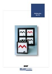
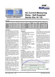
Hängebahnantriebe für den Leichtlastbereich Monorail conveyor drive for the light-duty sector<br />
Drehmoment ... 239 Nm Torque ... 239 Nm<br />
Leistung (50 Hz) ... 3 kW<br />
(60 Hz) ... 3,6 kW<br />
Abtriebsdrehzahl (50 Hz) 19 ... 172 /min<br />
(60 Hz) 23 ... 206 /min<br />
Power (50 Hz) ... 3 kW<br />
(60 Hz) ... 3,6 kW<br />
Output Speed (50 Hz) 19 ... 172 /min<br />
(60 Hz) 23 ... 206 /min<br />
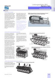
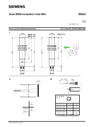
Hängebahnantriebe für den Schwerlastbereich Monorail conveyor drive for the heavy-duty sector<br />
Drehmoment ... 1019 Nm Torque ... 1019 Nm<br />
Leistung (50 Hz) ... 4 kW<br />
(60 Hz) ... 4,8 kW<br />
Abtriebsdrehzahl (50 Hz) 3,8 ... 270 /min<br />
(60 Hz) 4,6 ... 324 /min<br />
Lieferbedingungen Conditions of sale<br />
Es gelten ausschliesslich die Allgemeinen Lieferbedingungen<br />
für Erzeugnisse und Leistungen der Elektroindustrie (ZVEI)<br />
mit der Ergänzungsklausel zum erweiterten Eigentumsvorbehalt.<br />
Die jeweils aktuelle Fassung senden wir Ihnen auf Anfrage<br />
gerne zu.<br />
Eine Änderung der angegebenen Leistungen, Daten, Maße<br />
und Gewichte im Zuge der Weiterentwicklung bleibt vorbehalten.<br />
Bildliche Darstellung unverbindlich<br />
Maße in mm<br />
Gewichte in kg<br />
Beim Einbau der Getriebemotoren und Getriebe sind unsere<br />
Einbauhinweise der Betriebsanleitungen und die einschlägigen<br />
Vorschriften zu beachten.<br />
EHBN01 07.04 DE/EN 2 TÜ/TC 2697 / 324636<br />
Power (50 Hz) ... 4 kW<br />
(60 Hz) ... 4,8 kW<br />
Output Speed (50 Hz) 3,8 ... 270 /min<br />
(60 Hz) 4,6 ... 324 /min<br />
The deliveries are according to the general conditions for the<br />
supply of produckts and services of the electrical and electronics<br />
industy including the supplementary clause to the expanded<br />
reservation of ownership. We will send you the current<br />
version upon your enquiry.<br />
We reserve the right to change ratings, data, dimensions and<br />
weights without prior notice due to further development.<br />
Illustrations are not binding<br />
Dimensions are in mm<br />
Weights are in kg<br />
Gearmotors and gear units must be installed according to our<br />
installation instructions and applicable local and valid safety<br />
regulations.<br />
0 - 1
0 - 2<br />
<strong>MOTOX</strong> ® -N
<strong>MOTOX</strong> ® -N<br />
Inhalt Seite Contents Page<br />
Inhaltsverzeichnis 0 - 3 Table of Contents 0 - 3<br />
Technische Erläuterungen<br />
<strong>MOTOX</strong> ® -N Getriebe<br />
Allgemein 1 - 0<br />
Produkpalette 1 - 1<br />
Anstriche 1 - 2<br />
Auswahl des Antriebes 1 - 4<br />
Betriebsfaktor 1 - 5<br />
Formeln / SI-Einheiten 1 - 8<br />
EHB-System<br />
Allgemein 1 - 11<br />
<strong>MOTOX</strong> ® -N-EHB Getriebe 1 - 13<br />
<strong>MOTOX</strong> ® -N-EHB für den Leichtlastbereich 1 - 16<br />
<strong>MOTOX</strong> ® -N-EHB für den Schwerlastbereich 1 - 17<br />
MODULOG ® 1 - 18<br />
FLENDER-SIMATIC-EHB-Steuerung 1 - 20<br />
Checkliste 1 - 23<br />
Hängebahnantriebe 2 - 1<br />
Inhaltsverzeichnis 2 - 3<br />
Elektrischer Teil 3 - 1<br />
Inhaltsverzeichnis 3 - 3<br />
Adressen 4 - 1<br />
Deutschland 4 - 2<br />
Europa 4 - 3<br />
International 4 - 4<br />
Technical Information<br />
<strong>MOTOX</strong> ® -N Gear Units<br />
General 1 - 0<br />
Product Range 1 - 1<br />
Coats of paint 1 - 2<br />
Drive Selection 1 - 4<br />
Service Factor 1 - 5<br />
Formulas / SI-Units 1 - 8<br />
EHB-system<br />
General 1 - 11<br />
<strong>MOTOX</strong> ® -N-EHB Gear Units 1 - 13<br />
<strong>MOTOX</strong> ® -N-EHB Gear Unit Light Duty 1 - 16<br />
<strong>MOTOX</strong> ® -N-EHB Gear Unit Heavy Duty 1 - 17<br />
MODULOG ® 1 - 18<br />
FLENDER-SIMATIC-EHB-Steuerung 1 - 20<br />
Checkliste 1 - 23<br />
Monorail conveyor drive 2 - 1<br />
Table of Contents 2 - 3<br />
Electrical Section 3 - 1<br />
Table of Contents 3 - 3<br />
Addresses 4 - 1<br />
Germany 4 - 2<br />
Europe 4 - 3<br />
International 4 - 4<br />
0 - 3
1 - 0<br />
<strong>MOTOX</strong> ® -N<br />
Technische Erläuterungen <strong>MOTOX</strong> ® -N Getriebe Technical information <strong>MOTOX</strong> ® -N Gear Units<br />
Allgemein General<br />
Aufgabe der <strong>MOTOX</strong> ® -N Getriebemotoren und Getriebe ist die<br />
kostengünstige Reduktion der Motordrehzahl bzw. Steigerung<br />
des Motormoments von herkömmlichen Elektromotoren. Elektromagnetische<br />
Bremsen, Rücklaufsperren, Drehzahlwächter<br />
und zahlreiche weitere integrierte Optionen stehen zur Verfügung.<br />
An moderne Antriebssysteme werden heute hohe Anforderungen<br />
gestellt.<br />
Bei der Konzipierung des Getriebesystems <strong>MOTOX</strong> ® -N<br />
haben wir daher den Wünschen unserer Kunden nach mehr<br />
Betriebssicherheit und Wirtschaftlichkeit Rechnung<br />
getragen.<br />
Mit Hilfe modernster Berechnungsverfahren auf der Basis aktueller<br />
Forschungsergebnisse wurde die Verzahnungsgeometrie<br />
völlig neu gestaltet. Zusammen mit anderen<br />
konstruktiven und fertigungstechnischen Maßnahmen führte<br />
dies zu:<br />
Drehmomentsteigerungen, die abhängig von den Baugrößen<br />
und Drehzahlkonstellationen 80% erreichen können,<br />
einer guten Umweltverträglichkeit durch Minimierung des<br />
Geräuschpegels,<br />
hoher Anbau- und Einbauvariabilität durch ein geradliniges,<br />
modernes Gehäusedesign, das mittels 3D-CAD optimiert<br />
ist,<br />
der Einsparung von Kosten für Umkonstruktion beim<br />
Anwender durch Beibehaltung der bisherigen Anschlußabmessungen<br />
je Baugröße,<br />
Kostenvorteilen durch deutliche Erweiterung der<br />
Übersetzungsbereiche,<br />
einer Erhöhung der Betriebssicherheit durch Minimierung<br />
von Dichtflächen, Einsatz modernster Dichtungsmaterialien<br />
und neuartiger Dichtungssysteme an den Abtriebswellen.<br />
In Verbindung mit unseren Frequenzumrichtern<br />
projektieren und liefern wir Ihnen komplette, drehzahlvariable<br />
Antriebslösungen.<br />
The task of the <strong>MOTOX</strong> ® -N Gear Motors and Gear Units is<br />
the economic reduction of the motor output speed respectively<br />
the increase ot the motor torque of conventional electrical<br />
motors.<br />
Electromagnetic brakes, backstops, speed monitors and<br />
numerous integral options are available.<br />
High requirements are placed today on modern drive<br />
system.<br />
During the design of the gearbox system <strong>MOTOX</strong> ® -N we<br />
have taken into account the wishes of our customers for<br />
more service safety and economic efficiency.<br />
The gearing geometry has been totally redesigned with the<br />
help of the most modern calculation techniques and on the<br />
basis of actual research studies. This not only led to other<br />
constructive and productive technical measures, but also the<br />
following:<br />
torque increases up to 80% depending on the frame sizes<br />
and ratio constellations<br />
environmentally more tolerable due to reduction of the noise<br />
level,<br />
high extension and insertion variablity due to the straight ined,<br />
modern housing design which is optimised by means of<br />
3D-CAD,<br />
no costs for the customers for re-design due to the retention<br />
of the present connection measurements for each frame size,<br />
cost advantages due to the extensions of the ratio ranges,<br />
increased service safety due to minimising of the sealing faces,<br />
use of most modern sealing materials and a totally new<br />
output shaft sealing arrangement.<br />
We select and deliver complete variable speed drive<br />
solutions in connection with our frequency inverters.
<strong>MOTOX</strong> ® -N<br />
Produktpalette Product Range<br />
Getriebemotoren und Getriebe Gear Motors and Gear Units<br />
<strong>MOTOX</strong> ® -N / <strong>MOTOX</strong> ® -Stirnradgetriebemotoren<br />
und Stirnradgetriebe<br />
<strong>MOTOX</strong> ® -N / <strong>MOTOX</strong> ® -Kegelstirnradgetriebemotoren<br />
und Kegelstirnradgetriebe<br />
<strong>MOTOX</strong> ® -N / <strong>MOTOX</strong> ® -Flachgetriebemotoren<br />
und Flachgetriebe<br />
<strong>MOTOX</strong> ® -N / <strong>MOTOX</strong> ® -<br />
Stirnradschneckengetriebemotoren und<br />
Stirnradschneckengetriebe<br />
<strong>MOTOX</strong> ® -SC-Schneckengetriebemotoren<br />
und Schneckengetriebe<br />
<strong>MOTOX</strong> ® -N / <strong>MOTOX</strong> ® -Helical gear<br />
motors and gear units<br />
<strong>MOTOX</strong> ® -N / <strong>MOTOX</strong> ® -Bevel Helical gear<br />
motors and gear units<br />
<strong>MOTOX</strong> ® -N / <strong>MOTOX</strong> ® -Parallel Shaft gear<br />
motors and gear units<br />
<strong>MOTOX</strong> ® -N / <strong>MOTOX</strong> ® -Helical Worm gear<br />
motors and gear units<br />
<strong>MOTOX</strong> ® -SC-Worm gear motors and gear<br />
units<br />
Frequenzumrichter Frequency inverters<br />
Außerdem im Programm von Flender Tübingen: Besides in Flender Tübingen program:<br />
<strong>MOTOX</strong> ® -N und <strong>MOTOX</strong> ® Verstellgetriebemotoren<br />
<strong>MOTOX</strong> ® -Reibrad-Getriebemotoren und Reibradgetriebe<br />
<strong>MOTOX</strong> ® -Trommelmotoren<br />
Sondermotoren:<br />
<strong>MOTOX</strong> ® -Kreissägemotoren<br />
<strong>MOTOX</strong> ® -Frequenzgeneratoren<br />
<strong>MOTOX</strong> ® -N and <strong>MOTOX</strong> ® Variable speed gear motors<br />
<strong>MOTOX</strong> ® -Friction drive variators<br />
<strong>MOTOX</strong> ® -Conveyor drum motors<br />
Special Motors:<br />
<strong>MOTOX</strong> ® -Saw arbor motors<br />
<strong>MOTOX</strong> ® -Frequency converters<br />
1 - 1
Anstriche<br />
Zum Schutz der Antriebe gegen Korrosion und äußere<br />
Einflüße aller Art, bieten wir drei hochwertige Anstrichsysteme<br />
in zahlreichen Farbtönen an.<br />
Die Anstriche werden sorgfältig durch Spritzlackierung in modernsten<br />
Lackieranlagen appliziert.<br />
Weitere Farbtöne und Sonderanstriche sind auf Anfrage möglich.<br />
Übersicht<br />
Anstrichsystem<br />
Kunststoff<br />
(Standard)<br />
2K-PUR<br />
(Mehrpreis)<br />
2K-Epoxid<br />
(Mehrpreis)<br />
1 - 2<br />
Farbton typ.<br />
Einsatzbereich<br />
Standard: RAL 5015<br />
auf Wunsch:<br />
RAL 1007,1012,<br />
1023, 2000, 2004,<br />
3000, 5007, 5009,<br />
5010, 5012, 6011,<br />
7001, 7011, 7030,<br />
7032, 7035, 9005,<br />
9006, schwarz-matt<br />
weitere auf Anfrage<br />
Standard: RAL 7031<br />
auf Wunsch:<br />
RAL 1003,1018,<br />
2004, 5002, 5015,<br />
6011, 7000, 9010,<br />
9011, 9016,<br />
weitere auf Anfrage<br />
Standard: RAL 7035<br />
auf Wunsch:<br />
RAL 5015, 6018,<br />
7031, weitere auf<br />
Anfrage<br />
grundiert (RAL 7032)<br />
unlackiert -<br />
Standard-1-Schicht-<br />
Lackierung für den<br />
Innenbereich<br />
Standard-2-Schicht-<br />
Lackierung, insbesondere<br />
für die<br />
Aufstellung im Freien<br />
bzw. bei erhöhter<br />
Anforderung an den<br />
Korrosionsschutz<br />
hochwertige<br />
Lackierung im<br />
Außenbereich bzw.<br />
bei Beanspruchung<br />
durch Säure und<br />
Lauge (≤5%)<br />
zur Überlackierung:<br />
Haftvermittler für alle<br />
gängigen Lacksysteme,<br />
temporärer Korrosionsschutz<br />
zur Überlackierung:<br />
(Haftvermittler),<br />
temporärer<br />
Korrosionsschutz<br />
Überlackierbarkeit*<br />
mit Kunststofflack<br />
bzw. Kunstharzlack<br />
nach<br />
vorhergehendem<br />
Anschleifen mit:<br />
2K-PUR-Lack<br />
2K-Epoxid-Lack<br />
nach<br />
vorhergehendem<br />
Anschleifen mit:<br />
2K-PUR-Lack<br />
2K-Epoxid-Lack<br />
2K-AC-Lack<br />
sehr gut mit: Kunststofflack,Kunstharzlack,<br />
2K-PUR-<br />
Lack, 2K-Epoxid-<br />
Lack, SH-Lack,<br />
2K-AC-Lack<br />
sehr gut mit<br />
Kunststofflack,<br />
Kunstharzlack, Ölfarbe,<br />
Bitumenfarbe<br />
2K-PUR-Anstrich,<br />
2K-Epoxid-Anstrich<br />
* Hinweis:<br />
Die Angaben zur Überlackierbarkeit stellen keine Freigabe im<br />
Sinne einer Garantie für die Qualität des von Ihrem Lieferanten<br />
angelieferten Lackes dar.<br />
Für die Qualität und Verträglichkeit haftet allein der Lackhersteller.<br />
chem. phys.<br />
Beständigkeit<br />
gute Beständigkeit gegen<br />
Reinigungsmittel, Öl und<br />
Benzin, beständig gegen<br />
kurzzeitige<br />
Beanspruchung durch verdünnte<br />
Säure und Lauge<br />
(≤3%), nicht<br />
lösungsmittelbeständig;<br />
nicht<br />
wasserdampfbeständig<br />
sehr gute Beständigkeit<br />
gegen Öl, Fett, Benzin,<br />
Wasser, Seewasser und<br />
Reinigungsmittel; gute<br />
Beständigkeit gegen<br />
Witterungseinflüsse und<br />
verdünnte Säure und<br />
Lauge (≤3%); gute<br />
mechanische Beständigkeit<br />
gegen Abrasion<br />
ausgezeichnete<br />
Beständigkeit gegen<br />
schwache Säure und Lauge<br />
(≤5%), Öl, Fett, Benzin,<br />
Kühlemulsion, Salz, Lösungsmittel;<br />
zähharter und<br />
kratzfester Lackfilm<br />
gute Beständigkeit gegen<br />
Reinigungsmittel, gute<br />
Salzsprühbeständigkeit<br />
und beständig gegen Öl<br />
und Benzin<br />
-<br />
<strong>MOTOX</strong> ® -N<br />
Temperaturbeständigkeit<br />
-40°C bis 100°C<br />
kurzzeitig bis<br />
140°C<br />
-40°C bis 150°C<br />
-40°C bis 150°C<br />
-40°C bis 150°C<br />
(-40°C bis<br />
150°C)<br />
Bemerkungen<br />
Standardlackierung<br />
mit sehr guter Haftungseigenschaft;<br />
nicht geeignet für<br />
Lagerung im Freien,<br />
Aufstellung im<br />
Freien<br />
Standardlackierung<br />
für Kühlturm- und<br />
Rührwerksantriebe<br />
bzw. bei<br />
Anforderung Seewasserbeständigkeit<br />
unter Deck o. ä.<br />
2K-Epoxid-Lack<br />
“kreidet” bei Auf-<br />
stellung im Freien<br />
aus (ohne Einfluß<br />
auf Qualität), hoher<br />
Glanz mit guter mechanischerWiderstandsfähigkeit<br />
Haftvermittler mit<br />
sehr guter<br />
Haftungseigenschaft<br />
und gutem<br />
Korrosionsschutz<br />
GG-Teile<br />
tauchgrundiert,<br />
St-Teile grundiert<br />
oder verzinkt<br />
Al- und<br />
Kunststoffteile<br />
unbehandelt
<strong>MOTOX</strong> ® -N<br />
Overview:<br />
Paint system Color tone<br />
Standard: RAL 5015<br />
Typical area<br />
of use<br />
Plastic<br />
(Standard)<br />
2K-PUR<br />
(extra charge)<br />
2K-Epoxy<br />
(extra charge)<br />
on demand:<br />
RAL 1007, 1012,<br />
1023, 2000, 2004,<br />
3000, 5007, 5009,<br />
5010, 5012, 6011,<br />
7001, 7011, 7030,<br />
7032, 7035, 9005,<br />
9006, black-dull,<br />
others on request<br />
Standard: RAL 7031<br />
on demand:<br />
RAL1003, 1018,<br />
2004, 5002, 5015,<br />
6011, 7000, 9010,<br />
9011, 9016,<br />
others on request<br />
Standard: RAL 7035<br />
on demand:<br />
RAL 5015, 6018,<br />
7031,<br />
others on request<br />
Primed (RAL 7032)<br />
Unpainted -<br />
Standard 1-layer<br />
coat of lacquer for<br />
the internal area<br />
Standard 2-layer<br />
coat of lacquer<br />
especially for<br />
installation in the<br />
open or in case of<br />
increased<br />
demands on<br />
corrosion<br />
protection<br />
High-quality coat of<br />
lacquer for the<br />
external area or in<br />
case of attack by<br />
diluted acid and<br />
alkaline solution<br />
(≤5%)<br />
For overpainting:<br />
adhesive agent for<br />
all common paint<br />
systems,<br />
temporary corrosion<br />
protection<br />
For overpainting:<br />
(adhesive agent)<br />
temporary<br />
corrosion<br />
protection<br />
Coats of paint<br />
For protection of the drives against corrosion and all kinds of<br />
ambient influences, we offer three high quality painting<br />
systems in several color tones.<br />
All coats of paint are applied carefully by spray painting in the<br />
most modern painting plants.<br />
Other color tones and special paintings are possible on request.<br />
Overpaintability * Chem. phys.<br />
resistance<br />
With plastic lacquer or<br />
synthetic resin<br />
lacquer<br />
After preceeding<br />
grinding with:<br />
2K-PUR lacquer<br />
2K-Epoxy lacquer<br />
After preceeding<br />
grinding with:<br />
2K-PUR lacquer<br />
2K-Epoxy lacquer<br />
2K-AC lacquer<br />
Excellent with:<br />
plastic lacquer, synthetic<br />
resin lacquer,<br />
2K-PUR lacquer,<br />
2K-Epoxy lacquer, SH<br />
lacquer, 2K-AC lacquer<br />
Excellent with:<br />
plastic lacquer,<br />
synthetic resin lacquer,<br />
oil paint, bitumenous<br />
paint, 2K-PUR paint<br />
2K-Epoxy paint<br />
Good resistance to<br />
cleaning agents, oil<br />
and benzine,<br />
resistant to short-<br />
time attack by diluted<br />
acid and alkaline solution<br />
(≤3%), not<br />
resistant to solvent<br />
not resitant to watervaour<br />
Excellent<br />
resistance to<br />
weak acid and<br />
alkaline<br />
solution (≤3%),<br />
oil, grease, benzine,<br />
cooling emulsion,<br />
salt, solvent; tough<br />
and scratch-resistant-coating<br />
film<br />
Excellent resistance<br />
to weak acid and alkaline<br />
solution (≤5%),<br />
oil, grease, benzine,<br />
cooling emulsion,<br />
salt, solvent; tough<br />
and scratch-resistant-coating<br />
film<br />
Good resistance to<br />
cleaning agent, to<br />
salt spraying and<br />
resistant to oil and<br />
benzine<br />
Temperature<br />
resistance<br />
-40°C to 100°C<br />
up to 140°C for<br />
a short time<br />
-40°C to 150°C<br />
-40°C to 150°C<br />
-40°C to 150°C<br />
- (-40°C to 150°C)<br />
Remarks<br />
Standard coat of<br />
lacquer with<br />
excellent adhesive<br />
characteristics,<br />
not suitable for<br />
storage in the open;<br />
not suitable for<br />
installation in the<br />
open air<br />
Standard coat of<br />
lacquer for cooling<br />
tower and agitator<br />
drive or if sea<br />
water resistance<br />
below deck or<br />
similar is required<br />
2K-Epoxy lacquer<br />
“chalks” in case of<br />
installation in the<br />
open (does not<br />
effect the quality),<br />
high gloss with<br />
good mechanical<br />
resistance<br />
Adhesive agent<br />
with excellent<br />
adhesive<br />
characteristics and<br />
good corrosion<br />
protection<br />
Components from<br />
grey cast iron dip-primed,<br />
components<br />
from steel primed or<br />
galvanised, components<br />
from Al and plastic<br />
untreated<br />
* Note:<br />
The information for varnishing (over-coating) do not represent<br />
a release in the sense of a warranty for the quality of the coating<br />
material delivered by your supply.<br />
For the quality and compatibility only to the varnish manufactures<br />
is responsible.<br />
1 - 3
Auswahl des Antriebs Drive selection<br />
Für die Festlegung des Antriebes sind die Einsatzbedingungen<br />
maßgebend. Sie werden durch den Betriebsfaktor f B<br />
erfaßt.<br />
Bei Normalbetrieb, d.h. bei gleichmäßiger Belastung durch die<br />
Arbeitsmaschine, kleinen zu beschleunigenden Massen und<br />
geringer Schalthäufigkeit, ist f B = 1. Für davon abweichende<br />
Einsatzbedingungen läßt sich dieser Betriebsfaktor aus den Tabellen<br />
(siehe “Betriebsfaktor”) entnehmen. Dieser Faktor bestimmt<br />
die Getriebegröße, nicht aber die Leistung des<br />
Antriebsmotors. Bei bekannter Motorleistung und Getriebeabtriebsdrehzahl<br />
wird dann aus der Typenliste ein Getriebetyp gewählt,<br />
dessen (zulässiger) Betriebsfaktor f B ≥ f Bges ist.<br />
Sofern es sich um Antriebe mit besonderen Einsatzbedingungen<br />
handelt, wie häufiges Reversieren, Kurzzeit- und Aussetzbetrieb,<br />
abnorme Temperaturverhältnisse, Gegenstrombremsung,<br />
extreme Querkräfte auf die Getriebeabtriebswelle<br />
usw., stehen wir Ihnen gerne für die Auslegung des Antriebs<br />
zur Verfügung.<br />
1 - 4<br />
<strong>MOTOX</strong> ® -N<br />
Operating conditions decide the selection of drive. These conditions<br />
are taken into account with service factor f B.<br />
For normal operating conditions with uniform loadings, low<br />
masses to be accelerated and few starts, this service factor<br />
f B = 1. For different operating conditions see table “Service<br />
factor”. This factor decides the speed reducer size, not, however,<br />
the drive motor rating. With known motor rating and output<br />
speed enter the type list and choose a speed reducer type,<br />
whose permissible service factor f B ≥ f Bges.<br />
We shall be pleased to advise on drives for special operating<br />
conditions, e.g. reversing, short time or intermittent operation,<br />
abnormal temperature, counter-current braking, extreme<br />
overhung loads on output shaft etc..<br />
Dazu werden folgende Daten benötigt: For that purpose we require the following data:<br />
1. Art der getriebenen Maschine<br />
2. Tägliche Betriebszeit<br />
3. Erforderliche Antriebsleistung [kW] oder<br />
Drehmoment [Nm]<br />
4. Nenndrehzahl des Getriebes [min -1 ] bzw. Übersetzung i<br />
5. Betriebsspannung [V] und Frequenz [Hz]<br />
6. Art der Einschaltung (direkt oder Stern-Dreieck)<br />
7. Betriebsart, Schalthäufigkeit, Umrichterbetrieb<br />
8. Massenträgheitsmoment Jext [kg m 2 ] der getriebenen<br />
Maschine bezogen auf die Nenndrehzahl des Getriebes<br />
9. Art des Abtriebes bzw. Eintriebes (direkt, Kupplung,<br />
Riemen, Ketten, Zahnräder)<br />
10. Querkraft FR [N] an den Wellen und Kraftrichtung mit<br />
Abstand des Angriffpunktes vom Wellenbund, Axialkraft<br />
FA [N]<br />
11. Umgebungstemperatur [°C]<br />
12. Bauform<br />
13. Gewünschtes Bremsmoment [Nm]<br />
Müssen die Motoren ausländischen Vorschriften entsprechen,<br />
bitten wir diese Vorschriften genau zu bezeichnen.<br />
1. Type of driven machine<br />
2. Daily operating period<br />
3. Required power [kW] or torque [Nm]<br />
4. Nom. speed of gear unit [r.p.m.] or ratio i<br />
5. Voltage [V] and frequency [Hz]<br />
6. Starting (direct on line or star/delta)<br />
7. Type of operation, starting cycles frequency, frequency<br />
inverter operation<br />
8. Moments of inertia Jext [kg m 2 ] of driven machine referred<br />
to nom. output speed of gear unit<br />
9. Connection to input or output shaft (direct, coupling, belt<br />
drive, chain drive, gears)<br />
10. Overhung loads FR [N] on shafts and their direction with<br />
distance of load application point from shaft shoulder,<br />
thrust forces FA [N]<br />
11. Ambient temperature [°C<br />
12. Mounting position<br />
13. Desired braking torque [Nm]<br />
In case motors have to conform to foreign standards, these<br />
standards should be specified exactly.
<strong>MOTOX</strong> ® -N<br />
Betriebsfaktor Service Factor<br />
f Bges ≤ f B<br />
f Bges = Betriebsfaktor der Arbeitsmaschine f Bges = Service Factor of driven machine<br />
f B<br />
= zulässiger Betriebsfaktor des Getriebes,<br />
siehe Leistungsdaten<br />
Bei Stirnrad-, Kegelrad- und Flachgetrieben sind die<br />
Betriebsfaktoren<br />
f B2 (für Kurzzeitbetrieb) = 1<br />
und<br />
f B3 (für Umgebungstemperatur 20°) = 1<br />
d.h.<br />
Betriebsfaktor f B1<br />
Laufzeit pro Tag<br />
Daily operation<br />
Schaltungen / h<br />
Starts / h<br />
Stoßgrad<br />
Load classification<br />
Arbeitsmaschine<br />
Driven machine<br />
4 Stunden<br />
4 hours<br />
f Bges = f B1 • f B2 • f B3<br />
f B<br />
f Bges = f B1 ≤ f B<br />
= Permissible service factor of speed reducer,<br />
see Performance Data<br />
At Helical, Bevel Helical and Parallel Shaft Gears the Service<br />
Factor<br />
f B2 (for short term operation) = 1<br />
and<br />
f B3 (for ambient temperature 20°) = 1<br />
i.e.<br />
8 Stunden<br />
8 hours<br />
Service Factor f B1<br />
16 Stunden<br />
16 hours<br />
24 Stunden<br />
24 hours<br />
200 200 200 200<br />
I 0,8 0,9 1 0,9 1 1,1 1 1,1 1,2 1,2 1,3 1,5<br />
II 1 1,1 1,3 1,1 1,2 1,3 1,2 1,4 1,5 1,4 1,5 1,6<br />
III 1,3 1,4 1,5 1,4 1,5 1,6 1,5 1,6 1,7 1,6 1,7 1,8<br />
1 - 5
Betriebsfaktor Service Factor<br />
Bei Laufzeiten bis 4 Stunden pro Tag sowie bei Verwendung<br />
elastischer Kupplungen oder Riementrieben können kleinere<br />
f B-Faktoren gewählt werden. Bei besonders schweren Antriebsfällen<br />
wie Reversierbetrieb bitten wir um Rückfrage.<br />
1 - 6<br />
<strong>MOTOX</strong> ® -N<br />
For daily operating periods up to 4 hours and if flexible coupling<br />
or belt drives are being used, lower f B factors can be chosen.<br />
Very heavy shock load applications such as reversing<br />
operation, please refer to office.<br />
Stoßgrad Arbeitsmaschine Load Classification Driven Machine<br />
I<br />
fast stoßfrei<br />
II<br />
mäßige Stöße<br />
III<br />
heftige Stöße<br />
Massenbeschleunigungs-<br />
=<br />
faktor<br />
Massenbeschleunigungsfaktor ≤ 0,3:<br />
Stromerzeuger, Gurtförderer, Plattenförderer,<br />
Förderschnecken, Leichtaufzüge,<br />
Elektrozüge, Vorschubantriebe von Werkzeugmaschinen,<br />
Turbogebläse, Kreiselverdichter,<br />
Rührer und Mischer für<br />
gleichmäßige Dichte.<br />
Massenbeschleunigungsfaktor ≤ 3:<br />
Hauptantrieb von Werkzeugmaschinen,<br />
schwere Aufzüge, Drehwerke, Kräne,<br />
Grubenlüfter, Rührer und Mischer für<br />
unregelmäßige Dichte, Kolbenpumpen mit<br />
mehreren Zylindern, Zuteilpumpen.<br />
Massenbeschleunigungsfaktor ≤ 10:<br />
Stanzen, Scheren, Gummikneten, Walzwerks-<br />
und Hüttenmaschinen, Löffelbager,<br />
schwere Zentrifugen, schwere Zuteilpumpen,<br />
Rotary- Bohranlagen, Brikettpressen,<br />
Kollergänge.<br />
alle äußeren<br />
Massenträgheitsmomente<br />
Massenträgheitsmoment des<br />
Antriebsmotors<br />
I<br />
light shocks<br />
II<br />
moderate shocks<br />
III<br />
heavy shocks<br />
1 umgerechnet auf Motordrehzahl 1<br />
Recalculated to motor speed<br />
1<br />
Mass<br />
acceleration =<br />
faktor<br />
Mass acceleration factor ≤ 0,3:<br />
Generators, belt conveyors, platform<br />
conveyors, screw conveyors, light<br />
hoists, electric hoists, auxiliary<br />
machine tool drives, turbo blowers,<br />
turbo compressors, agitators and<br />
mixers for light uniform density<br />
materials.<br />
Mass acceleration factor ≤ 3:<br />
Main machine tool drives, hoists,<br />
slewing gear, cranes, induced draught<br />
fans, mixer and agitator for materials<br />
with variable density, multicylinder<br />
piston pumps, metering pumps.<br />
Mass acceleration factor ≤ 10:<br />
Punch presses, shears, Banbury<br />
mixers, rolling mill and foundry drivers,<br />
bucket dredger, heavy centrifugal<br />
drives, heavy metering pumps, rotary<br />
drilling equipment, briquet presses,<br />
pug mills.<br />
all exterior<br />
moments of inertia<br />
moments of inertia<br />
drive motors<br />
1
<strong>MOTOX</strong> ® -N<br />
Betriebsfaktor f B2 für Kurzzeitbetrieb Service factor f B2 for short time operation<br />
Betriebsfaktor f B3 für Umgebungstemperatur Service factor f B3 for ambient temperature<br />
f B3 < 1 für Temperaturen unter 20°C nur nach Rücksprache<br />
verwendbar!<br />
q Um<br />
f B2<br />
1,0<br />
0,9<br />
0,8<br />
0,7<br />
0,6<br />
0,5<br />
f B3<br />
2,0<br />
1,9<br />
1,8<br />
1,7<br />
1,6<br />
1,5<br />
1,4<br />
1,3<br />
1,2<br />
1,1<br />
1,0<br />
0,9<br />
Umgebungstemperatur<br />
0 10 20 30 40 50 60 70 80 90 100<br />
0,8<br />
0 10 20 30 40 50 60 qUm [°C]<br />
f B3 < 1 for temperatures below 20°C can only be used after<br />
refering to factory!<br />
q Um<br />
ED<br />
[%]<br />
Ambient temperature<br />
1 - 7
Wichtige Gleichungen der Antriebstechnik Engineering formulas<br />
Internationales System (SI)<br />
International System (SI)<br />
Arbeit / Work:<br />
W = F ⋅ s<br />
W = P ⋅ t<br />
W = T ⋅ Φ<br />
W<br />
W<br />
1<br />
--Jω<br />
2<br />
2<br />
=<br />
---------------<br />
1<br />
J n<br />
182, 5<br />
2<br />
= ⋅ ⋅<br />
Leistung / Power:<br />
Hub / Lifting motion:<br />
1 - 8<br />
Technisches Maßsystem (TM)<br />
Technical Measuring System (TM)<br />
Rotation / Rotary motion:<br />
1<br />
P = T ⋅ ω<br />
N = --------------- ⋅T ⋅ n<br />
0, 974<br />
1<br />
P = ------------ ⋅T ⋅ n<br />
9, 55<br />
Translation / Linear motion:<br />
Bremszeit / Braking time:<br />
1 J n<br />
t ------------<br />
9, 55<br />
⋅<br />
= ⋅ ----------<br />
T<br />
Massenträgheitsmoment / Mass moment of inertia:<br />
m = geradlinig bewegte Masse in kg<br />
v = Geschwindigkeit der Masse in m/s<br />
nmot = Motordrehzahl in min -1 .<br />
Schalthäufigkeit / Stop-start frequency:<br />
m = linear moved mass in kg<br />
v = velocity of the mass in m/s<br />
n mot = motor speed in min -1<br />
<strong>MOTOX</strong> ® -N<br />
Zo = Leerschalthäufigkeit in1/h<br />
Zs = zulässige Schalthäufigkeit in 1/h<br />
TL TH Jmot = Lastmoment in Nm<br />
= mittl. Hochlaufmoment des Motors in Nm<br />
= Massenträgheitsmoment des Motors in kgm 2<br />
Jzus = Massenträgheitsmoment der Last in kgm 2<br />
Zo = no-load stop-start frequence/hour<br />
Zs = permissible stop-start frequence/hour<br />
TL TH Jmot = torque load in Nm<br />
= mean running-up torque of the motor in Nm<br />
= Moment of inertia of the motor in kgm 2<br />
Jzus = Moment of inertia of the load in kgm 2<br />
1 – T ⁄ T<br />
L Hm<br />
Z = Z ⋅ ---------------------------------------s<br />
o 1 + J ⁄ J<br />
zus mot<br />
Z =<br />
s<br />
1 – T ⁄ T<br />
L Hm<br />
Z ⋅ ---------------------------------------o<br />
1 + J ⁄ J<br />
zus mot<br />
Drehstrommotor / Three phase motor:<br />
Leistungsaufnahme / Power input: Leistungsabgabe / Power output:<br />
Übertemperatur der Wicklung / Temperature increase of motor windings<br />
∆T<br />
=<br />
R – R<br />
w k<br />
--------------------- ⋅ ( 235 + υ )<br />
R k<br />
k<br />
∆T Übertemperatur in Kelvin<br />
υk Umgebungstemperatur (k = kalt) in °C<br />
Rw ; Rk Wicklungswiderstand (w = warm; k = kalt) in Ω<br />
A = P ⋅ s<br />
1<br />
E ------------ GD<br />
7160<br />
2 n 2<br />
= ⋅ ⋅<br />
Drehmoment / Torque:<br />
T = F ⋅ r<br />
M = P ⋅ r<br />
T =<br />
P<br />
9, 55⋅---<br />
n<br />
M =<br />
N<br />
0, 974 ⋅ --n<br />
P<br />
W<br />
= ----<br />
N<br />
t<br />
P = G ⋅ v<br />
N<br />
P = F ⋅ v<br />
N<br />
A<br />
= ---<br />
T<br />
1<br />
= --------------- ⋅G ⋅ v<br />
0, 102<br />
1<br />
= --------------- ⋅P ⋅ v<br />
0, 102<br />
1<br />
N ---------<br />
375<br />
GD 2 ⋅ n<br />
= ⋅ -------------------<br />
Tb<br />
2<br />
m⋅r J ------------- ------<br />
G<br />
r<br />
2 2g<br />
2<br />
GD<br />
= = ⋅<br />
J<br />
2<br />
= -----------<br />
4<br />
v 2<br />
J = 91, 2 ⋅m⋅ -------------<br />
GD<br />
red<br />
n<br />
mot<br />
P = 3 ⋅U⋅ I ⋅ cosϕ<br />
P =<br />
1<br />
2<br />
∆T<br />
2 G<br />
--- d<br />
2<br />
2<br />
= ⋅<br />
3 ⋅ U⋅ I ⋅ cosϕ<br />
η<br />
R – R<br />
w k<br />
=<br />
--------------------- ⋅ ( 235 + υ )<br />
R k<br />
k<br />
⋅<br />
∆T Temperature increase at Kelvin<br />
υk Ambient temperature (k: cold) in °C<br />
Rw ; Rk Resistance of motor winding (w: warm; k: cold) in Ω
<strong>MOTOX</strong> ® -N<br />
SI-Einheiten SI-Units<br />
Größe Description Formelzeichen/Symbol Einheitszeichen/Unit symbol<br />
SI bisher<br />
previous<br />
SI bisher<br />
previous<br />
Beziehung oder<br />
Umrechnungsfaktor *<br />
Relation or conversion<br />
factor *<br />
Länge (Weg) Length (length of path) L(s) L, s m m 1 km = 1000 m<br />
Fläche Area A F m2 m2 1 m 2 = 100 dm2 Volumen Volume V V m 3<br />
m 3<br />
1 m 3 = 1000 dm 3<br />
1 dm 3 = 1 l<br />
ebener Winkel Angle in one plane α, β, γ α, β, γ rad Grad °<br />
Drehwinkel Angle of rotation φ ϕ degree<br />
1 rad = 1 m/m<br />
1 L = π/2 rad<br />
1° =π/180 rad<br />
1’ = 1°/60<br />
1’’ = 1’/60<br />
Zeit Time<br />
1 min = 60 s<br />
1 h = 60 min<br />
Zeitspanne Time interval t t s s 1 d = 24 h<br />
Dauer Duration 1 a = 24 h<br />
Frequenz Frequency f f Hz 1/s 1 Hz = 1/s<br />
Drehzahl Rotational speed n n min -1 U/min<br />
r.p.m<br />
Geschwindigkeit Linear speed v v m/s m/s<br />
Beschleunigung<br />
Fallbeschleunigung<br />
Acceleration<br />
Gravitational Acceleration<br />
a<br />
g<br />
b<br />
g<br />
m/s 2<br />
m/s 2<br />
Umdrehung je min<br />
revelutions per min.<br />
1<br />
1 km/h =<br />
3,6<br />
m/s<br />
g = 9,81 m/s 2<br />
Winkelgeschwindigkeit Angular velocity ω Ω rad/s 1/s<br />
Winkelbeschleunigung Angular acceleration α ξ rad/s 2<br />
1/s 2<br />
Masse Mass m m kg kg 1<br />
Dichte Density d kg/dm 3<br />
kg/dm 3<br />
10 3<br />
Kraft<br />
Gewichtskraft<br />
Force<br />
Weight<br />
F<br />
G<br />
P, K<br />
G<br />
N kp 9,81 1 N = 1 kg · 1 m/s 2<br />
Druck<br />
Pressure<br />
p p<br />
Pa<br />
N/m<br />
mech. Spannung<br />
Mechanical stress σ σ<br />
2<br />
N/mm 2<br />
kp/cm 2<br />
kp/mm 2<br />
1 Pa = 1 N/m 2<br />
9,81 · 10 4<br />
9,81<br />
Arbeit<br />
Work<br />
W A<br />
kpm<br />
9,81<br />
Energie<br />
Energy<br />
W E<br />
J<br />
kcal<br />
4187<br />
Wärmemenge<br />
Amount of heat<br />
Q Q<br />
1 J = 1 Nm = 1 Ws<br />
Moment einer Kraft<br />
Moment of a fore<br />
Mt 9,81<br />
Drehmoment<br />
Torque<br />
T Md Nm kpm<br />
1 Nm = 1 J<br />
Biegemoment<br />
Bending moment<br />
Mb Leistung Output power P N W PS<br />
735,5<br />
1 W = 1 J/s = 1 Nm/s<br />
Massenträgheitsmoment Moment of inertia J θ kgm 2<br />
kpm 2<br />
9,81<br />
dynamische Viskosität Dynamical viscosity η η Pa · s P 10 -1<br />
kinematische Viskosität Kinematical viscosity υ υ m 2 /s St 10 -4<br />
elektr. Stromstärke Electrical current Ι Ι A A 1 A = 1 W/V = 1 V/Ω<br />
elektr. Spannung Voltage U U V V 1 V = 1 W/A<br />
elektr. Widerstand Electrical resistance R R Ω Ω 1 Ω = 1 V/A = 1/S<br />
elektr. Leitwert Conductance G G S S 1 S = 1/Ω<br />
elektr. Kapazität Capacitance C C F F 1 F = 1 C/V<br />
Elektrizitätsmenge<br />
Ladung<br />
Quantity of electricity<br />
Charge<br />
Q Q C C 1 C = 1 A · s<br />
Induktivität Self inductance L L H H 1 H = 1 Vs/A<br />
magnet. Flußdichte<br />
Induktion<br />
Magnetic flux density<br />
Magnetic induction<br />
B B T G<br />
10 4<br />
1 T = 1 Wb/m 2<br />
magnet. Feldstärke Magnetic field strength H H A/m A/m<br />
magnet. Fluß Magnetical flux φ φ Wb M<br />
10 8<br />
1 Wb = 1 V · s<br />
Temperatur Temperature T(ϑ) t K(°C) °C 0 K = -273,15 °C<br />
* Zahlenwert einer Größe nach bisher üblichen Einheiten multipliziert<br />
mit dem Umrechnungsfaktor ergibt den Zahlenwert der Größe nach<br />
SI-Einheiten.<br />
* The value in SI-units can be obtained by applying the conversion<br />
factor shown.<br />
1 - 9
1 - 10<br />
<strong>MOTOX</strong> ® -N
<strong>MOTOX</strong> ® -N<br />
Technische Erläuterung EHB-System Technical information monorail drive systems<br />
Allgemein General<br />
Elektro-Hängebahn-Systeme (sog. EHB-Systeme) stellen für<br />
den innerbetrieblichen Materialfluss ein modernes und wirtschaftliches<br />
Transportsystem dar.<br />
Sowohl der Transport kleiner Lasten, beispielsweise in der<br />
Vor- und Endmontage von Haushaltsgeräten, als auch der<br />
Transport von schweren Lasten wie komplette Fahrzeuge in<br />
der Automobilindustrie stellen typische Einsatzgebiete dar.<br />
EHB-Systeme haben sich in vielen Industriebereichen fest<br />
etabliert:<br />
Automobilindustrie Automotive industry<br />
Monorail conveyor drive systems are a modern, economical<br />
means of transport for the in-company materials flow<br />
Haushaltsgeräteindustrie Domestic appliance industry<br />
Both the transport of small loads, for example, in the pre- and<br />
final assembly of domestic appliances, and the transport of<br />
heavy loads such as complete vehicles in the automotive industry<br />
are typical areas of application. Monorail drive systems<br />
have established themselves in many sectors of industry.<br />
Lager- und Verteilzentren Storage and distribution centres<br />
Personentransport Passenger transport<br />
Chemische und Pharmazeutische Industrie Chemical and pharmaceutical industry<br />
Lebensmitteltechnik mit ganz besonderen hygienischen<br />
Anforderungen<br />
Food technology with very special hygiene requirements<br />
Freizeitparks mit "Sicherheit" als wichtigstes Kriterium Leisure parks where "security" is the most important criterium<br />
EHB-Systeme erobern die dritte Dimension, d.h. der Deckenraum<br />
wird ausgenutzt. Ganz nebenbei bleibt somit der Bodenbereich<br />
frei, sodass Gefahren durch den Materialtransport<br />
weitgehend vermieden werden. EHB-Systeme bieten zudem<br />
weitergehende Vorteile:<br />
Flexible Streckenführung und Anpassung an jede Linienführung<br />
Monorail drive systems utilise the third dimension, i.e. they utilise<br />
the ceiling area. As a consequence the floor area is left<br />
free, thus largely avoiding hazards from materials transport.<br />
Monorail drive systems offer further advantages:<br />
Flexible track routing and adaptation to any line layout<br />
1 - 11
Hohe und flexible Transportgeschwindigkeit, auch bei hohen<br />
Gewichten<br />
Hohe Verfügbarkeit: jedes Fahrzeug hat seinen eigenen und<br />
unabhängigen Antrieb. Bei einer Störung kann es einfach<br />
entfernt werden ohne die Gesamtanlage zu beeinflussen<br />
1 - 12<br />
<strong>MOTOX</strong> ® -N<br />
High, flexible transport speed, even with heavy weights<br />
High availability: each vehicle has its own, independent drive.<br />
In the event of a fault it can be easily removed without affecting<br />
the system as a whole<br />
Niedrige Wartungskosten aufgrund geringen Verschleisses Low maintenance costs due to low wear<br />
Unproblematische Erweiterung durch zusätzliche Fahrwagen<br />
EHB-Antriebe verlangen nach speziellen Lösungen. Basierend<br />
auf dem Getriebemotorenprogramm <strong>MOTOX</strong> ® -N bietet<br />
die FLENDER TÜBINGEN GMBH daher ein eigenständiges<br />
Programm an EHB-Getriebemotoren. Der wesentliche Unterschied<br />
und zugleich Besonderheit der <strong>MOTOX</strong> ® -N-EHB Getriebe<br />
ist die mechanische Ausrückkupplung zur Trennung<br />
des Kraftflusses zwischen Antrieb und Fördersystem.<br />
Der Einsatz der mechanischen Ausrückkupplung kann dabei<br />
folgende Gründe haben:<br />
Zur Inbetriebnahme der Anlage in der Entstehungsphase,<br />
noch bevor elektrische Leistung zur Verfügung steht. Hier<br />
können die Fahrwagen von Hand im ausgekuppelten Zustand<br />
auf die Förderschienen bewegt werden.<br />
Im Störfall zur Weiter- bzw. Umleitung des Fahrwagens von<br />
Hand, um ein Auffahren des folgenden Fahrwagens zu verhindern.<br />
Bei starker Steigung oder im starken Gefälle zur Weiterleitung<br />
des Fahrwagens mit Hilfe eines Kettenförderers.<br />
Problemfree extension by means of additional trolleys<br />
Monorail drive systems call for special solutions. On the basis<br />
of the <strong>MOTOX</strong> ® -N gear motor programme, FLENDER<br />
TÜBINGEN GMBH therefore offers an independent monorail<br />
drive gear motor programme. The essential difference and at<br />
the same time special feature of <strong>MOTOX</strong> ® -N monorail drive<br />
gear units is the mechanical disengagement clutch to interrupt<br />
the power flow between the drive and the conveyor system.<br />
The mechanical disengagement clutch may be used for the<br />
following reasons:<br />
For starting up the system in the initial phase before electric<br />
power is available. Here the trolleys can be moved in disengaged<br />
condition onto the conveyor rails manually.<br />
In the event of faults, for manual onward-movement and diversion<br />
of the trolley to prevent collision with the following<br />
trolley.<br />
On steep slopes, to move the trolley on with the aid of a<br />
chain conveyor.
<strong>MOTOX</strong> ® -N<br />
<strong>MOTOX</strong> ® -N-EHB Getriebe <strong>MOTOX</strong> ® -N-Monorail Drive Gear Units<br />
<strong>MOTOX</strong> ® -N-EHB-Getriebe sind Teil des <strong>MOTOX</strong> ® -N-Baukastensystems.<br />
Ein fein abgestuftes Getriebeprogramm mit 6 Getriebegrößen<br />
ermöglicht stets die Auswahl des geeigneten Antriebs und<br />
bietet somit Kostenvorteile.<br />
Neben Getrieben, die der VDI-Richtlinie 3643 entsprechen,<br />
deckt das Programm auch den Schwerlast-EHB-Bereich ab.<br />
Wahlweise stehen <strong>MOTOX</strong> ® -N-EHB-Kegelstirnradgetriebe<br />
oder <strong>MOTOX</strong> ® -N-EHB-Stirnradschneckengetriebe zur Auswahl.<br />
Die formschönen Gehäuse aus Grauguß entsprechen dem<br />
<strong>MOTOX</strong> ® -N-Standard-Programm. Die Gehäuse sind stabil<br />
und schwingungsdämpfend. Auch die Verzahnung ist dem flexiblen<br />
Baukastensystem des <strong>MOTOX</strong> ® -N-Standard-Programms<br />
entnommen und bietet mit einer Vielzahl fein<br />
abgestufter Übersetzungen einen breiten Geschwindigkeitsbereich.<br />
Eine hohe Verfügbarkeit aufgrund des Baukastensystems ist<br />
gewährleistet.<br />
Hohe Drehmomente sowie hohe zulässige Radlasten zeichnen<br />
das neue <strong>MOTOX</strong> ® -N-EHB Getriebeprogramm aus.<br />
<strong>MOTOX</strong> ® -N-EHB-Getriebe verfügen über eine zuverlässige<br />
mechanische Schaltkupplung zum sicheren Ein- und Auskuppeln<br />
der Kraftübertragung.<br />
Das Wellenende ist standardmäßig mit einer Paßfedernut versehen.<br />
Abtriebswellen ohne Paßfedernut für Schrumpfscheibe<br />
sowie eine Ausführung mit Konuswelle sind auf Wunsch<br />
ebenso erhältlich.<br />
<strong>MOTOX</strong> ® -N-monorail drive gear units are part of the<br />
<strong>MOTOX</strong> ® -N modular system<br />
A finely graded gear unit range with 6 sizes of gear unit always<br />
enables the selection of a suitable drive and thus offers cost<br />
benefits.<br />
As well as gear units to meet VDI Guideline 3643, the range<br />
also covers the heavy-duty monorail drive sector. There is a<br />
choice of <strong>MOTOX</strong> ® -N monorail drive bevel helical gear units<br />
and <strong>MOTOX</strong> ® -N monorail drive helical worm gear units.<br />
The attractively shaped housings of grey cast iron are a feature<br />
of the <strong>MOTOX</strong> ® -N standard programme. They are robust<br />
and vibration-damping. Likewise the teeth are taken from the<br />
<strong>MOTOX</strong> ® -N standard programme and, thanks to a large number<br />
of finely graded transmission ratios, offers a wide range of<br />
speeds.<br />
High availability is guaranteed by the modular system.<br />
The new <strong>MOTOX</strong> ® -N monorail drive gear unit range is distinguished<br />
by high torques and high permissible wheel loads.<br />
<strong>MOTOX</strong> ® -N monorail drive gear units are provided with a reliable<br />
mechanical clutch for secure engagement and disengagement<br />
of the power transmission.<br />
The shaft end is provided with a parallel keyway as a standard<br />
feature. Output shafts without a parallel keyway for a shrink<br />
disk and a version with a taper shaft are also available on request.<br />
<strong>MOTOX</strong> ® -N-EHB Kegelstirnradgetriebe <strong>MOTOX</strong> ® -N-Monorail Drive Bevel Helical Gear Units<br />
<strong>MOTOX</strong> ® -N-EHB-Kegelstirnradgetriebe zeichnen sich durch<br />
eine dauerfeste Verzahnung aufgrund des weitgehenden Abwälzens<br />
im Zahneingriff aus und sind somit praktisch verschleißfrei.<br />
Ein gleichbleibend geringes Verdrehflankenspiel<br />
ist garantiert.<br />
Aufgrund eines gleichbleibend hohen Wirkungsgrades vom<br />
Stillstand bis zur maximalen Drehzahl werden nur geringe<br />
Losbrechmomente beim Anfahren benötigt. Geringe erforderliche<br />
Motorhochlaufmomente sind die Folge.<br />
<strong>MOTOX</strong> ® -N-EHB-Kegelstirnradgetriebe verfügen über eine<br />
hohe Leistungsdichte und hohe Drehmomente.<br />
<strong>MOTOX</strong> ® -N monorail drive bevel helical gear units are distinguished<br />
by durable teeth due to the extensive roll-off action in<br />
the tooth mesh and are thus wearfree. A consistently low circumferential<br />
backlash is guaranteed.<br />
Only very low breakaway torques are needed on starting because<br />
of consistently high efficiency from stationary to maximum<br />
speed. The result is low necessary motor motor run-up<br />
torques.<br />
<strong>MOTOX</strong> ® -N monorail drive bevel helical gear units have a<br />
high power density and high torques.<br />
<strong>MOTOX</strong> ® -N-EHB Stirnradschneckengetriebe <strong>MOTOX</strong> ® -N-Monorail Drive Helical Worm Gear Units<br />
<strong>MOTOX</strong> ® -N-EHB-Stirnradschneckengetriebe sind durch die<br />
vorgeschaltete Stirnradstufe als Fahrantriebe geeignet. Die<br />
bewährte CAVEX ® -Verzahnung der Schneckenstufe trägt zu<br />
einem hohen Wirkungsgrad der Getriebe bei. Sie stellen somit<br />
eine leistungsstarke und kostengünstige Ergänzung zu den<br />
<strong>MOTOX</strong> ® -N-EHB-Kegelstirnradgetrieben dar.<br />
<strong>MOTOX</strong> ® -N monorail drive helical worm gear units are suitable<br />
as trolley drives because of their added helical gear stage.<br />
The proven CAVEX ® teeth of the worm stage contribute to a<br />
high efficiency of the gear units. The gear units thus represent<br />
a powerful, cost-effective addition to the <strong>MOTOX</strong> ® -N monorail<br />
drive bevel helical gear unit range.<br />
1 - 13
1 - 14<br />
<strong>MOTOX</strong> ® -N<br />
Stirnradschneckengetriebe mit CAVEX ® -Verzahnung Helical Worm Gear Units with CAVEX ® -Gearing<br />
Ab Baugröße 48 finden CAVEX ® Hohlflanken-Schneckenradsätze<br />
Verwendung.<br />
Die Hohlflanken-Zylinderschnecke mit ihrem globoidischen<br />
Schneckenrad weist gegenüber den üblichen Ausführungen<br />
einen wesentlichen Unterschied auf.<br />
Die Schneckenzähne haben konkaves Flankenprofil (Hohlflankenschnecke)<br />
anstelle eines geraden oder konvexen. Dadurch<br />
ergeben sich besondere Vorzüge, die des leichteren<br />
Verständnisses wegen stark vereinfacht dargestellt und erläutert<br />
sind.<br />
Bei der Hohlflanken-Verzahnung tritt eine geringe spezifische<br />
Flankenpressung (Hertz'sche Pressung) auf, und die Aufrechterhaltung<br />
eines trennenden Ölfilms zwischen den Zahnflanken<br />
wird besonders begünstigt, weil sich Hohlflanken mit<br />
balligen Gegenflanken berühren. Die Flankenschmiegung ist<br />
also sehr viel günstiger als bei sonst üblichen Verzahnungen,<br />
bei denen ballige Zahnflanken mit balligen Gegenflanken zum<br />
Eingriff kommen.<br />
In Fig. 1 ist der entsprechende Fall für die Gleitlagerung einer<br />
Welle dargestellt, woraus deutlich wird, daß sich die bessere<br />
Flankenschmiegung auch bei der Hohlflanken-Verzahnung<br />
sehr vorteilhaft auswirken muß.<br />
Bei der Hohlflanken-Verzahnung ergibt sich eine besonders<br />
günstige Lage der Berührungslinien, die größtenteils rechtwinklig<br />
zur Gleitrichtung liegen. Hierdurch wird die Schmierdruckbildung,<br />
also die Erzeugung eines Ölfilms zwischen den<br />
Flanken, gefördert, während bei sonst üblichen Verzahnungen<br />
die Schmierdruckbildung geringer ist, da die Gleitrichtung<br />
überwiegend mit den Berührungslinien parallel liegt. Fig. 2<br />
zeigt wiederum die entsprechenden, hier übertrieben dargestellten<br />
Verhältnisse bei einer Gleitlagerung. Es wird deutlich,<br />
daß bei Drehung der Welle - Gleitrichtung genau rechtwinklig<br />
zur Berührungslinie - die Schmierdruckbildung am besten ist,<br />
während bei Bewegung der Welle in Achsrichtung - Gleitrichtung<br />
genau parallel zur Berührungslinie - kein Schmierdruck<br />
aufgebaut wird.<br />
Bei der Hohlflanken-Verzahnung wird durch die Schneckenzahnform<br />
und die Lage der Wälzlinie eine besonders große<br />
Zahnfußdicke S 2 am Schneckenrad erreicht (Fig. 3), ohne dabei<br />
den Schneckenzahn zu schwächen.<br />
From size 48 up CAVEX ® hollow-flank worm and wheel sets<br />
are used.<br />
The concave-profile cylindrical worm with its enveloping<br />
wormwheel is substantially different to conventional designs.<br />
The worm threads have a concave profile instead of an involute<br />
or convex one. The illustrations and explanations in the<br />
following show in a very simplified form the operating advantages<br />
this profile provides.<br />
The concave-profile teeth are subject to only low specific tooth<br />
pressure (Hertzian pressure) and the maintenance of an oil<br />
film between the tooth flanks is particularly assisted, because<br />
the concave threads are in contact with convex gear teeth.<br />
The profile contact is therefore much more favourable than in<br />
conventional gear teeth systems in which convex teeth are in<br />
contact with convex mating tooth flanks.<br />
Fig. 1 shows an example of a shaft running in journal bearings<br />
to indicate that improved profile contact must also have a very<br />
favourable effect on the concave-profile teeth.<br />
The concave-profile teeth provide a particularly favourable position<br />
of the instantaneous axes which extend mainly at right<br />
angles to the sliding direction. Thus, the build-up of lubricating<br />
pressure, i.e. the generation of an oil film between the tooth<br />
flanks is assisted, while in conventional gear teeth systems<br />
the lubricating pressure build-up is lower since the sliding direction<br />
is mainly parallel to the instantaneous axes. fig. 2<br />
shows the corresponding conditions (in this case shown in exaggerated<br />
form) obtained with journal bearings. It is clearly visible<br />
that the best lubricating pressure exists when the shaft<br />
rotates - sliding direction precisely at right angles to the instantaneous<br />
axes - while no lubricating pressure is generated by<br />
movement of the shaft in the axial direction - sliding direction<br />
parallel to the instantaneous axes.<br />
Owing to the worm thread shape and the position of the pitch<br />
circle in concave-profile gear teeth systems a particularly large<br />
tooth root thickness S 2 on the wormwheel is obtained (fig.<br />
3) without, however weakening the worm thread.<br />
Fig. 1 Fig. 2 Fig. 3<br />
CAVEX ®<br />
CAVEX ® CAVEX ®<br />
konventioneller<br />
konventioneller<br />
Schneckentrieb<br />
Schneckentrieb<br />
Conventional worm<br />
Conventional worm<br />
gearing<br />
gearing<br />
konventioneller<br />
Schneckentrieb<br />
Conventional worm<br />
gearing
<strong>MOTOX</strong> ® -N<br />
Die Nennwirkungsgrade der Liste werden erreicht, wenn:<br />
- das Getriebe vollständig eingelaufen ist<br />
- das Getriebe die Nenntemperatur erreicht hat<br />
- der vorgeschriebene Getriebeschmierstoff eingefüllt ist<br />
- das Getriebe im Nennlastbereich arbeitet.<br />
Bei neuen Getrieben sind die Zahnflanken noch nicht vollständig<br />
geglättet. Der Reibungswinkel ist also größer, der<br />
Wirkungsgrad niedriger als im späteren Betrieb. Dieser Einfluß<br />
wird mit kleiner werdendem Steigungswinkel, also mit<br />
wachsender Übersetzung, noch verstärkt.<br />
Der Einlaufprozeß ist nach 24-30 Stunden Vollast-Betriebszeit<br />
im wesentlichen abgeschlossen.<br />
Der Anlaufwirkungsgrad ist stets kleiner als der Wirkungsgrad<br />
bei Betriebsdrehzahl. Dies ist bei Anlauf einer<br />
Maschine gegen Vollast je nach Anlauf-Charakteristik des<br />
Motors zu berücksichtigen.<br />
Achtung: Bei rücktreibenden Drehmomenten bitte den<br />
reduzierten Verzahnungs-Wirkungsgrad<br />
η’=2-1/η besonders bei großen Übersetzungsverhältnissen<br />
der Schneckenstufe beachten.<br />
(η=Wirkungsgrad bei treibender Schnecke)<br />
Leistungsdaten Performance Data<br />
Der Wirkungsgrad der Getriebe wird hauptsächlich durch Verzahnungs-,<br />
Lagerreibung und Planschverluste bestimmt.<br />
Das in den Leitstungstabellen ausgewiesene Abtriebsdrehmoment<br />
basiert auf durchschnittlich ermittelten Wirkungsgraden.<br />
Die maximal zulässigen Radial- und Axialkräfte an den<br />
Abtriebswellen sind zu beachten.<br />
The rated efficiencies shown in the data sheet lists for<br />
helical-worm gear units can only be achieved if:<br />
- the gear unit is run-in-correctly<br />
- the gear unit has achieved its normal operating<br />
temperature<br />
- the gear unit has the recommended lubricant<br />
- the gear unit is working within the indicated torque range.<br />
All new gear units should be run in for a period of approximately<br />
24-30 hours at full load. From experience we have<br />
found that the initial efficiency reduction can be a high as<br />
those indicated in the table below. This varies considerably<br />
with the gear ratio shown since a multi-start worm, having a<br />
high lead angle is substantially more efficient than a single<br />
start worm under the same conditions.<br />
Startin efficiency is always smaller than efficiency at<br />
operating speeds. This fact should be taken into account for<br />
machine starting against full load, depending on starting<br />
characteristics of the motor.<br />
Note: In respect of torque driving back from the output<br />
shaft, please take into account the reduced gear<br />
tooth efficiency η’=2-1/η particularly with large<br />
ratio relationships of the worm gear stage.<br />
(η=efficiency of the driving worm)<br />
The efficiency of the gearboxes is determined mainly by tooth<br />
and bearing friction and splash losses.<br />
The output torques shown in the performance table are based<br />
on the average efficiency rate determined.<br />
The maximum permissible radial and axial loads are to be<br />
observed.<br />
1 - 15
<strong>MOTOX</strong> ® -N-EHB Getriebe<br />
für den Leichtlastbereich nach VDI-Richtlinie 3643<br />
<strong>MOTOX</strong> ® -N-EHB-Kegelstirnradgetriebe BH.38 nach VDI-<br />
Richtlinie 3643 sind als 2-stufige Getriebe für eine zulässige<br />
Radlast von maximal 10.000N entwickelt. Vielseitige Befestigungsmöglichkeiten<br />
stehen zur Verfügung. Der Flansch kann<br />
A-seitig entsprechend VDI 3643 oder auf der B-Seite gewählt<br />
werden. Für Bodenförderer und neue Fahrwerkskonstruktionen<br />
stehen optional Fußleisten mit Gewindebohrungen unten<br />
und oben zur Verfügung.<br />
<strong>MOTOX</strong> ® -N-EHB-Stirnradschneckengetriebe CH.28 sind für<br />
zulässige Radlasten von bis zu 6.500N ausgelegt. Als Befestigungsmöglichkeit<br />
steht ein Flansch auf der A-Seite<br />
entsprechend der VDI-Richtlinie 3643 zur Verfügung.<br />
#<br />
Typ(e) max. Drehmoment<br />
max. torque<br />
1 - 16<br />
max. Radlast 2)<br />
max. wheel load 2)<br />
<strong>MOTOX</strong> ® -N<br />
<strong>MOTOX</strong> ® -N-Monorail Drive Gear Units<br />
for the light-duty sector to VDI Guideline 3643<br />
<strong>MOTOX</strong> ® -N monorail drive bevel helical gear units BH.38 to<br />
VDI Guideline 3643 were developed as two-stage gear units<br />
for a maximum permissible wheel load of 10,000N. There are<br />
numerous fastening options available. The flange can be selected<br />
on the A side to VDI 3643 or on the B side. There are<br />
optional bearing boards available with tapped holes top and<br />
bottom for ground-level conveyors and new running gear designs.<br />
<strong>MOTOX</strong> ® -N monorail drive helical worm gear units CH.28 are<br />
designed for permissible wheel loads of up to 6,500N. A flange<br />
is provided on the A side for fastening in accordance with<br />
VDI Guideline 3643.<br />
Kraftangriff X 1)<br />
Force application X 1)<br />
Übersetzung<br />
Ratio<br />
Welle d x l<br />
Shaft d x l<br />
[Nm] [N] [mm] min. max. [mm]<br />
CHF28 100 6500 13 8,2 73,9<br />
20 x 35<br />
25 x 35<br />
BH.38 200 10000 13 8,6 63,9 25 x 35<br />
1)<br />
X = Abstand Mitte Laufrad zu Wellenbund (ML), siehe<br />
Bild<br />
2)<br />
siehe auch zul. Radialkräfte (Seite 2 - 6)<br />
1)<br />
X = distance from shaft collar to middle of the wheel<br />
(ML), see fig.<br />
2)<br />
see also permissible overhung load (page 2 - 6)
<strong>MOTOX</strong> ® -N<br />
<strong>MOTOX</strong> ® -N-EHB Getriebe<br />
für den Schwerlastbereich<br />
Für den Schwerlastbereich stehen <strong>MOTOX</strong> ® -N-EHB-Kegelstirnradgetriebe<br />
und wahlweise <strong>MOTOX</strong> ® -N-EHB-Stirnradschneckengetriebe<br />
mit einer zulässigen Radlast von bis zu<br />
40.000N zur Verfügung.<br />
Für die Befestigung kann aus drei verschiedenen Flanschtypen<br />
gewählt werden, die sowohl A-seitig als auch auf der B-<br />
Seite angebracht werden können.<br />
Typ(e) Flansch<br />
Flange<br />
max. Drehmoment<br />
max. torque<br />
max. Radlast 2)<br />
max. wheel load 2)<br />
<strong>MOTOX</strong> ® -N-Monorail Drive Gear Units<br />
for the heavy-duty sector<br />
<strong>MOTOX</strong> ® -N monorail drive bevel helical gear units and optionally<br />
<strong>MOTOX</strong> ® -N monorail drive helical worm gear units with<br />
a permissible wheel load of up to 40,000N are available for the<br />
heavy-duty sector.<br />
For fastening, there is a choice of three different types of flange,<br />
which may be fitted on the A and on the B side.<br />
Kraftangriff X 1)<br />
Force application X 1)<br />
Übersetzung<br />
Ratio<br />
Welle d x l<br />
Shaft d x l<br />
[Nm] [N] [mm] min. max. [mm]<br />
CHZ48 C140 376 13000 28 9,7 320,7 35 x 70<br />
CHF48 C250S/L<br />
Q203<br />
376<br />
18000<br />
20000<br />
28<br />
28<br />
9,7 320,7<br />
35 x 70<br />
55 x 72<br />
KHZ48 C140 450 13000 28 7,2 169,5 35 x 70<br />
KHF48 C250S/L<br />
Q203<br />
450<br />
18000<br />
20000<br />
28<br />
28<br />
7,2 169,5<br />
35 x 70<br />
55 x72<br />
CHF68 C250L<br />
Q203<br />
684<br />
35000<br />
40000<br />
28<br />
28<br />
11,7 364,0<br />
45 x 90<br />
55 x 72<br />
KHF68 C250L<br />
Q203<br />
820<br />
35000<br />
40000<br />
28<br />
28<br />
5,4 243,7<br />
45 x 90<br />
55 x 72<br />
1)<br />
X = Abstand Mitte Laufrad zu Wellenbund (ML), siehe<br />
Bild<br />
2)<br />
siehe auch zul. Radialkräfte (Seite 2 - 6)<br />
1)<br />
X = distance from shaft collar to middle of the wheel<br />
(ML), see fig.<br />
2)<br />
see also permissible overhung load (page 2 - 6)<br />
1 - 17
Technische Erläuterungen MODULOG ®<br />
Allgemein General<br />
MODULOG ® revolutioniert die elektrische Antriebstechnik.<br />
MODULOG ® ist ein MODUlar aufgebauter und LOGistisch<br />
optimierter Motor.<br />
1 - 18<br />
Technical information MODULOG ®<br />
<strong>MOTOX</strong> ® -N<br />
MODULOG ® revolutionises electric drive technology.<br />
MODULOG ® is a MODUlar-built and LOGistically optimised<br />
motor.<br />
Vorteile Advantages<br />
Die Vorteile von MODULOG ® zeigt das folgende Schema: The advantages of MODULOG ® are shown by the following<br />
schema:<br />
MODULOG ® Motoren sind in energiesparender Ausführung<br />
entwickelt:<br />
- Wirkungsgradklasse eff2 nach CEMEP/EUK-Vereinbarung<br />
in der Basisversion<br />
- Wirkungsgradklasse eff1 nach CEMEP/EUK-Vereinbarung<br />
bei den gleichen Abmessungen des Motors<br />
Ein standardisierter Rumpfmotor ermöglicht alle Anbauten<br />
auf der B-Seite, die sich in vielfältiger Weise kombinieren<br />
lassen<br />
MODULOG ® motors are developed in energy-saving<br />
designs:<br />
- Efficiency class eff2 in accordance with the CEMEP/EUK<br />
agreement in the basic version<br />
- Efficiency class eff1 in accordance with the CEMEP/EUK<br />
agreement with the same motor dimensions<br />
A standardised basic body motor enables fitting of all the<br />
add-on parts on the B side which are combined in<br />
numerous ways<br />
- Anbau der Eigenbelüftung - Addition of integrated ventilation system<br />
- Anbau einer Bremse mit oder ohne Handlüftung - Addition of a brake with or without manual release<br />
- Anbau einer Fremdbelüftung - Addition of forced ventilation<br />
- Anbau eines Gebersystems mit Kabel oder mit steckba- - Addition of a transmitter system with a cable or plug conrem<br />
Anschluß<br />
nection<br />
- Anbau eines Schwungmassenlüfter - Addition of centrifugal mass fan<br />
- Anbau eines 2ten Wellenendes - Addition of a 2nd shaft end<br />
- Anbau eines Schutzdachs - Addition of a protective cover<br />
- Anbau einer Rücklaufsperre - Addition of a reverse stop<br />
- ... - ...
<strong>MOTOX</strong> ® -N<br />
Zudem sind mit dem standardisierten Rumpfmotor alle<br />
Anbauten auf dem Klemmenkastensockel möglich<br />
- Anbau eines Klemmenkasten aus Aluminium, jeweils 90°<br />
drehbar<br />
- Anbau eines Steckerkastens aus Aluminium nach<br />
DESINA ® -Standard<br />
- Anbau von dezentraler Antriebstechnik: motorintegrierten<br />
Frequenzumrichtern (<strong>MOTOX</strong> ® -MASTER), Motorstarter,<br />
SIEMENS-ECOFAST, ...<br />
- ... - ...<br />
Die Schutzart IP55 ist bereits in der Basisversion realisiert.<br />
Furthermore, with the standardised basic body motor all<br />
add-on parts can be fitted on the terminal box base<br />
- Addition of a terminal box of aluminium, in each case rotatable<br />
through 90°<br />
- Addition of a plug box of aluminium to DESINA ®<br />
standard<br />
- Addition of decentralised drive technology: motor-integrated<br />
frequency inverters (<strong>MOTOX</strong> ® -MASTER), motor starter,<br />
SIEMENS-ECOFAST, ...<br />
Protection class IP55 is already realised in the basic version.<br />
Es besteht die Möglichkeit anschraubbarer Motorfüße. Screw-on motor feet are possible.<br />
Der Anbau der Lüfterhaube erfolgt mit einem Bajonettverschluß<br />
The ventilator hood is attached by means of a bayonet<br />
fixture<br />
- schnelle Demontage und Montage zu Wartungszwecken - rapid mounting and demounting for maintenance purposes<br />
- Befestigungsschrauben für die Lüfterhaube als Multiturnschraube<br />
ausgeführt<br />
- fixing screws for the ventilator hood in the form of multiturn<br />
screws<br />
- Multiturnschrauben werden nur gelöst und nicht entfernt - multi-turn screws are only loosened but not removed<br />
- einfache Demontage und Montage auch in beengten Platzverhältnissen<br />
- easy mounting and demounting, also in narrow spaces<br />
Alternativ zum eigenbelüfteten Motor steht eine universell<br />
einsetzbare Fremdbelüftung zur Verfügung<br />
As an alternative to the self-ventilated motor, a universal<br />
forced ventilation system is also available<br />
- Schutzart IP66 - Protection class IP66<br />
- separater Klemmenkasten - Separate terminal box<br />
- für Dreiphasen- und Einphasen- Wechselspannungsnetze - For three-phase and single-phase alternating voltage<br />
mains<br />
1 - 19
Produktbeschreibung<br />
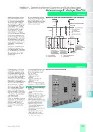
FLENDER-SIMATIC-EHB-Steuerung<br />
Aufbauschema einer Elektrohängebahn mit SIMATIC<br />
EHB-Steuerung und Profibus-DP:<br />
Die Fahrzeugsteuerung für Elektrohängebahnen ist eine<br />
offene Steuerung, die auf SIMATIC-S7-Standardindustriekomponenten<br />
und Profibus DP basiert. Alle Fahrzeugsteuerungen<br />
in einer Anlage kommunizieren über den weltweit<br />
standardisierten Feldbus PROFIBUS-DP mit der überlagerten<br />
Zentral-SPS. Diese übernimmt die Fahrzeugverfolgung und<br />
die Weichensteuerung. Die Profibus-Signale werden für die<br />
Übertragung über Schleifleiter durch einen Signalverstärker<br />
auf ein höheres Spannungsniveau umgeformt und in der<br />
Fahrzeugsteuerung wieder auf Profibusniveau zurückgewandelt.<br />
Die Profibuskommunikation ersetzt die Blockstellensteuerungstechnik<br />
und die dafür erforderlichen<br />
Spezialbaugruppen für die Übertragung pulscodemodulierter<br />
Steuersignale sowie deren aufwendige Verdrahtung. Der Aufwand<br />
für die bislang zeitintensive und fehlerträchtige Planung<br />
und Abstimmung wird erheblich reduziert. Tauschen zentrale<br />
und Fahrzeugsteuerung Daten über einen Feldbus aus, werden<br />
flexiblere Lösungen möglich.<br />
Die Zentralsteuerung gibt den Fahrzeugen ihren Startbefehl<br />
mit Zielangabe und eventuell weitere Informationen via PRO-<br />
FIBUS-DP. Die Fahrzeug-SPS übernimmt danach autonom<br />
die Steuerung des Fahrwagens mit den Funktionen Positionierfahrt,<br />
Geschwindigkeitssteuerung sowie die Abstandsregelung<br />
und den Auffahrtschutz bis das von der Zentral-SPS<br />
vorgegebene Ziel erreicht ist. Optionale Text- oder Bedienpanels<br />
an den Fahrzeugen ermöglichen Bedien- und Beobachtungsfunktionen.<br />
1 - 20<br />
<strong>MOTOX</strong> ® -N<br />
Product description<br />
Flender-SIMATIC overhead monorail vehicle<br />
control system<br />
Schematic view of an overhead automated electrified<br />
monorail with SIMATIC vehicle control system and<br />
Profibus-DP:<br />
The vehicle control system for overhead automated electrified<br />
monorails is an open control system based on SIMATIC standard<br />
industrial components and Profibus-DP. All vehicle control<br />
units in an automated electrified monorail communicate<br />
with the central PLC via the internationally standardized PRO-<br />
FIBUS-DP field bus. The central PLC is responsible for higher<br />
level control such as the vehicle management, higher-level<br />
position tracking and the control of track switch points. The<br />
Profibus signals are converted to a higher voltage level by the<br />
signal amplifier POWER-RAIL-BOOSTER for the transmission<br />
via conductor rails and converted back to the Profibus level<br />
in the vehicle control unit. The Profibus communication replaces<br />
the until the recent past common block station control<br />
technology and the special modules required for the transmission<br />
of the puls-code control signals and their extensive wiring.<br />
The effort expended on what has until now been timeintensive<br />
and fault-prone planning and coordination is considerably<br />
reduced. More flexible solutions become possible<br />
when the central contol system and the vehicle control units<br />
exchange data via field bus.<br />
The central control system transmits to the vehicles the destination<br />
specification, and, if necessary, further information via<br />
PROFIBUS-DP. The intelligent vehicle control PLC enables<br />
functions such as automatic control of position travel, speed<br />
control, distance regulation and collision protection until the<br />
set position is reached. Optional text or control panels on the<br />
vehicles allow control and monitoring functions.
<strong>MOTOX</strong> ® -N<br />
Ein wesentliches Merkmal der Steuerung ist die Möglichkeit<br />
der Fahrzeugpositionierung mittels berührungsloser Identifikationssysteme.<br />
An den gewünschten Stellen der Elektrohängebahn<br />
können Transponder angebracht werden, die ihren<br />
Positionswert an die vorbeifahrende Fahrzeugsteuerung senden.<br />
Ein an der Fahrzeugsteuerung montiertes Lesegerät<br />
empfängt die Daten und überträgt diese an die intelligente<br />
Fahrzeugsteuerung. Diese "virtuellen Schienenschnitte"<br />
ersetzen bei Elektrohängebahnen diejenigen Schienenschnitte,<br />
die alleine für die Positionierung einzelner Fahrzeuge<br />
bei konventioneller Blockstellensteuerung<br />
unumgänglich sind. Dagegen kann über den Profibus-DP<br />
jedes Fahrzeug individuell angesteuert und positioniert werden.<br />
Änderungswünsche lassen sich einfach und flexibel<br />
durch Verschieben oder Montage zusätzlicher Transponder<br />
realisieren. Anstelle von Transpondern für die Positionsübertragung<br />
können auch kontinuierlich und berührungslos messende<br />
herstellerunabhängige Wegerfassungssysteme in das<br />
offene Steuerungskonzept integriert werden.<br />
Durch die Verwendung von Standard-Industrie-Komponenten<br />
auf der Steuerungsseite und der Kommunikation über<br />
den PROFIBUS-DP ergeben sich sowohl für den Anlagenbauer<br />
als auch für den Endkunden entscheidende Vorteile<br />
eines offenen Systems:<br />
An essential feature of the control system is the possibility of<br />
positioning the vehicle by means of contactless identification<br />
systems. Transponders which transmit their position value to<br />
the passing vehicle control system can be attached at desired<br />
positions of the overhead electric monorail. A reading device<br />
mounted on the vehicle control system receives the data and<br />
transmits them to the intelligent vehicle control system. These<br />
"virtual rail sections" on overhead electric monorails replaces<br />
the rail cuttings made for the individual positioning of vehicles<br />
by means of block station control. By contrast, with the Profibus-DP<br />
each vehicle can be individually selected and positioned.<br />
Modification requirements can be met easily and flexibly<br />
by shifting transponders or attaching additional ones. Instead<br />
of transponders for the position transmission, continously and<br />
contactlessly position measuring systems can be integrated<br />
into the open control concept.<br />
By using standard industrial components on the control-system<br />
side and communication via the PROFIBUS-DP the result<br />
is the advantages of an open system which are decisive<br />
both for original equipment manufacturer and end-consumer:<br />
Durchgängige und offene Systemlösung Integrated and open system solution<br />
- Die Fahrzeugsteuerung wird vollständig in die Anlagenautomation<br />
integriert<br />
- Programmierung, Visualisierung und Diagnose sind systemdurchgängig<br />
- Systemleistungen, wie z.B. Profibus-Diagnose Tools und<br />
PROFISave, stehen zur Verfügung<br />
- Der Datenaustausch mit benachbarten Anlagen erfolgt<br />
über DP/DP-Koppler<br />
- Die Fahrzeug-Software auf der Basis von STEP7 ist im<br />
Gegensatz zu proprietären Lösungen transparent und bei<br />
Bedarf durch den Anwender einfach anpassbar an die<br />
Applikation<br />
- The vehicle control system is completely integrated into<br />
the system automation<br />
- Programming, visualisation and diagnosis are system-integrated<br />
- System facilities, such as Profibus diagnostic tools and<br />
PROFISave, are available<br />
- The data exchange with neighbouring systems is effected<br />
via DP/DP coupler<br />
- The vehicle software based on STEP7 is, unlike proprietary<br />
solutions, transparent and, as required, can be easily<br />
adapted to the application by the user<br />
Hohe Flexibilität bei Prozessoptimierung High flexibility combined with process optimisation<br />
- Beliebige Parameter können über Profibus DP schnell<br />
angepasst werden<br />
- Soft- und Hardware der modularen und offenen Steuerung<br />
sind einfach und schnell erweiterbar<br />
- Optional parameters can be rapidly adapted via Profibus<br />
DP<br />
- Soft- and hardware of the modular, open control system<br />
can be easily and rapidly extended<br />
Nutzung von Standardsoftware SIMATIC STEP 7 Use of SIMATIC STEP 7 standard software<br />
Vereinfachte, schnelle und anpassbare Projektierung Simplified, rapid and adaptable project planning<br />
- Das Schienenlayout kann einfacher geplant werden, da<br />
nur für die Positionierung vorgesehene Schienenschnitte<br />
wegfallen. Baumstrukturen im Schienenlayout sind zulässig.<br />
- Auch während der Inbetriebnahme ist nur ein geringer<br />
Änderungsaufwand erforderlich, da im Gegensatz zur<br />
Blockstellensteuerungstechnik keine Verdrahtungsänderungen<br />
an Schienenschnitten mehr erforderlich sind<br />
- The track layout can be planned more easily, as rail cuttings<br />
aren't required any more for the positioning of vehicles.<br />
- Very little expenditure is necessary for modification, including<br />
during start-up, as, unlike with block station control<br />
technology, wiring modifications are no longer necessary<br />
on rail sections<br />
1 - 21
- Die verwendeten Hard- und Softwarebausteine können<br />
über den gesamten Anwendungsbereich standardisiert<br />
werden<br />
- Programmierung und Parametrierung der Fahrzeugsteuerung<br />
erfolgt über den PROFIBUS<br />
1 - 22<br />
<strong>MOTOX</strong> ® -N<br />
- The hard- and software modules used can be standardized<br />
over the entire area of the application<br />
- Programming and parameter setting of the vehicle control<br />
system are effected via the PROFIBUS<br />
Vereinfachte Montage und Inbetriebnahme Simplified installation and start-up<br />
- Durch Wegfall der für die Blockstellensteuerung erfordlichen<br />
Schienenschnitte, Baugruppen und Schaltschränke<br />
und den dafür benötigten Montage- und Verdrahtungsaufwand<br />
wird der gesamte Montage- und Verdrahtungsaufwand<br />
deutlich reduziert<br />
- Fehlerquellen werden durch die Verminderung der Anzahl<br />
benötigter Baugruppen und Klemm stellen reduziert<br />
Hohe Anlagenverfügbarkeit High system availability<br />
- Detaillierte Klartext-Diagnose ist möglich bis zur Sensorik<br />
und Aktorik auf jedem Fahrzeug<br />
- Die Position aller Fahrzeuge kann über HMI (Human Machine<br />
Interface) verfolgt und lokalisiert werden<br />
- Den sofortigen Wiederanlauf nach Spannungsausfall gewährleistet<br />
eine redundante Positions speicherung in der<br />
Zentral- und Fahrzeugsteuerung<br />
- Die Datenübertragung zur Zentralsteuerung erfolgt störsicher<br />
über PROFIBUS<br />
- Einzelne Fahrzeuge oder Fahrzeuggruppen sind im Tipp-<br />
Betrieb über HMI via PROFIBUS steuerbar. Optional können<br />
einzelne Fahrzeuge über eine IR-Schnittstelle gesteuert<br />
werden<br />
- Durch Verwendung von Standardkomponenten sind Ersatzteile<br />
weltweit und schnell verfügbar<br />
- The rail cuttings, control modules and switch cabinets that<br />
have been required for the block station control are not<br />
necessary any more and thus the entire expenditures on<br />
installation and wiring.are considerably reduced.<br />
- Fault sources are reduced due to the reduction in the<br />
number of assemblies and terminal connections required<br />
- Detailed clear-text diagnosis is possible up to the sensing<br />
and actuating equipment on each vehicle<br />
- The position of all the vehicles can be monitored and localised<br />
via HMI (human machine interface)<br />
- Immediate restarting following a power failure is guaranteed<br />
by a redundant position storage system in the central<br />
and vehicle control system<br />
- The interference proof transmission of data to the central<br />
control system is effected via the PROFIBUS<br />
- Individual vehicles or vehicle groups can be controlled in<br />
jogging mode mode by HMI via PROFIBUS. Optionally individual<br />
vehicles can be controlled via an IR interface<br />
- The use of standard components means that spare parts<br />
are rapidly available worldwide
<strong>MOTOX</strong> ® -N<br />
Checkliste Checklist<br />
An<br />
To<br />
Von<br />
From<br />
Flender Tübingen<br />
Bahnhofstr. 40 - 44<br />
D-72072 Tübingen<br />
Tel.: +49 (0)7071/707-0 Telefax: +49 (0)7071/707-400<br />
Fax:<br />
Flender / Tel.: Telefax.:<br />
Fax:<br />
Datum:<br />
Date:<br />
Name:<br />
Projekt:<br />
Project<br />
Firma:<br />
Company<br />
Stückzahl:<br />
No. of pieces:<br />
1. Fahrzeugart<br />
Type of vehicle<br />
(Einzelfahrzeug, Doppelfahrzeug) (single unit, tandem unit)<br />
2.) Einsatzart<br />
Type of application<br />
(Halle; im Freien)<br />
(Interior; open air)<br />
3.) Gewicht des Fahrweks Weight of chassis<br />
4.) Gewicht der Last Weight of load [kg]<br />
5.) Max. Raddruck des Antriebsrads<br />
auf der Schiene<br />
Max. wheel force of driving wheel on rail<br />
6.) Winddruck bei Betrieb im Freien Wind force in case of operation in the open<br />
7.) Laufraddurchmesser Running wheel - diameter<br />
8.) Werkstoff des Laufrads Material of running wheel [Stahl/steel<br />
Vulcolan]<br />
9.) Fahrgeschwindigkeit Driving speed [m/sec]<br />
10.) a) Beschleunigung a) Acceleration<br />
b) Verzögerung b) Deceleration<br />
11.) Radstand Wheel base<br />
12.) max. Steigung Max. slope<br />
13.) min. Kurvenradius Min.radius of curves<br />
14.) Umgebungstemperatur Ambient temperatures<br />
15.) Einschaltungen pro Stunde Cycles per hour<br />
16.) Relative Einschaltdauer Duty type<br />
[kg]<br />
[N]<br />
[N]<br />
[mm]<br />
[m/sec 2 ]<br />
[m/sec 2 ]<br />
[m]<br />
[Grad/degres]<br />
17.) Hand oder Automatikbetrieb<br />
Manual or automatic operating systems<br />
(z.B. freie programmierte Steuerung) (e.g. SPC)<br />
18.) mechanische Bremse Mechanical brake [ja/nein<br />
yes/no]<br />
19.) Zulässiger Bremsweg Permissible braking distance<br />
[mm]<br />
20.) Frequenzumrichterbetrieb Operated by frequency converter [ja/nein<br />
yes/no]<br />
21.) Motorspannung Motor voltage<br />
[V]<br />
22.) Motorschutz mit Wicklungsthermostat Motor protection with coil thermostat (3WTs) or<br />
(3WT´s) oder Motorvollschutz (PTC) thermistor (PTC)<br />
23.) a) Bremsanschlußspannung<br />
a) Operating voltage of brake<br />
(Gleich/Wechslstrom V)<br />
(DC/AC-V)<br />
b)Bremsenabschaltung<br />
(gleichstromseitig / wechselstromseitig)<br />
b) Disconnection of brake on DC/AC-side<br />
24.) Lackierung Painting<br />
25.) Ausführung Design of drive<br />
Falls vorhanden, legen Sie bitte einen Zeichnungsausschnitt bei oder<br />
fertigen Sie umseitig eine Skizze über den vorgesehenen Antrieb an<br />
(von der Arbeitswelle des Getriebemotors zum Laufrad des Wagens).<br />
[m]<br />
[°C]<br />
[c/h]<br />
[%]<br />
[ja/nein<br />
yes/no]<br />
[V]<br />
[DC/AC]<br />
If available, please include a drawing section or prepare drawing of<br />
the planned drive on the back (from the work shaft of the gearmotor to<br />
the running wheel of the vehicle).<br />
1 - 23
<strong>MOTOX</strong> ® -N<br />
Hängebahnantriebe<br />
Monorail conveyor drive<br />
2 - 1
2 - 2<br />
<strong>MOTOX</strong> ® -N
<strong>MOTOX</strong> ® -N<br />
Inhaltsverzeichnis Seite Table of Contents Page<br />
Elektro-Hängebahnantriebe<br />
Typenbezeichnungen 2 - 4<br />
Zulässige Radialkräfte 2 - 6<br />
Leistungsdaten<br />
Für den Leichtlastbereich 2 - 9<br />
Für den Schwerlastbereich 2 - 12<br />
Wirkungsgradtabelle Stirnradschneckengetriebe<br />
Für den Leichtlastbereich 2 - 27<br />
Für den Schwerlastbereich 2 - 29<br />
Momententabellen Kegelstirnradgetriebe<br />
für Antriebsgruppe K4<br />
Für den Leichtlastbereich 2 - 36<br />
Für den Schwerlastbereich 2 - 37<br />
Maßbilder - Übersicht<br />
Für den Leichtlastbereich 2 - 39<br />
Für den Schwerlastbereich 2 - 44<br />
Bauformen<br />
Für den Leichtlastbereich 2 - 57<br />
Für den Schwerlastbereich 2 - 59<br />
Schmierung, Ölmengen 2 - 61<br />
Monorail conveyor drives<br />
Type Designations 2 - 4<br />
Permissible Radial Loads 2 - 6<br />
Performance Data<br />
For the light-duty sector 2 - 9<br />
For the heavy-duty sector 2 - 12<br />
Wirkungsgradtabelle Stirnradschneckengetriebe<br />
For the light-duty sector 2 - 27<br />
For the heavy-duty sector 2 - 29<br />
Torque table Bevel Helical Gear Units<br />
for type of input unit K4<br />
For the light-duty sector 2 - 36<br />
For the heavy-duty sector 2 - 37<br />
Dimension Sheets - Overview<br />
For the light-duty sector 2 - 39<br />
For the heavy-duty sector 2 - 44<br />
Mounting Position 2 - 57<br />
For the light-duty sector 2 - 59<br />
For the heavy-duty sector<br />
Lubrication, Oil Quantities 2 - 61<br />
2 - 3
Typenbezeichnungen Type Designations<br />
Getriebe Gear Units<br />
Typ<br />
Bauart<br />
Größe<br />
Antriebsgruppe<br />
(für Motorbaugröße)<br />
2 - 4<br />
<strong>MOTOX</strong> ® -N<br />
Beispiel: C H F 28 - K4 (100) Example: C H F 28 - K4 (100)<br />
Type<br />
Design<br />
Size<br />
Input unit<br />
(for motor frame size)<br />
Getriebetyp Type of gear unit<br />
C Stirnradschneckengetriebe C Helical Worm Gear Unit<br />
B Kegelstirnradgetriebe, 2-stufig B Bevel Helical Gear Unit, 2-stages<br />
K Kegelstirnradgetriebe, 3-stufig K Bevel Helical Gear Unit, 3-stages<br />
Bauart Design<br />
Branche Branch<br />
H Hängebahnantriebe H Monorail conveyor drives<br />
Befestigung Fixing<br />
F Flanschausführung (A-Typ)<br />
B Fuß- / Flanschausführung<br />
Z Gehäuseflansch (C-Typ)<br />
Antriebsgruppe Type of input unit<br />
K4 Laterne mit Steckwellenverbindung für<br />
IEC-Flanschmotoren<br />
Beispiel:<br />
Example:<br />
CHF 28 K4 (100)<br />
F Flange-mounted (A-type)<br />
B Foot-mounted / Flange-mounted<br />
Z Housing flange (C-type)<br />
K4 Extened housing with shank assembly<br />
for IEC flange mounted motors<br />
mit Motor: CHF 28 - Typenbezeichnung des Motors<br />
with motor:<br />
Type designation of motor
<strong>MOTOX</strong> ® -N<br />
Typenbezeichnungen Type Designations<br />
Motoren Motors<br />
Typ<br />
Baugröße<br />
Polzahl(en)<br />
Besondere Merkmale<br />
Anbaugruppe<br />
Beispiel: M 100L 4/2 R - L16 NH Example: M 100L 4/2 R - L16 NH<br />
Type<br />
Size<br />
Number(s) of poles<br />
Motor features<br />
Add. feature unit<br />
Motortypen Types of motors<br />
M<br />
Drehstrommotor<br />
MB<br />
Einphasenmotor mit Betriebskondensator<br />
MK<br />
Einphasenmotor mit Betriebs- und Anlaufkondensator und<br />
Startrelais<br />
M<br />
Three phase motor<br />
Besondere Merkmale Motor features<br />
R Widerstandsläufer<br />
F Fremdbelüftung<br />
U Unbelüftet<br />
I Schwungradlüfter<br />
W Schutzdach<br />
H Verminderter Geräuschpegel<br />
M <strong>MOTOX</strong> ® -Master (Integrierter Frequenzumrichter)<br />
IN Inkrementalgeber<br />
MB<br />
Single phase motor with running capacitor<br />
Anbaugruppe Additional feature unit<br />
L<br />
Federdruck-Einscheibenbremse, gleichstromerregt<br />
16 Größe = Brems-Nennmoment<br />
16/.. Eingestelltes Bremsmoment<br />
N Normalausführung<br />
G Gekapselte Ausführung<br />
MK<br />
Single phase motor with running and starting capacitor and<br />
starting relais<br />
R Resistance rotor<br />
F Forced cooling<br />
U Non ventilated<br />
I High inertia fan<br />
W Rain cover<br />
H Reduced noise level<br />
M <strong>MOTOX</strong> ® -Master (Integral Frequency Inverters)<br />
IN Incremental encoder<br />
L<br />
Spring loaded-single disk brake, DC-exitation<br />
16 Size = Nominal torque of brake<br />
16/.. Adjusted braking torque<br />
N Normal design<br />
G Encapsulated design<br />
H Handlüftung H Manual release<br />
Beispiel:<br />
Example:<br />
M 100 L 4/2 R - L16NH<br />
2 - 5
2 - 6<br />
<strong>MOTOX</strong> ® -N<br />
Zulässige Radialkräfte bei Betriebsfaktor f B=1 Permissible overhung loads at service factor f B=1<br />
für Hängebahnantriebe for monorail conveyor drives<br />
ød<br />
Berechnung nach Lagerlebensdauer Calculation based on bearing life<br />
F xzul1<br />
Berechnung auf Festigkeit Calculation based on mechanical strength<br />
F xzul2<br />
Zulässig ist der kleinste Wert F xzul. , der sich bei der Berechnung<br />
nach den 2 Kriterien ergibt. Reichen die Tabellenwerte<br />
nicht aus, erbitten wir Rückfrage mit folgenden Angaben zur<br />
Radialkraft:<br />
- Größe<br />
- Richtung / Angriffswinkel<br />
- Angriffspunkt (x) an der Welle<br />
- Drehrichtung der Welle<br />
F xzul F Rzul<br />
x l x l/2 0<br />
F<br />
F Rzul<br />
F xzul<br />
y<br />
= FRzul ⋅ ------------ [ N ]<br />
z+ x<br />
a<br />
= ------------ [<br />
kN]<br />
b+ x<br />
0<br />
The lower value F xzul. of both calculation results is the<br />
permissible overhung load. If values on tables aren’t sufficient<br />
for requirement, please consult the office-staff,<br />
stating following criteria on overhung load:<br />
- value<br />
- direction / angle of force<br />
- location (x) on shaft<br />
- direction of rotation of shaft
<strong>MOTOX</strong> ® -N<br />
Standardlagerung für Leichtlast Standard Bearings for the light-duty sector<br />
Typ(e)<br />
d<br />
[mm]<br />
l<br />
[mm]<br />
y<br />
[mm]<br />
z<br />
[mm]<br />
a<br />
[kNmm]<br />
b<br />
[mm]<br />
≤ 16<br />
[min -1 ]<br />
FRzul in N mit x= l/2 für Abtriebsdrehzahlen n2 in min -1<br />
FRzul in N for x = l/2 for output speeds n2 in min -1<br />
≤ 25<br />
[min -1 ]<br />
≤ 40<br />
[min -1 ]<br />
≤ 63<br />
[min -1 ]<br />
≤ 100<br />
[min -1 ]<br />
≤ 160<br />
[min -1 ]<br />
CHF28 20/25 35 147 134 344500 40 6500 6500 6500 5935 5153 4443 4120<br />
BH.38 * 25 35 170 157 600000 47 10000 10000 10000 10000 10000 9581 8327<br />
* Werte für Lage der Abtriebswelle B-Seite, auf Anfrage * Values for position for output shaft on B side, on request<br />
Standardlagerung für Schwerlast Standard Bearings for the heavy-duty sector<br />
Typ(e)<br />
Flansch<br />
Flange<br />
d<br />
[mm]<br />
l<br />
[mm]<br />
y<br />
[mm]<br />
z<br />
[mm]<br />
a<br />
[kNmm]<br />
b<br />
[mm]<br />
≤ 16<br />
[min -1 ]<br />
F Rzul in N mit x= l/2 für Abtriebsdrehzahlen n 2 in min -1<br />
F Rzul in N for x = l/2 for output speeds n 2 in min -1<br />
≤ 25<br />
[min -1 ]<br />
≤ 40<br />
[min -1 ]<br />
≤ 63<br />
[min -1 ]<br />
≤ 100<br />
[min -1 ]<br />
≤ 160<br />
[min -1 ]<br />
≤ 250<br />
[min -1 ]<br />
≤ 250<br />
[min -1 ]<br />
CHZ48 C140 35 70 179 151 988000 48 13000 13000 13000 13000 13000 13000 13000<br />
CHF48<br />
CHF68<br />
C250S/L 35 70 203 175 504000 0 18000 18000 18000 18000 18000 15995 14818<br />
Q203 55 72 286 258 1480000 46 20000 20000 20000 20000 20000 20000 20000<br />
C250L 45 90 252 224 980000 0 35000 35000 35000 29860 25723 23122 19462<br />
Q203 55 72 313 285 2960000 46 40000 40000 40000 36188 31232 27917 23498<br />
KHZ48 C140 35 70 179 151 988000 48 13000 13000 13000 13000 13000 13000 13000<br />
KHF48<br />
KHF68<br />
C250S/L 35 70 203 175 504000 0 18000 18000 18000 18000 18000 15995 14818<br />
Q203 55 72 286 258 1480000 46 20000 20000 20000 20000 20000 20000 20000<br />
C250L 45 90 252 224 980000 0 35000 35000 35000 29860 25723 23122 19462<br />
Q203 55 72 313 285 2960000 46 40000 40000 40000 36188 31232 27917 23498<br />
2 - 7
Leistungsdaten<br />
für Leicht- und Schwerlastbereich<br />
2 - 8<br />
<strong>MOTOX</strong> ® -N<br />
Performance Data<br />
for the light-duty and heavy-duty sector<br />
Legende / Erläuterungen Legend / Explanations<br />
P Motor = Bemessungsleistung des Antriebsmotors P Motor = Rated power of motor<br />
(50Hz) = bei Netzfrequenz 50 Hz<br />
(60Hz) = bei Netzfrequenz 60 Hz<br />
(50Hz) = at mains frequency 50Hz<br />
(60Hz) = at mains frequency 60Hz<br />
n 2 = Abtriebsdrehzahl des Getriebes n 2 = Output speed of gear unit<br />
(50Hz) = bei Netzfrequenz 50 Hz<br />
(60Hz) = bei Netzfrequenz 60 Hz<br />
(50Hz) = at mains frequency 50Hz<br />
(60Hz) = at mains frequency 60Hz<br />
T 2 = Abtriebsdrehmoment des Getriebes T 2 = Output torque of gear unit<br />
f B = Betriebsfaktor des Antriebs f B = Service factor of the drive<br />
i ges = Gesamtübersetzung des Getriebes i ges = Total ratio of the gear unit<br />
= Übersetzung gehört zur Vorzugsreihe von<br />
<strong>MOTOX</strong> ® -N<br />
Vorzugsreihe Prefered list<br />
Die Vorzugsreihe bietet sehr kurze Lieferzeiten durch höchste<br />
Verfügbarkeit.<br />
= Ratio belonging to preferred list of<br />
<strong>MOTOX</strong> ® -N<br />
The preferred list offers very short term delivery through highest<br />
availability.
<strong>MOTOX</strong> ® -N<br />
Leistungsdaten für den Leichtlastbereich<br />
nach VDI-Richtlinie 3643<br />
Performance Data for the light-duty sector<br />
to VDI Guideline 3643<br />
Legende / Erläuterungen siehe Seite 2 - 8 Legend / explanations see page 2 - 8<br />
Maßbilder-Übersicht siehe Seite 2 - 40 Dimension Sheets Overview see page 2 - 40<br />
PMotor [kW]<br />
0,12 (50Hz)<br />
0,14 (60Hz)<br />
0,18 (50Hz)<br />
0,22 (60Hz)<br />
0,25 (50Hz)<br />
0,3 (60Hz)<br />
n 2 (50Hz)<br />
[min -1 ]<br />
n 2 (60Hz)<br />
[min -1 ]<br />
T 2<br />
[Nm]<br />
f B<br />
[-]<br />
i ges<br />
[-]<br />
Getriebemotor<br />
Gear Motor<br />
22 26 47 4,26 63,92 BH.38-M71B4<br />
26 31 40 5,1 53,9<br />
30 36 35 5,7 47,86<br />
19,2 23 43 2,33 73,85 CH.28-M71B4<br />
23 28 35 2,82 61,01<br />
29 35 28 3,23 49,01<br />
38 46 25 4,04 36,92<br />
47 56 20 4,89 30,5<br />
58 70 17 5,7 24,62<br />
22 26 71 2,8 63,92 BH.38-M71C4<br />
26 31 60 3,32 53,9<br />
29 35 53 3,74 47,86<br />
33 40 47 4,27 41,96<br />
37 44 42 4,77 37,55<br />
42 50 37 5,4 33,33<br />
19 23 65 1,53 73,85 CH.28-M71C4<br />
23 28 54 1,85 61,01<br />
29 35 43 2,12 49,01<br />
38 46 38 2,66 36,92<br />
46 55 31 3,22 30,5<br />
57 68 27 3,76 24,62<br />
69 83 22 4,41 20,34<br />
86 103 18 5,1 16,34<br />
110 132 14 5,2 12,78<br />
137 164 11 5,2 10,24<br />
172 206 9 5,2 8,13<br />
22 26 100 2 63,92 BH.38-M71S4<br />
26 31 84 2,37 53,9<br />
29 35 75 2,67 47,86<br />
33 40 66 3,05 41,96<br />
37 44 59 3,41 37,55<br />
42 50 52 3,84 33,33<br />
48 58 46 4,38 29,2<br />
54 65 40 4,78 25,68<br />
60 72 36 5,1 23,2<br />
69 83 32 5,6 20,21<br />
18,8 23 91 1,09 73,85 CH.28-M71S4<br />
23 28 75 1,33 61,01<br />
28 34 61 1,52 49,01<br />
38 46 53 1,9 36,92<br />
46 55 43 2,3 30,5<br />
56 67 37 2,69 24,62<br />
68 82 31 3,16 20,34<br />
85 102 25 3,64 16,34<br />
109 131 19 3,73 12,78<br />
136 163 15 3,68 10,24<br />
171 205 12 3,74 8,13<br />
2 - 9
Legende / Erläuterungen siehe Seite 2 - 8 Legend / explanations see page 2 - 8<br />
Maßbilder-Übersicht siehe Seite 2 - 40 Dimension Sheets Overview see page 2 - 40<br />
P Motor<br />
[kW]<br />
0,37 (50Hz)<br />
0,44 (60Hz)<br />
0,55 (50Hz)<br />
0,66 (60Hz)<br />
2 - 10<br />
n 2 (50Hz)<br />
[min -1 ]<br />
n 2 (60Hz)<br />
[min -1 ]<br />
T 2<br />
[Nm]<br />
f B<br />
[-]<br />
<strong>MOTOX</strong> ® -N<br />
22 26 148 1,35 63,92 BH.38-M71M4<br />
26 31 125 1,6 53,9<br />
29 35 111 1,81 47,86<br />
33 40 97 2,06 41,96<br />
37 44 87 2,3 37,55<br />
42 50 77 2,59 33,33<br />
48 58 68 2,96 29,2<br />
54 65 59 3,23 25,68<br />
60 72 54 3,47 23,2<br />
69 83 47 3,79 20,21<br />
77 92 42 4,07 18,16<br />
85 102 38 4,35 16,39<br />
94 113 34 4,65 14,86<br />
103 124 31 4,96 13,52<br />
116 139 28 5,4 11,96<br />
126 151 26 5,7 11,04<br />
23 28 112 0,9 61,01 CH.28-M71M4<br />
28 34 90 1,03 49,01<br />
38 46 78 1,28 36,92<br />
46 55 64 1,55 30,5<br />
56 67 55 1,82 24,62<br />
68 82 46 2,13 20,34<br />
85 102 37 2,46 16,34<br />
109 131 29 2,52 12,78<br />
136 163 23 2,49 10,24<br />
171 205 18 2,53 8,13<br />
26 31 184 1,09 53,9 BH.38-M71MB4<br />
29 35 163 1,22 47,86<br />
33 40 143 1,4 41,96<br />
37 44 128 1,56 37,55<br />
42 50 114 1,76 33,33<br />
48 58 100 2,01 29,2<br />
55 66 88 2,19 25,68<br />
60 72 79 2,35 23,2<br />
69 83 69 2,57 20,21<br />
77 92 62 2,76 18,16<br />
85 102 56 2,95 16,39<br />
94 113 51 3,15 14,86<br />
104 125 46 3,36 13,52<br />
117 140 41 3,65 11,96<br />
127 152 38 3,85 11,04<br />
147 176 32 4,25 9,51<br />
162 194 29 4,58 8,64<br />
57 68 81 1,23 24,62 CH.28-M71MB4<br />
69 83 67 1,44 20,34<br />
86 103 54 1,67 16,34<br />
110 132 42 1,71 12,78<br />
137 164 34 1,69 10,24<br />
172 206 27 1,71 8,13<br />
i ges<br />
[-]<br />
Getriebemotor<br />
Gear Motor
<strong>MOTOX</strong> ® -N<br />
Legende / Erläuterungen siehe Seite 2 - 8 Legend / explanations see page 2 - 8<br />
Maßbilder-Übersicht siehe Seite 2 - 40 Dimension Sheets Overview see page 2 - 40<br />
P Motor<br />
[kW]<br />
0,75 (50Hz)<br />
0,9 (60Hz)<br />
1,1 (50Hz)<br />
1,3 (60Hz)<br />
1,5 (50Hz)<br />
1,8 (60Hz)<br />
2,2 (50Hz)<br />
2,6 (60Hz)<br />
3 (50Hz)<br />
3,6 (60Hz)<br />
n 2 (50Hz)<br />
[min -1 ]<br />
n 2 (60Hz)<br />
[min -1 ]<br />
T 2<br />
[Nm]<br />
f B<br />
[-]<br />
29 35 223 0,9 47,86 BH.38-M80M4<br />
33 40 195 1,02 41,96<br />
37 44 175 1,14 37,55<br />
42 50 155 1,29 33,33<br />
48 58 136 1,47 29,2<br />
55 66 120 1,61 25,68<br />
60 72 108 1,72 23,2<br />
69 83 94 1,88 20,21<br />
77 92 85 2,02 18,16<br />
85 102 76 2,16 16,39<br />
94 113 69 2,31 14,86<br />
104 125 63 2,46 13,52<br />
117 140 56 2,68 11,96<br />
127 152 51 2,82 11,04<br />
147 176 44 3,12 9,51<br />
162 194 40 3,36 8,64<br />
57 68 111 0,9 24,62 CH.28-M80M4<br />
69 83 92 1,06 20,34<br />
86 103 74 1,22 16,34<br />
110 132 58 1,25 12,78<br />
137 164 46 1,24 10,24<br />
172 206 37 1,26 8,13<br />
42 50 226 0,89 33,33 BH.38-M90S4<br />
48 58 198 1,01 29,2<br />
55 66 174 1,1 25,68<br />
61 73 157 1,18 23,2<br />
70 84 137 1,29 20,21<br />
78 94 123 1,39 18,16<br />
86 103 111 1,48 16,39<br />
95 114 101 1,59 14,86<br />
104 125 92 1,69 13,52<br />
118 142 81 1,84 11,96<br />
128 154 75 1,94 11,04<br />
148 178 64 2,14 9,51<br />
163 196 59 2,3 8,64<br />
55 66 239 0,8 25,68 BH.38-M90L4<br />
60 72 216 0,86 23,2<br />
69 83 188 0,94 20,21<br />
77 92 169 1,01 18,16<br />
85 102 153 1,08 16,39<br />
94 113 138 1,16 14,86<br />
104 125 126 1,23 13,52<br />
117 140 111 1,34 11,96<br />
127 152 103 1,41 11,04<br />
147 176 89 1,56 9,51<br />
162 194 80 1,68 8,64<br />
105 126 182 0,85 13,52 BH.38-M100L4<br />
119 143 161 0,93 11,96<br />
129 155 149 0,98 11,04<br />
149 179 128 1,08 9,51<br />
164 197 116 1,16 8,64<br />
166 199 158 0,86 8,64 BH.38-M100LB4<br />
i ges<br />
[-]<br />
Getriebemotor<br />
Gear Motor<br />
2 - 11
2 - 12<br />
<strong>MOTOX</strong> ® -N<br />
Leistungsdaten für den Schwerlastbereich Performance Data for the heavy-duty sector<br />
Legende / Erläuterungen siehe Seite 2 - 8 Legend / explanations see page 2 - 8<br />
Maßbilder-Übersicht siehe Seite 2 - 41 Dimension Sheets Overview see page 2 - 41<br />
PMotor [kW]<br />
0,12 (50Hz)<br />
0,14 (60Hz)<br />
0,18 (50Hz)<br />
0,22 (60Hz)<br />
n 2 (50Hz)<br />
[min -1 ]<br />
n 2 (60Hz)<br />
[min -1 ]<br />
T 2<br />
[Nm]<br />
f B<br />
[-]<br />
i ges<br />
[-]<br />
Getriebemotor<br />
Gear Motor<br />
5,8 7 197 4,17 243,72 KH.68-M71B4<br />
6,6 7,9 174 4,71 215,68 <br />
7,2 8,6 158 5,2 196,07<br />
8,1 9,7 142 5,8 176,14 <br />
8,4 10,1 137 3,29 169,53 KH.48-M71B4<br />
9,4 11,3 122 3,7 150,76<br />
10,9 13,1 106 4,26 130,78 <br />
11,6 13,9 99 4,56 122,19<br />
13,2 15,8 87 5,2 107,47 <br />
15,1 18,1 76 5,9 94,12<br />
3,9 4,7 193 3,53 364 CH.68-M71B4<br />
4,4 5,3 174 3,91 323,7<br />
5,1 6,1 154 4,42 280,8 <br />
5,4 6,5 145 4,7 262,36<br />
6,2 7,4 130 5,3 230,75 <br />
7 8,4 115 5,9 202,09<br />
4,4 5,3 168 2,2 320,67 CH.48-M71B4<br />
5 6 151 2,44 284,7<br />
5,7 6,8 135 2,74 249,6 <br />
6,4 7,7 122 3,03 223,36<br />
7,2 8,6 110 3,38 198,25 <br />
8,2 9,8 97 3,84 173,73<br />
9,3 11,2 86 4,34 152,75 <br />
10,3 12,4 78 4,8 138<br />
11,8 14,2 68 5,5 120,25 <br />
5,7 6,8 299 2,74 243,72 KH.68-M71C4<br />
6,5 7,8 265 3,1 215,68 <br />
7,1 8,5 241 3,41 196,07<br />
7,9 9,5 216 3,79 176,14 <br />
9,3 11,2 185 4,42 150,98<br />
10,2 12,2 168 4,89 136,6 <br />
11,1 13,3 155 5,3 126,09<br />
8,3 10 208 2,16 169,53 KH.48-M71C4<br />
9,3 11,2 185 2,43 150,76<br />
10,7 12,8 161 2,8 130,78 <br />
11,5 13,8 150 3 122,19<br />
13 15,6 132 3,41 107,47 <br />
14,9 17,9 116 3,89 94,12<br />
16,8 20 102 4,4 83,25 <br />
18,6 22 93 4,86 75,45<br />
21 25 82 5,5 66,6 <br />
3,8 4,6 293 2,33 364 CH.68-M71C4<br />
4,3 5,2 265 2,57 323,7<br />
5 6 234 2,91 280,8 <br />
5,3 6,4 221 3,09 262,36<br />
6,1 7,3 197 3,47 230,75 <br />
6,9 8,3 175 3,87 202,09<br />
7,8 9,4 156 4,18 178,75 <br />
8,6 10,3 142 4,44 162<br />
9,8 11,8 127 4,8 143 <br />
10,9 13,1 115 5,1 129<br />
12 14,4 104 5,5 117 <br />
13,1 15,7 95 5,8 106,6
<strong>MOTOX</strong> ® -N<br />
Legende / Erläuterungen siehe Seite 2 - 8 Legend / explanations see page 2 - 8<br />
Maßbilder-Übersicht siehe Seite 2 - 41 Dimension Sheets Overview see page 2 - 41<br />
P Motor<br />
[kW]<br />
0,18 (50Hz)<br />
0,22 (60Hz)<br />
0,25 (50Hz)<br />
0,3 (60Hz)<br />
n 2 (50Hz)<br />
[min -1 ]<br />
n 2 (60Hz)<br />
[min -1 ]<br />
T 2<br />
[Nm]<br />
f B<br />
[-]<br />
4,4 5,3 255 1,45 320,67 CH.48-M71C4<br />
4,9 5,9 230 1,61 284,7<br />
5,6 6,7 205 1,8 249,6 <br />
6,3 7,6 186 2 223,36<br />
7,1 8,5 167 2,23 198,25 <br />
8,1 9,7 148 2,52 173,73<br />
9,2 11 131 2,86 152,75 <br />
10,1 12,1 119 3,15 138<br />
11,6 13,9 104 3,62 120,25 <br />
13 15,6 94 4 108<br />
14,4 17,3 85 4,29 97,5 <br />
15,8 19 77 4,59 88,4<br />
17,4 21 70 4,89 80,44 <br />
19,7 24 62 5,3 71,12<br />
21 25 57 5,6 65,68 <br />
30 36 50 5,7 46,93 <br />
5,7 6,8 419 1,96 243,72 KH.68-M71S4<br />
6,4 7,7 370 2,21 215,68 <br />
7,1 8,5 337 2,43 196,07<br />
7,9 9,5 303 2,71 176,14 <br />
9,2 11 259 3,16 150,98<br />
10,2 12,2 235 3,49 136,6 <br />
11 13,2 217 3,79 126,09<br />
12,7 15,2 188 4,35 109,64 <br />
14 16,8 171 4,8 99,55<br />
15,3 18,4 156 5,3 90,89 <br />
16,7 20 143 5,7 83,4<br />
8,2 9,8 291 1,55 169,53 KH.48-M71S4<br />
9,2 11 259 1,74 150,76<br />
10,6 12,7 225 2 130,78 <br />
11,4 13,7 210 2,14 122,19<br />
12,9 15,5 185 2,44 107,47 <br />
14,8 17,8 162 2,78 94,12<br />
16,7 20 143 3,15 83,25 <br />
18,4 22 130 3,47 75,45<br />
21 25 114 3,93 66,6 <br />
23 28 103 4,36 60,08<br />
26 31 94 4,81 54,49 <br />
28 34 85 5,3 49,65<br />
31 37 78 5,8 45,41 <br />
3,8 4,6 409 1,66 364 CH.68-M71S4<br />
4,3 5,2 370 1,84 323,7<br />
5 6 327 2,08 280,8 <br />
5,3 6,4 309 2,21 262,36<br />
6 7,2 275 2,48 230,75 <br />
6,9 8,3 244 2,78 202,09<br />
7,8 9,4 218 2,99 178,75 <br />
8,6 10,3 199 3,18 162<br />
9,7 11,6 177 3,44 143 <br />
10,8 13 160 3,68 129<br />
11,9 14,3 146 3,92 117 <br />
13 15,6 133 4,17 106,6<br />
14,3 17,2 122 4,43 97,5 <br />
15,4 18,5 131 4,62 90 <br />
i ges<br />
[-]<br />
Getriebemotor<br />
Gear Motor<br />
2 - 13
Legende / Erläuterungen siehe Seite 2 - 8 Legend / explanations see page 2 - 8<br />
Maßbilder-Übersicht siehe Seite 2 - 41 Dimension Sheets Overview see page 2 - 41<br />
P Motor<br />
[kW]<br />
0,25 (50Hz)<br />
0,3 (60Hz)<br />
0,37 (50Hz)<br />
0,44 (60Hz)<br />
2 - 14<br />
n 2 (50Hz)<br />
[min -1 ]<br />
n 2 (60Hz)<br />
[min -1 ]<br />
T 2<br />
[Nm]<br />
f B<br />
[-]<br />
<strong>MOTOX</strong> ® -N<br />
16,5 19,8 123 5 84,09 CH.68-M71S4<br />
18,8 23 109 5,5 73,96 <br />
4,3 5,2 356 1,04 320,67 CH.48-M71S4<br />
4,9 5,9 321 1,15 284,7<br />
5,6 6,7 287 1,29 249,6 <br />
6,2 7,4 260 1,43 223,36<br />
7 8,4 233 1,59 198,25 <br />
8 9,6 207 1,8 173,73<br />
9,1 10,9 183 2,04 152,75 <br />
10,1 12,1 166 2,25 138<br />
11,6 13,9 146 2,59 120,25 <br />
12,9 15,5 131 2,87 108<br />
14,3 17,2 119 3,08 97,5 <br />
15,7 18,8 108 3,29 88,4<br />
17,3 21 98 3,51 80,44 <br />
19,5 23 87 3,81 71,12<br />
21 25 80 4,02 65,68 <br />
25 30 69 4,45 56,55<br />
27 32 63 4,75 51,41 <br />
30 36 69 4,08 46,93 <br />
33 40 63 4,95 42<br />
37 44 56 4,66 37,28 <br />
43 52 49 5,3 32,67<br />
5,7 6,8 620 1,32 243,72 KH.68-M71M4<br />
6,4 7,7 548 1,5 215,68 <br />
7,1 8,5 498 1,65 196,07<br />
7,9 9,5 448 1,83 176,14 <br />
9,2 11 384 2,14 150,98<br />
10,2 12,2 347 2,36 136,6 <br />
11 13,2 321 2,56 126,09<br />
12,7 15,2 279 2,94 109,64 <br />
14 16,8 253 3,24 99,55<br />
15,3 18,4 231 3,55 90,89 <br />
16,7 20 212 3,87 83,4<br />
18,1 22 195 4,2 76,84 <br />
19,9 24 177 4,62 69,78<br />
22 26 162 5,1 63,57 <br />
24 29 148 5,5 58,23<br />
8,2 9,8 431 1,04 169,53 KH.48-M71M4<br />
9,2 11 383 1,17 150,76<br />
10,6 12,7 332 1,35 130,78 <br />
11,4 13,7 311 1,45 122,19<br />
12,9 15,5 273 1,65 107,47 <br />
14,8 17,8 239 1,88 94,12<br />
16,7 20 212 2,13 83,25 <br />
18,4 22 192 2,35 75,45<br />
21 25 169 2,66 66,6 <br />
23 28 153 2,95 60,08<br />
26 31 139 3,25 54,49 <br />
28 34 126 3,57 49,65<br />
31 37 115 3,9 45,41 <br />
34 41 103 4,36 40,6<br />
37 44 95 4,75 37,28 <br />
41 49 85 5,3 33,6<br />
i ges<br />
[-]<br />
Getriebemotor<br />
Gear Motor
<strong>MOTOX</strong> ® -N<br />
Legende / Erläuterungen siehe Seite 2 - 8 Legend / explanations see page 2 - 8<br />
Maßbilder-Übersicht siehe Seite 2 - 41 Dimension Sheets Overview see page 2 - 41<br />
P Motor<br />
[kW]<br />
0,37 (50Hz)<br />
0,44 (60Hz)<br />
0,55 (50Hz)<br />
0,66 (60Hz)<br />
n 2 (50Hz)<br />
[min -1 ]<br />
n 2 (60Hz)<br />
[min -1 ]<br />
T 2<br />
[Nm]<br />
f B<br />
[-]<br />
3,8 4,6 605 1,12 364 CH.68-M71M4<br />
4,3 5,2 547 1,24 323,7<br />
5 6 484 1,41 280,8 <br />
5,3 6,4 457 1,5 262,36<br />
6 7,2 408 1,68 230,75 <br />
6,9 8,3 362 1,88 202,09<br />
7,8 9,4 323 2,02 178,75 <br />
8,6 10,3 295 2,15 162<br />
9,7 11,6 262 2,33 143 <br />
10,8 13 237 2,49 129<br />
11,9 14,3 216 2,65 117 <br />
13 15,6 197 2,82 106,6<br />
14,3 17,2 180 2,99 97,5 <br />
15,4 18,5 193 3,12 90 <br />
16,5 19,8 181 3,4 84,09<br />
18,8 23 161 3,7 73,96 <br />
21 25 142 4,41 64,77<br />
24 29 126 5,2 57,29 <br />
27 32 115 5,6 51,92<br />
37 44 86 5 38<br />
41 49 76 5,7 33,61 <br />
46 55 69 5,7 30,46<br />
5,6 6,7 424 0,87 249,6 CH.48-M71M4<br />
6,2 7,4 385 0,96 223,36<br />
7 8,4 346 1,08 198,25 <br />
8 9,6 306 1,22 173,73<br />
9,1 10,9 271 1,38 152,75 <br />
10,1 12,1 246 1,52 138<br />
11,6 13,9 216 1,75 120,25 <br />
12,9 15,5 194 1,94 108<br />
14,3 17,2 175 2,08 97,5 <br />
15,7 18,8 159 2,22 88,4<br />
17,3 21 145 2,37 80,44 <br />
19,5 23 128 2,58 71,12<br />
21 25 118 2,71 65,68 <br />
25 30 102 3,01 56,55<br />
27 32 93 3,21 51,41 <br />
30 36 103 2,75 46,93 <br />
33 40 93 3,34 42<br />
37 44 83 3,15 37,28 <br />
43 52 73 3,58 32,67<br />
48 58 64 4,41 28,72 <br />
54 65 58 4,68 25,95<br />
61 73 51 5,2 22,61 <br />
5,7 6,8 921 0,89 243,72 KH.68-M71MB4<br />
6,4 7,7 815 1,01 215,68 <br />
7,1 8,5 741 1,11 196,07<br />
7,9 9,5 666 1,23 176,14 <br />
9,2 11 571 1,44 150,98<br />
10,2 12,2 516 1,59 136,6 <br />
11 13,2 476 1,72 126,09<br />
12,7 15,2 414 1,98 109,64 <br />
14 16,8 376 2,18 99,55<br />
15,3 18,4 343 2,39 90,89 <br />
i ges<br />
[-]<br />
Getriebemotor<br />
Gear Motor<br />
2 - 15
Legende / Erläuterungen siehe Seite 2 - 8 Legend / explanations see page 2 - 8<br />
Maßbilder-Übersicht siehe Seite 2 - 41 Dimension Sheets Overview see page 2 - 41<br />
P Motor<br />
[kW]<br />
0,55 (50Hz)<br />
0,66 (60Hz)<br />
2 - 16<br />
n 2 (50Hz)<br />
[min -1 ]<br />
n 2 (60Hz)<br />
[min -1 ]<br />
T 2<br />
[Nm]<br />
f B<br />
[-]<br />
<strong>MOTOX</strong> ® -N<br />
16,7 20 315 2,6 83,4 KH.68-M71MB4<br />
18,1 22 290 2,82 76,84 <br />
19,9 24 264 3,11 69,78<br />
22 26 240 3,41 63,57 <br />
24 29 220 3,73 58,23<br />
27 32 196 4,18 51,96 <br />
10,6 12,7 494 0,91 130,78 KH.48-M71MB4<br />
11,4 13,7 462 0,97 122,19<br />
12,9 15,5 406 1,11 107,47 <br />
14,8 17,8 356 1,27 94,12<br />
16,7 20 315 1,43 83,25 <br />
18,4 22 285 1,58 75,45<br />
21 25 252 1,79 66,6 <br />
23 28 227 1,98 60,08<br />
26 31 206 2,19 54,49 <br />
28 34 188 2,4 49,65<br />
31 37 172 2,62 45,41 <br />
34 41 153 2,93 40,6<br />
37 44 141 3,19 37,28 <br />
41 49 127 3,54 33,6<br />
48 58 109 4,12 28,9 <br />
50 60 104 4,32 27,55 <br />
56 67 94 4,79 24,85<br />
62 74 85 5,3 22,54 <br />
68 82 78 5,8 20,54<br />
4,3 5,2 809 0,84 323,7 CH.68-M71MB4<br />
5 6 716 0,95 280,8 <br />
5,3 6,4 675 1,01 262,36<br />
6,1 7,3 602 1,14 230,75 <br />
6,9 8,3 534 1,27 202,09<br />
7,8 9,4 477 1,37 178,75 <br />
8,6 10,3 435 1,45 162<br />
9,8 11,8 387 1,57 143 <br />
10,9 13,1 350 1,68 129<br />
12 14,4 318 1,79 117 <br />
13,1 15,7 291 1,9 106,6<br />
14,4 17,3 266 2,02 97,5 <br />
15,6 18,7 285 2,12 90 <br />
16,6 19,9 268 2,3 84,09<br />
18,9 23 237 2,51 73,96 <br />
22 26 209 2,99 64,77<br />
24 29 186 3,52 57,29 <br />
27 32 169 3,76 51,92<br />
31 37 150 4,08 45,83 <br />
34 41 135 4,38 41,35<br />
37 44 126 3,41 38<br />
37 44 123 4,68 37,5 <br />
41 49 112 4,99 34,17<br />
42 50 112 3,84 33,61 <br />
45 54 103 5,3 31,25 <br />
46 55 101 3,84 30,46<br />
50 60 92 5,7 27,94<br />
52 62 89 4,48 26,89 <br />
58 70 81 4,9 24,26<br />
64 77 73 5,8 22 <br />
i ges<br />
[-]<br />
Getriebemotor<br />
Gear Motor
<strong>MOTOX</strong> ® -N<br />
Legende / Erläuterungen siehe Seite 2 - 8 Legend / explanations see page 2 - 8<br />
Maßbilder-Übersicht siehe Seite 2 - 41 Dimension Sheets Overview see page 2 - 41<br />
P Motor<br />
[kW]<br />
0,55 (50Hz)<br />
0,66 (60Hz)<br />
0,75 (50Hz)<br />
0,9 (60Hz)<br />
n 2 (50Hz)<br />
[min -1 ]<br />
n 2 (60Hz)<br />
[min -1 ]<br />
T 2<br />
[Nm]<br />
f B<br />
[-]<br />
8,1 9,7 452 0,83 173,73 CH.48-M71MB4<br />
9,2 11 400 0,93 152,75 <br />
10,1 12,1 362 1,03 138<br />
11,6 13,9 318 1,19 120,25 <br />
13 15,6 286 1,31 108<br />
14,4 17,3 259 1,41 97,5 <br />
15,8 19 235 1,5 88,4<br />
17,4 21 214 1,6 80,44 <br />
19,7 24 189 1,74 71,12<br />
21 25 175 1,83 65,68 <br />
25 30 150 2,03 56,55<br />
27 32 137 2,17 51,41 <br />
30 36 152 1,87 46,93 <br />
33 40 137 2,27 42<br />
38 46 122 2,13 37,28 <br />
43 52 108 2,43 32,67<br />
49 59 95 2,99 28,72 <br />
54 65 86 3,17 25,95<br />
62 74 75 3,54 22,61 <br />
69 83 67 4,1 20,31<br />
76 91 61 4,85 18,33 <br />
84 101 55 5,2 16,62<br />
93 112 50 5,2 15,13 <br />
105 126 44 5,2 13,37<br />
113 136 41 6 12,35 <br />
7,1 8,5 1003 0,82 196,07 KH.68-M80M4<br />
7,9 9,5 901 0,91 176,14 <br />
9,3 11,2 772 1,06 150,98<br />
10,2 12,2 699 1,17 136,6 <br />
11,1 13,3 645 1,27 126,09<br />
12,8 15,4 561 1,46 109,64 <br />
14,1 16,9 509 1,61 99,55<br />
15,4 18,5 465 1,76 90,89 <br />
16,8 20 427 1,92 83,4<br />
18,2 22 393 2,09 76,84 <br />
20 24 357 2,3 69,78<br />
22 26 325 2,52 63,57 <br />
24 29 298 2,75 58,23<br />
27 32 266 3,08 51,96 <br />
30 36 237 3,46 46,37<br />
36 43 202 4,07 39,39<br />
43 52 168 4,89 32,78 <br />
46 55 155 5,3 30,38<br />
50 60 143 5,7 27,99 <br />
13 15,6 550 0,82 107,47 KH.48-M80M4<br />
14,9 17,9 482 0,93 94,12<br />
16,8 20 426 1,06 83,25 <br />
18,6 22 386 1,17 75,45<br />
21 25 341 1,32 66,6 <br />
23 28 307 1,46 60,08<br />
26 31 279 1,61 54,49 <br />
28 34 254 1,77 49,65<br />
31 37 232 1,94 45,41 <br />
34 41 208 2,17 40,6<br />
i ges<br />
[-]<br />
Getriebemotor<br />
Gear Motor<br />
2 - 17
Legende / Erläuterungen siehe Seite 2 - 8 Legend / explanations see page 2 - 8<br />
Maßbilder-Übersicht siehe Seite 2 - 41 Dimension Sheets Overview see page 2 - 41<br />
P Motor<br />
[kW]<br />
0,75 (50Hz)<br />
0,9 (60Hz)<br />
2 - 18<br />
n 2 (50Hz)<br />
[min -1 ]<br />
n 2 (60Hz)<br />
[min -1 ]<br />
T 2<br />
[Nm]<br />
f B<br />
[-]<br />
<strong>MOTOX</strong> ® -N<br />
38 46 191 2,36 37,28 KH.48-M80M4<br />
42 50 172 2,62 33,6<br />
48 58 148 3,04 28,9 <br />
51 61 141 3,19 27,55 <br />
56 67 127 3,54 24,85<br />
62 74 115 3,9 22,54 <br />
68 82 105 4,28 20,54<br />
75 90 96 4,68 18,78 <br />
83 100 86 5,2 16,79<br />
91 109 79 5,7 15,42 <br />
123 148 58 5 11,35 <br />
138 166 52 5,5 10,15<br />
150 180 48 5,8 9,32 <br />
6,1 7,3 821 0,83 230,75 CH.68-M80M4<br />
6,9 8,3 729 0,93 202,09<br />
7,8 9,4 651 1 178,75 <br />
8,6 10,3 594 1,07 162<br />
9,8 11,8 527 1,15 143 <br />
10,9 13,1 478 1,23 129<br />
12 14,4 434 1,31 117 <br />
13,1 15,7 396 1,4 106,6<br />
14,4 17,3 363 1,48 97,5 <br />
15,6 18,7 389 1,55 90 <br />
16,6 19,9 365 1,69 84,09<br />
18,9 23 324 1,84 73,96 <br />
22 26 286 2,19 64,77<br />
24 29 254 2,58 57,29 <br />
27 32 231 2,75 51,92<br />
31 37 204 2,99 45,83 <br />
34 41 185 3,21 41,35<br />
37 44 172 2,5 38<br />
37 44 168 3,43 37,5 <br />
41 49 153 3,66 34,17<br />
42 50 152 2,81 33,61 <br />
45 54 140 3,89 31,25 <br />
46 55 138 2,81 30,46<br />
50 60 125 4,21 27,94<br />
52 62 122 3,28 26,89 <br />
55 66 115 4,44 25,66 <br />
58 70 110 3,6 24,26<br />
61 73 104 4,78 23,13<br />
64 77 100 4,22 22 <br />
70 84 91 4,69 20,04<br />
70 84 89 5,3 19,89 <br />
76 91 83 5 18,33 <br />
85 102 74 5,3 16,39<br />
93 112 68 5,8 15,05 <br />
11,6 13,9 434 0,87 120,25 CH.48-M80M4<br />
13 15,6 391 0,96 108<br />
14,4 17,3 353 1,03 97,5 <br />
15,8 19 320 1,1 88,4<br />
17,4 21 292 1,17 80,44 <br />
19,7 24 258 1,28 71,12<br />
21 25 238 1,34 65,68 <br />
25 30 205 1,49 56,55<br />
i ges<br />
[-]<br />
Getriebemotor<br />
Gear Motor
<strong>MOTOX</strong> ® -N<br />
Legende / Erläuterungen siehe Seite 2 - 8 Legend / explanations see page 2 - 8<br />
Maßbilder-Übersicht siehe Seite 2 - 41 Dimension Sheets Overview see page 2 - 41<br />
P Motor<br />
[kW]<br />
0,75 (50Hz)<br />
0,9 (60Hz)<br />
1,1 (50Hz)<br />
1,3 (60Hz)<br />
n 2 (50Hz)<br />
[min -1 ]<br />
n 2 (60Hz)<br />
[min -1 ]<br />
T 2<br />
[Nm]<br />
f B<br />
[-]<br />
27 32 187 1,59 51,41 CH.48-M80M4<br />
30 36 207 1,37 46,93 <br />
33 40 186 1,66 42<br />
38 46 166 1,56 37,28 <br />
43 52 147 1,78 32,67<br />
49 59 129 2,19 28,72 <br />
54 65 117 2,33 25,95<br />
62 74 102 2,6 22,61 <br />
69 83 92 3,01 20,31<br />
76 91 83 3,56 18,33 <br />
84 101 75 3,83 16,62<br />
93 112 69 3,83 15,13 <br />
105 126 61 3,83 13,37<br />
113 136 56 4,38 12,35 <br />
132 158 48 5,2 10,63<br />
145 174 44 5,5 9,67 <br />
10,3 12,4 1018 0,81 136,6 KH.68-M90S4<br />
11,2 13,4 939 0,87 126,09<br />
12,9 15,5 817 1 109,64 <br />
14,2 17 742 1,11 99,55<br />
15,5 18,6 677 1,21 90,89 <br />
16,9 20 621 1,32 83,4<br />
18,3 22 572 1,43 76,84 <br />
20 24 520 1,58 69,78<br />
22 26 474 1,73 63,57 <br />
24 29 434 1,89 58,23<br />
27 32 387 2,12 51,96 <br />
30 36 345 2,37 46,37<br />
36 43 293 2,79 39,39<br />
43 52 244 3,36 32,78 <br />
46 55 226 3,62 30,38<br />
50 60 209 3,93 27,99 <br />
55 66 189 4,33 25,42<br />
61 73 173 4,75 23,16 <br />
66 79 158 5,2 21,22<br />
74 89 141 5,8 18,93 <br />
124 149 85 5,1 11,41<br />
136 163 77 5,4 10,4 <br />
148 178 71 5,8 9,52<br />
18,7 22 562 0,8 75,45 KH.48-M90S4<br />
21 25 496 0,91 66,6 <br />
23 28 448 1,01 60,08<br />
26 31 406 1,11 54,49 <br />
28 34 370 1,22 49,65<br />
31 37 338 1,33 45,41 <br />
35 42 302 1,49 40,6<br />
38 46 278 1,62 37,28 <br />
42 50 250 1,8 33,6<br />
49 59 215 2,09 28,9 <br />
51 61 205 2,19 27,55 <br />
57 68 185 2,43 24,85<br />
63 76 168 2,68 22,54 <br />
69 83 153 2,94 20,54<br />
75 90 140 3,22 18,78 <br />
i ges<br />
[-]<br />
Getriebemotor<br />
Gear Motor<br />
2 - 19
Legende / Erläuterungen siehe Seite 2 - 8 Legend / explanations see page 2 - 8<br />
Maßbilder-Übersicht siehe Seite 2 - 41 Dimension Sheets Overview see page 2 - 41<br />
P Motor<br />
[kW]<br />
1,1 (50Hz)<br />
1,3 (60Hz)<br />
2 - 20<br />
n 2 (50Hz)<br />
[min -1 ]<br />
n 2 (60Hz)<br />
[min -1 ]<br />
T 2<br />
[Nm]<br />
f B<br />
[-]<br />
<strong>MOTOX</strong> ® -N<br />
84 101 125 3,6 16,79 KH.48-M90S4<br />
91 109 115 3,92 15,42 <br />
101 121 104 4,25 13,9<br />
118 142 89 4,72 11,95 <br />
124 149 85 3,44 11,35 <br />
139 167 76 3,76 10,15<br />
151 181 69 3,99 9,32 <br />
168 202 63 4,28 8,4<br />
195 234 54 4,76 7,22 <br />
10,9 13,1 696 0,84 129 CH.68-M90S4<br />
12,1 14,5 632 0,9 117 <br />
13,2 15,8 577 0,96 106,6<br />
14,5 17,4 529 1,02 97,5 <br />
15,7 18,8 567 1,07 90 <br />
16,8 20 532 1,16 84,09<br />
19,1 23 472 1,26 73,96 <br />
22 26 416 1,5 64,77<br />
25 30 370 1,77 57,29 <br />
27 32 336 1,89 51,92<br />
31 37 298 2,05 45,83 <br />
34 41 269 2,2 41,35<br />
37 44 251 1,72 38<br />
38 46 244 2,35 37,5 <br />
41 49 223 2,51 34,17<br />
42 50 222 1,93 33,61 <br />
45 54 204 2,66 31,25 <br />
46 55 201 1,93 30,46<br />
50 60 182 2,88 27,94<br />
52 62 178 2,25 26,89 <br />
55 66 168 3,04 25,66 <br />
58 70 160 2,47 24,26<br />
61 73 151 3,28 23,13<br />
64 77 145 2,9 22 <br />
70 84 132 3,22 20,04<br />
71 85 130 3,64 19,89 <br />
77 92 121 3,44 18,33 <br />
86 103 108 3,65 16,39<br />
94 113 99 3,97 15,05 <br />
104 125 90 4,62 13,57<br />
121 145 77 4,83 11,67 <br />
17,5 21 425 0,8 80,44 CH.48-M90S4<br />
19,8 24 376 0,88 71,12<br />
21 25 347 0,92 65,68 <br />
25 30 299 1,02 56,55<br />
27 32 272 1,09 51,41 <br />
30 36 302 0,94 46,93 <br />
34 41 272 1,14 42<br />
38 46 242 1,07 37,28 <br />
43 52 214 1,22 32,67<br />
49 59 188 1,5 28,72 <br />
54 65 171 1,6 25,95<br />
62 74 149 1,79 22,61 <br />
69 83 134 2,07 20,31<br />
77 92 121 2,44 18,33 <br />
i ges<br />
[-]<br />
Getriebemotor<br />
Gear Motor
<strong>MOTOX</strong> ® -N<br />
Legende / Erläuterungen siehe Seite 2 - 8 Legend / explanations see page 2 - 8<br />
Maßbilder-Übersicht siehe Seite 2 - 41 Dimension Sheets Overview see page 2 - 41<br />
P Motor<br />
[kW]<br />
1,1 (50Hz)<br />
1,3 (60Hz)<br />
1,5 (50Hz)<br />
1,8 (60Hz)<br />
n 2 (50Hz)<br />
[min -1 ]<br />
n 2 (60Hz)<br />
[min -1 ]<br />
T 2<br />
[Nm]<br />
f B<br />
[-]<br />
85 102 110 2,63 16,62 CH.48-M90S4<br />
93 112 100 2,63 15,13 <br />
105 126 88 2,63 13,37<br />
114 137 82 3,01 12,35 <br />
133 160 70 3,57 10,63<br />
146 175 64 3,76 9,67 <br />
14,1 16,9 1019 0,81 99,55 KH.68-M90L4<br />
15,4 18,5 930 0,88 90,89 <br />
16,8 20 853 0,96 83,4<br />
18,2 22 786 1,04 76,84 <br />
20 24 714 1,15 69,78<br />
22 26 650 1,26 63,57 <br />
24 29 596 1,38 58,23<br />
27 32 532 1,54 51,96 <br />
30 36 474 1,73 46,37<br />
36 43 403 2,03 39,39<br />
43 52 335 2,44 32,78 <br />
46 55 311 2,64 30,38<br />
50 60 286 2,86 27,99 <br />
55 66 260 3,15 25,42<br />
60 72 237 3,46 23,16 <br />
66 79 217 3,78 21,22<br />
74 89 194 4,23 18,93 <br />
83 100 173 4,74 16,89<br />
98 118 147 5,5 14,35<br />
123 148 117 3,72 11,41<br />
135 162 106 3,97 10,4 <br />
147 176 97 4,22 9,52<br />
165 198 87 4,56 8,5 <br />
185 222 78 4,94 7,58<br />
217 260 66 5,5 6,44<br />
26 31 558 0,81 54,49 KH.48-M90L4<br />
28 34 508 0,89 49,65<br />
31 37 465 0,97 45,41 <br />
34 41 415 1,08 40,6<br />
38 46 381 1,18 37,28 <br />
42 50 344 1,31 33,6<br />
48 58 296 1,52 28,9 <br />
51 61 282 1,6 27,55 <br />
56 67 254 1,77 24,85<br />
62 74 231 1,95 22,54 <br />
68 82 210 2,14 20,54<br />
75 90 192 2,34 18,78 <br />
83 100 172 2,62 16,79<br />
91 109 158 2,85 15,42 <br />
101 121 142 3,09 13,9<br />
117 140 122 3,43 11,95 <br />
123 148 116 2,51 11,35 <br />
138 166 104 2,73 10,15<br />
150 180 95 2,9 9,32 <br />
167 200 86 3,12 8,4<br />
194 233 74 3,47 7,22 <br />
16,6 19,9 731 0,84 84,09 CH.68-M90L4<br />
18,9 23 648 0,92 73,96 <br />
i ges<br />
[-]<br />
Getriebemotor<br />
Gear Motor<br />
2 - 21
Legende / Erläuterungen siehe Seite 2 - 8 Legend / explanations see page 2 - 8<br />
Maßbilder-Übersicht siehe Seite 2 - 41 Dimension Sheets Overview see page 2 - 41<br />
P Motor<br />
[kW]<br />
1,5 (50Hz)<br />
1,8 (60Hz)<br />
2,2 (50Hz)<br />
2,6 (60Hz)<br />
2 - 22<br />
n 2 (50Hz)<br />
[min -1 ]<br />
n 2 (60Hz)<br />
[min -1 ]<br />
T 2<br />
[Nm]<br />
f B<br />
[-]<br />
<strong>MOTOX</strong> ® -N<br />
22 26 571 1,09 64,77 CH.68-M90L4<br />
24 29 508 1,29 57,29 <br />
27 32 462 1,38 51,92<br />
31 37 409 1,5 45,83 <br />
34 41 370 1,6 41,35<br />
37 44 344 1,25 38<br />
37 44 336 1,72 37,5 <br />
41 49 306 1,83 34,17<br />
42 50 305 1,41 33,61 <br />
45 54 280 1,94 31,25 <br />
46 55 276 1,41 30,46<br />
50 60 250 2,1 27,94<br />
52 62 244 1,64 26,89 <br />
55 66 230 2,22 25,66 <br />
58 70 220 1,8 24,26<br />
61 73 207 2,39 23,13<br />
64 77 200 2,11 22 <br />
70 84 182 2,35 20,04<br />
70 84 178 2,66 19,89 <br />
76 91 166 2,5 18,33 <br />
85 102 149 2,66 16,39<br />
93 112 137 2,89 15,05 <br />
103 124 123 3,36 13,57<br />
120 144 106 3,52 11,67 <br />
33 40 373 0,83 42 CH.48-M90L4<br />
43 52 293 0,89 32,67<br />
49 59 259 1,09 28,72 <br />
54 65 234 1,16 25,95<br />
62 74 205 1,3 22,61 <br />
69 83 184 1,51 20,31<br />
76 91 166 1,78 18,33 <br />
84 101 151 1,92 16,62<br />
93 112 137 1,92 15,13 <br />
105 126 121 1,92 13,37<br />
113 136 112 2,19 12,35 <br />
132 158 96 2,6 10,63<br />
145 174 88 2,74 9,67 <br />
22 26 941 0,87 63,57 KH.68-M100L4<br />
24 29 862 0,95 58,23<br />
27 32 769 1,07 51,96 <br />
31 37 686 1,2 46,37<br />
36 43 583 1,41 39,39<br />
43 52 485 1,69 32,78 <br />
47 56 449 1,82 30,38<br />
51 61 414 1,98 27,99 <br />
56 67 376 2,18 25,42<br />
61 73 343 2,39 23,16 <br />
67 80 314 2,61 21,22<br />
75 90 280 2,93 18,93 <br />
84 101 250 3,28 16,89<br />
99 119 212 3,82 14,35<br />
119 143 177 4,35 11,94 <br />
124 149 169 2,57 11,41<br />
137 164 154 2,74 10,4 <br />
i ges<br />
[-]<br />
Getriebemotor<br />
Gear Motor
<strong>MOTOX</strong> ® -N<br />
Legende / Erläuterungen siehe Seite 2 - 8 Legend / explanations see page 2 - 8<br />
Maßbilder-Übersicht siehe Seite 2 - 41 Dimension Sheets Overview see page 2 - 41<br />
P Motor<br />
[kW]<br />
2,2 (50Hz)<br />
2,6 (60Hz)<br />
3 (50Hz)<br />
3,6 (60Hz)<br />
n 2 (50Hz)<br />
[min -1 ]<br />
n 2 (60Hz)<br />
[min -1 ]<br />
T 2<br />
[Nm]<br />
f B<br />
[-]<br />
149 179 141 2,92 9,52 KH.68-M100L4<br />
167 200 126 3,16 8,5 <br />
187 224 112 3,42 7,58<br />
220 264 95 3,83 6,44<br />
265 318 79 4,35 5,36 <br />
38 46 552 0,82 37,28 KH.48-M100L4<br />
42 50 497 0,91 33,6<br />
49 59 428 1,05 28,9 <br />
52 62 408 1,1 27,55 <br />
57 68 368 1,22 24,85<br />
63 76 333 1,35 22,54 <br />
69 83 304 1,48 20,54<br />
76 91 278 1,62 18,78 <br />
85 102 248 1,81 16,79<br />
92 110 228 1,97 15,42 <br />
102 122 206 2,14 13,9<br />
119 143 177 2,38 11,95 <br />
125 150 168 1,73 11,35 <br />
140 168 150 1,89 10,15<br />
152 182 138 2,01 9,32 <br />
169 203 124 2,16 8,4<br />
197 236 107 2,4 7,22 <br />
25 30 734 0,89 57,29 CH.68-M100L4<br />
27 32 668 0,95 51,92<br />
31 37 591 1,03 45,83 <br />
34 41 534 1,1 41,35<br />
37 44 498 0,87 38<br />
38 46 485 1,18 37,5 <br />
42 50 443 1,26 34,17<br />
42 50 441 0,97 33,61 <br />
45 54 405 1,34 31,25 <br />
47 56 399 0,97 30,46<br />
51 61 362 1,45 27,94<br />
53 64 353 1,14 26,89 <br />
55 66 333 1,53 25,66 <br />
59 71 318 1,24 24,26<br />
61 73 300 1,65 23,13<br />
65 78 289 1,46 22 <br />
71 85 263 1,62 20,04<br />
71 85 258 1,83 19,89 <br />
77 92 240 1,73 18,33 <br />
87 104 215 1,84 16,39<br />
94 113 197 2 15,05 <br />
105 126 178 2,32 13,57<br />
122 146 153 2,43 11,67 <br />
77 92 240 1,23 18,33 CH.48-M100L4<br />
85 102 218 1,32 16,62<br />
94 113 198 1,32 15,13 <br />
106 127 175 1,32 13,37<br />
115 138 162 1,51 12,35 <br />
134 161 139 1,8 10,63<br />
147 176 127 1,89 9,67 <br />
31 37 929 0,88 46,37 KH.68-M100LB4<br />
36 43 789 1,04 39,39<br />
i ges<br />
[-]<br />
Getriebemotor<br />
Gear Motor<br />
2 - 23
Legende / Erläuterungen siehe Seite 2 - 8 Legend / explanations see page 2 - 8<br />
Maßbilder-Übersicht siehe Seite 2 - 41 Dimension Sheets Overview see page 2 - 41<br />
P Motor<br />
[kW]<br />
3 (50Hz)<br />
3,6 (60Hz)<br />
2 - 24<br />
n 2 (50Hz)<br />
[min -1 ]<br />
n 2 (60Hz)<br />
[min -1 ]<br />
T 2<br />
[Nm]<br />
f B<br />
[-]<br />
<strong>MOTOX</strong> ® -N<br />
44 53 657 1,25 32,78 KH.68-M100LB4<br />
47 56 609 1,35 30,38<br />
51 61 561 1,46 27,99 <br />
56 67 509 1,61 25,42<br />
62 74 464 1,77 23,16 <br />
67 80 425 1,93 21,22<br />
76 91 379 2,16 18,93 <br />
85 102 338 2,42 16,89<br />
100 120 288 2,82 14,35<br />
120 144 239 3,21 11,94 <br />
125 150 229 1,9 11,41<br />
138 166 208 2,03 10,4 <br />
150 180 191 2,15 9,52<br />
168 202 170 2,33 8,5 <br />
189 227 152 2,52 7,58<br />
222 266 129 2,83 6,44<br />
267 320 107 3,21 5,36 <br />
52 62 552 0,82 27,55 KH.48-M100LB4<br />
58 70 498 0,9 24,85<br />
63 76 452 1 22,54 <br />
70 84 412 1,09 20,54<br />
76 91 376 1,2 18,78 <br />
85 102 336 1,34 16,79<br />
93 112 309 1,46 15,42 <br />
103 124 278 1,58 13,9<br />
120 144 239 1,75 11,95 <br />
126 151 227 1,28 11,35 <br />
141 169 203 1,4 10,15<br />
153 184 187 1,48 9,32 <br />
170 204 168 1,59 8,4<br />
198 238 145 1,77 7,22 <br />
35 42 724 0,81 41,35 CH.68-M100LB4<br />
38 46 657 0,87 37,5 <br />
42 50 599 0,93 34,17<br />
46 55 548 0,99 31,25 <br />
51 61 491 1,07 27,94<br />
53 64 478 0,84 26,89 <br />
56 67 451 1,13 25,66 <br />
59 71 431 0,92 24,26<br />
62 74 406 1,21 23,13<br />
65 78 391 1,08 22 <br />
71 85 356 1,2 20,04<br />
72 86 349 1,35 19,89 <br />
78 94 326 1,28 18,33 <br />
87 104 291 1,36 16,39<br />
95 114 267 1,48 15,05 <br />
105 126 241 1,72 13,57<br />
123 148 207 1,8 11,67 <br />
78 94 325 0,91 18,33 CH.48-M100LB4<br />
86 103 295 0,98 16,62<br />
95 114 269 0,98 15,13 <br />
107 128 237 0,98 13,37<br />
116 139 219 1,12 12,35 <br />
135 162 189 1,33 10,63<br />
148 178 172 1,4 9,67 <br />
i ges<br />
[-]<br />
Getriebemotor<br />
Gear Motor
<strong>MOTOX</strong> ® -N<br />
Legende / Erläuterungen siehe Seite 2 - 8 Legend / explanations see page 2 - 8<br />
Maßbilder-Übersicht siehe Seite 2 - 41 Dimension Sheets Overview see page 2 - 41<br />
P Motor<br />
[kW]<br />
4 (50Hz)<br />
4,8 (60Hz)<br />
n 2 (50Hz)<br />
[min -1 ]<br />
n 2 (60Hz)<br />
[min -1 ]<br />
T 2<br />
[Nm]<br />
f B<br />
[-]<br />
44 53 867 0,95 32,78 KH.68-M112MB4<br />
48 58 803 1,02 30,38<br />
52 62 740 1,11 27,99 <br />
57 68 672 1,22 25,42<br />
62 74 612 1,34 23,16 <br />
68 82 561 1,46 21,22<br />
76 91 500 1,64 18,93 <br />
86 103 447 1,84 16,89<br />
101 121 379 2,14 14,35<br />
121 145 316 2,43 11,94 <br />
127 152 302 1,44 11,41<br />
139 167 275 1,53 10,4 <br />
152 182 252 1,63 9,52<br />
170 204 225 1,77 8,5 <br />
191 229 200 1,91 7,58<br />
224 269 170 2,14 6,44<br />
270 324 142 2,43 5,36 <br />
52 62 647 0,81 27,94 CH.68-M112MB4<br />
56 67 595 0,85 25,66 <br />
62 74 536 0,92 23,13<br />
66 79 516 0,82 22 <br />
72 86 470 0,91 20,04<br />
73 88 461 1,02 19,89 <br />
79 95 430 0,97 18,33 <br />
88 106 384 1,03 16,39<br />
96 115 353 1,12 15,05 <br />
106 127 318 1,3 13,57<br />
124 149 273 1,36 11,67 <br />
i ges<br />
[-]<br />
Getriebemotor<br />
Gear Motor<br />
2 - 25
2 - 26<br />
<strong>MOTOX</strong> ® -N<br />
Wirkungsgradtabelle Stirnradschneckengetriebe List of Efficiency Helical Worm Gear Units<br />
für den Leichtlast- und Schwerlastbereich for the light-duty and heavy-duty sector<br />
Legende / Erläuterungen Legend / Explanations<br />
i ges = Gesamtübersetzung des Getriebes i ges = Total ratio of the gear unit<br />
= Übersetzung gehört zur Vorzugsreihe von<br />
<strong>MOTOX</strong> ® -N<br />
n Mot = Antriebsdrehzahl n Mot = Input speed<br />
= Ratio belonging to preferred list of <strong>MOTOX</strong> ® -N<br />
n 2 = Abtriebsdrehzahl des Getriebes n 2 = Output speed of gear unit<br />
T 2<br />
(50Hz) bei Netzfrequenz 50 Hz<br />
(4pol.) 4 poligem Motor<br />
bei Drehzahl 1450 min -1<br />
(60Hz) bei Netzfrequenz 60 Hz<br />
(4pol.) 4 poligem Motor<br />
bei Drehzahl 1750 min -1<br />
(50Hz) bei Netzfrequenz 50 Hz<br />
(6pol.) 6 poligem Motor<br />
bei Drehzahl 950 min -1<br />
(60Hz) bei Netzfrequenz 60 Hz<br />
(6pol.) 6 poligem Motor<br />
bei Drehzahl 1150 min -1<br />
(50Hz) bei Netzfrequenz 50 Hz<br />
(8pol.) 8 poligem Motor<br />
bei Drehzahl 700 min -1<br />
(60Hz) bei Netzfrequenz 60 Hz<br />
(8pol.) 8 poligem Motor<br />
bei Drehzahl 850 min -1<br />
= Abtriebsdrehmoment<br />
(f B =1) bei Betriebsfaktor f B =1<br />
P Mot = Antriebsleistung P Mot = Input power<br />
η = Wirkungsgrad η = Efficiency<br />
Vorzugsreihe Prefered list<br />
Die Vorzugsreihe bietet sehr kurze Lieferzeiten durch höchste<br />
Verfügbarkeit.<br />
T 2<br />
(50Hz) at mains frequency 50Hz<br />
(4pol.) 4 pole motor<br />
at speed 1450 min -1<br />
(60Hz) at mains frequency 60Hz<br />
(4pol.) 4 pole motor<br />
at speed 1750 min -1<br />
(50Hz) at mains frequency 50Hz<br />
(6pol.) 6 pole motor<br />
at speed 950 min -1<br />
(60Hz) at mains frequency 60Hz<br />
(6pol.) 6 pole motor<br />
at speed 1150 min -1<br />
(50Hz) at mains frequency 50Hz<br />
(8pol.) 8 pole motor<br />
at speed 700 min -1<br />
(60Hz) at mains frequency 60Hz<br />
(8pol.) 8 pole motor<br />
at speed 850 min -1<br />
= Output torques<br />
(f B =1) at Service Factor f B =1<br />
The preferred list offers very short term delivery through<br />
highest availability.
<strong>MOTOX</strong> ® -N<br />
Wirkungsgradtabelle CH.28 List of Efficiency CH.28<br />
für den Leichtlastbereich for the light-duty sector<br />
Legende/Erläuterung siehe Seite 2 - 26 Legend/explanations see page 2 - 26<br />
Maßbilder-Übersicht siehe Seite 2 - 40 Dimension Sheets Overview see page 2 - 40<br />
i ges<br />
[-]<br />
n Mot= 3400 min -1<br />
n 2<br />
[min -1 ]<br />
T2 PMot [Nm] [kW]<br />
η<br />
[%]<br />
n Mot= 2800 min -1 n Mot = 1700 min -1<br />
n 2<br />
[min -1 ]<br />
T2 PMot [Nm] [kW]<br />
η<br />
[%]<br />
n 2<br />
[min -1 ]<br />
T2 PMot [Nm] [kW]<br />
η<br />
[%]<br />
n Mot = 1400 min -1<br />
n 2<br />
[min -1 ]<br />
T2 PMot [Nm] [kW]<br />
η<br />
[%]<br />
n Mot = 1100 min -1<br />
n 2<br />
[min -1 ]<br />
T2 PMot [Nm] [kW]<br />
Baugröße/Size**<br />
η<br />
[%] 63 71 80<br />
73,85 46 85 0,52 79 38 90 0,45 79 23 100 0,30 79 19 100 0,25 79 15 100 0,20 78 • •<br />
61,01 56 80 0,59 79 46 85 0,52 79 28 100 0,37 79 23 100 0,30 79 18 100 0,24 78 • •<br />
49,01 69 75 0,68 79 57 80 0,60 79 35 88 0,40 79 29 91 0,35 79 22 95 0,28 78 • •<br />
36,92 92 84 0,93 87 76 89 0,82 87 46 100 0,56 87 38 100 0,46 86 30 100 0,36 86 • •<br />
30,50 111 79 1,06 87 92 84 0,93 87 56 99 0,67 87 46 100 0,56 86 36 100 0,44 86 • •<br />
24,62 138 74 1,20 90 114 79 1,05 90 69 94 0,76 90 57 100 0,66 90 45 100 0,52 89 • • •<br />
20,34 167 72 1,41 90 138 77 1,24 90 84 91 0,89 90 69 97 0,78 90 54 100 0,63 89 • • •<br />
16,34 208 67 1,63 90 171 71 1,43 90 104 84 1,03 90 86 90 0,90 90 67 95 0,75 89 • • •<br />
12,78 266 59 1,85 90 219 63 1,62 90 133 70 1,08 90 110 72 0,92 90 86 75 0,75 89 • • •<br />
10,24 332 52 2,03 90 273 53 1,69 90 166 56 1,08 90 137 58 0,92 90 107 60 0,75 89 • • •<br />
8,13 418 42 2,03 90 345 42 1,69 90 209 44 1,08 90 172 46 0,92 90 135 47 0,75 89 • • •<br />
** Baugröße für Motor und Antriebsgruppen ** Size for motor and input units<br />
2 - 27
Wirkungsgradtabelle CH.28 List of Efficiency CH.28<br />
für den Leichtlastbereich for the light-duty sector<br />
Legende/Erläuterung siehe Seite 2 - 26 Legend/explanations see page 2 - 26<br />
Maßbilder-Übersicht siehe Seite 2 - 40 Dimension Sheets Overview see page 2 - 40<br />
2 - 28<br />
n Mot = 900 min -1 n Mot = 700 min -1 n Mot = 500 min -1<br />
n Mot = 250 min -1<br />
<strong>MOTOX</strong> ® -N<br />
n Mot = 10 min -1<br />
Baugröße/Size**<br />
iges [-]<br />
n2 [min -1 T2 PMot η n2 ] [Nm] [kW] [%] [min -1 T2 PMot η n2 ] [Nm] [kW] [%] [min -1 T2 PMot η n2 ] [Nm] [kW] [%] [min -1 T2 PMot η n2 ] [Nm] [kW] [%] [min -1 T2 ] [Nm]<br />
PMot [kW]<br />
η<br />
[%] 63 71 80<br />
73,85 12,2 100 0,16 77 9,5 100 0,13 76 6,8 100 0,10 73 3,4 100 0,05 67 0,14 100 0,003 57 • •<br />
61,01 14,8 100 0,20 77 11,5 100 0,16 76 8,2 100 0,12 73 4,1 100 0,06 67 0,16 100 0,003 57 • •<br />
49,01 18,4 97 0,24 77 14,3 99 0,20 76 10,2 100 0,15 73 5,1 96 0,08 67 0,20 82 0,003 57 • •<br />
36,92 24 100 0,30 86 19,0 100 0,23 85 13,5 100 0,17 83 6,8 100 0,09 78 0,27 100 0,004 69 • •<br />
30,50 30 100 0,36 86 23 100 0,28 85 16,4 100 0,21 83 8,2 100 0,11 78 0,33 98 0,005 69 • •<br />
24,62 37 100 0,43 89 28 100 0,34 89 20 100 0,24 87 10,2 100 0,13 83 0,41 100 0,006 75 • • •<br />
20,34 44 100 0,52 89 34 100 0,41 89 25 100 0,30 87 12,3 100 0,15 83 0,49 100 0,007 75 • • •<br />
16,34 55 98 0,64 89 43 101 0,51 89 31 102 0,38 87 15,3 100 0,19 83 0,61 87 0,007 75 • • •<br />
12,78 70 77 0,64 89 55 79 0,51 89 39 80 0,38 87 20 78 0,19 83 0,78 68 0,007 75 • • •<br />
10,24 88 62 0,64 89 68 63 0,51 89 49 64 0,38 87 24 63 0,19 83 0,98 54 0,007 75 • • •<br />
8,13 111 49 0,64 89 86 50 0,51 89 62 51 0,38 87 31 50 0,19 83 1,23 43 0,007 75 • • •<br />
** für Motor und Antriebsgruppen ** for motor and input units
<strong>MOTOX</strong> ® -N<br />
Wirkungsgradtabelle CH.48 List of Efficiency CH.48<br />
für den Schwerlastbereich for the heavy-duty sector<br />
Legende/Erläuterung siehe Seite 2 - 26 Legend/explanations see page 2 - 26<br />
Maßbilder-Übersicht siehe Seite 2 - 41 Dimension Sheets Overview see page 2 - 41<br />
i ges<br />
[-]<br />
n Mot= 1750 min -1<br />
n 2<br />
[min -1 ]<br />
T 2<br />
[Nm]<br />
P Mot<br />
[kW]<br />
η<br />
[%]<br />
n Mot= 1450 min -1 n Mot = 1150 min -1<br />
n 2<br />
[min -1 ]<br />
T 2<br />
[Nm]<br />
P Mot<br />
[kW]<br />
η<br />
[%]<br />
n 2<br />
[min -1 ]<br />
T 2<br />
[Nm]<br />
P Mot<br />
[kW]<br />
Baugröße für Motor und Antriebsgruppen<br />
Size for motor and input unit<br />
η<br />
[%] 63 71 80 90 100 112<br />
320,67 5,5 370 0,32 66 4,5 369 0,27 64 3,6 368 0,23 61 • • •<br />
284,70 6,1 370 0,35 67 5,1 369 0,30 65 4,0 368 0,25 63 • • •<br />
249,60 7,0 371 0,40 68 5,8 370 0,34 66 4,6 369 0,28 64 • • • •<br />
223,36 7,8 372 0,44 69 6,5 371 0,38 67 5,1 369 0,30 65 • • • •<br />
198,25 8,8 373 0,49 70 7,3 372 0,42 68 5,8 370 0,34 66 • • • •<br />
173,73 10,1 374 0,56 70 8,3 373 0,47 69 6,6 371 0,38 67 • • • •<br />
152,75 11,5 375 0,64 71 9,5 374 0,53 70 7,5 372 0,43 68 • • • •<br />
138,00 12,7 377 0,70 71 10,5 375 0,58 71 8,3 373 0,47 69 • • • •<br />
120,25 14,6 363 0,78 72 12,1 376 0,67 71 9,6 374 0,54 70 • • • •<br />
108,00 16,2 350 0,83 72 13,4 377 0,74 71 10,6 375 0,59 71 • • • •<br />
97,50 17,9 339 0,88 72 14,9 378 0,82 72 11,8 376 0,65 71 • • • • •<br />
88,40 19,8 329 0,95 72 16,4 380 0,91 72 13,0 375 0,72 71 • • • • •<br />
80,44 22 318 1,02 72 18 381 1,00 72 14,3 365 0,76 72 • • • • •<br />
71,12 25 305 1,11 72 20 382 1,11 72 16,2 352 0,83 72 • • • • •<br />
65,68 27 297 1,17 72 22 384 1,23 72 17,5 343 0,87 72 • • • • •<br />
56,55 31 285 1,28 72 26 386 1,46 72 20 329 0,96 72 • • • • •<br />
51,41 34 276 1,37 72 28 387 1,58 72 22 319 1,02 72 • • • • •<br />
46,93 37 293 1,27 89 31 292 1,07 89 25 289 0,86 88 • • • •<br />
42,00 42 320 1,57 90 35 318 1,31 89 27 316 1,01 88 • • • •<br />
37,28 47 267 1,47 90 39 267 1,22 89 31 265 0,97 89 • • • •<br />
32,67 54 267 1,68 90 44 266 1,37 90 35 265 1,09 89 • • • •<br />
28,72 61 289 2,05 90 50 289 1,68 90 40 288 1,35 89 • • • •<br />
25,95 67 277 2,17 90 56 277 1,81 90 44 277 1,42 90 • • • •<br />
22,61 77 270 2,42 90 64 270 2,02 90 51 270 1,61 90 • • • •<br />
20,31 86 281 2,82 90 71 281 2,33 90 57 281 1,87 90 • • • •<br />
18,33 95 300 3,32 90 79 300 2,76 90 63 300 2,20 90 • • • • •<br />
16,62 105 291 3,56 90 87 293 2,97 90 69 293 2,35 90 • • • • •<br />
15,13 116 266 3,60 90 96 266 2,98 90 76 266 2,36 90 • • • • •<br />
13,37 131 236 3,60 90 108 236 2,96 90 86 236 2,36 90 • • • • •<br />
12,35 142 242 4,00 90 117 249 3,39 90 93 249 2,69 90 • • • • •<br />
10,63 165 208 4,00 90 136 252 4,0 90 108 254 3,20 90 • • • • •<br />
9,67 181 189 4,00 90 150 229 4,0 90 119 243 3,37 90 • • • • •<br />
2 - 29
Wirkungsgradtabelle CH.48 List of Efficiency CH.48<br />
für den Schwerlastbereich for the heavy-duty sector<br />
Legende/Erläuterung siehe Seite 2 - 27 Legend/explanations see page 2 - 27<br />
Maßbilder-Übersicht siehe Seite 2 - 41 Dimension Sheets Overview see page 2 - 41<br />
2 - 30<br />
<strong>MOTOX</strong> ® -N<br />
nMot = 950 min -1<br />
nMot = 850 min -1<br />
nMot= 700 min -1 iges [-]<br />
n2 [min<br />
Baugröße für Motor und Antriebsgruppen<br />
Size for motor and input unit<br />
-1 T2 PMot ] [Nm] [kW]<br />
η<br />
[%]<br />
n2 [min -1 T2 PMot ] [Nm] [kW]<br />
η<br />
[%]<br />
n2 [min -1 T2 PMot ] [Nm] [kW]<br />
η<br />
[%] 63 71 80 90 100 112<br />
320,67 3,0 367 0,19 59 2,7 367 0,18 58 2,2 366 0,15 57 • • •<br />
284,70 3,3 367 0,21 61 3,0 367 0,19 59 2,5 366 0,17 58 • • •<br />
249,60 3,8 368 0,24 62 3,4 368 0,22 61 2,8 367 0,18 59 • • • •<br />
223,36 4,3 368 0,26 63 3,8 368 0,24 62 3,1 367 0,20 60 • • • •<br />
198,25 4,8 369 0,29 64 4,3 368 0,26 63 3,5 368 0,22 61 • • • •<br />
173,73 5,5 370 0,32 66 4,9 369 0,29 64 4,0 368 0,25 62 • • • •<br />
152,75 6,2 370 0,36 67 5,6 370 0,33 66 4,6 369 0,28 64 • • • •<br />
138,00 6,9 371 0,40 68 6,2 370 0,36 67 5,1 369 0,30 65 • • • •<br />
120,25 7,9 372 0,45 69 7,1 371 0,41 68 5,8 370 0,34 66 • • • •<br />
108,00 8,8 373 0,49 70 7,9 372 0,45 69 6,5 371 0,38 67 • • • •<br />
97,50 9,7 374 0,54 70 8,7 373 0,49 69 7,2 371 0,41 68 • • • • •<br />
88,40 10,7 375 0,59 71 9,6 374 0,54 70 7,9 372 0,45 69 • • • • •<br />
80,44 11,8 376 0,65 71 10,6 375 0,59 71 8,7 373 0,49 69 • • • • •<br />
71,12 13,4 373 0,73 71 12,0 376 0,66 71 9,8 374 0,55 70 • • • • •<br />
65,68 14,5 363 0,77 72 12,9 377 0,71 71 10,7 375 0,59 71 • • • • •<br />
56,55 16,8 348 0,85 72 15,0 361 0,79 72 12,4 376 0,69 71 • • • • •<br />
51,41 18,5 338 0,91 72 16,5 350 0,84 72 13,6 372 0,74 71 • • • • •<br />
46,93 20 286 0,69 87 18,1 284 0,62 86 14,9 280 0,51 85 • • • •<br />
42,00 23 313 0,86 88 20 311 0,75 87 16,7 306 0,62 86 • • • •<br />
37,28 25 263 0,78 88 23 261 0,72 90 18,8 258 0,59 87 • • • •<br />
32,67 29 263 0,90 89 26 262 0,81 88 21 259 0,65 87 • • • •<br />
28,72 33 286 1,11 89 30 285 1,01 89 24 283 0,81 88 • • • •<br />
25,95 37 276 1,20 89 33 275 1,07 89 27 273 0,87 88 • • • •<br />
22,61 42 269 1,32 90 38 269 1,20 89 31 267 0,98 89 • • • •<br />
20,31 47 280 1,54 90 42 280 1,38 90 34 279 1,11 89 • • • •<br />
18,33 52 299 1,82 90 46 299 1,61 90 38 298 1,33 89 • • • • •<br />
16,62 57 293 1,94 90 51 292 1,74 90 42 292 1,43 90 • • • • •<br />
15,13 63 266 1,96 90 56 266 1,74 90 46 266 1,43 90 • • • • •<br />
13,37 71 235 1,95 90 64 235 1,76 90 52 235 1,43 90 • • • • •<br />
12,35 77 249 2,23 90 69 249 2,00 90 57 248 1,65 90 • • • • •<br />
10,63 89 254 2,64 90 80 254 2,37 90 66 254 1,95 90 • • • • •<br />
9,67 98 243 2,78 90 88 243 2,49 90 72 243 2,04 90 • • • • •
<strong>MOTOX</strong> ® -N<br />
Wirkungsgradtabelle CH.48 List of Efficiency CH.48<br />
für den Schwerlastbereich for the heavy-duty sector<br />
Legende/Erläuterung siehe Seite 2 - 27 Legend/explanations see page 2 - 27<br />
Maßbilder-Übersicht siehe Seite 2 - 41 Dimension Sheets Overview see page 2 - 41<br />
nMot = 500 min-1 nMot = 250 min-1 nMot = 10 min-1 Baugröße für Motor und Antriebsgruppen<br />
iges [-]<br />
n2 [min<br />
Size for motor and input unit<br />
-1 ]<br />
T2 [Nm]<br />
PMot [kW]<br />
η<br />
[%]<br />
n2 [min -1 ]<br />
T2 [Nm]<br />
PMot [kW]<br />
η<br />
[%]<br />
n2 [min -1 ]<br />
T2 [Nm]<br />
PMot [kW]<br />
η<br />
[%] 63 71 80 90 100 112<br />
320,67 1,6 365 0,11 54 0,78 365 0,06 51 0,031 364
Wirkungsgradtabelle CH.68 List of Efficiency CH.68<br />
für den Schwerlastbereich for the heavy-duty sector<br />
Legende/Erläuterung siehe Seite 2 - 27 Legend/explanations see page 2 - 27<br />
Maßbilder-Übersicht siehe Seite 2 - 41 Dimension Sheets Overview see page 2 - 41<br />
2 - 32<br />
<strong>MOTOX</strong> ® -N<br />
nMot= 1750 min -1<br />
nMot= 1450 min -1 nMot = 1150 min-1 iges [-]<br />
n2 [min<br />
Baugröße für Motor und Antriebsgruppen<br />
Size for motor and input unit<br />
-1 T2 PMot η<br />
] [Nm] [kW] [%]<br />
n2 [min -1 T2 PMot η<br />
] [Nm] [kW] [%]<br />
n2 [min -1 T2 PMot η<br />
] [Nm] [kW] [%]<br />
63 71 80 90 100 112<br />
364,00 4,8 682 0,49 70 4,0 680 0,42 68 3,2 679 0,35 65 • •<br />
323,70 5,4 682 0,55 71 4,5 681 0,47 69 3,6 680 0,38 67 • • •<br />
280,80 6,2 684 0,62 72 5,2 682 0,53 70 4,1 681 0,43 68 • • • •<br />
262,36 6,7 684 0,67 72 5,5 683 0,56 71 4,4 681 0,46 69 • • • •<br />
230,75 7,6 685 0,75 73 6,3 684 0,63 72 5,0 682 0,51 70 • • • •<br />
202,09 8,7 654 0,81 73 7,2 685 0,71 72 5,7 683 0,57 71 • • • • •<br />
178,75 9,8 627 0,87 74 8,1 662 0,77 73 6,4 684 0,64 72 • • • • • •<br />
162,00 10,8 606 0,93 74 9,0 687 0,88 73 7,1 683 0,70 72 • • • • • •<br />
143,00 12,2 581 1,00 74 10,1 616 0,88 74 8,0 659 0,76 73 • • • • • •<br />
129,00 13,6 560 1,07 74 11,2 595 0,94 74 8,9 638 0,81 73 • • • • • •<br />
117,00 15 542 1,15 74 12,4 691 1,21 74 9,8 619 0,86 74 • • • • • •<br />
106,60 16,4 526 1,21 74 13,6 559 1,07 74 10,8 601 0,92 74 • • • • • •<br />
97,50 17,9 511 1,29 74 14,9 694 1,46 74 11,8 585 0,98 74 • • • • • •<br />
90,00 19,4 347 0,80 88 16,1 344 0,67 87 12,8 339 0,53 86 • • • •<br />
84,09 21 531 1,33 88 17,2 528 1,09 87 13,7 521 0,87 86 • • • •<br />
73,96 24 547 1,56 88 19,6 544 1,28 88 15,5 539 1,01 87 • • • •<br />
64,77 27 640 2,05 88 22 638 1,67 88 17,8 633 1,35 87 • • • • •<br />
57,29 31 617 2,27 88 25 661 1,96 88 20 709 1,69 88 • • • • • •<br />
51,92 34 599 2,41 88 28 660 2,19 88 22 657 1,72 88 • • • • • •<br />
45,83 38 578 2,60 88 32 681 2,58 88 25 661 1,96 88 • • • • • •<br />
41,35 42 559 2,78 89 35 594 2,46 88 28 639 2,12 88 • • • • • •<br />
37,50 47 540 3,00 89 39 645 2,98 88 31 619 2,27 88 • • • • • •<br />
34,17 51 526 3,17 89 42 561 2,79 89 34 601 2,42 88 • • • • • •<br />
31,25 56 511 3,38 89 46 545 2,97 89 37 586 2,57 88 • • • • • •<br />
27,94 63 493 3,67 89 52 593 3,65 89 41 569 2,76 89 • • • • • •<br />
25,66 68 480 3,86 89 57 571 3,85 89 45 550 2,93 89 • • • • • •<br />
23,13 76 464 4,17 89 63 557 4,15 89 50 534 3,16 89 • • • • • •<br />
19,89 88 444 4,63 89 73 534 4,61 89 58 511 3,50 89 • • • • • •<br />
38,00 46 437 2,34 90 38 436 1,94 90 30 435 1,53 89 • • • • •<br />
33,61 52 435 2,64 90 43 435 2,18 90 34 434 1,72 90 • • • • • •<br />
30,46 57 394 2,62 90 48 394 2,20 90 38 393 1,75 90 • • • • • •<br />
26,89 65 406 3,07 90 54 406 2,55 90 43 406 2,03 90 • • • • • •<br />
24,26 72 401 3,36 90 60 401 2,80 90 47 401 2,20 90 • • • • • •<br />
22,00 80 427 3,98 90 66 427 3,28 90 52 427 2,59 90 • • • • • •<br />
20,04 87 432 4,38 90 72 432 3,63 90 57 432 2,87 90 • • • • • •<br />
18,33 95 422 4,67 90 79 422 3,88 90 63 422 3,10 90 • • • • • •<br />
16,39 107 401 5,00 90 88 401 4,11 90 70 401 3,27 90 • • • • • •<br />
15,05 116 401 5,41 90 96 401 4,48 90 76 401 3,55 90 • • • • • •<br />
13,57 129 366 5,50 90 107 420 5,23 90 85 420 4,15 90 • • • • • •<br />
11,67 150 315 5,50 90 124 378 5,45 90 99 378 4,35 90 • • • • • •
<strong>MOTOX</strong> ® -N<br />
Wirkungsgradtabelle CH.68 List of Efficiency CH.68<br />
für den Schwerlastbereich for the heavy-duty sector<br />
Legende/Erläuterung siehe Seite 2 - 27 Legend/explanations see page 2 - 27<br />
Maßbilder-Übersicht siehe Seite 2 - 41 Dimension Sheets Overview see page 2 - 41<br />
nMot = 950 min-1 nMot = 850 min-1 nMot= 700 min -1 iges [-]<br />
n2 [min<br />
Baugröße für Motor und Antriebsgruppen<br />
Size for motor and input unit<br />
-1 T2 PMot ] [Nm] [kW]<br />
η<br />
[%]<br />
n2 [min -1 T2 PMot ] [Nm] [kW]<br />
η<br />
[%]<br />
n2 [min -1 T2 PMot ] [Nm] [kW]<br />
η<br />
[%]<br />
63 71 80 90 100 112<br />
364,00 2,6 678 0,29 63 2,3 678 0,26 62 1,9 677 0,22 60 • •<br />
323,70 2,9 679 0,32 65 2,6 678 0,29 63 2,2 678 0,25 62 • • •<br />
280,80 3,4 680 0,37 66 3,0 679 0,33 65 2,5 678 0,28 63 • • • •<br />
262,36 3,6 680 0,38 67 3,2 679 0,35 66 2,7 678 0,30 64 • • • •<br />
230,75 4,1 681 0,43 68 3,7 680 0,39 67 3,0 679 0,33 65 • • • •<br />
202,09 4,7 681 0,48 69 4,2 681 0,44 68 3,5 680 0,38 66 • • • • •<br />
178,75 5,3 682 0,54 70 4,8 681 0,49 69 3,9 680 0,41 68 • • • • • •<br />
162,00 5,9 683 0,59 71 5,2 682 0,53 70 4,3 681 0,45 69 • • • • • •<br />
143,00 6,6 684 0,66 72 5,9 683 0,59 71 4,9 682 0,50 70 • • • • • •<br />
129,00 7,4 671 0,72 73 6,6 684 0,66 72 5,4 682 0,55 71 • • • • • •<br />
117,00 8,1 654 0,76 73 7,3 672 0,71 73 6,0 683 0,60 71 • • • • • •<br />
106,60 8,9 637 0,81 73 8,0 656 0,75 73 6,6 684 0,66 72 • • • • • •<br />
97,50 9,7 621 0,86 74 8,7 641 0,80 73 7,2 675 0,70 72 • • • • • •<br />
90,00 10,6 335 0,44 85 9,4 332 0,39 84 7,8 326 0,32 82 • • • •<br />
84,09 11,3 515 0,72 85 10,1 510 0,64 84 8,3 502 0,53 83 • • • •<br />
73,96 12,8 533 0,83 86 11,5 529 0,75 85 9,5 521 0,62 84 • • • •<br />
64,77 14,7 627 1,12 86 13,1 623 1,00 86 10,8 614 0,82 85 • • • • •<br />
57,29 16,6 718 1,43 87 14,8 714 1,28 86 12,2 705 1,05 85 • • • • • •<br />
51,92 18,3 653 1,43 87 16,4 650 1,28 87 13,5 643 1,06 86 • • • • • •<br />
45,83 21 676 1,69 88 18,5 673 1,49 87 15,3 667 1,23 87 • • • • • •<br />
41,35 23 669 1,83 88 21 667 1,67 88 16,9 662 1,35 87 • • • • • •<br />
37,50 25 663 1,97 88 23 680 1,86 88 18,7 708 1,59 87 • • • • • •<br />
34,17 28 641 2,13 88 25 664 1,97 88 20 712 1,70 88 • • • • • •<br />
31,25 30 628 2,23 88 27 649 2,08 88 22 693 1,81 88 • • • • • •<br />
27,94 34 605 2,44 88 30 630 2,24 88 25 668 1,98 88 • • • • • •<br />
25,66 37 587 2,57 88 33 610 2,38 88 27 651 2,08 88 • • • • • •<br />
23,13 41 570 2,77 89 37 590 2,58 88 30 632 2,25 88 • • • • • •<br />
19,89 48 544 3,09 89 43 564 2,87 89 35 604 2,50 88 • • • • • •<br />
38,00 25 433 1,27 89 22 431 1,12 89 18,4 427 0,94 88 • • • • •<br />
33,61 28 432 1,42 89 25 431 1,27 89 21 428 1,06 88 • • • • • •<br />
30,46 31 392 1,42 89 28 391 1,29 89 23 389 1,06 89 • • • • • •<br />
26,89 35 405 1,66 90 32 404 1,51 89 26 402 1,23 89 • • • • • •<br />
24,26 39 400 1,82 90 35 400 1,64 90 29 399 1,36 89 • • • • • •<br />
22,00 43 427 2,14 90 39 426 1,94 90 32 425 1,59 89 • • • • • •<br />
20,04 47 432 2,37 90 42 432 2,12 90 35 431 1,76 90 • • • • • •<br />
18,33 52 422 2,56 90 46 422 2,26 90 38 421 1,87 90 • • • • • •<br />
16,39 58 401 2,71 90 52 401 2,43 90 43 400 2,01 90 • • • • • •<br />
15,05 63 400 2,94 90 56 400 2,61 90 47 400 2,19 90 • • • • • •<br />
13,57 70 419 3,42 90 63 419 3,08 90 52 419 2,54 90 • • • • • •<br />
11,67 81 378 3,56 90 73 378 3,21 90 60 377 2,64 90 • • • • • •<br />
2 - 33
Wirkungsgradtabelle CH.68 List of Efficiency CH.68<br />
für den Schwerlastbereich for the heavy-duty sector<br />
Legende/Erläuterung siehe Seite 2 - 27 Legend/explanations see page 2 - 27<br />
Maßbilder-Übersicht siehe Seite 2 - 41 Dimension Sheets Overview see page 2 - 41<br />
2 - 34<br />
i ges<br />
[-]<br />
n 2<br />
[min -1 ]<br />
n Mot = 500 min -1<br />
T 2<br />
[Nm]<br />
P Mot<br />
[kW]<br />
η<br />
[%]<br />
n 2<br />
[min -1 ]<br />
n Mot = 250 min -1<br />
T 2<br />
[Nm]<br />
P Mot<br />
[kW]<br />
η<br />
[%]<br />
n 2<br />
[min -1 ]<br />
n Mot = 10 min -1<br />
T 2<br />
[Nm]<br />
P Mot<br />
[kW]<br />
<strong>MOTOX</strong> ® -N<br />
η<br />
Baugröße für Motor und Antriebsgruppen<br />
Size for motor and input unit<br />
[%] 63 71 80 90 100 112<br />
364,00 1,4 677 0,17 58 0,69 676 0,09 54 0,027 674
<strong>MOTOX</strong> ® -N<br />
Momententabellen Kegelstirnradgetriebe Torque tables Bevel Helical Gear Units<br />
für den Leichtlast- und Schwerlastbereich for the light-duty and heavy-duty sector<br />
Legende / Erläuterungen für Antriebsgruppe K4 Legend / Explanations for type of input unit K4<br />
i ges = Gesamtübersetzung des Getriebes i ges = Total ratio of the gear unit<br />
= Übersetzung gehört zur Vorzugsreihe von<br />
<strong>MOTOX</strong> ® -N<br />
= Ratio belonging to preferred list of<br />
<strong>MOTOX</strong> ® -N<br />
n 2 = Abtriebsdrehzahl des Getriebes n 2 = Output speed of gear unit<br />
T 2<br />
(50Hz) bei Netzfrequenz 50 Hz<br />
(4pol.) und 4 poligem Motor<br />
(60Hz) bei Netzfrequenz 60 Hz<br />
(4pol.) und 4 poligem Motor<br />
= Abtriebsdrehmoment des Getriebes<br />
bei Betriebsfaktor f B =1<br />
T 2<br />
(50Hz) at mains frequency 50Hz<br />
(4pol.) and 4 pole motor<br />
(60Hz) at mains frequency 60Hz<br />
(4pol.) and 4 pole motor<br />
= Output torque of gear unit<br />
(f B =1) at Service Factor f B =1<br />
T 1 = Antriebsdrehmoment der Antriebsgruppe K4 T 1 = Input torque of input unit K4<br />
f B = Betriebsfaktor des Antriebs f B = Service factor of the drive<br />
Vorzugsreihe<br />
Die Vorzugsreihe bietet sehr kurze Lieferzeiten durch höchste<br />
Verfügbarkeit.<br />
Prefered list<br />
The preferred list offers very short term delivery through highest<br />
availability.<br />
2 - 35
Momententabelle BH.38 Torque table BH.38<br />
für den Leichtlastbereich for the light-duty sector<br />
Legende / Erläuterungen siehe Seite 3 - 35 Legend / explanations see page 3 - 35<br />
Maßbilder-Übersicht siehe Seite 3 - 40 Dimension Sheets Overview see page 3 - 40<br />
Getriebetyp<br />
Gear Type<br />
BH.38<br />
135 ...<br />
200 Nm<br />
3) kurzzeitig ist der 2,5-fache Wert zulässig (z.B. Anfahrmoment Motor)<br />
permissible short time value is 2,5times (for e.g. starting moment of motor)<br />
2 - 36<br />
<strong>MOTOX</strong> ® -N<br />
T 1 3) [Nm]<br />
i ges n 2 (50 Hz) n 2 (60 Hz) T 2 3 3 5 10 20 26<br />
(4 pol.) (4 pol.) (fB =1) Baugröße / Size<br />
[-] [min -1 ] [min -1 ] [Nm] 63 71 80 90 100 112<br />
63,92 22 26 200 • •<br />
53,90 26 31 200 • • •<br />
47,86 29 35 200 • • •<br />
41,96 33 40 200 • • • •<br />
37,55 37 45 200 • • • •<br />
33,33 42 50 200 • • • •<br />
29,20 48 58 200 • • • •<br />
25,68 55 65 192 • • • •<br />
23,20 60 72 186 • • • •<br />
20,21 69 83 177 • • • •<br />
18,16 77 93 171 • • • •<br />
16,39 85 103 165 • • • • •<br />
14,86 94 113 160 • • • • •<br />
13,52 104 124 155 • • • • •<br />
11,96 117 141 149 • • • • •<br />
11,04 127 152 145 • • • • •<br />
9,51 147 177 138 • • • • •<br />
8,64 162 194 135 • • • • •
<strong>MOTOX</strong> ® -N<br />
Momententabelle KH.48 Torque table KH.48<br />
für den Schwerlastbereich for the heavy-duty sector<br />
Legende / Erläuterungen siehe Seite 3 - 35 Legend / explanations see page 3 - 35<br />
Maßbilder-Übersicht siehe Seite 3 - 41 Dimension Sheets Overview see page 3 - 41<br />
Getriebetyp<br />
Gear Type<br />
KH.48<br />
256 ...<br />
450 Nm<br />
3) kurzzeitig ist der 2,5-fache Wert zulässig (z.B. Anfahrmoment Motor)<br />
permissible short time value is 2,5times (for e.g. starting moment of motor)<br />
T 1 3) [Nm]<br />
i ges n 2 (50 Hz) n 2 (60 Hz) T 2 3 3 5 10 20 26<br />
(4 pol.) (4 pol.) (fB =1) Baugröße / Size<br />
[-] [min -1 ] [min -1 ] [Nm] 63 71 80 90 100 112<br />
169,53 8,6 10,3 450 • • •<br />
150,76 9,6 11,6 450 • • •<br />
130,78 11,1 13,4 450 • • • •<br />
122,19 11,9 14,3 450 • • • •<br />
107,47 13,5 16,3 450 • • • •<br />
94,12 15,4 18,6 450 • • • • •<br />
83,25 17,4 21 450 • • • • •<br />
75,45 19,2 23 450 • • • • •<br />
66,6 22 26 450 • • • • •<br />
60,08 24 29 450 • • • • •<br />
54,49 27 32 450 • • • • •<br />
49,65 29 35 450 • • • • •<br />
45,41 32 39 450 • • • • •<br />
40,6 36 43 450 • • • • •<br />
37,28 39 47 450 • • • • •<br />
33,6 43 52 450 • • • • •<br />
28,9 50 61 450 • • • • •<br />
27,55 53 64 450 • • • • •<br />
24,85 58 70 450 • • • • •<br />
22,54 64 78 450 • • • • •<br />
20,54 71 85 450 • • • • •<br />
18,78 77 93 450 • • • • •<br />
16,79 86 104 450 • • • • •<br />
15,42 94 113 450 • • • • •<br />
13,9 104 126 440 • • • • •<br />
11,95 121 146 420 • • • • •<br />
11,35 128 154 291 • • • • •<br />
10,15 143 172 284 • • • • •<br />
9,32 156 188 277 • • • • •<br />
8,4 173 208 268 • • • • •<br />
7,22 201 242 256 • • • • •<br />
2 - 37
Momententabelle KH.68 Torque table KH.68<br />
für den Schwerlastbereich for the heavy-duty sector<br />
Legende / Erläuterungen siehe Seite 3 - 35 Legend / explanations see page 3 - 35<br />
Maßbilder-Übersicht siehe Seite 3 - 41 Dimension Sheets Overview see page 3 - 41<br />
Getriebetyp<br />
Gear Type<br />
KH.68<br />
345 ...<br />
820 Nm<br />
3) kurzzeitig ist der 2,5-fache Wert zulässig (z.B. Anfahrmoment Motor)<br />
permissible short time value is 2,5times (for e.g. starting moment of motor)<br />
2 - 38<br />
<strong>MOTOX</strong> ® -N<br />
T 1 3) [Nm]<br />
i ges n 2 (50 Hz) n 2 (60 Hz) T 2 3 3 5 10 20 26<br />
(4 pol.) (4 pol.) (fB =1) Baugröße / Size<br />
[-] [min -1 ] [min -1 ] [Nm] 63 71 80 90 100 112<br />
243,72 5,9 7,2 820 • • •<br />
215,68 6,7 8,1 820 • • • •<br />
196,07 7,4 8,9 820 • • • •<br />
176,14 8,2 9,9 820 • • • •<br />
150,98 9,6 11,6 820 • • • • •<br />
136,6 10,6 12,8 820 • • • • • •<br />
126,09 11,5 13,9 820 • • • • • •<br />
109,64 13,2 16 820 • • • • • •<br />
99,55 14,6 17,6 820 • • • • • •<br />
90,89 16 19,3 820 • • • • • •<br />
83,4 17,4 21 820 • • • • • •<br />
76,84 18,9 23 820 • • • • • •<br />
69,78 21 25 820 • • • • • •<br />
63,57 23 28 820 • • • • • •<br />
58,23 25 30 820 • • • • • •<br />
51,96 28 34 820 • • • • • •<br />
46,37 31 38 820 • • • •<br />
39,39 37 44 820 • • • •<br />
32,78 44 53 820 • • • •<br />
30,38 48 58 820 • • • • • •<br />
27,99 52 63 820 • • • • • •<br />
25,42 57 69 820 • • • • • •<br />
23,16 63 76 820 • • • • • •<br />
21,22 68 82 820 • • • • • •<br />
18,93 77 92 820 • • • • • •<br />
16,89 86 104 820 • • • •<br />
14,35 101 122 812 • • • •<br />
11,94 121 147 768 • • • •<br />
11,41 127 153 434 • • • • • •<br />
10,4 139 168 422 • • • • • •<br />
9,52 152 184 411 • • • • • •<br />
8,5 171 206 397 • • • • • •<br />
7,58 191 231 383 • • • •<br />
6,44 225 272 365 • • • •<br />
5,36 271 326 345 • • • •
<strong>MOTOX</strong> ® -N<br />
2 - 39
Maßbilder-Übersicht<br />
Hängebahnantriebe für den Leichtlastbereich<br />
2 - 40<br />
<strong>MOTOX</strong> ® -N<br />
Dimension Sheets-Overview<br />
Monorail conveyor drive for light-duty sector<br />
Typ(e) Maßbild auf Seite<br />
Dimension sheet see page<br />
CHF28 2 - 42<br />
BHF38 2 - 43<br />
BHB38 2 - 44<br />
BH.38-K4 2 - 55
<strong>MOTOX</strong> ® -N<br />
Maßbilder-Übersicht<br />
Hängebahnantriebe für den Schwerlastbereich<br />
Dimension Sheets-Overview<br />
Monorail conveyor drive for heavy-duty sector<br />
Typ(e) Maßbild auf Seite<br />
Dimension sheet see page<br />
CHF48 2 - 45<br />
CHZ48 2 - 47<br />
CHF68 2 - 48<br />
KHF48 2 - 50<br />
KHZ48 2 - 52<br />
KHF68 2 - 53<br />
CHF48 ... CHF68-K4 2 - 56<br />
KHF48 ... KHF68-K4 2 - 57<br />
2 - 41
Hängebahnantrieb<br />
mit Ausrückkupplung<br />
Flanschausführung<br />
2 - 42<br />
Monorail conveyor drive<br />
with disconnecting clutch<br />
Flange mounted<br />
<strong>MOTOX</strong> ® -N<br />
CHF28 CHF 010<br />
Abtriebswelle mit Paßfeder<br />
Output shaft with key<br />
d to1 l l3 l4 t u DR<br />
20 k6 35 28 3 22,5 6 M8x20<br />
25 k6 35 28 3 28 8 M10x22<br />
1) eingekuppelt<br />
2) ausgekuppelt<br />
3) Schaltweg entsprechend VDI3643<br />
Konuswelle<br />
Conical shaft<br />
1) engaged<br />
2) disengaged<br />
3) Slutch lever travel according to VDI3643<br />
CHF28<br />
Motor k kB g g1 s3 Gewicht/Weight<br />
M71 407,5 451,5 138 118,5 2xM20x1,5 18,5<br />
M80 425,5 480,5 158 126,5 2xM20x1,5 20<br />
DIN 332 Paßfeder / -nut DIN 6885<br />
Key / Keyway DIN 6885<br />
3)<br />
1)<br />
2)<br />
Abtriebswelle ohne Paßfedernut<br />
Output shaft without keyway
<strong>MOTOX</strong> ® -N<br />
Hängebahnantrieb<br />
mit Ausrückkupplung<br />
Flanschausführung<br />
Monorail conveyor drive<br />
with disconnecting clutch<br />
Flange mounted<br />
BHF38 BHF 010<br />
Abtriebswelle mit Paßfeder<br />
Output shaft with key<br />
1) eingekuppelt<br />
2) ausgekuppelt<br />
3) Schaltweg entsprechend VDI3643<br />
Konuswelle<br />
Conical shaft<br />
1) engaged<br />
2) disengaged<br />
3) Slutch lever travel according to VDI3643<br />
BHF38<br />
Motor k kB g g1 s3 Gewicht/Weight<br />
M71 454 498 138 118,5 2xM20x1,5 22<br />
M80 475,5 530,5 158 126,5 2xM20x1,5 24<br />
M90S 516,5 582,5 176 150 2xM25x1,5 26<br />
M90L 516,5 582,5 176 150 2xM25x1,5 28<br />
M100L 561,5 633,5 194 160 2xM25x1,5 37<br />
DIN 332 Paßfeder / -nut DIN 6885<br />
Key / Keyway DIN 6885<br />
3)<br />
1)<br />
2)<br />
Abtriebswelle ohne Paßfedernut<br />
Output shaft without keyway<br />
2 - 43
Hängebahnantrieb<br />
mit Ausrückkupplung<br />
Fuß-/Flanschausführung<br />
2 - 44<br />
Monorail conveyor drive<br />
with disconnecting clutch<br />
Foot/Flange mounted<br />
<strong>MOTOX</strong> ® -N<br />
BHB38 BHB 010<br />
Abtriebswelle mit Paßfeder<br />
Output shaft with key<br />
1) eingekuppelt<br />
2) ausgekuppelt<br />
3) Schaltweg entsprechend VDI3643<br />
Konuswelle<br />
Conical shaft<br />
1) engaged<br />
2) disengaged<br />
3) Slutch lever travel according to VDI3643<br />
BHB38<br />
Motor k kB g g1 s3 Gewicht/Weight<br />
M71 454 498 138 118,5 2xM20x1,5 22<br />
M80 475,5 530,5 158 126,5 2xM20x1,5 24<br />
M90S 516,5 582,5 176 150 2xM25x1,5 26<br />
M90L 516,5 582,5 176 150 2xM25x1,5 28<br />
M100L 561,5 633,5 194 160 2xM25x1,5 37<br />
DIN 332 Paßfeder / -nut DIN 6885<br />
Key / Keyway DIN 6885<br />
3)<br />
1)<br />
2)<br />
Abtriebswelle ohne Paßfedernut<br />
Output shaft without keyway
<strong>MOTOX</strong> ® -N<br />
Hängebahnantrieb<br />
mit Ausrückkupplung<br />
Flanschausführung<br />
Monorail conveyor drive<br />
with disconnecting clutch<br />
Flange mounted<br />
CHF48 CHF 010<br />
Abtriebswelle mit Paßfeder<br />
Output shaft with key<br />
Konuswelle<br />
Conical shaft<br />
Flansch/flange q i2 h Flansch/flange q i2 h Flansch/flange q i2 h<br />
C250S 202 115 42 C250S 223 136 42 C250S 202 115 42<br />
C250L 230 143 70 C250L 251 164 70 C250L 230 143 70<br />
CHF48<br />
Motor k kB g g1 s3 Gewicht/Weight<br />
M71 455,5 499,5 138 118,5 2xM20x1,5 41<br />
M80 477 532 158 126,5 2xM20x1,5 43<br />
M90S 518 584 176 150 2xM25x1,5 45<br />
M90L 518 584 176 150 2xM25x1,5 47<br />
M100L 563 635 194 160 2xM25x1,5 56<br />
Hinweis / Note x-x DIN332 Paßfeder / -nut DIN6885<br />
Key / Keyway DIN6885<br />
Abtriebswelle ohne Paßfedernut<br />
Output shaft without keyway<br />
2 - 45
Hängebahnantrieb<br />
mit Ausrückkupplung<br />
Flanschausführung<br />
Flansch / flange: Q203<br />
2 - 46<br />
Monorail conveyor drive<br />
with disconnecting clutch<br />
Flange mounted<br />
<strong>MOTOX</strong> ® -N<br />
CHF48 CHF 010<br />
CHF48<br />
Motor k kB g g1 s3 Gewicht/Weight<br />
M71 455,5 499,5 138 118,5 2xM20x1,5 42<br />
M80 477 532 158 126,5 2xM20x1,5 44<br />
M90S 518 584 176 150 2xM25x1,5 46<br />
M90L 518 584 176 150 2xM25x1,5 48<br />
M100L 563 635 194 160 2xM25x1,5 57<br />
Hinweis / Note x-x DIN332 Paßfeder / -nut DIN6885<br />
Key / Keyway DIN6885
<strong>MOTOX</strong> ® -N<br />
Hängebahnantrieb<br />
mit Ausrückkupplung<br />
und Gehäuseflansch (C-Typ)<br />
Monorail conveyor drive<br />
with disconnecting clutch<br />
and housing flange (C-Type)<br />
CHZ48 CHZ 010<br />
CHZ48<br />
Motor k kB g g1 s3 Gewicht/Weight<br />
M71 455,5 499,5 138 118,5 2xM20x1,5 39<br />
M80 477 532 158 126,5 2xM20x1,5 41<br />
M90S 518 584 176 150 2xM25x1,5 43<br />
M90L 518 584 176 150 2xM25x1,5 45<br />
M100L 563 635 194 160 2xM25x1,5 54<br />
Hinweis / Note x-xx DIN332 Paßfeder / -nut DIN6885<br />
Key / Keyway DIN6885<br />
2 - 47
Hängebahnantrieb<br />
mit Ausrückkupplung<br />
Flanschausführung<br />
Flansch / flange: C250L<br />
2 - 48<br />
Monorail conveyor drive<br />
with disconnecting clutch<br />
Flange mounted<br />
<strong>MOTOX</strong> ® -N<br />
CHF68 CHF 010<br />
Abtriebswelle mit Paßfeder<br />
Output shaft with key<br />
Konuswelle<br />
Conical shaft<br />
CHF68<br />
Motor k kB g g1 s3 Gewicht/Weight<br />
M71 502 545 138 118,5 2xM20x1,5 52<br />
M80 522,5 577,5 158 126,5 2xM20x1,5 54<br />
M90S 563,5 629,5 176 150 2xM25x1,5 56<br />
M90L 563,5 629,5 176 150 2xM25x1,5 58<br />
M100L 608,5 680,5 194 160 2xM25x1,5 67<br />
M112M 660 741 218 167 2xM25x1,5 75<br />
Hinweis / Note x-x DIN332 Paßfeder / -nut DIN6885<br />
Key / Keyway DIN6885<br />
Abtriebswelle ohne Paßfedernut<br />
Output shaft without keyway
<strong>MOTOX</strong> ® -N<br />
Hängebahnantrieb<br />
mit Ausrückkupplung<br />
Flanschausführung<br />
Flansch / flange: Q203<br />
Monorail conveyor drive<br />
with disconnecting clutch<br />
Flange mounted<br />
CHF68 CHF 010<br />
CHF68<br />
Motor k kB g g1 s3 Gewicht/Weight<br />
M71 501 545 138 118,5 2xM20x1,5 54<br />
M80 522,5 577,5 158 126,5 2xM20x1,5 56<br />
M90S 563,5 629,5 176 150 2xM25x1,5 58<br />
M90L 563,5 629,5 176 150 2xM25x1,5 60<br />
M100L 608,5 680,5 194 160 2xM25x1,5 69<br />
M112M 660 741 218 167 2xM25x1,5 77<br />
Hinweis / Note x-x DIN332 Paßfeder / -nut DIN6885<br />
Key / Keyway DIN6885<br />
2 - 49
Hängebahnantrieb<br />
mit Ausrückkupplung<br />
Flanschausführung<br />
2 - 50<br />
Monorail conveyor drive<br />
with disconnecting clutch<br />
Flange mounted<br />
<strong>MOTOX</strong> ® -N<br />
KHF48 KHF 010<br />
Abtriebswelle mit Paßfeder<br />
Output shaft with key<br />
Konuswelle<br />
Conical shaft<br />
Flansch/flange q i2 h Flansch/flange q i2 h Flansch/flange q i2 h<br />
C250S 202 115 42 C250S 223 136 42 C250S 202 115 42<br />
C250L 230 143 70 C250L 251 164 70 C250L 230 143 70<br />
KHF48<br />
Motor k kB g g1 s3 Gewicht/Weight<br />
M71 518 562 138 118,5 2xM20x1,5 43<br />
M80 539,5 594,5 158 126,5 2xM20x1,5 45<br />
M90S 580,5 646,5 176 150 2xM25x1,5 47<br />
M90L 580,5 646,5 176 150 2xM25x1,5 49<br />
M100L 625,5 697,5 194 160 2xM25x1,5 58<br />
Hinweis / Note x-x DIN 332 Paßfeder / -nut DIN 6885<br />
Key / Keyway DIN 6885<br />
Abtriebswelle ohne Paßfedernut<br />
Output shaft without keyway
<strong>MOTOX</strong> ® -N<br />
Hängebahnantrieb<br />
mit Ausrückkupplung<br />
Flanschausführung<br />
Flansch / flange: Q203<br />
Monorail conveyor drive<br />
with disconnecting clutch<br />
Flange mounted<br />
KHF48 KHF 010<br />
KHF48<br />
Motor k kB g g1 s3 Gewicht/Weight<br />
M71 518 562 138 118,5 2xM20x1,5 44<br />
M80 539,5 594,5 158 126,5 2xM20x1,5 46<br />
M90S 580,5 646,5 176 150 2xM25x1,5 48<br />
M90L 580,5 646,5 176 150 2xM25x1,5 50<br />
M100L 625,5 697,5 194 160 2xM25x1,5 59<br />
Hinweis / Note x-x DIN 332 Paßfeder / -nut DIN 6885<br />
Key / Keyway DIN 6885<br />
2 - 51
Hängebahnantrieb<br />
mit Ausrückkupplung<br />
und Gehäuseflansch (C-Typ)<br />
2 - 52<br />
Monorail conveyor drive<br />
with disconnecting clutch<br />
and housing flange (C-Type)<br />
<strong>MOTOX</strong> ® -N<br />
KHZ48 KHZ 010<br />
Abtriebswelle mit Paßfeder<br />
Output shaft with key<br />
Konuswelle<br />
Conical shaft<br />
KHZ48<br />
Motor k kB g g1 s3 Gewicht/Weight<br />
M71 518 562 138 118,5 2xM20x1,5 41<br />
M80 536,5 591,5 158 126,5 2xM20x1,5 43<br />
M90S 580,5 646,5 176 150 2xM25x1,5 45<br />
M90L 580,5 646,5 176 150 2xM25x1,5 47<br />
M100L 625,5 697,5 194 160 2xM25x1,5 56<br />
Hinweis / Note x - xx DIN 332 Paßfeder / -nut DIN 6885<br />
Key / Keyway DIN 6885<br />
Abtriebswelle ohne Paßfedernut<br />
Output shaft without keyway
<strong>MOTOX</strong> ® -N<br />
Hängebahnantrieb<br />
mit Ausrückkupplung<br />
Flanschausführung<br />
Flansch / flange: C250L<br />
Monorail conveyor drive<br />
with disconnecting clutch<br />
Flange mounted<br />
KHF68 KHF 010<br />
Abtriebswelle mit Paßfeder<br />
Output shaft with key<br />
Konuswelle<br />
Conical shaft<br />
KHF68<br />
Motor k kB g g1 s3 Gewicht/Weight<br />
M71 557,5 601,5 138 118,5 2xM20x1,5 57<br />
M80 579 634 158 126,5 2xM20x1,5 59<br />
M90S 620 686 176 150 2xM25x1,5 61<br />
M90L 620 686 176 150 2xM25x1,5 63<br />
M100L 665 737 194 160 2xM25x1,5 72<br />
M112M 716,5 797,5 218 167 2xM25x1,5 80<br />
Hinweis / Note x-x DIN 332 Paßfeder / -nut DIN 6885<br />
Key / Keyway DIN 6885<br />
Abtriebswelle ohne Paßfedernut<br />
Output shaft without keyway<br />
2 - 53
Hängebahnantrieb<br />
mit Ausrückkupplung<br />
Flanschausführung<br />
Flansch / flange: Q203<br />
2 - 54<br />
Monorail conveyor drive<br />
with disconnecting clutch<br />
Flange mounted<br />
<strong>MOTOX</strong> ® -N<br />
KHF68 KHF 010<br />
KHF68<br />
Motor k kB g g1 s3 Gewicht/Weight<br />
M71 557,5 601,5 138 118,5 2xM20x1,5 59<br />
M80 579 634 158 126,5 2xM20x1,5 61<br />
M90S 620 686 176 150 2xM25x1,5 63<br />
M90L 620 686 176 150 2xM25x1,5 65<br />
M100L 665 737 194 160 2xM25x1,5 74<br />
M112M 716,5 797,5 218 167 2xM25x1,5 82<br />
Hinweis / Note x-x DIN 332 Paßfeder / -nut DIN 6885<br />
Key / Keyway DIN 6885
<strong>MOTOX</strong> ® -N<br />
Hängebahnantriebe mit Antriebsgruppe K4<br />
für Steckwellenverbindung<br />
Monorail conveyor drive with type of input unit K4<br />
for shank assembly<br />
BH 09 K4<br />
Getriebe/Gear Units a5 b5 c5 f5 e5 s5 z12 d5 to5 l5 t5 u5 z5 k5 i5 Gewicht/Weight<br />
(63) 140 95 10 4,5 115 M8x17 4 11 k6 23 12,5 4 48,5 273,5 163,5 17<br />
(71) 160 110 10 4,5 130 M8x17 4 14 k6 30 16 5 45 270 160 17<br />
BHB38-K4 (80) 200 130 15,5 4,5 165 M10 15,5 19 k6 40 21,5 6 69 294 184 19<br />
(90) 200 130 15,5 4,5 165 M10 15,5 24 k6 50 27 8 69 294 184 19<br />
(100) 250 180 20,5 5 215 M12 7 28 k6 60 31 8 76,5 301,5 191,5 20<br />
(63) 140 95 10 4,5 115 M8x17 4 11 k6 23 12,5 4 48,5 273,5 - 17<br />
(71) 160 110 10 4,5 130 M8x17 4 14 k6 30 16 5 45 270 - 17<br />
BHF38-K4 (80) 200 130 15,5 4,5 165 M10 15,5 19 k6 40 21,5 6 69 294 - 19<br />
(90) 200 130 15,5 4,5 165 M10 15,5 24 k6 50 27 8 69 294 - 19<br />
(100) 250 180 20,5 5 215 M12 7 28 k6 60 31 8 76,5 301,5 - 20<br />
DIN 332 Paßfeder / -nut DIN 6885<br />
Key / Keyway DIN 6885<br />
2 - 55
Hängebahnantriebe mit Antriebsgruppe K4<br />
für Steckwellenverbindung<br />
2 - 56<br />
<strong>MOTOX</strong> ® -N<br />
Monorail conveyor drive with type of input unit K4<br />
for shank assembly<br />
Getriebe/Gear Units a5 b5 c5 f5 e5 s5 z12 d5 to5 l5 t5 u5 z5 k5 i5<br />
CHF48-K4<br />
CHF68-K4<br />
CH 09 K4<br />
Gewicht<br />
Weight<br />
(63) 140 95 10 4,5 115 M8x17 4 11 k6 23 12,5 4 73,5 274,5 136 29<br />
(71) 160 110 10 4,5 130 M8x17 4 14 k6 30 16 5 70 271 132,5 29<br />
(80) 200 130 15,5 4,5 165 M10 15,5 19 k6 40 21,5 6 94 295 156,5 31<br />
(90) 200 130 15,5 4,5 165 M10 15,5 24 k6 50 27 8 94 295 156,5 31<br />
(100) 250 180 20,5 5 215 M12 7 28 k6 60 31 8 101,5 302,5 164 33<br />
(63) 140 95 10 4,5 115 M8x17 4 11 k6 23 12,5 4 68 320 137 46<br />
(71) 160 110 10 4,5 130 M8x17 4 14 k6 30 16 5 64,5 316,5 133,5 46<br />
(80) 200 130 15,5 4,5 165 M10 15,5 19 k6 40 21,5 6 88,5 340,5 157,5 48<br />
(90) 200 130 15,5 4,5 165 M10 15,5 24 k6 50 27 8 88,5 340,5 157,5 48<br />
(100) 250 180 20,5 5 215 M12 7 28 k6 60 31 8 96 348 165 50<br />
(112) 250 180 19 5 215 M12 7 28 k6 60 31 8 104,5 356,5 173,5 52<br />
DIN332 Paßfeder / -nut DIN6885<br />
Key / Keyway DIN6885
<strong>MOTOX</strong> ® -N<br />
Hängebahnantriebe mit Antriebsgruppe K4<br />
für Steckwellenverbindung<br />
Monorail conveyor drive with type of input unit K4<br />
for shank assembly<br />
KH 09 K4<br />
Getriebe/Gear Units a5 b5 c5 f5 e5 s5 z12 d5 to5 l5 t5 u5 z5 k5 i5 Gewicht/Weight<br />
KHF48-K4<br />
KHF68-K4<br />
(63) 140 95 10 4,5 115 M8x17 4 11 k6 23 12,5 4 73,5 337 159,5 37<br />
(71) 160 110 10 4,5 130 M8x17 4 14 k6 30 16 5 70 333,5 156 37<br />
(80) 200 130 15,5 4,5 165 M10 15,5 19 k6 40 21,5 6 94 357,5 180 39<br />
(90) 200 130 15,5 4,5 165 M10 15,5 24 k6 50 27 8 94 357,5 180 40<br />
(100) 250 180 20,5 5 215 M12 7 28 k6 60 31 8 101,5 365 187,5 41<br />
(63) 140 95 10 4,5 115 M8x17 4 11 k6 23 12,5 4 68 376,5 178 51<br />
(71) 160 110 10 4,5 130 M8x17 4 14 k6 30 16 5 64,5 373 174,5 51<br />
(80) 200 130 15,5 4,5 165 M10 15,5 19 k6 40 21,5 6 88,5 397 198,5 53<br />
(90) 200 130 15,5 4,5 165 M10 15,5 24 k6 50 27 8 88,5 397 198,5 53<br />
(100) 250 180 20,5 5 215 M12 7 28 k6 60 31 8 96 404,5 206 55<br />
(112) 250 180 19 5 215 M12 7 28 k6 60 31 8 104,5 413 214,5 57<br />
DIN 332 Paßfeder / -nut DIN 6885<br />
Key / Keyway DIN 6885<br />
2 - 57
2 - 58<br />
<strong>MOTOX</strong> ® -N<br />
Bauformen für den Leichtlastbereich Mounting positions for light-duty sector<br />
Zwecks angemessener Ölmenge bitte bei Bestellung die When ordering, please state type of construction for cor-<br />
Bauform angeben.<br />
rect oil quantity.<br />
Bei anderen Einbaulagen als hier dargestellt, ist wegen In case of mounting position other than shown here with<br />
der Ölmenge Rückfrage erforderlich.<br />
regard to the il quantity contact our staff.<br />
IM-Bezeichnungen entsprechen IEC 60034-7 IM designations correspond to IEC 60034-7<br />
1 ... 4 Lage des Klemmenkastens, siehe auch Elektrischer Teil 1 ... 4 Position of terminal box, see also Electrical Part<br />
Ölarmaturen Oil fitting<br />
V Öleinfüllung / Ölablaß V Oil fitter inlet / Oil drain<br />
1<br />
2<br />
eingekuppelt<br />
ausgekuppelt<br />
V<br />
Ölstand/Oil level Entlüftung/Ventilation Ölablaß/Oil drain<br />
engaged<br />
disengaged<br />
CHF28 B5-01 (IM B5-01) CHF28 B5-03 (IM B5-03)<br />
2<br />
1<br />
4<br />
CHF28 B5-00 (IM B5-00) CHF28 B5-02 (IM B5-02)<br />
1 3 4 1 2<br />
1<br />
2<br />
CHF28 V1-00 (IM V1-00) CHF28 V3-00 (IM V3-00)<br />
3<br />
2<br />
1<br />
1<br />
1<br />
V<br />
2<br />
2<br />
1<br />
2<br />
2<br />
2<br />
2 1 4<br />
3<br />
V<br />
2 1<br />
1<br />
1<br />
1<br />
2<br />
3<br />
4<br />
1<br />
2<br />
1<br />
V<br />
V
<strong>MOTOX</strong> ® -N<br />
Bauformen für den Leichtlastbereich Mounting positions for light-duty sector<br />
Zwecks angemessener Ölmenge bitte bei Bestellung die When ordering, please state type of construction for cor-<br />
Bauform angeben.<br />
rect oil quantity.<br />
Bei anderen Einbaulagen als hier dargestellt, ist wegen In case of mounting position other than shown here with<br />
der Ölmenge Rückfrage erforderlich.<br />
regard to the il quantity contact our staff.<br />
IM-Bezeichnungen entsprechen IEC 60034-7 IM designations correspond to IEC 60034-7<br />
1 ... 4 Lage des Klemmenkastens, siehe auch Elektrischer Teil 1 ... 4 Position of terminal box, see also Electrical Part<br />
Ölarmaturen Oil fitting<br />
Ölstand/Oil level Entlüftung/Ventilation Ölablaß/Oil drain<br />
V Öleinfüllung / Ölablaß V Oil fitter inlet / Oil drain<br />
A, B Lage der Abtriebswelle<br />
A, B position of output shaft<br />
1 eingekuppelt<br />
1 engaged<br />
2 ausgekuppelt<br />
2 disengaged<br />
V<br />
BHF38, BHB38 B5-01 (IM B5-01) BHF38, BHB38 B5-03 (IM B5-03)<br />
2<br />
1<br />
4<br />
2<br />
4<br />
1<br />
B A<br />
A<br />
1<br />
B<br />
2<br />
1<br />
2<br />
BHF38, BHB38 B5-00 (IM B5-00) BHF38, BHB38 B5-02 (IM B5-02)<br />
1 3 4<br />
2<br />
1<br />
BHF38, BHB38 V1-00 (IM V1-00) BHF38, BHB38 V3-00 (IM V3-00)<br />
1<br />
2<br />
A<br />
B<br />
3<br />
1<br />
Lage der Abtriebswelle Position of output shaft<br />
2<br />
V<br />
A B 2 4<br />
3<br />
1<br />
V<br />
A<br />
2<br />
1<br />
A B<br />
2<br />
1<br />
V<br />
2 1<br />
2<br />
3<br />
B<br />
B<br />
A<br />
V<br />
V<br />
2 - 59
2 - 60<br />
<strong>MOTOX</strong> ® -N<br />
Bauformen für den Schwerlastbereich Mounting positions for heavy-duty sector<br />
Zwecks angemessener Ölmenge bitte bei Bestellung die When ordering, please state type of construction for cor-<br />
Bauform angeben.<br />
rect oil quantity.<br />
Bei anderen Einbaulagen als hier dargestellt, ist wegen In case of mounting position other than shown here with<br />
der Ölmenge Rückfrage erforderlich.<br />
regard to the il quantity contact our staff.<br />
IM-Bezeichnungen entsprechen IEC 60034-7 IM designations correspond to IEC 60034-7<br />
1 ... 4 Lage des Klemmenkastens, siehe auch Elektrischer Teil 1 ... 4 Position of terminal box, see also Electrical Part<br />
Ölarmaturen Oil fitting<br />
A, B Lage der Abtriebswelle<br />
1 eingekuppelt<br />
2 ausgekuppelt<br />
* auf Gegenseite<br />
2<br />
Ölstand/Oil level Entlüftung/Ventilation Ölablaß/Oil drain<br />
A, B position of output shaft<br />
1 engaged<br />
2 disengaged<br />
* on opposite side<br />
CHF48, CHZ48, CHF68 B5-01 (IM B5-01) CHF48, CHZ48, CHF68 B5-03 (IM B5-03)<br />
2<br />
1<br />
1 B<br />
A<br />
A<br />
*<br />
4<br />
CHF48, CHZ48, CHF68 B5-00 (IM B5-00) CHF48, CHZ48, CHF68 B5-02 (IM B5-02)<br />
B<br />
1 3 4 1 2<br />
CHF48, CHZ48, CHF68 V1-00 (IM V1-00) CHF48, CHZ48, CHF68 V3-00 (IM V3-00)<br />
2<br />
2<br />
2<br />
2<br />
1<br />
1<br />
3<br />
1<br />
A<br />
B<br />
4<br />
3<br />
2<br />
1<br />
1<br />
Lage der Abtriebswelle Position of output shaft<br />
2<br />
A B<br />
A<br />
2<br />
B<br />
2 1 4<br />
3<br />
1<br />
4<br />
1<br />
2<br />
B<br />
4<br />
1<br />
2<br />
A<br />
B<br />
1<br />
2<br />
A<br />
1
<strong>MOTOX</strong> ® -N<br />
Bauformen für den Schwerlastbereich Mounting positions for heavy-duty sector<br />
Zwecks angemessener Ölmenge bitte bei Bestellung die When ordering, please state type of construction for cor-<br />
Bauform angeben.<br />
rect oil quantity.<br />
Bei anderen Einbaulagen als hier dargestellt, ist wegen In case of mounting position other than shown here with<br />
der Ölmenge Rückfrage erforderlich.<br />
regard to the il quantity contact our staff.<br />
IM-Bezeichnungen entsprechen IEC 60034-7 IM designations correspond to IEC 60034-7<br />
1 ... 4 Lage des Klemmenkastens, siehe auch Elektrischer Teil 1 ... 4 Position of terminal box, see also Electrical Part<br />
Ölarmaturen Oil fitting<br />
A, B Lage der Abtriebswelle<br />
1 eingekuppelt<br />
2 ausgekuppelt<br />
* auf Gegenseite<br />
1<br />
Ölstand/Oil level Entlüftung/Ventilation Ölablaß/Oil drain<br />
A, B position of output shaft<br />
1 engaged<br />
2 disengaged<br />
* on opposite side<br />
KHF48, KHZ48, KHF68 B5-01 (IM B5-01) KHF48, KHZ48, KHF68 B5-03 (IM B5-03)<br />
2<br />
*<br />
2<br />
1<br />
4<br />
B<br />
KHF48, KHZ48, KHF68 B5-00 (IM B5-00)<br />
1<br />
KHF48, KHZ48, KHF68 B5-02 (IM B5-02)<br />
A<br />
KHF48, KHZ48, KHF68 V1-00 (IM V1-00) KHF48, KHZ48, KHF68 V3-00 (IM V3-00)<br />
2<br />
2<br />
1<br />
1 3 4 1 2<br />
A<br />
B<br />
B<br />
2<br />
1<br />
4<br />
3<br />
2<br />
1<br />
Lage der Abtriebswelle Position of output shaft<br />
2<br />
A<br />
A A B<br />
A<br />
2<br />
B<br />
2 1 4 3<br />
1<br />
2<br />
4<br />
1<br />
2<br />
3<br />
B<br />
4<br />
1<br />
2<br />
A<br />
B<br />
1<br />
1<br />
A<br />
2<br />
1<br />
2 - 61
2 - 62<br />
<strong>MOTOX</strong> ® -N<br />
Schmierung der Hängebahnantriebe für Lubrication of the monorail conveyor drive for<br />
CH.28, BH.38, CH.48 und CH.68 CH.28, BH.38, CH.48 and CH.68<br />
Die Getriebe CH.28 und BH.38 sind serienmäßig für die<br />
Bauform B5-01 mit Einfüll-, Ölstands- und Ablaßschraube<br />
ausgerüstet. Alle anderen Bauformen haben eine Ölschraube.<br />
Eine Be-/ Entlüftung ist bei diesen Getrieben nicht erforderlich.<br />
Alle Getriebe werden betriebsfertig mit Getriebeöl gefüllt geliefert.<br />
Um die Getriebe mit der angemessenen Ölmenge zu<br />
versehen, muß bei der Bestellung die Bauform angegeben<br />
werden.<br />
<strong>MOTOX</strong> ® -N-Hängebahnantriebe CH.28, BH.38, CH.48 und<br />
CH.68 werden grundsätzlich vor dem Versand mit synthetischen<br />
Schmierstoff gefüllt. Das Leistungsschild enthält Angaben<br />
zur Ölart (PGLP) und ISO-Viskositätsklasse.<br />
Wartung Maintenance<br />
Dichtringe, Wälzlager und Öle haben eine zeitlich begrenzte<br />
Lebensdauer.<br />
Wir empfehlen folgende Wartung:<br />
Bei durchschnittlichen Belastungs- und Temperaturverhältnissen<br />
sollten die Schmierstoffe nach etwa 10000<br />
Betriebsstunden gewechselt werden (BH.38 ca. 20000 Betriebsstunden).<br />
Da sie jedoch auch bei Stillstand des Getriebes<br />
altern und evtl. verfestigen, sollte ein<br />
Schmierstoffwechsel unabhängig von der tatsächlichen Betriebszeit<br />
spätestens nach 5 Jahren durchgeführt werden.<br />
Neufüllung gemäß Tabellen, bzw. der mitgelieferten<br />
Betriebsanleitung<br />
Schmierstoffempfehlung Lubricant selection table<br />
Bei<br />
Umgebungstemperatur<br />
°C<br />
At ambient<br />
temperature °C<br />
-15* ... + 80*<br />
-30* ... + 25*<br />
Kennzeichnung<br />
nach<br />
Marking<br />
according to<br />
DIN 51502<br />
Oil<br />
CLP PG<br />
ISO VG 460<br />
Oil<br />
CLP PG<br />
ISO VG 220<br />
Degol<br />
GS 460<br />
Degol<br />
GS 220<br />
Enersyn<br />
SG-XP460<br />
Enersyn<br />
SG-XP 220<br />
The gear units CH.28 and BH.38 are for mounting position<br />
B5-01 furnished with filler, oil level and drain plug. The other<br />
mounting positions have one oil plug. Ventilation of this gear<br />
units is not necessary.<br />
All speed reducers atr supplied with oil, ready for service. In<br />
order to supply units with an adequate quantity of lubricant,<br />
the type of construction must be stated when ordering.<br />
<strong>MOTOX</strong> ® -N monorail conveyor drives CH.28, BH.38, CH.48<br />
and CH.68 are supplied with long term lubrication. The synthetic<br />
oil filling is added at the works. The unit’s name plate refers<br />
oil type (PGLP) and ISO-viskosity class.<br />
Seal rings, anti-friction bearings and oil have only a limited lifetime.<br />
We recommend the following maintenance:<br />
After about 10000 operating hours the oil as well as the bearing<br />
greases should be changed (BH.38 about 20000 operating<br />
hours). As the lubricant ages even in gear standstill it may<br />
become hard, a change of the lubricant, not depending on the<br />
actual operating time, should be made at the latest after 5<br />
years.<br />
New filling according to the tables below or to supplied<br />
Operating Instructions respectively.<br />
Beispiele für Schmierstoffe / Examples of Lubricants<br />
Optiflex A460<br />
Tribol 800/460<br />
Optiflex A220<br />
Tribol 800/220<br />
Polydea<br />
PGLP 460<br />
Polydea<br />
PGLP 220<br />
Glycolube<br />
460<br />
Glycolube<br />
220<br />
Weitere Sorten auf Anfrage. Other brands on request.<br />
* Beachte: Umgebungstemperaturen für Motoren nach EN<br />
60034-1; siehe dazu “Schmierung der Wälzlager” im<br />
Elektrischen Teil dieses Kataloges.<br />
Renolinl<br />
PG 460<br />
Renolinl<br />
PG 220<br />
Syntheso<br />
D 460 EP<br />
Syntheso<br />
D 220 EP<br />
Tivela<br />
S 460<br />
Tivela<br />
S 220<br />
* Note: Ambient temperatures for motors according to<br />
EN 60034-1; see “Greasing of the bearings” in electrical<br />
section of this catalogue.
<strong>MOTOX</strong> ® -N<br />
Schmierung der Hängebahnantriebe für Lubrication of the monorail conveyor drive for<br />
KH.48 und KH.68 KH.48 and KH.68<br />
<strong>MOTOX</strong> ® -N-Hängebahnantriebe der Größen KH.48 ... 68<br />
sind serienmäßig mit Einfüll-, Ölstands- und Ablaßschraube<br />
ausgerüstet. Der lose mitgelieferte Be-/ Entlüftungsfilter ist<br />
vor Inbetriebnahme gegen die Einfüllschraube auszutauschen.<br />
Die Getriebe werden betriebsfertig mit Getriebeöl gefüllt geliefert.<br />
Sie erfordern praktisch keine Wartung. Um die Getriebe<br />
mit der angemessenen Ölmenge zu versehen, muß bei<br />
der Bestellung die Bauform angegeben werden. Bei der<br />
Ölschmierung werden hochlegierte, alterungsbeständige und<br />
nicht schäumende Raffinate mit höchsten Druckaufnahmevermögen<br />
(FZG-Test DIN 51354 = Kraftstufe > 12) eingesetzt.<br />
Bei Ölwechsel dürfen nur Öle in gleicher Art (z.B. CLP)<br />
und Viskositätsklasse (z.B. VG 220) gemischt werden. Stehen<br />
die nachfolgend aufgeführten Öle nicht zur Verfügung,<br />
so können auch andere gleichwertige Öle eingesetzt werden.<br />
In keinem Fall Öle unterschiedlicher Art (z.B. CLP<br />
und PGLP) vermischen.<br />
Biologisch abbaubare umweltschonende Öle auf Basis synthetischer<br />
oder nativer Ester der Wassergefährdungsklasse<br />
1 bzw. 2 oder Öle mit USDA -H1/-H2 Zulassung sind auf Anfrage<br />
lieferbar<br />
Wartung Maintenance<br />
Dichtringe, Wälzlager und Öle haben eine zeitlich begrenzte<br />
Lebensdauer.<br />
Wir empfehlen folgende Wartung:<br />
Bei durchschnittlichen Belastungs- und Temperaturverhältnissen<br />
sollten die Schmierstoffe nach etwa 10000<br />
Betriebsstunden gewechselt werden. Da sie jedoch auch bei<br />
Stillstand des Getriebes altern und evtl. verfestigen, sollte ein<br />
Schmierstoffwechsel unabhängig von der tatsächlichen Betriebszeit<br />
spätestens nach 3 Jahren durchgeführt werden. Bei<br />
synthetischen (PGLP) Schmierstoffen können die Zeiten verdoppelt<br />
werden.<br />
Neufüllung gemäß Tabellen, bzw. der mitgelieferten<br />
Betriebsanleitung<br />
Schmierstoffempfehlung Lubricant selection table<br />
Bei UmgeKennbungszeichnung nach<br />
temperatur °C Marking<br />
At ambient according to<br />
temperature °C DIN 51502<br />
0 ... + 40<br />
-30* ... + 80*<br />
Oil<br />
CLP<br />
ISOVG220<br />
Oil<br />
CLP PG<br />
ISOVG220<br />
CLP 220S<br />
-<br />
Degol<br />
BG 220<br />
Degol<br />
GS 220<br />
(#: Flender Tübingen Artikel-Nr)<br />
(#: Flender Tübingen Part-No.)<br />
Energol<br />
GR-XP220<br />
Enersyn<br />
SG-XP 220<br />
<strong>MOTOX</strong> ® -N-Monorail conveyor drives of sizes KH.48 ... 68<br />
are furnished with filler, oil level and drain plug. Before starting<br />
operations the separately supplied venting filter has to be<br />
replaced with the filler plug.<br />
Speed reducers are shipped with their lubricant, ready for<br />
operation. In order to fill the housings with adequate lubricant<br />
quantity, type of construction has to be given with the order.<br />
Only blended, age-resistant and non-foaming EP oils<br />
(FZG test DIN 51354 load stage > 12) are used. Do not mix<br />
oils of different manufacturers. We recommend the oils listed.<br />
This is, of course, no exclusive recommendation and equivalent<br />
lubricants of other manufacturers can be used. During<br />
an oil change, only oils of the same type (for example CLP)<br />
and with the same viscosity class (for example VG 220) may<br />
be mixed. Do not mix differing types of oil (e.g. CLP and<br />
PGLP) under any circumstances.<br />
Biologically decomposable, environment-friendly oils based<br />
on synthetic or native ester with water hazard class 1 or 2 respectively<br />
or oils with USDA -H1/-H2 acceptance can be supplied<br />
on request.<br />
Seal rings, anti-friction bearings and oil have only a limited lifetime.<br />
We recommend the following maintenance:<br />
After about 10000 operating hours the oil as well as the bearing<br />
greases should be changed. As the lubricant ages even<br />
in gear standstill it may become hard, a change of the lubricant,<br />
not depending on the actual operating time, should be<br />
made at the latest after 3 years.<br />
With synthetic (PGLP) lubricants, the times can be doubled.<br />
New filling according to the tables below or to supplied<br />
Operating Instructions respectively.<br />
Beispiele für Schmierstoffe / Examples of Lubricants<br />
Alpha SP 220<br />
Optigear BM 220<br />
Tribol 1100/460<br />
Optiflex A220<br />
Tribol 800/220<br />
Falcon<br />
CLP220<br />
Polydea<br />
PGLP 220<br />
Spartan<br />
EP 220<br />
Glycolube<br />
220<br />
Weitere Sorten auf Anfrage. Other brands on request.<br />
* Beachte: Umgebungstemperaturen für Motoren nach EN<br />
60034-1; siehe dazu “Schmierung der Wälzlager” im Elektrischen<br />
Teil dieses Kataloges.<br />
Renolin<br />
CLP 220<br />
Renolinl<br />
PG 220<br />
Klüberoil<br />
GEM 1-<br />
220<br />
Syntheso<br />
D 220 EP<br />
Mobilgear<br />
XMP 220<br />
-<br />
Omala<br />
220<br />
Tivela<br />
S 220<br />
* Note: Ambient temperatures for motors according to<br />
EN 60034-1; see “Greasing of the bearings” in electrical<br />
section of this catalogue.<br />
2 - 63
Ölmengen Oil quantities<br />
Im Folgenden aufgeführte Ölmengen in Liter sind Anhaltswerte.<br />
Die genauen Ölmengen sind auf den Leistungsschildern der<br />
Antriebe angegeben.<br />
für den Leichtlastbereich for light-duty sector<br />
2 - 64<br />
<strong>MOTOX</strong> ® -N<br />
The quantities in litres listed in the following are reference<br />
values.<br />
The exact oil quantities are specified on the rating plates of the<br />
drives.<br />
Bauform / Mounting position<br />
Typ(e)<br />
B5-01 B5-03 B5-02 B5-00 V1-00 V3-00<br />
CH.28 0,4 0,6 0,8 0,45 0,8 0,6<br />
BH.38 0,5 1,2 1,55 1,1 1,3 1,0<br />
für den Schwerlastbereich for heavy-duty sector<br />
Bauform / Mounting position<br />
Typ(e)<br />
B5-01 B5-03 B5-02 B5-00 V1-00 V3-00<br />
CH.48 1,4 2 2,1 1,85 1,45 1,75<br />
CH.68 3 3,85 4,6 3,65 3,25 3,35<br />
KH.48 1,4 2,3 2,4 1,8 2 2,2<br />
KH.68 3,2 3,6 4,4 3 3,3 3,5
MODULOG ®<br />
Getriebemotoren und Frequenzumrichter<br />
Gear motors and Frequency Inverters<br />
3 - 1
3 - 2<br />
MODULOG ®
MODULOG ®<br />
Elektrischer Teil<br />
Getriebemotoren und Frequenzumrichter<br />
Electrical section<br />
Gear motors and Frequency Inverters<br />
Inhaltsverzeichnis Seite Table of Contents Page<br />
Allgemeines 3 - 4<br />
Zusatzausstattungen, Ein- und Anbauten 3 - 5<br />
Normen und Spezifikationen 3 - 6<br />
EG-Richtlinien 3 - 7<br />
Motor Challenge Programm /<br />
Branchenspezifische Vorschriften 3 - 8<br />
Internationale Vorschriften 3 - 9<br />
Elektrische Daten<br />
Bemessungsleistung, Spannung 3 - 10<br />
Elektrischer Anschluß, Frequenz 3 - 11<br />
Betriebsarten der Motoren 3 - 12<br />
Drehzahl, Bemessungsstrom, Wirkungsgrad,<br />
Leistungsfaktor 3 - 13<br />
Toleranzen, Drehrichtung, Isolation 3 - 14<br />
Motorschutz 3 - 15<br />
Stillstandsheizung 3 - 16<br />
Mechanische Daten<br />
Schutzarten der Motoren 3 - 17<br />
Kondenswasserablauf, Gehäuse, Füsse 3 - 18<br />
Lüfter, Schwungradlüfter 3 - 19<br />
Klemmenkasten (KK), Lage des Klemmenkastens 3 - 20<br />
Steckerkasten (SK) 3 - 21<br />
Laufruhe / Schwingungsverhalten,<br />
Geräuschwerte der Motoren 3 - 24<br />
Lager, Schmierung der Wälzlager 3 - 25<br />
Betriebsdaten<br />
Elektromotoren, Betriebsdaten 3 - 27<br />
Maßbilder<br />
Getriebeanbaumotoren 3 - 40<br />
Längenänderung der Lüfterhaube 3 - 41<br />
Zweites Motor-Wellenende 3 - 42<br />
Bremsen<br />
Allgemeines 3 - 44<br />
Auswahlreihe 3 - 45<br />
Aufbau der L-Bremse,<br />
Mikroschalter 3 - 46<br />
Technische Daten 3 - 47<br />
Spannungen 3 - 49<br />
Schaltungen 3 - 50<br />
Lage der Handlüftung von Bremsen 3 - 51<br />
Festlegung der richtigen Bremse 3 - 52<br />
General 3 - 4<br />
Additional features, built-in and attached elements 3 - 5<br />
Standards and specifications 3 - 6<br />
EC-Directives 3 - 7<br />
Motor Challenge Programm /<br />
Branch specific regulations 3 - 8<br />
International regulations 3 - 9<br />
Electrical Data<br />
Rated power, Voltage 3 - 10<br />
Electrical connection, Frequency 3 - 11<br />
Duty types of motors 3 - 12<br />
Speed, Rated current, Efficiency,<br />
Power factor 3 - 13<br />
Tolerances, Direction of rotation, Insulation 3 - 14<br />
Motor protection 3 - 15<br />
Anti-condensation heating 3 - 16<br />
Mechanical data<br />
Degrees of motor protection 3 - 17<br />
Condensation drainage, Housings, Feet 3 - 18<br />
Fans, High inertia fans 3 - 19<br />
Terminal box (KK), Location of terminal box 3 - 20<br />
Plug box (SK) 3 - 21<br />
Smooth running / vibration characteristics,<br />
Noise levels of motors 3 - 24<br />
Bearings, Greasing of the bearings 3 - 25<br />
Motor data<br />
Electric Motors, Data 3 - 27<br />
Dimension sheets<br />
Gear drive motors 3 - 40<br />
Variation of length of fan cover 3 - 41<br />
Second motor shaft extension 3 - 42<br />
Brakes<br />
General 3 - 44<br />
Brake selection 3 - 45<br />
Construction of the L-Brake,<br />
Microswitch 3 - 46<br />
Technical data 3 - 47<br />
Voltages 3 - 49<br />
Connections 3 - 50<br />
Location of Manual Release of Brakes 3 - 51<br />
Finding of the correct brake 3 - 52<br />
Fremdbelüftung 3 - 53 External fan unit 3 - 53<br />
Rücklaufsperre 3 - 55 Backstop equipment 3 - 55<br />
Inkrementalgeber 3 - 56 Increment encoder 3 - 56<br />
Frequenzumrichter 3 - 61<br />
Übersicht, Daten <strong>MOTOX</strong> ® -DRIVE 3 - 62<br />
Übersicht, Daten <strong>MOTOX</strong> ® -MASTER 3 - 67<br />
Frequency Inverters 3 - 61<br />
Overview, Data <strong>MOTOX</strong> ® -DRIVE 3 - 62<br />
Overview, Data <strong>MOTOX</strong> ® -MASTER 3 - 67<br />
3 - 3
Elektrischer Teil, Antriebsmoteren Electrical Section, Motors<br />
3 - 4<br />
MODULOG ®<br />
Drehstrommotoren mit Käfigläufer Three-phase squirrel cage induction motors<br />
Leistungen 0,09kW bis 8,3kW Output ratings 0,09kW to 8,3kW<br />
Ausführungen: Designs:<br />
Getriebeanbaumotor <strong>MOTOX</strong> ® -N<br />
Typen / Baugrößen M71 bis M112M<br />
Gear motor <strong>MOTOX</strong> ® -N<br />
Types / Frame sizes M71 to M112M<br />
Zusatzausstattungen, Einbauten, Anbauten: Additional features, built-in and attached elements:<br />
- Zweites Motorwellenende<br />
- Schutzdach<br />
- Bremse<br />
- Fremdlüfter<br />
- Rücklaufsperre<br />
- Gebersystem<br />
- ... andere auf Anfrage.<br />
Baukasten-Getriebemotoren-System<br />
Modular geared motor system<br />
- second motor shaft extension<br />
- protection cover<br />
- brake<br />
- external fan<br />
- backstop<br />
- encoder system<br />
- ... other on request.
MODULOG ®<br />
Kombination von Zusatzausstattungen,<br />
Ein- und Anbauten<br />
Zweites Motorwellenende<br />
Second motor shaft<br />
extension<br />
Schutzdach<br />
Protection cover<br />
Bremse<br />
Brake<br />
Fremdlüfter<br />
External fan<br />
Rücklaufsperre<br />
Back stop<br />
Gebersystem<br />
Encoder system<br />
Zweites Motorwellenende<br />
Second motor<br />
shaft extension<br />
Schutzdach<br />
Protection<br />
cover<br />
Combination of additional features,<br />
built-in and attached elements<br />
Bremse<br />
Brake<br />
Fremdlüfter<br />
External fan<br />
Rücklaufsperre<br />
Back stop<br />
- - <br />
- <br />
Gebersystem<br />
Encoder<br />
system<br />
- <br />
- <br />
- <br />
1 2<br />
<br />
- nicht möglich - not possible<br />
ohne Einschränkung möglich possible without restrictions<br />
1 auf Anfrage als Sonderausführung 1 on request as a special design<br />
2 nur mit Fremdbelüftung möglich 2<br />
only possible with external fan<br />
Hinweis Note<br />
Alle obengenannten Motoroptionen können auch nachträglich<br />
an- oder eingebaut werden, d.h. die Motoren sind auch nach<br />
Installation und Inbetriebnahme nach-, bzw. umrüstbar.<br />
All above mentioned motor options can be attached or built -<br />
in subsequently too, i.e. the motors are supplementarily or reequipable<br />
even after installation and putting into operation.<br />
1<br />
2<br />
3 - 5
Normen und Spezifikationen Standards and specifications<br />
Die Motoren entsprechen allen einschlägigen internationalen<br />
(IEC-), europäischen (EN-, CENELEC-) und nationalen (DIN/<br />
VDE-) Normen:<br />
Übersicht Overview<br />
IEC EN / HD DIN / VDE Titel Title<br />
3 - 6<br />
MODULOG ®<br />
The motors comply with all appropriate international (IEC-),<br />
european (EN-, CENELEC-) and national (DIN/VDE-) standards:<br />
IEC 60027-4 HD 245.4 DIN 1304-7 Formelzeichen für elektrische Maschinen Symbols to be used for electrical machines<br />
IEC 60034-1 EN 60034-1 DIN EN 60034-1<br />
VDE 0530-1<br />
IEC 60034-2 EN 60034-2 DIN EN 60034-2<br />
VDE 0530-2<br />
IEC 60034-5 EN 60034-5 DIN EN 60034-5<br />
VDE 0530-5<br />
IEC 60034-6 EN 60034-6 DIN EN 60034-6<br />
VDE 0530-6<br />
IEC 60034-7 EN 60034-7 DIN EN 60034-7<br />
VDE 0530-7<br />
IEC 60034-8 EN 60034-8 DIN EN 60034-8<br />
VDE 0530-8<br />
IEC 60034-9 EN 60034-9 DIN EN 60034-9<br />
VDE 0530-9<br />
IEC 60034-12 EN 60034-12 DIN EN 60034-12<br />
VDE 0530-12<br />
IEC 60034-14 EN 60034-14 DIN EN 60034-14<br />
VDE 0530-14<br />
IEC 60034-17<br />
(Report)<br />
- DIN VDE 0530<br />
Beiblatt 2<br />
Drehende elektrische Maschinen:<br />
- Bemessung und Betriebsverhalten<br />
- Ermittlung der Verluste und des Wirkungsgrades<br />
- Schutzarten aufgrund der Gesamtkonstruktion<br />
von drehenden elektrischen Maschinen<br />
(IP-Code) - Einteilung<br />
Rotating electrical machines:<br />
- Rating and performance<br />
- Einteilung der Kühlverfahren - Methods of cooling<br />
- Klassifizierung der Bauarten, der Aufstellungsarten<br />
und der Klemmenkastenlage (IM-<br />
Code)<br />
- Methods for determining losses and efficiency<br />
- Degrees of protection provided by the integral<br />
design of rotation electrical machines<br />
(IP code) - Classification<br />
- Classification of types of constructions,<br />
mounting arrangements and the terminal<br />
box position (IM code)<br />
- Anschlußbezeichnungen und Drehsinn - Terminal markings and direction of rotation<br />
- Geräuschgrenzwerte - Noise limits<br />
- Anlaufverhalten von Drehstrommotoren mit<br />
Käfigläufer ausgenommen polumschaltbare<br />
Motoren, für Spannungen bis einschließlich<br />
690V, 50Hz<br />
- Mechanische Schwingungen von bestimmten<br />
Maschinen mit einer Achshöhe von 56mm<br />
und höher<br />
- umrichtergespeiste Induktionsmotoren mit<br />
Käfigläufer, Anwendungsleitfaden<br />
IEC 60038 HD 472 DIN IEC 60038 IEC-Normspannungen IEC standard voltages<br />
- EN 50347 DIN EN 50347 Drehstromasynchronmotoren für den Allgemeingebrauch<br />
mit standardisierten Abmessungen<br />
und Leistungen<br />
IEC 60085 HD 566 DIN IEC 60085 Bewertung und Klassifikation von elektrischen<br />
Isolierungen nach ihrem thermischen<br />
Verhalten<br />
IEC 60445 EN 60445 DIN EN 60445 Kennzeichnung der Anschlüsse elektrischer<br />
Betriebsmittel und einiger bestimmter Leiter<br />
IEC 60529 EN 60529 DIN EN 60529<br />
VDE 0470-1<br />
- EN 50262 DIN EN 50262 Metrische Kabelverschraubungen für elektrische<br />
Installation<br />
- - EDIN 42925 Einführungen in den Anschlußkasten für<br />
Drehstrommotoren mit Käfigläufer bei Bemessungsspannungen<br />
400V bis 690V<br />
- Starting performance of single-speed threephase<br />
cage induction motors for voltages up<br />
to and including 690V, 50Hz<br />
- Mechanical vibration of certain machines<br />
with shaft heights 56mm and higher<br />
- Cage induction motors when fed from converters<br />
- Application Guide<br />
General prupose 3 phase induction motors<br />
having standard dimensions and outputs.<br />
Thermal evaluation and classification of<br />
electrical insulation<br />
Identification of equipment terminals and of<br />
terminations of certain designated conductors<br />
Schutzarten durch Gehäuse (IP-Code) Degrees of protection provided by enclosures<br />
(IP-Code)<br />
Metric cable glands for electrical installations.<br />
Terminal box cable entries for three-phase<br />
cage induction motors at rated voltages 400V<br />
to 690V.
MODULOG ®<br />
EG-Richtlinien EC-Directives<br />
Über die in vorstehender Übersicht genannten Normen<br />
hinaus werden im Zuge der Umsetzung untenstehender<br />
EG-Richtlinien alle zutreffenden harmonisierten Normen für<br />
Motoren, Getriebemotoren und Getriebe berücksichtigt, die<br />
von der EG-Kommission im Amtsblatt der Europäischen Gemeinschaft<br />
veröffentlicht sind.<br />
EG-Richtlinien: EC-Directives:<br />
• 73/23/EWG<br />
Niederspannungsrichtlinie "NSR",<br />
gdt. durch 93/68/EWG, gdt. durch GPSG (Geräte- und<br />
Produktsicherheitsgesetz)<br />
(Elektrische Betriebsmittel zur Verwendung innerhalb<br />
bestimmter Spannungsgrenzen)<br />
• 89/336/EWG<br />
EMV-Richtlinie "EMVR",<br />
gdt. durch 91/263/EWG, 92/31/EWG und 93/68/EWG,<br />
gdt. durch GPSG (Geräte- und Produktsicherheitsgesetz)<br />
(Elektromagnetische Verträglichkeit)<br />
• 98/37/EG<br />
Maschinenrichtlinie "MR", kodifiziert, gdt. durch GPSG<br />
(Geräte- und Produktsicherheitsgesetz)<br />
Angewendete Normen: Applied standards:<br />
Im Rahmen der Niederspannungsrichtlinie "NSR":<br />
EN 60204-1<br />
Im Rahmen der EMV-Richtlinie "EMVR":<br />
EN 50081-2, EN 50082-2, EN 55011, EN 55014 und Normen<br />
der Reihen EN 60555, EN 61000<br />
Im Rahmen der Maschinenrichtline "MR":<br />
EN 292-1, EN 292-2, EN 294, EN 349, EN 563, EN 60204-1<br />
Die CE-Kennzeichnung der Motoren (auf Basis der NSR und<br />
EMVR) erfolgt seit Dezember 1995.<br />
Die Konformitätserklärungen und die umfassende<br />
Produktdokumentation sind nach Maßgaben der<br />
EG-Niederspannungs- und EMV-Richtlinien (bzw. 1. GSGV<br />
und EMVG) bei uns archiviert.<br />
Herstellererklärungen (auf Basis der MR) sind in den jeweils<br />
zugehörigen Betriebsanleitungen beinhaltet.<br />
Auf Wunsch können separate Herstellererklärungen, bei<br />
unserem, Sie betreuenden Vertriebscenter angefordert<br />
werden.<br />
Additionally to the standards shown in prefix overview all<br />
applicable harmonised standards for motors, geared motors<br />
and gear units are taken into consideration with relation to putting<br />
the EC-Directives shown below into action. These standards<br />
are published by the EC-Commission in the Official<br />
Journal of the European Community.<br />
• 73/23/EEC<br />
Low voltage directive "LVD",<br />
changed by 93/68/EEC, changed by GPSG (Equipment<br />
and Product Safety Act)<br />
(Electrical machinery tools for use within certain voltage<br />
limits)<br />
• 89/336/EEC<br />
EMC-Directive "EMCD",<br />
changed by 91/263/EEC, 92/31/EEC and 93/68/EEC,<br />
changed by GPSG(Equipment and Product Safety Act)<br />
(Electromagnetic Compatibility)<br />
• 98/37/EC<br />
Machine Directive "MD", codified, changed by GPSG<br />
(Equipment and Product Safety Act)<br />
Within the scope of the Low voltage directive "LVD":<br />
EN 60204-1<br />
Within the scope of the EMC-Directive "EMCD":<br />
EN 50081-2, EN 50082-2, EN 55011, EN 55014 and<br />
standards from EN 60555, EN 61000<br />
Within the scope of the Machine Directive "MD":<br />
EN 292-1, EN 292-2, EN 294, EN 349, EN 563, EN 60204-1<br />
The CE-Marking (based on the LVD and EMCD) of the<br />
motors is practiced as since December 1995.<br />
The Conformity Declarations and the complete product<br />
documentation are archived by us according to the rules of the<br />
EC-Low Voltage and EMC-Directives (1. GSGV and EMVG).<br />
Manufacturer Declarations (based on the MD) are to be<br />
found in the corresponding operation manuals.<br />
On request seperate Manufacturer Declarations can be<br />
ordered from your corresponding Sales Centre.<br />
3 - 7
Motor Challenge Programm Motor Challenge Programm<br />
Motor Challenge Endorser Motor Challenge Endorser<br />
Das Motor Challenge Programm ist ein Programm der Europäischen<br />
Kommission um Industrieunternehmen zu helfen,<br />
den energetischen Wirkungsgrad ihrer Motorsysteme zu verbessern.<br />
Das Programm richtet sich an alle Anwender und Hersteller<br />
von Motoren und Planer von Anlagen, die mit Elektromotor<br />
betrieben werden.<br />
Teilnehmende Firmen verpflichten sich im Rahmen eines Aktionsplanes<br />
zur Identifizierung und Realisierung von Energiesparmassnahmen.<br />
Die Europäische Kommission hat sich von der Qualität und<br />
Wirksamkeit des Aktions- und Förderplans von FLENDER<br />
TÜBINGEN überzeugt.<br />
Am 07.10.2003 wurde der Endorser (Unterstützer)-Status verliehen.<br />
3 - 8<br />
MODULOG ®<br />
The Challenge program is a program of the European commission<br />
for helping industrial enterprises to improve the energetic<br />
efficiency of its engine systems.<br />
The program addresses itself to all users and manufacturers<br />
of engines and planners of equipements, which are operated<br />
with electric motor.<br />
Participating companies commit themselves in the context of<br />
a plan of action to the identification and realization of energy<br />
saving measures.<br />
The European commission convinced itself of the quality and<br />
effectiveness of the action and promotion plan of FLENDER<br />
TÜBINGEN.<br />
To 07.10.2003 the Endorser status was confered.<br />
Branchenspezifische Vorschriften Branch specific regulations<br />
VIK-Ausführung VIK design<br />
Die Motoren können entsprechend den "Technischen<br />
Anforderungen" der VIK (Vereinigung industrielle Kraftwirtschaft<br />
geliefert werden.<br />
The motors can be supplied in accordance with "technical<br />
requirements" of the VIK (Association of Industrial Powerr<br />
Generators).<br />
Schiffahrts-Vorschriften Maritime regulations<br />
Die Motoren sind nach folgenden Vorschriften lieferbar:<br />
The motors are available in accordance with the following<br />
regulations:<br />
- ABS American Bureau of Shipping<br />
- ABS American Bureau of Shipping<br />
- BV Bureau Veritas<br />
- BV Bureau Veritas<br />
- GL Germanischer Lloyd<br />
- GL Germanischer Lloyd<br />
- LR Lloyd’s Register of Shipping<br />
- LR Lloyd's Register of Shipping<br />
- DNV Det Norske Veritas<br />
- DNV Det Norske Veritas<br />
- RINa Registro Italiano Navale<br />
- RINa Registro Italiano Navale
MODULOG ®<br />
Internationale Vorschriften International regulations<br />
Nordamerikanische Vorschriften North America regulations<br />
Eine Ausführung der Motoren nach folgenden nordamerikanischen<br />
Vorschriften möglich (Mehrpreis):<br />
Design of the motors to following North America approvals is<br />
possible (extra Charge):<br />
NEMA NEMA<br />
National Electrical Manufacturing Association National Electrical Manufacturing Association<br />
Kanada und USA ®<br />
C US<br />
Canada and USA<br />
CSA-C/US-Ausführung (vormals: CSA-NRTL/C): CSA-C/US design (formerly: CSA-NRTL/C):<br />
Erfüllung aller einschlägiger U.S. Normen, die von der OSHA,<br />
U.S. Dept. of Labor vorgegeben sind und aller einschlägiger<br />
CSA-Normen, ist durch CSA zertifiziert.<br />
Motoren in Vorbereitung Motors in preraration<br />
Bremsen L Brakes L<br />
Fremdlüfter External fan units<br />
Compliance with all related U.S. Standards as identified by the<br />
OSHA, U.S. Dept. of Labor and all related CSA Standards, is<br />
CSA certified.<br />
Kanada Canada<br />
CSA-Ausführung: CSA design:<br />
Motoren in Vorbereitung Motors in preraration<br />
Bremsen L Brakes L<br />
Fremdlüfter External fan units<br />
USA und Kanada<br />
®<br />
C US<br />
USA and Canada<br />
UL-C/US-Ausführung UL-C/US design:<br />
Erfüllung aller einschlägiger U.S. Normen, die von der OSHA, Compliance with all related U.S. Standards as identified by the<br />
U.S. Dept. of Labor vorgegeben sind und aller einschlägiger OSHA, U.S. Dept. of Labor and all related CSA Standards, are<br />
CSA-Normen, ist durch UL zertifiziert.<br />
UL certified.<br />
USA USA<br />
UL-Ausführung UL design:<br />
Chinesische Vorschriften Chinese regulations<br />
VR China VR China<br />
CCC: China Compulsory Certification CCC: China Compulsory Certification<br />
Motoren M71 bis M90L Motors M71 to M90L<br />
3 - 9
Elektrische Daten Electrical Data<br />
Bemessungsleistung Rated Power<br />
Die Leistungen sind den Baugrößen nach EN 50347 zugeordnet.<br />
Die in der Liste aufgeführten Motorleistungen gelten für<br />
Dauerbetrieb (S1) und eine Frequenz von 50Hz und 60Hz. Die<br />
Erwärmung liegt bei Bemessungsleistung im Dauerbetrieb bei<br />
Bemessungsspannung und -frequenz innerhalb der Grenzen<br />
der Vorschriften nach EN 60034-1.<br />
Aufstellhöhe bis 1000m über NN bei max. Umgebungstemperatur<br />
von 40°C. Überlastbarkeit entsprechend EN 60034-1.<br />
Ausführung der Motoren für Umgebungs- (Kühlmittel-)<br />
Temperaturen > 40°C bei Bemessungsleistung ist auf Anfrage<br />
möglich (Mehrpreis).<br />
Leistungsänderung abhängig<br />
von Kühlmitteltemperatur oder<br />
Aufstellungshöhe<br />
Output changes for abnormal<br />
coolant temperature<br />
or altidudes<br />
Kühlmitteltemperatur normal bis 40°C<br />
Aufstellungshöhe normal bis 1000 m über NN<br />
Spannung Voltage<br />
Die Motoren werden in den Normspannungen gemäß<br />
IEC 60038: 230V, 400V, 690V bei 50Hz geliefert und können<br />
ohne Änderung der Bemessungsleistung bei Schwankungen<br />
der Bemessungsspannungen nach EN 60034-1 betrieben<br />
werden.<br />
Mehrspannungskonzept (MSK)<br />
P 50: Bemessungsleistung bei 50Hz<br />
3 - 10<br />
% der Bemessungsleistung<br />
% of rated power<br />
MSK 1 50Hz: 220-240 / 380-420V P 50<br />
60Hz: 254-277 / 440-480V 1,2xP 50<br />
MSK 2 50Hz: 380-420 / 660-690V P 50<br />
60Hz: 440-480V 1,2xP 50<br />
MSK 3 50Hz: 254 / 440V P 50<br />
60Hz: 254-277 / 440-480V P 50<br />
MSK 4 50Hz: 200-208 / 346-360V P 50<br />
60Hz: 200-208 / 346-360V P 50<br />
MSK 5 50Hz: 290-303 / 500-525V P 50<br />
60Hz: 318-346 / 550-600V 1,2xP 50<br />
Hiervon abweichende Spannungen und Frequenzen auf<br />
Anfrage.<br />
Bei Bestellung ist die Anlaufart (direkt oder Stern / Dreieck)<br />
anzugeben.<br />
MODULOG ®<br />
Ratings are coordinated with frame sizes according to<br />
EN 50347. The motor power data indicated in this list refer to<br />
continuous operation (S1) and a frequency of 50Hz and 60Hz.<br />
Temperature rise lies within the limits of the specifications as<br />
per EN 60034-1 at rated power and at rated voltage and rated<br />
frequency in continuous operation.<br />
Height of installation up to 1000m above sea level with a<br />
maximum ambient temperature of 40°C. Overload capacity in<br />
accordance with EN 60034-1.<br />
Motor design for ambient (coolant) temperatures > 40°C at<br />
rated power is possible on request (at extra charge).<br />
20°C 30°C 40°C 50°C 60°C 70°C<br />
0-1000 2250 3500 4000m<br />
Coolant temperature normal up to 40°C<br />
Altitude normal up to 1000m altitude above<br />
sea level<br />
The motors are supplied for the standard voltages according<br />
to IEC 60038: 230V, 400V, 690V at 50Hz and can be operated,<br />
without reduction of the rated power, with variations of the<br />
rated voltage in accordance of EN 60034-1.<br />
Multi-Voltage-Design (MSK)<br />
P 50: Rated power at 50Hz<br />
MSK 1 50Hz: 220-240 / 380-420V P 50<br />
60Hz: 254-277 / 440-480V 1,2xP 50<br />
MSK 2 50Hz: 380-420 / 660-690V P 50<br />
60Hz: 440-480V 1,2xP 50<br />
MSK 3 50Hz: 254 / 440V P 50<br />
60Hz: 254-277 / 440-480V P 50<br />
MSK 4 50Hz: 200-208 / 346-360V P 50<br />
60Hz: 200-208 / 346-360V P 50<br />
MSK 5 50Hz: 290-303 / 500-525V P 50<br />
60Hz: 318-346 / 550-600V 1,2xP 50<br />
2, 4 polige Motoren<br />
2, 4 pole motors<br />
6, 8 polige Motoren<br />
6, 8 pole motors<br />
Motors for systems with different voltages and frequencies are<br />
available on request.<br />
When ordering, please state type of starting (direct-on-line or<br />
star-delta starting).
MODULOG ®<br />
Elektrischer Anschluß Electrical connection<br />
Motoranschluß-Beispiel<br />
Motor connection - Example<br />
Die Motoren haben üblicherweise eine Klemmenplatte mit 6<br />
Klemmen und eine Schutzleiterklemme im Klemmenkasten.<br />
Durch Umlegen der Verbindungslaschen kann die Ständerwicklung<br />
in Stern oder Dreieck geschaltet werden. Bei Stern-<br />
Dreieckanlauf ist die Betriebsspannung anzugeben. Die<br />
Betriebsschaltung des Motors muß in diesem Fall die<br />
Dreiecksschaltung sein.<br />
Betriebsspannung 400V Dreieck: Motorwicklung 400/690V.<br />
Betriebsspannung 230V Dreieck: Motorwicklung 230/400V.<br />
Frequenz Frequency<br />
Die in der Liste angegebenen technischen Daten gelten für<br />
eine Netzfrequenz von 50Hz. Bei Änderung der Frequenz<br />
ändert sich die Drehzahl proportional mit der Frequenz. Für<br />
50Hz ausgelegte Motoren können in der Regel auch an einem<br />
60Hz-Netz betrieben werden (gilt nur für DS-Motoren). Dabei<br />
ergeben sich bezogen auf die listenmäßigen Betriebswerte<br />
bei 50Hz folgende Umrechnungsfaktoren:<br />
1. Bei erhöhter Netzspannung U 50 1,2 ,<br />
d.h. proportional der Frequenz<br />
Bemessungsleistung = 1,2 fach<br />
Anzugsmoment T A/T N = 1,0 x Listenwert<br />
Bemessungsdrehzahl = 1,2 fach<br />
W2 U2 V2<br />
(T6) (T4) (T5)<br />
U1 V1 W1<br />
(T1) (T2) (T3)<br />
2. Bei gleicher Netzspannung U 50 1,0<br />
Bemessungsleistung = 1,0 fach<br />
Anzugsmoment T A/T N = 0,83 x Listenwert<br />
Bemessungsdrehzahl = 1,2 fach<br />
Bei dieser Ausführung sind die Momente zu überprüfen,<br />
besonders bei Stern-Dreieckanlauf.<br />
W2 U2 V2<br />
(T6) (T4) (T5)<br />
U1 V1 W1<br />
(T1) (T2) (T3)<br />
L1 L2 L3 L1 L2 L3<br />
∆ - Schaltung<br />
∆ - connection<br />
Y - Schaltung<br />
Y - connection<br />
(A1002)<br />
The motors normally have a terminal board with 6 terminals<br />
and one earth terminal in the terminal box. The stator winding<br />
can be connected for star or delta operation by repositioning<br />
the connecting bridges. For stardelta starting, the operating<br />
voltage must be specified; the operating circuit of the motor<br />
must in this case be the delta circuit.<br />
Operating voltage 400V delta: motor winding 400/690V.<br />
Operating voltage 230V delta: motor winding 230/400V.<br />
The technical data specified in the list are valid for a mains<br />
frequency of 50Hz. If the frequency varies, the speed changes<br />
proportionally. Motors designed for 50Hz can generally also<br />
be operated from a 60Hz mains supply (three-phase motors<br />
only). According to the listed operating values at 50Hz the<br />
following conversion factors apply:<br />
1. At increased mains voltage U 50 1,2,<br />
i.e. proportional to frequency<br />
Nominal power = 1,2 times<br />
Starting torque, T A/T N = 1,0 x list value<br />
Nominal speed = 1,2 times<br />
2. At same mains voltage U 50 1,0<br />
Nominal power = 1,0 times<br />
Starting torque T A/T N = 0,83 x list times<br />
Nominal speed = 1,2 times<br />
For this design, the torques should be checked, in particular<br />
for star-delta starting.<br />
3 - 11
Betriebsarten der Motoren nach EN 60034-1 Duty type of motors to EN 60034-1<br />
Die in den Leistungstabellen festgelegten Leistungen gelten<br />
für die Betriebsart S1 (Dauerbetrieb mit konstanter Belastung)<br />
nach EN 60034-1. Nach der gleichen Vorschrift werden nachstehende<br />
Gruppen von Betriebsarten unterschieden:<br />
1.Betriebsarten, bei denen kein Einfluß auf die<br />
Übertemperatur der Ständerwicklung des Motors durch<br />
Anlauf oder elektrische Bremsung vorhanden ist:<br />
Betriebsart S2:<br />
Kurzzeitbetrieb<br />
Es werden die Betriebszeiten 10, 30, 60 und 90 Minuten<br />
empfohlen. Nach dem jeweiligen Betrieb ist der Motor so<br />
lange stromlos, bis sich die Wicklung auf die Kühlmitteltemperatur<br />
abgekühlt hat.<br />
Betriebsart S3:<br />
Aussetzbetrieb<br />
Ohne Einfluß des Anlaufes auf die Temperatur.<br />
Die Spieldauer beträgt, falls nicht anders vereinbart, 10 Minuten.<br />
Für die relative Einschaltdauer werden die Werte 15%,<br />
25%, 40% und 60% empfohlen.<br />
Betriebsart S6:<br />
Durchlaufbetrieb mit Aussetzbelastung<br />
Hier beträgt die Spieldauer ebenfalls, wenn nicht anders<br />
vereinbart, 10 Minuten. Für die relative Belastungsdauer<br />
werden die Werte 15%, 25%, 40% und 60% empfohlen.<br />
Betriebsart S10:<br />
Betrieb mit einzelnen konstanten Belastungen.<br />
Hier sind nicht mehr als vier einzelne Belastungen, von denen<br />
jede Belastung den thermischen Beharrungszustand erreicht.<br />
Für diese Betriebsart sollte eine gleichwertige Belastung<br />
entsprechend der Betriebsart S1 gewählt werden.<br />
2.Betriebsarten, bei denen Anlauf und Bremsung<br />
entsprechenden Einfluß auf die Übertemperatur der<br />
Ständerwicklung und des Läuferkäfigs haben:<br />
Betriebsart S4:<br />
Aussetzbetrieb mit Einfluß des Anlaufes auf die Temperatur.<br />
Betriebsart S5:<br />
Aussetzbetrieb mit Einfluß des Anlaufes und der Bremsung auf<br />
die Temperatur<br />
Für die Betriebsarten S4 und S5 ist hinter diesem Kurzzeichen<br />
die relative Einschaltdauer, sowie das Massenträgheitsmoment<br />
des Motors (JM) und das Massenträgheitsmoment der<br />
Last (Jext ) beide bezogen auf die Motorwelle anzugeben.<br />
Hier beträgt die Spieldauer ebenfalls, wenn nicht anders<br />
vereinbart, 10 Minuten. Für die relative Einschaltdauer<br />
werden die Werte 15%, 25%, 40% und 60% empfohlen.<br />
Betriebsart S7:<br />
Ununterbrochener Betrieb mit Anlauf und Bremsung.<br />
Betriebsart S8:<br />
Ununterbrochener Betrieb mit Polumschaltung.<br />
Bei den Betriebsarten S7 und S8 muß das Massenträgheitsmoment<br />
der Last (Jext ) bezogen auf die Motorwelle bekannt<br />
sein.<br />
Betriebsart S9:<br />
Ununterbrochener Betrieb mit nichtperiodischer Last- und<br />
Drehzahländerung (Umrichterbetrieb).<br />
Die meisten unter tatsächlichen Verhältnissen auftretenden<br />
Schaltbetriebsbedingungen sind eine Kombination der unter<br />
1. und 2. genannten Betriebsarten. Für die genaue<br />
Bestimmung eines geeigneten Motors ist die Bekanntgabe aller<br />
Betriebsbedingungen erforderlich.<br />
3 - 12<br />
MODULOG ®<br />
The output ratings stated in the tables apply to duty type S1<br />
(continuous running with constant load) according to<br />
EN 60034-1. In compliance with the same specification the<br />
following duty types are distinguished:<br />
1.Duty types where starting or electrical braking do not<br />
influence the temperature rise of the stator winding of<br />
the motor:<br />
Duty type S2:<br />
Short-time duty<br />
Operating times of 10, 30, 60 and 90 minutes are<br />
recommended. After each operating period the motor remains<br />
dead until the winding has cooled down to the coolant temperature.<br />
Duty type S3:<br />
Intermittent periodic duty where starting does not influence<br />
the temperature.<br />
Duty cycle 10 minutes unless otherwise agreed upon. For the<br />
relative time the motor is switched on (cyclic duration factor<br />
CDF), the values 15%, 25%, 40% and 60% are<br />
recommended.<br />
Duty type S6:<br />
Continuous operation with intermittent load. Duty cycle 10<br />
minutes unless otherwise agreed upon. For the cycle duration<br />
factor the values 15%, 25%, 40% and 60% are<br />
recommended.<br />
Duty type S10:<br />
Duty with single constant loading.<br />
No more as 4 single loads, where each load the thermal unit<br />
is reached. A similar duty cycle corresponding to duty S1<br />
should be chosen in this case.<br />
2.Duty types where starting or electrical braking influence<br />
the temperature rise of the stator winding and of the rotor<br />
cage:<br />
Duty type S4:<br />
Intermittent periodic duty where starting influences the<br />
temperature.<br />
Duty type S5:<br />
Intermittent periodic duty where starting and braking influence<br />
the temperature.<br />
For the duty types S4 and S5 the following details to be<br />
nominated after this code: the relative time the motor is switched<br />
on, the moment of inertia of the motor rotor (J M) and the moment<br />
of all flywheel masses to be expressed in motor speed (J ext ).<br />
Duty cycle 10 minutes unless otherwise agreed upon. For the<br />
cycle duration factor the values 15%, 25%, 40% and 60% are<br />
recommended.<br />
Duty type S7:<br />
Continuous operation duty with starting and braking.<br />
Duty type S8:<br />
Continuous operation duty with pole changes.<br />
For the duty types S7 and S8 the moment of inertia of all<br />
flywheel masses to be expressed in motor speed (J ext ) must<br />
be known.<br />
Duty type S9:<br />
Continuous operation duty with non-periodical load and speed<br />
variation (converter operation).<br />
Most of the real duty type conditions represent a combination<br />
of duty types as mentioned under 1. and 2. In order to<br />
determine a suitable motor exactly, details of all the operating<br />
conditions are required.
MODULOG ®<br />
Drehzahl Speed<br />
Die in den Datenblättern angegebenen Bemessungsdrehzahlen<br />
gelten bei 50Hz bzw. 60Hz. Die Bemessungsdrehzahl entspricht<br />
der Synchrondrehzahl abzüglich Schlupfdrehzahl.<br />
Es ergeben sich in Abhängigkeit von der Polzahl und den Netzfrequenzen<br />
50Hz und 60Hz folgende Synchrondrehzahlen:<br />
Polzahl des<br />
Motors<br />
n (50Hz)<br />
[min -1 ]<br />
Synchrondrehzahl<br />
bei Netzfrequenz<br />
n (60Hz)<br />
[min -1 ]<br />
The rated speeds shown in the data sheets are valid for 50Hz<br />
and 60Hz. The rated speed equals synchronous speed less<br />
slip speed.<br />
The following speeds result from the number of poles and the<br />
mains frequencies of 50Hz and 60Hz:<br />
No. of<br />
poles<br />
n (50Hz)<br />
[min -1 ]<br />
Synchronous speed<br />
at mains frequencies<br />
n (60Hz)<br />
[min -1 ]<br />
2 3000 3600 2 3000 3600<br />
4 1500 1800 4 1500 1800<br />
6 1000 1200 6 1000 1200<br />
8 750 900 8 750 900<br />
Bemessungstrom Rated current<br />
In den Leistungstabellen sind die Bemessungsströme für eine<br />
Bemessungsspannung von 400V angegeben. Bei anderen<br />
Spannungen und entsprechender Wicklungsauslegung<br />
ändern sich die Bemessungsströme im umgekehrten Verhältnis<br />
wie die Spannungen:<br />
U<br />
-----<br />
U′<br />
=<br />
I′<br />
--<br />
I<br />
daraus folgt: From this it follows that:<br />
U ⋅ I<br />
U⋅I I′ = ---------<br />
I′ =<br />
---------<br />
U′<br />
U′<br />
Wirkungsgrad, Leistungsfaktor Efficiency, Power factor<br />
Die in den Datenblättern dieses Kataloges angegebenen<br />
Leistungsfaktoren und Wirkungsgrade beziehen sich auf Bemessungsleistung<br />
/ Vollast bei 50Hz und 60Hz.<br />
Werte für exakt bekannte Betriebsbedingungen (Betriebsspannung,<br />
Teillast) auf Anfrage.<br />
Wirkungsgradklassen der CEMEP/EU-Vereinbarung für Netzbetrieb<br />
bei 50Hz.<br />
The rated currents shown in the tables are valid for nominal<br />
voltage 400V. The rated currents of motors wound for different<br />
voltages vary in inverse proportion to the voltages:<br />
The values for power factors and efficiencies shown in the<br />
data-sheets of this catalogue are applicable for rated power/<br />
full load at 50Hz and 60Hz.<br />
Values for exactly known operating conditions (operating<br />
voltage, partly load) on request.<br />
Efficiency level class to the CEMEP/EC-Agreement for mains<br />
operation at 50Hz.<br />
η N [%] ≥<br />
P N 2 - polig / pole 4 - polig / pole<br />
eff2 eff1 eff2 eff1<br />
[kW] [-] [-] [-] [-]<br />
1,1 76,2 82,8 76,2 83,8<br />
1,5 78,5 84,1 78,5 85,0<br />
2,2 81,0 85,6 81,0 86,4<br />
3,0 82,6 86,7 82,6 87,4<br />
4,0 84,2 87,6 84,2 88,3<br />
U<br />
-----<br />
U′<br />
=<br />
I′<br />
--<br />
I<br />
3 - 13
Toleranzen Tolerances<br />
Für die elektrischen Werte der Leistungstabellen gelten nach<br />
EN 60034-1 folgende Toleranzen:<br />
Wirkungsgrad: Efficiency:<br />
≤ 50kW: - 0,15 (1 - η)<br />
> 50kW: - 0,1 (1 - η)<br />
3 - 14<br />
MODULOG ®<br />
The following tolerances apply to the electrical values of the<br />
rating tables, according to EN 60034-1:<br />
≤ 50kW: - 0,15 (1 - η)<br />
> 50kW: - 0,1 (1 - η)<br />
Leistungsfaktor: Power factor:<br />
1 – cosϕ<br />
- ----------------------<br />
6<br />
1 – cosϕ<br />
- ----------------------<br />
6<br />
(mindestens 0,02 / höchstens 0,07) (minimum 0,02 / maximum 0,07)<br />
Schlupf bei Nennlast und betriebswarmem Zustand:<br />
± 20% des Sollschlupfes bei P N≥1kW<br />
± 30% des Sollschlupfes bei P N
MODULOG ®<br />
Motorschutz Motor protection<br />
Auf Wunsch gegen Mehrpreis. Available as optional extra.<br />
1. Kaltleiter-Temperatur-Fühler (PTC...) 1. Temperature sensors (PTC...)<br />
Im Wickelkopf eingebettete Thermofühler ändern bei einer<br />
vorbestimmten Temperatur ihren Widerstand sehr stark und<br />
bringen dadurch ein Auslösegerät zum ansprechen.<br />
Anschlußbeispiel: Connection sample:<br />
U2(T4) V2(T5 ) W2(T6)<br />
11(P1) U1(T1) V1(T2) W1(T3) 12(P2)<br />
Temperature sensors which are embedded in the stator<br />
windings change their resistance rapidly on reaching a preset<br />
temperature, activating a control relay.<br />
2. Wicklungsschutzkontakte (WT...) 2. Winding protection contacts (WT...)<br />
Bei Erreichen einer zugeordneten Grenztemperatur schaltet<br />
ein Thermokontakt (serienmäßig Öffner), der in der Regel in<br />
den Steuerstromkreis des Motorschutzes geschaltet wird.<br />
Anschlußbeispiel: Connection sample:<br />
U2(T4) V2(T5) W2(T6)<br />
11(P1) U1(T1) V1(T2) W1(T3) 12(P2)<br />
11 (P1) - 12 (P2):<br />
U max. = 2,5V<br />
On reaching a pre-determined temperature thermal contacts<br />
open (normally closed). Normally they are connected with the<br />
retaining circuit of motor relay.<br />
11 (P1) - 12 (P2):<br />
U max. = 250 VAC<br />
I max. = 1,6A<br />
3 - 15
Stillstandsheizung Anti-condensation heating<br />
Auf Wunsch gegen Mehrpreis. Available as optional extra.<br />
Zum Schutz gegen Kondenswasser im Motorinneren können<br />
die Motoren auf Kundenwunsch mit einer Stillstandsheizung<br />
ausgerüstet werden. Normale Anschlußspannung siehe<br />
Tabelle. Andere Anschlußspannungen auf Anfrage. Die Stillstandsheizung<br />
darf während des Betriebs nicht eingeschaltet<br />
sein.<br />
Wahlweise ist es möglich, bei Anschluß einer Spannung von<br />
etwa 5-10% der Motornennspannung an den Klemmen U1 und<br />
V1 (einphasig) die Ständerwicklung ausreichend zu erwärmen.<br />
Motor Anschlußspannung / Supply voltage<br />
[V]<br />
M71 230<br />
3 - 16<br />
MODULOG ®<br />
As protection against condensed water inside the motors, these<br />
can be equipped with a space heater, if requested by the<br />
customer. The standard supply voltages are shown in the<br />
table. Other supply voltages on request. The space heater<br />
must never be switched on during operation of the motor.<br />
Alternatively it is possible to keep the stator winding warm by<br />
applying a single-phase voltage of about 5-10% of the rated<br />
motor voltage to terminals U1 and V1.<br />
Heizleistung / Filament wattage<br />
[W]<br />
M80<br />
M90S/L<br />
230<br />
230<br />
28<br />
M100L 230<br />
M112M 230 29<br />
Anschlußbeispiel: Connection sample:<br />
U2(T4) V2(T5 ) W2(T6)<br />
11(P1) U1(T1) V1(T2) W1(T3) 12(P2) 1(H1) 2(H2)<br />
1 (H1) - 2 (H2):<br />
U Standard = 230 VAC<br />
50/60Hz
MODULOG ®<br />
Mechanische Daten Mechanical data<br />
Schutzarten der Motoren nach EN 60034-5** Degrees of motor protection to EN 60034-5**<br />
** Bezieht sich nur auf die Motoren.<br />
Schutzarten der Getriebe nach EN 60529. Da die Getriebe mit<br />
einem Entlüftungsfilter ausgestattet sind, kann ihre Schutzart<br />
von der Motorschutzart abweichen. Gegebenenfalls Rückfrage<br />
unter Angabe der Einsatzbedingungen.<br />
Standard-Schutzart der Motoren ist IP55,<br />
höhere Schutzart auf Anfrage.<br />
Schutzart Erste Kennziffer<br />
Berührungs- und<br />
Fremdkörperschutz<br />
IP44<br />
Schutz gegen feste<br />
Fremdkörper > 1mm*<br />
Zweite Kennziffer<br />
Wasserschutz<br />
Schutz gegen<br />
Spritzwasser<br />
IP54<br />
IP55 Schutz gegen Staub *<br />
Schutz gegen<br />
Strahlwasser<br />
IP56 Schutz gegen<br />
IP66<br />
schwere See<br />
IP67<br />
IP68<br />
Schutz beim<br />
Eintauchen *<br />
Schutz beim<br />
Eintauchen<br />
Schutz beim<br />
Untertauchen<br />
* gemäß EN 60034-5 ist das Berühren des Lüfters sowie sonstiger<br />
rotierender oder spannungsführender Teile mit dem<br />
Prüffinger ist verhindert.<br />
** Refer only for the motors.<br />
Degrees of gear protection to EN 60529. The gears are<br />
equiped with a breather. This could cause, that their degree of<br />
protection is different from the motor. If need be please<br />
request in office, declaring the operation conditions.<br />
Standard degree of motor protection is IP55,<br />
higher degree of protection on request.<br />
Degree of<br />
protection<br />
IP44<br />
IP54<br />
IP55<br />
1. Numeral<br />
Protection against<br />
contact and solid<br />
foreign matter<br />
Protection against<br />
solid bodies larger<br />
than >1mm *<br />
Protection against<br />
dust desposits*<br />
2. Numeral<br />
Protection against<br />
water<br />
Protection against<br />
spray water<br />
Protection against<br />
water by a nozzle<br />
IP56 Protection against<br />
IP66<br />
heavy seas<br />
Protection against<br />
IP67<br />
Protection against<br />
dust entry *<br />
immersion under<br />
stated conditions of<br />
pressure and time<br />
Protection against<br />
IP68<br />
immersion under<br />
specified pressure<br />
and indefinite time<br />
* Contact of the test finger according to EN 60034-5, Fig. 1<br />
with the fan or other rotating or voltage leading parts<br />
is prevented.<br />
Beispiel für die Angabe einer Schutzart: Example for designation of type of protection:<br />
Kennbuchstabe<br />
Erste Kennziffer<br />
Zweite Kennziffer<br />
IP 5 5<br />
Anmerkung: Note:<br />
Schutzart IP65 ist bei umlaufenden elektrischen Maschinen<br />
nicht mehr üblich, wird jedoch bei erhöhten Anforderungen<br />
entsprechend EN 60529 noch angewendet.<br />
Kabeldurchgang Cables passage<br />
Bei den Schutzarten wird IP56 und IP66 der Kabeldurchgang<br />
vom Klemmenkasten zum Motorinnenraum mit einer PU-Vergußmasse<br />
vergossen. Bei den Schutzarten IP55 und IP65<br />
kann der Kabeldurchgang auf Wunsch (Mehrpreis) vergossen<br />
werden.<br />
Letter symbols<br />
1. numeral<br />
2. numeral<br />
IP 5 5<br />
Protection IP65 is in case of rotating electrical machines no<br />
more common, but is applied according to EN 60529 if the<br />
requirements have to be improved.<br />
According to the degree of protection IP56 and IP66, the cable<br />
passage from the terminal box to the motors inner space is filled<br />
with a PU-sealing componed. Also on request, according<br />
to the degree of protecion IP56 and IP65, the cable passage<br />
can be casted (extra charge).<br />
3 - 17
Gehäuse Housing<br />
Formstabile Konstruktion aus Aluminium-Druckgußgehäuse<br />
mit Rippen zur Oberflächenkühlung.<br />
Füsse Feet<br />
An den Gehäusen der Motoren können auf Wunsch (Mehrpreis)<br />
Füsse angebracht werden.<br />
Diese sind nicht zur Fussbefestigung der Getriebemotoren<br />
vorgesehen, sondern können als Anschraubfläche für Zusatzelemente,<br />
z.B. Schaltkästen, Tragbügel, Schutzbleche, etc.<br />
verwendet werden.<br />
Abmessungen auf Anfrage.<br />
Kondenswasserablauf Condensation drainage<br />
Kondenswasser entsteht, wenn sich Wasserdampf unter den<br />
Taupunkt abkühlt und im Motorgehäuse niederschlägt.<br />
An der tiefsten Stelle im Motorgehäuse sammelt sich das Kondenswasser.<br />
Dort kann, auf Bestellung, ein Kondenswasserablauf<br />
eingebaut werden.<br />
Schutzart<br />
Degrees of protection<br />
IP 55<br />
IP 56, IP 66<br />
(IP 65)<br />
3 - 18<br />
MODULOG ®<br />
Sturdy design of Aluminium pressure die-casting with ribs for<br />
surface cooling.<br />
The motor-housings of types can be equipped with feet on request<br />
(extra charge).<br />
These are not provided for foot-mounted gear motors, but can<br />
be used as a fixation support for additional elements, e.g.<br />
switch boxes, carrying brackets, protection covers, etc.<br />
Dimensions available on request.<br />
Condensation develops, if steam cools down under the dew<br />
point and strikes down in the housing of the motor. In the deepest<br />
place in the housing of the motor the condensation collects<br />
itself. On order there can be inserted an condensation<br />
drainage<br />
Funktion des Kondenswasserablaufs<br />
Fonction of condensation drainage<br />
automatische Entleerung des Kondenswassers über Drainagestopfen<br />
Automatic draining of the condensation by drainage plugs.<br />
manuelle Entleerung des Kondenswassers durch Öffnen des Verschlusselements<br />
Manual draining of the condensation by opening the fastener<br />
Bild 1 / Fig.1: Bild 2 / Fig.2:<br />
Innenkorrosionsschutz Internal corrosive protection<br />
Die Oberfläche im Motorgehäuse kann, auf Bestellung, mit einem<br />
Innenkorrosionsschutz ausgeführt werden.<br />
Der Innenkorrosionsschutz sollte bei einem Kondenswasserablauf<br />
verwendet werden.<br />
Bild<br />
Fig.<br />
On order, the surface in the housing of the motor can be equiped<br />
with a internal corrosive protection.<br />
The internal corrosive protection should be used when an<br />
condensation drainage is used.<br />
1<br />
2
MODULOG ®<br />
Lüfter Fans<br />
Die Lüfter sind für beide Drehrichtungen geeignet. The fans are suitable for both rotational directions.<br />
Kühlart: IC 411 (IEC 60034-6) Cooling type: IC 411 (IEC 60034-6)<br />
Standardwerkstoff:<br />
Standard materials:<br />
Glasfaserverstärkter Kunststoff<br />
Glass-fibre reinforced plastic<br />
Schwungradlüfter High inertia fans<br />
Für Bremsmotoren stehen auf Anfrage Schwungradlüfter als<br />
Zusatzschwungmasse aus Grauguß zur Verfügung. Diese<br />
Lüfter sind feinausgewuchtet (DIN ISO 1940), so daß die<br />
Laufruhe der Motoren nicht beeinträchtigt wird.<br />
Zur Auswahl der richtigen Motorauslegung (ggfs. Siluminläufer,<br />
angepaßte Wicklung etc.) erbitten wir Rückfrage.<br />
For brake motors standard cast iron high inertia fans are<br />
available on request to serve as an additional moment of inertia.<br />
These fans are finely dynamically balanced (DIN ISO<br />
1940), so that smooth running of the motors is not impaired.<br />
Please inquire regarding the choice of the correct motor design<br />
(Silumin rotor, adapted winding, etc.).<br />
Motor Schwungmasse / Moment of inertia<br />
Läufer (4 polig) / Rotor (4 pole) Schwungradlüfter / High inertia fan<br />
Jrotor [kgm 2 ] Jlüfter [kgm 2 ] mlüfter [kg]<br />
M71B4/C4/S4 0,00078<br />
M71M4 0,00102<br />
0,00171 1,38<br />
M71MB4 0,00111<br />
M80S4<br />
M80M4<br />
0,00176<br />
0,00213<br />
0,00279 1,75<br />
M90S4<br />
M90L4<br />
0,00263<br />
0,00343<br />
0,00540 2,55<br />
M100L4<br />
M100LB4<br />
0,00428<br />
0,00501<br />
0,1160 3,3<br />
M112MB4 0,00979 0,0230 5,3<br />
3 - 19
Klemmenkasten Terminal box<br />
Die Kabeleinführung ist 4 x um 90° drehbar. Cable inlet can be turned 4 x by 90°.<br />
3 - 20<br />
MODULOG ®<br />
Werkstoff Material<br />
Der Klemmenkasten ist aus Druckguß-Aluminiumlegierung<br />
hergestellt.<br />
The terminal boxes are made of die cast aluminium alloy.<br />
Aufbau Structure<br />
Der Klemmenkasten besteht aus einem Unterteil mit Dichtung<br />
zum Motorgehäuse und Deckel mit Dichtring zum Unterteil.<br />
Gewinde Threads<br />
Die metrischen Gewinde für Verschraubungen gemäss<br />
DIN EN 50262 sind nach EDIN 42925 zugeordnet und können<br />
den jeweiligen Maßbildern entnommen werden.<br />
Lage des Klemmenkastens Location of terminal box<br />
The terminal boxe consists of a lower part sealed off from the<br />
motor housing and a lid sealed off from the lower part.<br />
The metric threads for screw connections according to<br />
DIN EN 50 262 are assigned to EDIN 42925 and can be found<br />
in the relevant dimension sheets.<br />
y = Länge des Klemmenkasten bei Standardausführung y = Terminal box length for standard design<br />
z = Breite des Klemmenkasten bei Standardausführung z = Width of terminal box for standard design<br />
Erläuterung: Explanations:<br />
Die Ziffern 1 bis 4 geben die Lage des Klemmenkastens bei<br />
Blickrichtung "P" an.<br />
Die Buchstaben A, B, C, D geben die Lage der Kabeleinführung<br />
bei der durch die Ziffern 1 bis 4 festgelegten Lage des Klemmenkastens<br />
an.<br />
* Hinweis: * Note:<br />
Lage „D“ der Kabeleinführungen ist bei großen Getrieben mit<br />
kleinen Motoren nur eingeschränkt möglich (Kollision oder zu<br />
kleine Biegeradien der Zuleitungskabel).<br />
Zur Überprüfung erbitten wir Rückfragen.<br />
Motor Klemmkastenlage<br />
Location of terminal box<br />
M71<br />
M80<br />
“P“<br />
M90S/L<br />
M100L<br />
M112M<br />
D*<br />
C<br />
A<br />
y<br />
1<br />
2<br />
3<br />
4<br />
1<br />
2<br />
3<br />
4<br />
B<br />
z<br />
A<br />
C<br />
3 1<br />
C<br />
A<br />
2<br />
4<br />
Normallage<br />
Standard location<br />
A<br />
C<br />
C<br />
A<br />
Numerals 1-4 give position of terminal box with view in direction<br />
of "P".<br />
Letters A, B, C and D denote cable entry for position of terminal<br />
box fixed by numerals 1 to 4.<br />
Position „D“ of cable entries is only possible with restricions in<br />
case of large gear units with small motors (collision or bending<br />
radii of power supply cables).<br />
For doublecheck please contact our angency.<br />
Winkel α<br />
Angle α<br />
[°]<br />
1A 0<br />
90<br />
180<br />
270<br />
1A 0<br />
90<br />
180<br />
270<br />
b d<br />
135°<br />
225°<br />
90°<br />
270°<br />
Lage der Motorschrauben<br />
Position of motor-studs<br />
45°<br />
180° 0°<br />
315°<br />
y <br />
y x z<br />
[mm]<br />
b 94x94<br />
d 110x110
MODULOG ®<br />
Steckerkasten Plug box<br />
Die Motoren können auf Wunsch gegen Mehrpreis mit Stekkerkasten,<br />
d.h. mit integriertem Anschlußstecker im Klemmenkasten<br />
ausgeführt werden.<br />
Der Steckerkasten mit Standard-Einsatz „Han10E“ ist<br />
DESINA ® -konform.<br />
Der Gegenstecker sind als Industrie-Standard handelsüblich<br />
und weltweit verfügbar.<br />
Für die Ausführung der Gegenstecker stehen zahlreiche Varianten<br />
zur Verfügung, z.B.:<br />
- Niedrige oder hohe Gehäuseform<br />
- Kabelausgang gerade oder seitlich<br />
- Zugfeder-, Schraub- oder Crimp-Anschlußtechnik<br />
Weitere Informationen zur Auswahl des Gegensteckers geben<br />
wir gerne auf Anfrage.<br />
Auf Wunsch kann der Gegenstecker nach Angabe der gewünschten<br />
Ausführung auch mitgeliefert werden.<br />
Des weiteren ist er generell für den Anbau der Systeme<br />
SIEMENS-ecofast und Harting-Motorstarter ® ausgeführt.<br />
Technische Daten Technical Datas<br />
Kontakte<br />
Contacts<br />
Schutzart<br />
Degree of protection<br />
Steckergehäusetyp<br />
Type of plug housing<br />
Optionen<br />
Options<br />
Anzahl<br />
Number<br />
The motors can optionally be equipped at extra cost with plug<br />
box, i.e. with integrated connection socket in the terminal<br />
box.<br />
The plug box with standard inset „Han10E“ is in conformity to<br />
DESINA ® .<br />
The associated plugs are industrial standard and<br />
available worldwide from all electricians.<br />
For the design of the associated plugs many variations are<br />
possible, etc.:<br />
- Housing design low or high shaped<br />
- Cable exit straight or angular<br />
- Spring terminal-, screw- or crimp-connection technology<br />
We are pleased to provide further information for selection of<br />
associated plug on request.<br />
If required associated plug can be supplied by us on specification<br />
of the required details.<br />
Furthermore it generally is desinged for attachment of the systems<br />
SIEMENS-ecofast and Harting-Motorstarter ® .<br />
Standard „Han10E“<br />
Spannung<br />
Voltage<br />
U ˜ max.<br />
Strom<br />
Current<br />
I max.<br />
10 + 500V 16A<br />
IP65<br />
"Han 10 B"<br />
mit 1 Bügel<br />
with 1 bracket<br />
Han-Modular ® , z.B. Modul C / Leermodul / Modul E<br />
3/ - /6 + ; U = 400 / - /500V 40/ - /16A<br />
3 - 21
Abmessungen Dimensions<br />
3 - 22<br />
z<br />
MODULOG ®<br />
Motor y z g g1 g1arr. g1max. α für SK-Lage / for SK-location<br />
1 2 3 4<br />
M71 82 82 138 125,5 145,5 148 0° 90° 180° 270°<br />
M80 82 82 158 133,5 153,5 156 0° 90° 180° 270°<br />
M90S/L 92 92 176 137,5 157,5 160 0° 90° 180° 270°<br />
M100L 92 92 194 143,5 163,5 166 0° 90° 180° 270°<br />
M112M 92 92 218 151 171 173,5 0° 90° 180° 270°<br />
SK-Lage Location of plug box<br />
“P“<br />
43<br />
Erläuterung Explanations<br />
Die Ziffern 1 bis 4 geben die Lage des Steckerkastens bei<br />
Blickrichtung "P" an. Die Buchstaben A, B, C geben die Lage<br />
des Steckers bei der durch die Ziffer 1 bis 4 festgelegten Lage<br />
des Steckerkastens an.<br />
73<br />
y<br />
g1 max.<br />
g1 arr.<br />
g1<br />
SK SK<br />
C<br />
A<br />
∅ g<br />
B<br />
4<br />
Gegenstecker<br />
Associated plug<br />
3 1<br />
A<br />
2<br />
C<br />
C<br />
A<br />
Numerals 1 to 4 give positions of plug box with view in direction<br />
of "P". Letters A, B, C denote position of socket at location<br />
of plug box fixed by numeral 1 to 4.
MODULOG ®<br />
Standard-Steckerbelegung Standard pin definition<br />
Steckerkasten<br />
Plug box<br />
Stiftkontakte (männlich)<br />
Pin contacts (male)<br />
Steckerbelegungspläne für polumschaltbare Motoren, andere<br />
Schaltungen und Zusatzausstattungen auf Anfrage.<br />
Pin definition plans for pole-changeable motors, different<br />
connections and additional features on request.<br />
Gegenstecker (kundenseitig), Beispiel Associated plug (customer side), sample<br />
Buchsenkontakte (weiblich)<br />
Socket contacts (female)<br />
6 7 8 9 10<br />
1 2 3 4 5<br />
U1(T1) V1(T2) W1(T3)<br />
U2(T4) V2(T5) W2(T6)<br />
6 7 8 9 10<br />
1 2 3 4 5<br />
Gleichrichter<br />
Rectifier<br />
6 7 8 9 10<br />
1 2 3 4 5<br />
Bremse<br />
Brake<br />
3 - 23
3 - 24<br />
MODULOG ®<br />
Laufruhe / Schwingungsverhalten Smooth running / vibration characteristics<br />
Bei allen Motoren sind die Läufer dynamisch bei Betriebsdrehzahl<br />
ausgewuchtet. In Verbindung mit der gewissenhaften Auswahl<br />
der Wälzlager und der präzisen Einhaltung der<br />
Passungen wird ein Maximum an Laufruhe und Schwingungsarmut<br />
erreicht. Die listenmäßigen Motoren entsprechen der<br />
Schwingstärkestufe N nach DIN VDE 0530 Teil 14. Auf Kundenwunsch<br />
kann schwingungsarme Ausführung R (reduziert)<br />
geliefert werden, Schwingstärkestufe S (spezial) auf Anfrage,<br />
unter Umständen nur mit Leistungsreduzierung.<br />
Bremsmotoren sind nicht in Schwingstärkestufe "S" lieferbar.<br />
Geräuschwerte der Motoren Noise levels of motors<br />
Alle Motoren erfüllen die Anforderungen von DIN EN 60034-9.<br />
In der Regel werden die Grenzwerte um 10...15%<br />
unterschritten.<br />
Meßflächen-Schalleistungspegel<br />
bei Bemessungslast und 50Hz<br />
Motor Meßflächenmaß L S<br />
M71<br />
M80<br />
M90S/L<br />
M100L<br />
M112M<br />
Measuring surface<br />
measurement L S<br />
dB<br />
A-Schalleistungspegel (A) L wA = L pA + L S<br />
In all motors, the rotors are balanced dynamically at operating<br />
speed. A maximum of running smoothness and minimum of<br />
vibration is also achieved through the careful selection of roller<br />
bearings and precise observation of fits. The motors in catalogue<br />
correspond to vibration level N according to DIN VDE<br />
0530 Teil 14. At the customer's request, the low-vibration design<br />
R (reduced) can be supplied, vibration level S (special)<br />
on request, possibly only with reduced power.<br />
Brake motors cannot be supplied with vibration level "S".<br />
All motors meet the requirements of DIN EN 60034-9.<br />
As a rule motors noise levels are below given limits by<br />
10...15%.<br />
Measuring surface-sound power level<br />
at rated load and 50Hz<br />
Meßflächen-Schalldruckpegel L pA für Drehstrommotoren mit Käfigläufer<br />
Measuring surface-sound pressure level L pA for three-phase motors<br />
with squirrel cage rotor<br />
2 polig/pole<br />
dB (A)<br />
Alle angegebenen Werte für L pA unterliegen einer Toleranz<br />
von +3 dB (A).<br />
Geräuschwerte für 60Hz sowie für geräuscharme Ausführung<br />
auf Anfrage.<br />
4 polig/pole<br />
dB (A)<br />
auf Anfrage / on request<br />
Hinweis: Note:<br />
Die angegebenen Werte gelten nur für Motoren.<br />
Beim Zusammenwirken mit dem Getriebe erhöhen sich die<br />
Werte L pA und L S im allgemeinen Mittel um jeweils 3-5 dB (A).<br />
Dies ist jedoch stark abhängig von:<br />
- Getriebebauart<br />
- Drehzahl- und Übersetzungsverhältnissen<br />
- Bauformen<br />
- sonstige Einflußfaktoren<br />
Für speziellere Angaben erbitten wir Rückfrage.<br />
6 polig/pole<br />
dB (A)<br />
Acoustic power level (A) L wA = L pA + L S<br />
All values quoted for L pA can vary by +3 dB (A).<br />
8 polig/pole<br />
dB (A)<br />
Noise level values for 60Hz, and the noise supressed design<br />
are available on request.<br />
The values specified apply to motors only.<br />
During the interaction with the gear, each of the noise levels<br />
L pA and L S generally increases to an average of 3-5 dB (A).<br />
However, this depends upon:<br />
- gear type<br />
- speed and transmission ratios<br />
- construction types<br />
- other influencing factors<br />
Please enquire for more specific information.
MODULOG ®<br />
Lager Bearings<br />
Bei den Motoren werden auf der A- und B-Seite (AS, BS)<br />
Wälzlager eingesetzt.<br />
Die Lager haben Dauerschmierung. Der beim Einbau im Werk<br />
eingebrachte Schmierfettvorrat reicht erfahrungsgemäß für<br />
mehrere Jahre aus.<br />
Die heutige Qualität der Wälzlagerschmierfette ermöglicht<br />
Dauerschmierung für eine Lagerlebensdauer von mindestens<br />
22000 Betriebsstunden bei 1500/min und normalen Betriebsbedingungen.<br />
Der Lageraufbau wird einfacher und der Motor nahezu wartungsfrei.<br />
Dadurch werden Lagerschäden vermieden, die von<br />
Wartungsfehlern wie Überschreitung der Schmierfrist oder<br />
Verwendung einer anderen, unverträglichen Fettsorte ausgehen<br />
können.<br />
Fettstandzeit bei Bemessungsdrehzahl n N<br />
in Betriebsstunden [h]<br />
Motor Waagrechte Bauformen (IM B.)<br />
Horizontal operating positions (IM B.)<br />
M71<br />
Ball bearings are fitted on the drive and nondrive ends (DE,<br />
NE) of the motors.<br />
The bearings are permanently lubricated. The stock of lubricating<br />
grease supplied during installation in the factory generally<br />
lasts for several years.<br />
The quality of roller bearing greases today allows permanent<br />
lubrication for a bearing service life of at least 22000 operating<br />
hours at 1500/min under normal operating conditions.<br />
The bearing design is simplified and the motor is virtually<br />
maintenance-free. This avoids damage to the bearings due to<br />
maintenance errors such as exceeding the lubrication interval<br />
or using a different, incompatible grease type.<br />
Grease lifetime at rated speed n N<br />
in operating hours [h]<br />
Senkrechte Bauformen (IM V.)<br />
Vertical operating positions (IM V.)<br />
nN [min -1 ] nN [min -1 ]<br />
3600 3000 1800 1500 1200 ≤1000 3600 3000 1800 1500 1200 ≤1000<br />
33000<br />
M80<br />
M90S/L<br />
30000<br />
33000 33000 33000 33000 33000<br />
24000<br />
24000<br />
30000<br />
M100L<br />
M112M<br />
24000 17000<br />
17000 24000<br />
Schmierung der Wälzlager Greasing of the bearings<br />
Die angegebenen Fettstandzeiten (Lagerlebensdauer) gelten<br />
für eine Umgebungstemperatur von max. 40°C *.<br />
Bei einer Umgebungstemperatur von 25°C ist die doppelte<br />
Fettstandzeit zu erwarten.<br />
33000 33000 33000<br />
The specified life of the grease (bearing service life) is valid for<br />
an ambient temperature of 40°C maximum *.<br />
At an ambient temperature of 25°C, the life of the grease<br />
can be doubled.<br />
Wälzlagerschmierstoffe für Motoren Lubricants for roller bearings of motors<br />
Bei<br />
Umgebungstemperatur*<br />
At ambient temperature*<br />
[°C]<br />
-30 ... +60<br />
-30 ... +100<br />
Aralub<br />
HL3, HL2<br />
Energrease<br />
LS3, LS2<br />
Energrease<br />
HTB2<br />
Schmierstoffbezeichnung / Name of the lubricant<br />
Longtime PD2<br />
TRIBOL<br />
4020/220-2<br />
Glissando<br />
30, 20<br />
Beacon 3<br />
Renolit<br />
FWA160,<br />
FWA220<br />
Centroplex<br />
GLP402<br />
FLENDER TÜBINGEN Artikel-Nr. / Part.-No.: 050256<br />
TRIBOL<br />
4747<br />
Unitemp 2 COSTRAC<br />
AK 302<br />
FLENDER TÜBINGEN Artikel-Nr. / Part.-No.: 984619<br />
Weitere Sorten auf Anfrage. Other brands on request.<br />
* Achtung * Attention<br />
In EN 60034-1 sind folgende Umgebungstemperaturen bei<br />
Bemessungsleistung für den Normalbetrieb vorgesehen:<br />
< 0,6 kW 0°C ... 40°C<br />
≥ 0,6 kW -15°C...40°C<br />
Bei höheren oder tieferen Umgebungstemperaturen erbitten<br />
wir Rückfrage.<br />
Mobilux 3, 2 Alvania<br />
R3, R2<br />
Mobiltemp<br />
SHC 100<br />
Wiloub<br />
LFK2<br />
In EN 60034-1 following ambient temperatures at power rating<br />
are provided for normal operation:<br />
< 0,6 kW 0°C ... 40°C<br />
≥ 0,6 kW -15°C...40°C<br />
For higher or lower ambient temperatures please contact our<br />
agency.<br />
3 - 25
3 - 26<br />
MODULOG ®
MODULOG ®<br />
Elektromotoren Typen M Electric Motors M<br />
Betriebsdaten Data<br />
Legende / Erläuterungen Legend / Explanations<br />
IEC = IEC-Baugröße IEC = IEC frame size<br />
P N = Bemessungsleistung P N = Rated power<br />
n N = Bemessungsdrehzahl n N = Rated speed<br />
I N = Bemessungsstrom I N = Rated current<br />
cos ϕ = Leistungsfaktor cos ϕ = Power factor<br />
η = Wirkungsgrad<br />
(1/1) bei Vollast<br />
(3/4) bei 3/4 Teillast<br />
eff = Wirkungsgradklasse bei Vollast<br />
gemäß CEMEP/EU-Vereinbarung<br />
η =Efficiency<br />
(1/1) at full load<br />
(3/4) at 3/4 -load<br />
eff = Efficiency level class at full load<br />
to CEMEP/EC-Agreement<br />
I A / I N = relativer Anzugsstrom bei direkter Einschaltung I A / I N = relative starting current with direct line on starting<br />
T A / T N = relatives Anzugsmoment bei direkter Einschaltung T A / T N = relative starting torque with direct line on starting<br />
T K / T N = relatives Kippmoment bei direkter Einschaltung<br />
T K / T N = relative breakdown torque with direct line on<br />
starting<br />
T Hm = mittleres Hochlaufmoment T Hm = average run-up torque<br />
J mot = Trägheitsmoment J mot = Moment of inertia<br />
m mot = Gewicht m mot = Weight<br />
3 - 27
Elektromotoren Typen M<br />
Betriebsdaten<br />
3 - 28<br />
Electric Motors types M<br />
Data<br />
Legende / Erläuterungen siehe Seite 3 - 27 Legend / explanations see page 3 - 27<br />
Drehstrommotoren<br />
2 polig<br />
3000 min -1<br />
Synchrone Drehzahl<br />
220...240/380...420V ∆/Y 50Hz *<br />
oder 380...420 V ∆ 50Hz *<br />
/ 50Hz 3000 min -1<br />
Three phase squirrel cage motor<br />
2 pole<br />
/ 50Hz<br />
Synchronous Speed<br />
220...240/380...420V ∆/Y 50Hz *<br />
or 380...420 V ∆ 50Hz *<br />
MODULOG ®<br />
IEC Typ(e) PN nN [kW] [min -1 IN cos ϕ η η eff IA / IN TA / TN TK / TN THm Jmot (400V)<br />
(1/1) (3/4)<br />
] [A] [-] [%] [%] [-] [-] [-] [-] [Nm] [kgm 2 mmot ca.<br />
] [kg]<br />
63 M71B2 0,18 2800 0,47 0,81 68,0 66,0 - 3,6 2,1 2,2 1,34 0,00048 7,7<br />
M71C2 0,25 2800 0,61 0,84 68,0 66,0 - 3,6 2,0 2,1 1,45 0,00048 7,9<br />
71 M71S2 0,37 2800 0,93 0,86 68,0 67,0 - 3,6 2,0 2,4 2,14 0,00048 7,7<br />
M71M2 0,55 2820 1,32 0,85 71,0 69,0 - 5,0 2,3 2,4 3,7 0,00062 8,6<br />
80 M80S2 0,75 2840 1,7 0,86 74,0 72,0 - 5,2 2,3 2,6 5,5 0,00093 10,5<br />
M80M2 1,1 2850 2,4 0,86 77,3 75,0 2 6,0 2,3 2,8 8,3 0,00114 11,5<br />
90S M90S2 1,5 2850 3,2 0,85 80,0 79,1 2 5,9 2,3 2,9 12,3 0,00138 14,8<br />
90L M90L2 2,2 2860 4,6 0,85 82,5 81,5 2 6,1 2,5 3,1 17,8 0,00171 16,7<br />
100L M100L2 3 2880 6,0 0,86 84,0 82,5 2 6,3 2,8 3,6 27,5 0,00264 16,7<br />
112M M112M2 4 2890 7,5 0,90 85,5 84,6 2 6,4 2,8 3,4 29,0 0,00438 30<br />
* Andere Spannungen oder spannungsumschaltbare Ausführungen<br />
sind möglich (Mehrpreis).<br />
* Other voltages or types with changeable voltages are possible<br />
(extra charge).
MODULOG ®<br />
Elektromotoren Typen M<br />
Betriebsdaten<br />
Electric Motors types M<br />
Data<br />
Legende / Erläuterungen siehe Seite 3 - 27 Legend / explanations see page 3 - 27<br />
Drehstrommotoren<br />
2 polig<br />
3600 min -1<br />
Synchrone Drehzahl<br />
254 ... 277 / 440 ... 480V ∆/Y 60Hz *<br />
oder 440 ... 480 V ∆ 60Hz *<br />
/ 60Hz 3600 min -1<br />
Three phase squirrel cage motor<br />
2 pole<br />
/ 60Hz<br />
Synchronous Speed<br />
254 ... 277 / 440 ... 480V ∆/Y 60Hz *<br />
or 440 ... 480 V ∆ 60Hz *<br />
IEC Typ(e) PN nN [kW] [min -1 IN (460V)<br />
cos ϕ η IA / IN TA / TN TK / TN THm Jmot ] [A] [-] [%] [-] [-] [-] [Nm] [kgm 2 mmot ca.<br />
] [kg]<br />
63 M71B2 0,22 3360 0,48 0,83 69,4 3,43 2,3 2,41 1,49 0,00048 7,7<br />
M71C2 0,30 3360 0,67 0,87 64,5 3,43 2,19 2,3 1,58 0,00048 7,9<br />
71 M71S2 0,45 3360 0,94 0,87 69,3 3,43 2,19 2,63 2,38 0,00048 7,7<br />
M71M2 0,66 3380 1,34 0,86 72,1 4,77 2,52 2,63 4,08 0,00062 8,6<br />
80 M80S2 0,90 3410 1,72 0,88 75,0 4,96 2,52 2,85 6,07 0,00093 10,5<br />
M80M2 1,3 3420 2,43 0,87 77,4 5,72 2,52 3,07 8,9 0,00114 11,5<br />
90S M90S2 1,8 3420 3,27 0,86 80,3 5,63 2,52 3,18 13,5 0,00138 14,8<br />
90L M90L2 2,6 3420 4,57 0,87 82,1 5,82 2,74 3,4 19,4 0,00171 16,7<br />
100L M100L2 3,6 3455 6,05 0,89 83,7 5,96 3,13 3,95 30 0,00264 16,7<br />
112M M112M2 4,8 3470 7,7 0,91 85,7 6,11 3,07 3,73 32 0,00438 30<br />
* Andere Spannungen oder spannungsumschaltbare Ausführungen<br />
sind möglich (Mehrpreis).<br />
* Other voltages or types with changeable voltages are possible<br />
(extra charge).<br />
3 - 29
Elektromotoren Typen M<br />
Betriebsdaten<br />
3 - 30<br />
Electric Motors types M<br />
Data<br />
Legende / Erläuterungen siehe Seite 3 - 27 Legend / explanations see page 3 - 27<br />
Drehstrommotoren<br />
4 polig<br />
1500 min -1<br />
Synchrone Drehzahl<br />
220 ... 240 / 380 ... 420V ∆/Y 50Hz *<br />
oder 380 ... 420 V ∆ 50Hz *<br />
/ 50Hz 1500 min -1<br />
Three phase squirrel cage motor<br />
4 pole<br />
/ 50Hz<br />
Synchronous Speed<br />
220 ... 240 / 380 ... 420V ∆/Y 50Hz *<br />
or 380 ... 420 V ∆ 50Hz *<br />
MODULOG ®<br />
IEC Typ(e) PN nN [kW] [min -1 IN cos ϕ η η eff IA / IN TA / TN TK / TN THm Jmot (400V)<br />
(1/1) (3/4)<br />
] [A] [-] [%] [%] [-] [-] [-] [-] [Nm] [kgm 2 mmot ] [kg]<br />
63 M71B4 0,12 1420 0,58 0,53 57,0 54,0 - 3,6 2,1 2,3 1,58 0,00076 7,5<br />
M71C4 0,18 1400 0,65 0,63 64,0 64,0 - 3,6 2,2 2,3 2,4 0,00076 7,6<br />
71 M71S4 0,25 1390 0,80 0,69 65,0 63,0 - 3,5 2,2 2,3 3,4 0,00076 7,6<br />
M71M4 0,37 1390 1,12 0,69 67,0 66,0 - 4,0 2,3 2,7 6,2 0,00100 8,5<br />
M71MB4 0,55 1390 1,5 0,74 70,8 70,7 - 4,0 2,2 2,5 8,1 0,00111 9<br />
80 M80S4 0,55 1400 1,50 0,75 71,0 70,0 - 4,0 2,2 2,4 8,4 0,00173 10,7<br />
M80M4 0,75 1400 1,96 0,75 74,0 73,0 - 4,2 2,4 2,7 11,7 0,00210 11,8<br />
90S M90S4 1,1 1410 2,65 0,78 77,0 76,0 2 5,0 2,4 2,5 16,4 0,00252 15<br />
90L M90L4 1,5 1400 3,53 0,77 80,0 79,0 2 5,0 2,4 2,7 22 0,00332 17<br />
100L M100L4 2,2 1420 4,8 0,81 82,0 81,0 2 5,3 2,6 2,8 36 0,00421 22<br />
M100LB4 3 1430 6,4 0,82 83,0 82,0 2 5,4 2,6 2,8 46 0,00495 24<br />
112M M112MB4 4 1445 8,5 0,80 85,0 84,0 2 5,7 2,6 3,0 55 0,00978 33<br />
* Andere Spannungen oder spannungsumschaltbare Ausführungen<br />
sind möglich (Mehrpreis).<br />
* Other voltages or types with changeable voltages are possible<br />
(extra charge).
MODULOG ®<br />
Elektromotoren Typen M<br />
Betriebsdaten<br />
Electric Motors types M<br />
Data<br />
Legende / Erläuterungen siehe Seite 3 - 27 Legend / explanations see page 3 - 27<br />
Drehstrommotoren<br />
4 polig<br />
1800 min -1<br />
Synchrone Drehzahl<br />
254 ... 277 / 440 ... 480V ∆/Y 60Hz *<br />
oder 440 ... 480 V ∆ 60Hz *<br />
/ 60Hz 1800 min -1<br />
Three phase squirrel cage motor<br />
4 pole<br />
/ 60Hz<br />
Synchronous Speed<br />
254 ... 277 / 440 ... 480V ∆/Y 60Hz *<br />
or 440 ... 480 V ∆ 60Hz *<br />
IEC Typ(e) PN nN [kW] [min -1 IN (460V)<br />
cos ϕ η IA / IN TA / TN TK / TN THm Jmot ] [A] [-] [%] [-] [-] [-] [Nm] [kgm 2 mmot ] [kg]<br />
63 M71B4 0,15 1705 0,58 0,54 60,1 3,43 2,3 2,52 1,8 0,00076 7,5<br />
M71C4 0,22 1680 0,64 0,65 66,8 3,43 2,41 2,52 2,7 0,00076 7,6<br />
71 M71S4 0,30 1670 0,81 0,70 65,8 3,34 2,41 2,52 3,7 0,00076 7,6<br />
M71M4 0,45 1670 1,10 0,72 71,1 3,82 2,52 2,96 6,9 0,00100 8,5<br />
M71MB4 0,66 1670 1,55 0,75 71,5 3,82 2,41 2,74 0,00111 9<br />
80 M80S4 0,66 1680 1,50 0,76 73,1 3,82 2,41 2,63 9,2 0,00173 10,7<br />
M80M4 0,90 1680 1,96 0,77 75,0 4,01 2,63 2,96 12,7 0,00210 11,8<br />
90S M90S4 1,3 1690 2,63 0,80 77,7 4,77 2,63 2,74 17,7 0,00252 15<br />
90L M90L4 1,8 1680 3,5 0,78 82,7 4,77 2,63 2,96 24 0,00332 17<br />
100L M100L4 2,6 1705 4,77 0,83 83,5 5,06 2,85 3,07 39 0,00421 22<br />
M100LB4 3,6 1715 6,43 0,83 84,2 5,15 2,85 3,13 51 0,00495 24<br />
112M M112MB4 4,8 1735 8,52 0,82 85,9 5,44 2,85 3,29 60 0,00978 33<br />
* Andere Spannungen oder spannungsumschaltbare Ausführungen<br />
sind möglich (Mehrpreis).<br />
* Other voltages or types with changeable voltages are possible<br />
(extra charge).<br />
3 - 31
Elektromotoren Typen M<br />
Betriebsdaten<br />
3 - 32<br />
Electric Motors types AM, D, G, M<br />
Data<br />
Legende / Erläuterungen siehe Seite 3 - 27 Legend / explanations see page 3 - 27<br />
Drehstrommotoren<br />
4 polig<br />
Wirkungsgradklasse eff1<br />
1500 min -1<br />
Synchrone Drehzahl<br />
220 ...240/380 ... 420V ∆/Y 50Hz *<br />
oder 380 ... 420 V ∆ 50Hz *<br />
/ 50Hz 1500 min -1<br />
Three phase squirrel cage motor<br />
4 pole<br />
Efficiency level class eff1<br />
/ 50Hz<br />
Synchronous Speed<br />
220 ...240/380 ... 420V ∆/Y 50Hz *<br />
or 380 ... 420 V ∆ 50Hz *<br />
MODULOG ®<br />
IEC Typ(e) PN nN [kW] [min -1 IN cos ϕ η η eff IA / IN TA / TN TK / TN THm Jmot (400V)<br />
(1/1) (3/4)<br />
] [A] [-] [%] [%] [-] [-] [-] [-] [Nm] [kgm 2 mmot ] [kg]<br />
90L M90LB4E 1,1 1420 2,6 0,74 83,9 82,9 1 7,1 3,1 3,6 21 0,00374 18,5<br />
M90LP4E 1,5 1420 3,4 0,76 83,9 82,9 1 7,2 3,1 3,5 28 0,00374 18,5<br />
100L M100LP4E 2,2 1440 4,8 0,77 86,6 86 1 8,5 4,1 4,7 55 0,00568 26,0<br />
M100LD4E 3 1440 6,3 0,79 87,4 86,6 1 8,1 3,7 4,1 68 0,00605 27,0<br />
112M M112MD4E 4 1450 8,3 0,79 88,3 87,1 1 8,7 3,2 4,3 68 0,01173 38,0<br />
* Andere Spannungen oder spannungsumschaltbare Ausführungen<br />
sind möglich (Mehrpreis).<br />
* Other voltages or types with changeable voltages are possible<br />
(extra charge).
MODULOG ®<br />
Elektromotoren Typen AM, D, G, M<br />
Betriebsdaten<br />
Electric Motors types AM, D, G, M<br />
Data<br />
Legende / Erläuterungen siehe Seite 3 - 27 Legend / explanations see page 3 - 27<br />
Drehstrommotoren<br />
4 polig<br />
Basis: Wirkungsgradklasse eff1<br />
1800 min -1<br />
Synchrone Drehzahl<br />
254 ... 277 / 440 ... 480V ∆/Y 60Hz *<br />
oder 440 ... 480 V ∆ 60Hz *<br />
/ 60Hz 1800 min -1<br />
Three phase squirrel cage motor<br />
4 pole<br />
Efficiency level class eff1<br />
/ 60Hz<br />
Synchronous Speed<br />
254 ... 277 / 440 ... 480V ∆/Y 60Hz *<br />
or 440 ... 480 V ∆ 60Hz *<br />
IEC Typ(e) PN nN [kW] [min -1 IN cos ϕ η IA / IN TA / TN TK / TN THm Jmot (460V)<br />
(1/1)<br />
] [A] [-] [%] [-] [-] [-] [Nm] [kgm 2 mmot ] [kg]<br />
90L M90LB4E 1,3 1705 2,55 0,75 85,3 6,77 3,4 3,95 14,9 0,00374 18,5<br />
M90LP4E 1,8 1705 3,36 0,78 85,8 6,87 3,4 3,84 19,6 0,00374 18,5<br />
100L M100LP4E 2,6 1730 4,73 0,78 88,5 8,11 4,5 5,16 38 0,00568 26,0<br />
M100LD4E 3,6 1730 6,2 0,81 88,9 7,73 4,06 4,5 47 0,00605 27,0<br />
112M M112MD4E 4,8 1740 8,3 0,81 89,6 8,3 3,51 4,72 48 0,01173 38,0<br />
* Andere Spannungen oder spannungsumschaltbare Ausführungen<br />
sind möglich (Mehrpreis).<br />
* Other voltages or types with changeable voltages are possible<br />
(extra charge).<br />
3 - 33
Elektromotoren Typen M<br />
Betriebsdaten<br />
3 - 34<br />
Electric Motors types M<br />
Data<br />
Legende / Erläuterungen siehe Seite 3 - 27 Legend / explanations see page 3 - 27<br />
Drehstrommotoren<br />
4 polig<br />
2610 min -1<br />
Synchrone Drehzahl<br />
380 ... 420V ∆ 87Hz *<br />
/ 87Hz 2610 min -1<br />
Three phase squirrel cage motor<br />
4 pole<br />
Synchronous Speed<br />
380 ... 420V ∆ 87Hz *<br />
/ 87Hz<br />
MODULOG ®<br />
IEC Typ(e) PN nN [kW]<br />
[min -1 IN (400V)<br />
cos ϕ<br />
η<br />
TK/ TN ]<br />
[A]<br />
[-]<br />
[%]<br />
[-]<br />
63 M71B4 0,20 2520 1,0 0,44 65,0 2,3<br />
M71C4 0,30 2515 1,11 0,54 72,0 2,3<br />
71 M71S4 0,45 2500 1,41 0,61 74,7 2,3<br />
M71M4 0,65 2500 2,0 0,62 75,8 2,7<br />
80 M80S4 0,95 2515 2,6 0,69 76,5 2,4<br />
M80M4 1,3 2515 3,4 0,72 77,0 2,7<br />
90S M90S4 1,9 2520 4,59 0,75 80,0 2,5<br />
90L M90L4 2,6 2510 6,12 0,75 82,0 2,7<br />
100L M100L4 3,8 2530 8,31 0,77 85,7 2,8<br />
M100LB4 5,2 2535 11,1 0,78 86,6 2,8<br />
112M M112M4 6,9 2545 14,72 0,77 87,9 3,0<br />
* Andere Spannungen sind möglich (Mehrpreis). * Other voltages are possible(extra charge).
MODULOG ®<br />
3 - 35
Elektromotoren Typen M<br />
Betriebsdaten<br />
3 - 36<br />
Electric Motors types M<br />
Data<br />
Legende / Erläuterungen siehe Seite 3 - 27 Legend / explanations see page 3 - 27<br />
Drehstrommotoren<br />
6 polig<br />
1000 min -1<br />
Synchrone Drehzahl<br />
220 ... 240 / 380 ... 420V ∆/Y 50Hz *<br />
oder 380 ... 420 V ∆ 50Hz *<br />
/ 50Hz 1000 min -1<br />
Three phase squirrel cage motor<br />
6 pole<br />
/ 50Hz<br />
Synchronous Speed<br />
220 ... 240 / 380 ... 420V ∆/Y 50Hz *<br />
or 380 ... 420 V ∆ 50Hz *<br />
MODULOG ®<br />
IEC Typ(e) PN nN [kW] [min -1 IN (400V)<br />
cos ϕ η IA / IN TA / TN TK / TN THm Jmot ] [A] [-] [%] [-] [-] [-] [Nm] [kgm 2 mmot ] [kg]<br />
63 M71B6 0,09 900 0,36 0,60 60 4,0 2 2,4 1,8 0,00073 7,7<br />
M71C6 0,12 900 0,48 0,62 58 4,0 2,1 2,4 2,4 0,00073 7,9<br />
71 M71S6 0,18 900 0,78 0,57 58 4,0 2,2 2,4 3,8 0,00073 7,9<br />
M71M6 0,25 910 0,9 0,64 63 4,0 2,2 2,3 5,05 0,00095 8,8<br />
80 M80S6 0,37 920 1,25 0,63 68 4 2 2,4 8,05 0,00165 10,9<br />
M80M6 0,55 920 1,75 0,64 71 4 2 2,4 11,7 0,00201 12,2<br />
90S M90S6 0,75 925 2,1 0,71 73 3,7 2 2,3 16,3 0,00273 15<br />
90L M90L6 1,1 930 3 0,7 76 4,1 2,3 2,5 24,8 0,00344 17,1<br />
100L M100LB6 1,5 940 4,1 0,7 75,5 4,0 2,1 2,35 30,5 0,00492 24<br />
112M M112MB6 2,2 950 5,35 0,74 80 4,7 2,25 2,7 AA 0,0097 33<br />
* Andere Spannungen oder spannungsumschaltbare Ausführungen<br />
sind möglich (Mehrpreis).<br />
AA auf Anfrage AA on request<br />
* Other voltages or types with changeable voltages are possible<br />
(extra charge).
MODULOG ®<br />
Elektromotoren Typen M<br />
Betriebsdaten<br />
Electric Motors types M<br />
Data<br />
Legende / Erläuterungen siehe Seite 3 - 27 Legend / explanations see page 3 - 27<br />
Drehstrommotoren<br />
6 polig<br />
1200 min -1<br />
Synchrone Drehzahl<br />
254 ... 277 / 440 ... 480V ∆/Y 60Hz *<br />
oder 440 ... 480 V ∆ 60Hz *<br />
/ 60Hz 1200 min -1<br />
Three phase squirrel cage motor<br />
6 pole<br />
/ 60Hz<br />
Synchronous Speed<br />
254 ... 277 / 480 ... 480V ∆/Y 60Hz *<br />
or 440 ... 480 V ∆ 60Hz *<br />
IEC Typ(e) PN nN [kW] [min -1 IN (460V)<br />
cos ϕ η IA / IN TA / TN TK / TN THm Jmot ] [A] [-] [%] [-] [-] [-] [Nm] [kgm 2 mmot ] [kg]<br />
63 M71B6 0,11 1080 0,34 0,64 63,1 3,82 2,19 2,63 2,05 0,00073 7,7<br />
M71C6 0,15 1080 0,46 0,65 63,2 3,82 2,3 2,63 2,8 0,00073 7,9<br />
71 M71S6 0,22 1080 0,76 0,57 63,3 3,82 2,41 2,63 4,1 0,00073 7,9<br />
M71M6 0,3 1090 0,82 0,86 66,9 3,82 2,41 2,52 5,5 0,00095 8,8<br />
80 M80S6 0,45 1090 1,33 0,61 69,1 3,9 2,1 2,6 9,05 0,00165 10,9<br />
M80M6 0,66 1090 1,78 0,65 72,1 3,82 2,19 2,63 12,7 0,00201 12,2<br />
90S M90S6 0,9 1110 2,08 0,73 74 3,53 2,19 2,52 17,8 0,00273 15<br />
90L M90L6 1,3 1115 2,93 0,73 76,4 3,91 2,52 2,74 26,7 0,00344 17,1<br />
100L M100LB6 1,8 1125 3,98 0,72 78,8 3,82 2,3 2,58 33,5 0,00492 24<br />
112M M112MB6 2,6 1140 5,3 0,75 81,7 4,48 2,47 2,96 AA 0,0097 33<br />
* Andere Spannungen oder spannungsumschaltbare Ausführungen<br />
sind möglich (Mehrpreis).<br />
AA auf Anfrage AA on request<br />
* Other voltages or types with changeable voltages are possible<br />
(extra charge).<br />
3 - 37
Elektromotoren Typen M<br />
Betriebsdaten<br />
3 - 38<br />
Electric Motors types M<br />
Data<br />
Legende / Erläuterungen siehe Seite 3 - 27 Legend / explanations see page 3 - 27<br />
Drehstrommotoren<br />
8 polig<br />
750 min -1<br />
Synchrone Drehzahl<br />
220...240/380...420V ∆/Y 50Hz *<br />
oder 380...420 V ∆ 50Hz *<br />
/ 50Hz 750 min -1<br />
Three phase squirrel cage motor<br />
8 pole<br />
/ 50Hz<br />
Synchronous Speed<br />
220...240/380...420V ∆/Y 50Hz *<br />
or 380...420 V ∆ 50Hz *<br />
MODULOG ®<br />
IEC Typ(e) PN nN [kW] [min -1 IN (400V)<br />
cos ϕ η IA / IN TA / TN TK / TN THm Jmot ] [A] [-] [%] [-] [-] [-] [Nm] [kgm 2 mmot ] [kg]<br />
71 M71M8 0,09 690 0,70 0,55 39,0 3,0 2,1 2,5 2,37 0,00100 8,4<br />
M71MB8 0,12 690 0,82 0,49 44,0 3,0 2,1 2,5 3,16 0,00111 8,9<br />
80 M80S8 0,18 650 0,90 0,53 54,0 2,5 1,5 1,7 3,83 0,00173 10,5<br />
M80M8 0,25 675 1,15 0,55 57,0 2,5 1,5 1,7 5,13 0,00210 11,8<br />
90S M90S8 0,37 680 1,6 0,57 59,0 3,0 1,8 1,8 8,8 0,00252 14,9<br />
90L M90L8 0,55 690 2,2 0,59 62,0 3,5 1,8 1,8 12,9 0,00332 16,8<br />
100L M100L8 0,75 700 2,55 0,62 70,5 3,8 1,8 2,2 20,5 0,00421 22<br />
M100LB8 1,1 690 3,5 0,63 72,5 3,8 1,8 2,2 30 0,00495 24<br />
112M M112MB8 1,5 700 4,5 0,64 75,0 3,5 1,8 2,3 35 0,00978 33<br />
* Andere Spannungen oder spannungsumschaltbare Ausführungen<br />
sind möglich (Mehrpreis).<br />
* Other voltages or types with changeable voltages are possible<br />
(extra charge).
MODULOG ®<br />
Elektromotoren Typen M<br />
Betriebsdaten<br />
Electric Motors types M<br />
Data<br />
Legende / Erläuterungen siehe Seite 3 - 27 Legend / explanations see page 3 - 27<br />
Drehstrommotoren<br />
8 polig<br />
900 min -1<br />
Synchrone Drehzahl<br />
254...277/440...480V ∆/Y 60Hz *<br />
oder 440...480 V ∆ 60Hz *<br />
/ 60Hz 900 min -1<br />
Three phase squirrel cage motor<br />
8 pole<br />
/ 60Hz<br />
Synchronous Speed<br />
254...277/480...480V ∆/Y 60Hz *<br />
or 440...480 V ∆ 60Hz *<br />
IEC Typ(e) PN nN [kW] [min -1 IN (460V)<br />
cos ϕ η IA / IN TA / TN TK / TN THm Jmot ] [A] [-] [%] [-] [-] [-] [Nm] [kgm 2 mmot ] [kg]<br />
71 M71M8 0,11 830 0,67 0,46 44,9 2,86 2,3 2,74 2,63 0,00100 8,4<br />
M71MB8 0,15 830 0,80 0,49 48,8 2,8 2,3 2,74 3,59 0,00111 8,9<br />
80 M80S8 0,22 780 0,89 0,55 56,1 2,39 1,65 1,86 4,28 0,00173 10,5<br />
M80M8 0,30 810 1,11 0,57 59,1 2,39 1,65 1,86 5,62 0,00210 11,8<br />
90S M90S8 0,45 820 1,55 0,60 61,0 2,9 1,9 1,9 9,75 0,00252 14,9<br />
90L M90L8 0,66 830 1,95 0,66 64,2 3,4 1,9 1,9 14,1 0,00332 16,8<br />
100L M100L8 0,9 840 2,45 0,65 71,3 3,7 1,9 2,4 22,4 0,00421 22<br />
M100LB8 1,3 830 3,35 0,65 75,3 3,7 1,9 2,4 32 0,00495 24<br />
112M M112MB8 1,8 840 4,5 0,66 76,0 3,4 1,9 2,5 38 0,00978 33<br />
* Andere Spannungen oder spannungsumschaltbare Ausführungen<br />
sind möglich (Mehrpreis).<br />
* Other voltages or types with changeable voltages are possible<br />
(extra charge).<br />
3 - 39
Getriebeanbaumotoren M Gear motors M<br />
Hauptabmessungen Main dimensions<br />
MEHBN00<br />
kB1, oB1 bei Bremsmotoren, Maße bei anderen Anbauten<br />
oder Ausführungen siehe nächste Seiten<br />
3 - 40<br />
ka<br />
kB1<br />
k1<br />
MODULOG ®<br />
kB1, oB1 at brake motors, dimensions for different attached<br />
elements or features see next pages<br />
Getriebe / Gear<br />
Motor Typ(e) k1 kB1 ka g g1 p3 s3 o1 oB1 y z α<br />
CH. BH./KH.<br />
M71 28 - 187,5 231,5 -<br />
- 38 229 237 -<br />
48 48 254,5 298,5 25,5<br />
68 68 249 293 20<br />
M80 28 - 205,5 257,5 -<br />
- 38 250,5 30,25 -<br />
48 48 276 328 25,5<br />
68 68 270,5 322,5 20<br />
M90S/L - 38 291,5 357,5 -<br />
48 48 317 383 25,5<br />
68 68 311,5 377,5 20<br />
M100L - 38 336,5 408,5 -<br />
y<br />
z<br />
o1<br />
oB1<br />
∅g<br />
138 118,5 - 2xM20x1,5 143,25 187,25 94 94 0°<br />
158 126,5 - 2xM20x1,5 161,5 216,5 94 94 0°<br />
176 150 - 2xM25x1,5 198 264 110 110 0°<br />
48 48 362 434 25,5 194 160 - 2xM25x1,5 228 300 110 110 0°<br />
68 68 356,5 428,5 20<br />
M112M 68 68 408 489 27 218 167,5 141,5 2xM25x1,5 272,5 353,5 110 110 0°<br />
g1<br />
s3<br />
α<br />
p3
MODULOG ®<br />
Längenänderung der Lüfterhaube bei verschiedenen<br />
Ausführungen der Getriebemotoren<br />
"k" nach Maßbild Getriebemotor<br />
Dimension "k" from<br />
dimension sheet of Gear Motor<br />
Lüfterhaube für Fan cover for<br />
N Normalmotor<br />
B Bremse oder Rücklaufsperre<br />
F Fremdbelüftung<br />
BU unbelüfteter Motor mit Bremse oder Rücklaufsperre<br />
FB Fremdbelüftung und Bremse<br />
oder Fremdbelüftung und Rücklaufsperre<br />
U Normalmotor unbelüftet<br />
Verlängerung bei Extension in case of<br />
VB eingebauter Bremse oder Rücklaufsperre<br />
VF Fremdbelüftung<br />
VBU unbelüftetem Motor mit Bremse oder Rücklaufsperre<br />
VFB Fremdbelüftung und Bremse<br />
oder Fremdbelüftung und Rücklaufsperre<br />
VS Schutzdach<br />
VSF Schutzdach Fremdbelüftung<br />
Schutzdach Protection cover<br />
Bei allen Bauformen, bei denen das Lüftungsgitter der Lüfterhaube<br />
nach oben orientiert ist, wird die Ausführung "mit<br />
Schutzdach" empfohlen. Insbesondere bei Schutzart IP65<br />
bzw. bei Aufstellung der Antriebe im Freien (z. B. IP55 W), wobei<br />
auch zu beachten ist, daß die Motoren vor starker und<br />
dauerhafter Sonnenbestrahlung zu schützen sind. Das<br />
Schutzdach verhindert das Hineinfallen von kleinen Teilen,<br />
bei Aufstellung im Freien dient es hauptsächlich als Regenschutzdach.<br />
Anmerkung: Note:<br />
Bei explosionsgeschützten Motoren und obengenannten Bauformen<br />
muß das Schutzdach verwendet werden (EN 50014).<br />
k<br />
VBU<br />
FB<br />
F<br />
B/BU<br />
N/U<br />
Variation of length of fan cover in case of different<br />
designs of the Geared Motors<br />
VS, VSF<br />
Länge der Lüfterhaube<br />
Length of fan cover<br />
→ Tab.1<br />
Jeweilige Verlängerung<br />
Respective extension<br />
→ Tab.2<br />
N normal motor<br />
B brake motor or motor with backstop<br />
F external fan<br />
BU nonventilated motor with brake or motor with backstop<br />
FB external fan including brake<br />
or external fan including backstop<br />
U normal motor nonventilated<br />
VB integrated brake<br />
VF external fan<br />
VBU nonventilated motor with brake or motor with backstop<br />
VFB external fan including brake<br />
or external fan including backstop<br />
VS protection cover<br />
VSF protection cover external fan<br />
For all construction types in which the fan grid of the fan cover<br />
is upwards, the design "with protection cover" is recommended.<br />
This is particularly important with protection type IP65 or<br />
if the drives are installed in the open air (e.g. IP55 W), in which<br />
case it should also be noted that the motors need to be protected<br />
from strong and lasting exposure to sunlight. The protection<br />
cover prevents small particles from falling in, and in the<br />
case of open-air installation, the protection cover serves mainly<br />
as protection against rain.<br />
In the case of explosion-proof motors and the above construction<br />
types, the protection cover must be used (EN 50014).<br />
Tabelle 1 Table 1<br />
Motor N B F BU FB U<br />
M71 68 112 158 112 180 68<br />
M80 70 125 164 125 194 70<br />
M90S/L 66 132 164 132 203 66<br />
M100L 75 147 174 147 212 75<br />
M112M 96,5 177,5 192,5 177,5 232,5 96,5<br />
Tabelle 2 Table 2<br />
Motor VB VF VBU VFB VS VSF<br />
M71 44 90 44 112 26 37<br />
M80 55 94 55 124 26 40<br />
M90S/L 66 98 66 137 14,5 30<br />
M100L 72 99 72 137 14,5 28<br />
M112M 81 96 81 136 14,5 33<br />
VF,VB<br />
VFB<br />
3 - 41
Zweites Motor-Wellenende<br />
Getriebemotor<br />
Die Motoren können auf Wunsch (Mehrpreis) mit einem zweiten<br />
Wellenende ausgestattet werden.<br />
Das zweite Wellenende der Motoren ist nicht für die dauerhafte<br />
Übertragung des vollen Motordrehmomentes oder für hohe<br />
Querkräfte vorgesehen. Es dient z.B. zum Aufsetzen von<br />
Handrädern, Kurbeln, etc. für manuelles Positionieren, oder<br />
zum kundenseitigen Anbau einer Drehzahlüberwachung,<br />
oder zum Antreiben von Hilfsaggregaten, wie Kühlmittelpumpen<br />
und dgl..<br />
Für genauere Angaben erbitten wir Rückfrage.<br />
3 - 42<br />
Mitte Klemmenkasten<br />
Middle of terminal box<br />
Second motor shaft extension<br />
Geared motor<br />
MODULOG ®<br />
The motors can be equipped with a second shaft extension on<br />
request (extra charge).<br />
The second shaft extension of motors is not provided for a<br />
permanent transmission of full motor torque or for severe radial<br />
forces. For instance it serves for adding on a handwheel,<br />
crank, etc. for manual positioning, or installation of a speed<br />
control device by the customer, or driving any auxilary appartus,<br />
such as coolant pumps, etc..<br />
For exact specification please contact our agency.<br />
Motor Polzahl<br />
Poles<br />
o1 d1 l1 t1 u1 l5 l6 i6 DR V<br />
M71 2...8 143,3 11 23 12,5 4 18 2,5 4 M4-10 15,8<br />
M80 2...8 161,5 11 23 12,5 4 18 2,5 4 M4-10 23,75<br />
M90S/L 2...8 198 19 40 21,5 6 32 4 5 M6-16 41<br />
M100L 2...8 228 19 40 21,5 6 32 4 5,5 M6-16 50,5<br />
M112M 2...8 272,5 19 40 21,5 6 32 4 6 M6-16 63<br />
Passungen: d1 = k6<br />
Paßfedern nach DIN 6885<br />
o1<br />
V l5<br />
Mitte Stator<br />
Middle of stator<br />
i6<br />
l1<br />
l6<br />
∅d1<br />
u1<br />
Tolerances: d1 = k6<br />
Parallel key DIN 6885<br />
t1<br />
Zentrierung mit Gewinde<br />
Shaft centering with thread<br />
DR DIN 332
MODULOG ®<br />
Zweites Motor-Wellenende<br />
Getriebe-Bremsmotor<br />
Mitte Klemmenkasten<br />
Middle of terminal box<br />
Motor Polzahl<br />
Poles<br />
Bremstypen<br />
Brake types<br />
Second motor shaft extension<br />
Geared brake motor<br />
oB1 d1 l1 t1 u1 l5 l6 i6 DR V<br />
M71 2...8 L4 187,25 11 23 12,5 4 18 2,5 4 M4-10 15,8<br />
M80 2...8 L4, L8 213,25 11 23 12,5 4 18 2,5 4 M4-10 23,75<br />
M90S/L 2...8 L8, L16 264 19 40 21,5 6 32 4 5 M6-16 41<br />
M100L 2...8 L16, L32 300 19 40 21,5 6 32 4 5,5 M6-16 50,5<br />
M112M 2...8 L32, L60 353,5 19 40 21,5 6 32 4 6 M6-16 63<br />
Passungen: d1 = k6<br />
Paßfedern nach DIN 6885<br />
oB1<br />
V l5<br />
Mitte Stator<br />
Middle of stator<br />
Hinweis: Note:<br />
Bei Motoren mit Bremse oder Motoren mit Rücklaufsperre ist<br />
im lüfterseitigen Wellende ein Innensechskant vorhanden:<br />
Tolerances: d1 = k6<br />
Parallel key DIN 6885<br />
Motor SW<br />
M71 ... M100L 6<br />
M112M 10<br />
At motors with brake or motors with backstop a hexagon sokket<br />
is existing in the shaft end of fan side:<br />
SW = Schlüsselweite / Größe des I-6kantes SW = key width / size of hexagon socket<br />
In vielen Fällen erübrigt sich dadurch ein zweites Motorwellenende,<br />
z.B. für manuelles Positionieren.<br />
Für weitere Angaben erbitten wir Rückfrage.<br />
i6<br />
l1<br />
l6<br />
∅d1<br />
u1<br />
t1<br />
Zentrierung mit Gewinde<br />
Shaft centering with thread<br />
DR DIN 332<br />
Thus in many cases a second shaft extension is superfluous,<br />
e.g. for manual positioning.<br />
For more information please contact our agency.<br />
3 - 43
Bremsen Brakes<br />
Allgemeines General<br />
Die Getriebemotoren werden wahlweise mit motorseitig eingebauter<br />
Federdruck-Scheibenbremse geliefert.<br />
Bei der Federdruckbremse wird die Bremskraft auf mechanischem<br />
Wege durch Federdruck erzeugt, so daß sie auch (mit<br />
Zusatzausrüstung) als Sicherheitsbremse im Sinne der Unfallverhütungsvorschriften<br />
eingesetzt werden kann.<br />
Die Lüftung der Bremse erfolgt auf elektromagnetischem<br />
Wege mittels Gleichstrom-Erregung. Für den Anschluß an<br />
Einphasen-Wechselspannung sind die Bremsmotoren mit<br />
Gleichrichtern ausgestattet. Bei Bestellung bitte Anschlußspannung<br />
angeben.<br />
Alle Federdruck-Bremsen können auf Wunsch mit Handlüftung<br />
geliefert werden. Dadurch ist manuelles Lüften z. B. bei<br />
Stromausfall oder bei Positionierarbeiten möglich.<br />
Durch einen günstig dimensionierten Arbeitsluftspalt und<br />
hohe Verschleißfestigkeit wird eine besonders lange<br />
Lebensdauer auch ohne automatische Nachstellung erreicht.<br />
Die Bremsmomente beziehen sich auf n = 100 min -1 .<br />
Schaltzeiten:<br />
t11= Ansprechverzug<br />
t12= Anstiegzeit<br />
t1 = Verknüpfzeit<br />
t2 = Trennzeit<br />
t3 = Rutschzeit<br />
Operating times:<br />
t11= Response delay<br />
t12= Torque-rise space-of-time<br />
t1 = Engaging space-of-time<br />
t2 = Disengaging space-of-time<br />
t3 = Sliding time<br />
3 - 44<br />
MODULOG ®<br />
Geared motors can optionally be supplied with built-in spring<br />
loaded disc brake on motor side.<br />
At spring loaded brake the braking force is developed mechanically<br />
by spring action, so that it can be used (with additional<br />
parts) as safety brake for the purpose of complying with accident<br />
prevention regulations.<br />
The Brakes are released electrically via d.c. exicitation. For<br />
connection with single phase AC mains the brake motors are<br />
equiped with rectifier. Please specify supply voltage with ordering.<br />
All spring-loaded brakes can be supplied with manual<br />
release on request. This allows manual release, e.g. in the<br />
event of a power failure, or for positioning.<br />
Due to a generous air gap and a high resistance against wear<br />
a long brake service life is ensured, even without resetting feature.<br />
Braking torques refer to a speed of n = 100 r.p.m.<br />
Alle Bremsbeläge sind generell asbestfrei. All brake linings are generally asbestos free.<br />
Die Bremsen ab Baugröße L32 können bei Bedarf nach Rückfrage<br />
mit Mikroschalter ausgestattet werden.<br />
The brakes at size L32 can optionally be supplied with<br />
microswitch on request.<br />
Definition der Schaltzeiten (VDI 2241) Definition of operating times (VDI 2241)<br />
Kennmoment<br />
Rated torque<br />
Erregung<br />
Excitation<br />
Zur Verkürzung der Verknüpfzeit t1 um ca. Faktor 6 ohne<br />
zusätzliche Schaltelemente und Leitungen stehen integrierbare<br />
Schaltgeräte SEGE und SER zur Verfügung.<br />
Einzelheiten auf Anfrage.<br />
0.9M k<br />
M k<br />
t11<br />
t1<br />
t12<br />
t3<br />
For shortening of engaging space-of-time by factor 6 about,<br />
without additional relay contacts and leads, integrable switching<br />
devices SEGE and SER are available.<br />
Details on request.<br />
t2<br />
0.1M k<br />
„aus/off“ „ein/on“ Zeit/Time
MODULOG ®<br />
Bremsen-Auswahlreihe Brake selection<br />
Motor Federdruck- Einscheibenbremsen, gleichstromerregt<br />
Spring loaded single disk brakes, DC exitation<br />
Bremstypen (N=normal,<br />
G=gekapselt)<br />
Brake types (N=normal,<br />
G=encapsulated)<br />
Nennmoment<br />
Nominal torque<br />
Bremsmomente [Nm]<br />
Braking torques [Nm]<br />
Eingestellte Bremsmomente<br />
Adjusted braking torques<br />
M71 L4N/G 4 1,4 2 3 5<br />
M80<br />
M90S/L<br />
M100L<br />
M112M<br />
L4N/G 4 1,4 2 3 5<br />
L8N/G 8 3 4 5 6,3 10<br />
L8N/G 8 3 4 5 6,3 10<br />
L16N/G 16 8 10 13 20<br />
L16N/G 16 8 10 13 20<br />
L32N/G 32 18 23 40<br />
L32N/G 32 18 23 40<br />
L60N/G 60 38 50<br />
Für alle in der Auswahlreihe aufgeführten Kombinationen von<br />
Bremsen mit Motoren gelten die kB-Maße in den Maßblättern.<br />
Weitere Zuordnungen oder andere eingestellte Bremsmomente<br />
sind auf Anfrage möglich.<br />
For all combinations of brakes with motors listed in the selection<br />
row, the kB dimensions apply in the dimension sheets.<br />
Other combinations or other adjusted braking torques are<br />
possible on request.<br />
3 - 45
Aufbau der L-Bremse Construction of the L-Brake<br />
412 Dichtring 419 Sicherungsring<br />
415 Magnetkörper 421 Paßfeder<br />
415.1 Bremsenlüftspule 422 Dichtmanschette<br />
415.2 Ankerscheibe 423 Handlüfthebel<br />
415.5 Bremsfedern 424 Dichtring<br />
415.6 Nachstellschraube 432 Reibscheibe (Rotor)<br />
415.7 Einstellring 433 Reibblech<br />
417 Befestigungsschraube 601 Lüfter<br />
418 Mitnehmer 605 Lüfterhaube<br />
3 - 46<br />
MODULOG ®<br />
412 Sealing ring 419 Circlip<br />
415 Magnet body 421 Key<br />
415.1 Brake magnet coil 422 Sealing sleeve<br />
415.2 Armature plate 423 Manual release lever<br />
415.5 Brake springs 424 Sealing ring<br />
415.6 Resetting screw 432 Friction disc (rotor)<br />
415.7 Adjusting ring 433 Friction steel plate<br />
417 Fixing screw 601 Fan<br />
418 Hub 605 Fan cowl<br />
Mikroschalter (bei L32 und L60) Microswitch (at L32 and L60)<br />
Ist eine Luftspaltüberwachung erforderlich bzw. wird sie<br />
gewünscht, kann ein Mikroschalter als Sonderausstattung<br />
eingesetzt werden. Wenn die Ankerscheibe am Magnetteil<br />
anliegt, wird über den Mikroschalter der Motorschütz<br />
angesteuert. Der Motor kann erst dann anlaufen, wenn die<br />
Bremse gelüftet ist. Beim Erreichen des maximalen Luftspaltes<br />
zieht der Magnetkörper die Ankerscheibe nicht mehr an.<br />
Der Motorschütz wird nicht durchgeschaltet, der Motor läuft<br />
nicht an. Der Luftspalt ist neu einzustellen.<br />
Schaltungsprinzip mit Mikroschalter<br />
Switching principle with microswitch<br />
433 422 415.6 415.2 423 415 415.1 417 601 605<br />
412 432 418 421 419 415.5 424 415.7<br />
U U -<br />
N L1<br />
L2<br />
L3<br />
Luftspalt<br />
air gap<br />
Should air gap monitoring be necessary or required, a<br />
microswitch can be used as a special equipment. When the<br />
armature plate touches the magnet body, the motor contactor<br />
is activated via the microswitch: the motor cannot start up until<br />
the brake is released. When the maximum air gap is reached,<br />
the magnet body no longer attracts the armature plate. The<br />
motor contactor is not connected, and the motor cannot start.<br />
The air gap must be readjusted.
MODULOG ®<br />
Technische Daten Technical data<br />
Legende / Erläuterungen Legend / Explanations<br />
T N = Bremsmoment dynamisch (n = 100 min -1 ) T N = Braking torque,dynamical (n = 100 min -1 )<br />
W 1max = Arbeitsvermögen / Schaltung W 1max = Max. friction work per brake operation<br />
P N = Leistungsvermögen der Bremse P N = Perm friction work<br />
W V = Luftspaltnachstellung erforderlich nach W V = Air gap adjustment required after<br />
S LSN = Nennluftspalt S LSN = Nominal air gap<br />
S LSM = Max. Luftspalt S LSM = Max. air gap<br />
Z N = Anzahl der möglichen Nachstellungen Z N = Number of possible adjustments<br />
J br = Trägheitsmoment der Bremse J br = Moment of inertia<br />
m br = Masse der Bremse m br = Weight of brake<br />
P 20 = Leistungsaufnahme (20°C) P 20 = Input power (20°C)<br />
I br = Stromaufnahme bei 103 I br = Nominal current an 103<br />
t 2 = Einschaltzeit (Trennzeit) t 2 = Release response time of brake<br />
t 1D<br />
t 1A<br />
= Ausschaltzeit (Verknüpfzeit)<br />
gleich- und wechselstromseitig geschaltet (Bild2)<br />
= Ausschaltzeit (Verknüpfzeit)<br />
Nur wechselstromseitig geschaltet (Bild1)<br />
t 1D<br />
t 1A<br />
= Engagement time of brake DC and AC switched<br />
(Fig.2)<br />
= Engagement time of brake<br />
Switched by AC only (Fig.1)<br />
Typ(e) L4 L8 L16 L32 L60<br />
TN [Nm] 4 8 16 32 60<br />
W1max [kJ] 3,0 7,5 12 24 30<br />
PN [kJ/h] 237 375 480 720 840<br />
WV [MJ] 36 64,8 108 212,4 237,6<br />
SLSN [mm] 0,2 0,2 0,2 0,3 0,3<br />
SLSM [mm] 0,5 0,5 0,5 0,75 0,75<br />
ZN [-] 6 6 6 3 4<br />
Jbr [kgcm 2 ] 0,11 0,34 2 4,5 6,3<br />
mbr [kg] 0,9 1,4 2,5 4,0 5,6<br />
P20 [W] 20 25 30 40 50<br />
Ibr [A] 0,19 0,24 0,29 0,39 0,49<br />
t2 [ms] 45 57 76 115 210<br />
t1D [ms] 28 31 47 53 42<br />
t1A [ms] 190 245 460 490 580<br />
3 - 47
Einstellung des Bremsmomentes: Adjustment of braking torque:<br />
Die Bremse wird mit eingestelltem Nennbremsmoment T N geliefert.<br />
Eine Reduzierung ist durch Herausschrauben des Einstellringes<br />
mittels Hakenschlüssel möglich. Pro Rastung im<br />
Gewindering reduziert sich das Bremsmoment T N gemäß der<br />
folgenden Tabelle.<br />
3 - 48<br />
MODULOG ®<br />
The motor with brake is supplied with a set braking torque T N.<br />
This can be reduced by unscrewing the adjusting ring using a<br />
hook spanner. Per notch of the adjusting ring, the braking torque<br />
T N is reduced by the amounts of following table.<br />
Typ(e) L4 L8 L16 L32 L60<br />
Reduzierung pro Rastung<br />
Reduction per notch<br />
[Nm] 0,2 0,35 0,8 1,3 1,7<br />
Überstand des Einstellringes omax Excess end of adjuster nut omax [mm] 4,5 4,5 7,5 9,5 11<br />
Bei Angabe wird die Bremse mit werkseitig reduziertem oder<br />
erhöhtem Bremsmoment T rN gemäß folgender Tabelle geliefert.<br />
Die Schaltzeiten ändern sich in t 1r und t 2r .<br />
If required the brake is supplied with a set reduced or<br />
increased braking torque T rN as per following table.<br />
The reaction times change to t1r and t2r .<br />
* pro 45° Verdrehwinkel * for 45° angle of twist<br />
Typ(e) L4 L8 L16 L32 L60<br />
T rN [Nm]<br />
1,4 3 8 18 38<br />
2 4 10 23 50<br />
3 5 13 40 -<br />
4 6,3 20 - -<br />
5 10 - - -<br />
t 2r [ms] t 2r = T rN/T N x t 2
MODULOG ®<br />
Spannungen Voltage<br />
Die Bremsen können betrieben werden: These brakes can be operated on:<br />
1. am Gleichstromnetz (U-) direkt. 1. DC network directly (U-)<br />
2. am Wechselstromnetz (U1~) mit Gleichrichter 2. AC network with rectifier (U1~)<br />
3. am Wechselstromnetz zwischen Phase und Neutral (U1~)<br />
mit Gleichrichter<br />
3. AC network between phase and neutral (U1~) with rectifier<br />
4. am Wechselstromnetz zwischen 2 Phasen (U1~) mit<br />
Gleichrichter<br />
4. AC network between 2 phases (U1~) with rectifier<br />
Standardspannungen Standard voltages<br />
U- Nennwert (und Bereich)<br />
nominal (and range)<br />
[V]<br />
24 (± 10%)<br />
103 (92 - 110)<br />
180 (170 - 200)<br />
205 (194 - 218)<br />
U1~ Bereich<br />
range<br />
[V]<br />
Bei Wahlmöglichkeit zwischen Einweg- oder Brückengleichrichter<br />
ist der Einweggleichrichter zu bevorzugen.<br />
f<br />
[Hz]<br />
Gleichrichter- bzw. Anschlußart<br />
Type of rectifier or connection by<br />
- - 2 Klemmen / 2 terminals<br />
23 - 29<br />
48 - 60<br />
50 / 60<br />
Brücke / bridge<br />
Einweg / one way<br />
- - 2 Klemmen / 2 terminals<br />
95 - 120<br />
190 - 240<br />
50 / 60<br />
Brücke / bridge<br />
Einweg / one way<br />
- - 2 Klemmen / 2 terminals<br />
190 - 220<br />
380 - 440<br />
50 / 60<br />
Brücke / bridge<br />
Einweg / one way<br />
- - 2 Klemmen / 2 terminals<br />
205 - 240<br />
410 - 480<br />
50 / 60<br />
Brücke / bridge<br />
Einweg / one way<br />
Sonder-Spannungen Special voltages<br />
U-: 37 (33-43)V ...250 (235-270)V<br />
oder U1~: 37-48V ... 520-600V<br />
auf Anfrage (Mehrpreis)<br />
When a choice has to be made between one way and bridge<br />
rectifier, one way rectifier should be preferred.<br />
U-: 37 (33-43)V ... 250 (235-270)V<br />
or U1~: 37-48V ... 520-600V<br />
on request (extra charge)<br />
3 - 49
Anschlußschaltbild für Bremsgleichrichter:<br />
Standardschaltungen<br />
Bild / Fig. 1<br />
Bremse nur wechselstromseitig geschaltet.<br />
Brake switched by AC only.<br />
Bild / Fig. 2<br />
Bremse gleich- und wechselstromseitig geschaltet<br />
(mit Kontakt K).<br />
Brake switched by means of AC and DC<br />
(with contact K).<br />
*) wenn vorhanden *) if existing<br />
**) Hinweis **) Note<br />
Die Gleichrichter erfüllen die Anforderungen an die EMV<br />
entspr. EN 50011, Kl. A. Sie sind serienmäßig AC- und DCseitig<br />
mittels Varistoren schutzbeschaltet.<br />
Bei gleich- und wechselstromseitigem Schalten (Bild 2) empfehlen<br />
wir zur Vermeidung von unerwünschten oder unzulässigen<br />
Knack- bzw. Induktionsspannungen die Verwendung<br />
eines geeigneten Entstörgliedes (RC-Glied, Funkenlöschglied,<br />
Netzfilter).<br />
Bei Schalthäufigkeit > 300/h muß vom Betreiber die Einhaltung<br />
der Grenzwerte (z.B. EN 50011, Kl. A) gesondert überprüft<br />
werden.<br />
3 - 50<br />
(VAC)<br />
U~<br />
Gleichrichter<br />
Rectifier<br />
Wiring Diagram for brake rectifier:<br />
Standard wiring<br />
(VAC)<br />
U~ **)<br />
Gleichrichter<br />
Rectifier<br />
K<br />
Bremse<br />
Brake<br />
Bremse<br />
Brake<br />
MODULOG ®<br />
The rectifiers meet the requirements of the EMC according to<br />
EN 50011, Cl. A. They are protected as standard by varistors<br />
on AC- and DC-side.<br />
When switched by means of AC and DC (Fig. 2) the usage of<br />
a suitable interference suppressor (RC-unit, Spark<br />
suppressor, Mains filter) is recommended to avoid undesired<br />
or prohibited cracking or inductiv voltages respectively.<br />
If number of cycles is > 300/h the user is asked to check meeting<br />
the limits (e.g.: EN 50011, Cl. A) seperately.<br />
*)<br />
*)
MODULOG ®<br />
Lage der Handlüftung von Bremsen Location of Manual Release of Brakes<br />
Maß X / Dimension X<br />
Bremse / brake X α<br />
L4 107 0°<br />
L8 116 0°<br />
L16 132 0°<br />
L32 161 0°<br />
L60 195 0°<br />
HL<br />
HL = Handlüftung<br />
HL = manual release<br />
KK = Klemmenkasten<br />
KK = terminal box<br />
3<br />
2<br />
4<br />
1<br />
KK<br />
3 - 51
Festlegung der richtigen Bremse Finding of the correct brake<br />
Die Größe des Bremsmoments T Br wird bestimmt durch:<br />
geforderte Bremszeit<br />
oder: maximalen Bremsweg<br />
oder: sicherheitstechnische Vorschriften<br />
(z.B. Hebezeuge)<br />
Berechnungsformeln dazu siehe "Wichtige Gleichungen der<br />
Antriebstechnik" in der Katalog-Einleitung.<br />
Sind keine derartigen Daten zu berücksichtigen, gilt<br />
allgemein:<br />
3 - 52<br />
MODULOG ®<br />
The braking torque T Br is defined through the following<br />
factors demanded application time of brake<br />
or: the maximum stopping distance<br />
or: security instructions<br />
(e.g. lifting appliance)<br />
For calculation formulas see "Engineering formulas" in catalogue-<br />
introduction.<br />
If those data do not have to be taken into account:<br />
TBr ≈ 1 ... 1,5 • TNmot TBr ≈ 1 ... 1,5 • TNmot (TNmot = Bemessungsmoment des Motors) (TNmot = Rated torque of motor)<br />
Mit: W 1 = Reibarbeit pro Bremsung<br />
P = Z • W 1 Reibleistung (Z: Schalthäufigkeit)<br />
With: W 1 = Friction work / Braking operation<br />
P = Z • W 1 Friction power (Z: Operating cycles)<br />
müssen folgende Bedingungen erfüllt sein: the following conditions have to be realized:<br />
T Br ≤ T N<br />
W1 ≤ W 1max<br />
P ≤ P N<br />
Anzahl der möglichen Schaltspiele bis zum Nachstellen des<br />
Luftspaltes:<br />
T Br ≤ T N<br />
W1 ≤ W 1max<br />
Px ≤ P N<br />
W<br />
V<br />
W<br />
V<br />
S = ---------<br />
S =<br />
---------<br />
W W<br />
1<br />
1<br />
Number of possible operation cycles until readjustment of air<br />
gap:<br />
T N, P N, W V und W 1max entspr. Tabellen T N, P N, W V and W 1max as per tables<br />
In jedem Fall sollte nach Festlegung der Bremse eine Nachprüfung<br />
des vorgesehenen Getriebemodells bezüglich der<br />
während des Bremsvorgangs auftretenden Belastung erfolgen.<br />
In any case you should check after defining the brake size the<br />
stress of the gear during the brake operation.
MODULOG ®<br />
Fremdbelüftung External fan unit<br />
Kühlart IC416A (EN 60034-6/IEC 60034-6) Cooling type IC416A (EN 60034-6/IEC 60034-6)<br />
Für Motoren bei denen die Belüftung durch den Eigenlüfter<br />
nicht ausreicht, z.B. bei Schalthäufigkeit, Umrichterbetrieb<br />
etc. oder konstruktiv nicht möglich ist, vgl. dazu "Kombination<br />
von Zusatzausstattungen, Ein- und Anbauten", stehen<br />
Fremdbelüftungseinheiten zur Verfügung.<br />
Technische Daten Technical data<br />
In dem Klemmenkasten der Fremdbelüftungseinheit ist<br />
generell ein Kondensator vorhanden.<br />
Dadurch können sie wahlweise an Einphasen-Wechselstrom-<br />
Netzen (U1~) oder an Dreiphasen-Wechselstrom-Netzen<br />
(U3~) mit nachstehenden Spannungen betrieben werden.<br />
U1 ~: Einphasen-Wechselspannung<br />
r (∆) 230 - 277V 50 // 60Hz<br />
U3 ~: Dreiphasen-Wechselspannung<br />
∆ 220 - 290V 50 // 60Hz<br />
Y 380 - 500V 50 // 60Hz *)<br />
Andere Spannungen auf Anfrage.<br />
*) = Auslieferungszustand<br />
Die Schaltungen ∆ oder r (∆) können bei der Installation entsprechend<br />
den Schaltbildern in den Klemmenkästen bzw.<br />
nachstehend unter „Elektrischer Anschluss“, vorgenommern<br />
werden.<br />
If ventilation by the motor driven fan is not possible or sufficient,<br />
motors can be supplied with forced cooling (e.g. high<br />
number of starts, frequency control or motor designs with additional<br />
equipment like speed indicators, etc.).<br />
Within the terminal boxe of the external fan unit generally a capacitor<br />
is installed.<br />
Therefore they can be likewise operated on single phase ACmains<br />
(U1 ~) or three phase AC-mains (U3 ~) at the following<br />
voltages.<br />
U1 ~: Singlephase AC-voltage<br />
r (∆) 230 - 277V 50 // 60Hz<br />
U3 ~: 3ph. AC-voltage<br />
∆ 220 - 290V 50 // 60Hz<br />
Y 380 - 500V 50 // 60Hz *)<br />
Other voltages on request.<br />
*) = Delivery Condition<br />
The connections ∆ or r (∆) can be effected during installation<br />
according to the connection diagrams within the terminal boxes,<br />
or to following under „Electrical connection“ respectively.<br />
Motor U1 ~ r (∆) 230 - 277V 50//60Hz U3 ~ ∆ /Y 220 - 290 / 380-500 //<br />
220 - 332 / 380 - 575V 50//60Hz<br />
n<br />
[min<br />
P I C Lpn P I Lp -1 ] [W] [A] [µF] [dB(A)] [min -1 ] [W] [A] [dBA]<br />
M71 50Hz<br />
60Hz<br />
2780<br />
3160<br />
41 0,12 1,5 51<br />
2790<br />
3240<br />
30 0,10 / 0,05 51<br />
M80 50Hz<br />
60Hz<br />
2530<br />
2330<br />
44 0,13 1,5 54<br />
2670<br />
2940<br />
29 0,10 / 0,05 55<br />
M90S/L 50Hz<br />
60Hz<br />
2820<br />
3290<br />
88 0,26 1,5 58<br />
2820<br />
3330<br />
86 0,28 / 0,16 58<br />
M100L 50Hz<br />
60Hz<br />
2680<br />
2910<br />
88 0,28 2 59<br />
2750<br />
3140<br />
86 0,27 / 0,16 59<br />
M112M 50Hz<br />
60Hz<br />
2570<br />
2510<br />
107 0,31 3 61<br />
2660<br />
2950<br />
85 0,27 / 0,16 61<br />
n = Drehzahl-Lüftermotor<br />
P = maximale Leistungsaufnahme<br />
I = maximale zulässige Stromaufnahme<br />
C = Kondensator<br />
Lp = Geräuschpegel<br />
n = Speed of fan motor<br />
P = max. Input power<br />
I = max. admissible current consumption<br />
C = Capacitor<br />
Lp = Noise level<br />
3 - 53
Fremdbelüftung External fan unit<br />
Elektrischer Anschluß Electrical connection<br />
3 - 54<br />
W2 U2 V2<br />
U1 V1 W1<br />
L N<br />
1~ (∆)<br />
3~ Y<br />
W2 U2 V2<br />
U1 V1 W1<br />
L1 L2 L3<br />
Farben Colors<br />
PE<br />
PE<br />
MODULOG ®<br />
Hinweis:<br />
Anschlußleitung mit abgedichteter Kunststoff- oder<br />
Metall-Kabelverschraubung (M16x1,5) verwenden.<br />
Note:<br />
Use connection cable with plastics or metal<br />
cable gland (M16x1,5), sealed.<br />
U1 U2 V1 V2 W1 W2<br />
IP66 auf Anfrage / on request<br />
3~ ∆<br />
W2 U2 V2<br />
U1 V1 W1<br />
L1 L2 L3<br />
PE
MODULOG ®<br />
Rücklaufsperren Backstop equipment<br />
Soll ein Rücklauf des abgeschalteten Antriebs verhindert werden,<br />
ist es möglich, Motoren mit mechanischer Rücklaufsperre<br />
zu verwenden.<br />
Die Rücklaufsperren sind wartungsfrei und haben einzeln angefederte<br />
Klemmkörper.<br />
Die Sperren werden mit Dauerschmierung geliefert. Die<br />
Klemmkörper haben abhebende Tendenz; d.h. sie heben<br />
nach dem Anfahren auf Grund der Zentrifugalkraft selbsttätig<br />
ab. Verschleiß tritt deshalb bei Nenndrehzahl des Motors<br />
nicht auf.<br />
Die Rücklaufsperre darf nicht als Sicherung gegen falsche<br />
Drehrichtung infolge Schaltung gegen die Sperre<br />
eingesetzt werden!<br />
Bei Motorbetriebsdrehzahlen < nabh, z.B. 8- oder 12-polige<br />
Motoren oder Umrichterbetrieb, ist Rückfrage erforderlich!<br />
Für die Motor-Leistung gelten die Auswahltabellen dieser Liste.<br />
Die Zuordung der Rücklaufsperren zu den Baugrößen<br />
kann untenstehender Tabelle entnommen werden.<br />
Längenmaße Length dimensions<br />
Bei Motoren M71 bis M112M gelten bei angebauter Rücklaufsperre<br />
die Maße „KB“.<br />
Where reverse running of the switched-off drive must be avoided,<br />
the use of motors equipped with a mechanical backstop<br />
is possible.<br />
The Backstops are maintenance-free and have separatey,<br />
spring loaded clamping pieces.<br />
The backstops are delivered with a long-term lubrication. The<br />
clamping pieces have a tendency to lift automatically after<br />
starting due to the centrifugal force. Thus at the rated speed<br />
of motor there is no wear.<br />
Under no circumstances should the backstop be used as<br />
a protection against wrong direction of rotation due to false<br />
connetion of motor!<br />
At motor operating speeds
Inkrementalgeber Increment encoder<br />
Inkrementalgeber stehen serienmäßig für eigen-, fremd- oder<br />
unbelüftete Motoren der Typen M71 bis M112M zur Verfügung.<br />
Motor Belüftungsart<br />
Type of ventilation<br />
M71, M80, M90S/L, M100L eigenbelüftet / unbelüftet<br />
self cooled / nonventilated<br />
fremdbelüftet<br />
forced cooled<br />
M112M eigenbelüftet / fremdbelüftet / unbelüftet<br />
self cooled / forced cooled / nonventilated<br />
Kabel 2m: 2m freie Kabellänge, radial am Gebergehäuse.<br />
Stecker: 12-pol. mit Stiftkontakten radial am Gebergehäuse.<br />
Gegenstecker: 12-pol. mit Buchsenkontakten, ohne Kabel<br />
3 - 56<br />
MODULOG ®<br />
Increment encoders are readily available for self cooled,<br />
forced cooled and non-ventilated motor types M71 to M112M.<br />
Kabel 2m<br />
cable 2m<br />
ja<br />
yes<br />
ja<br />
yes<br />
ja<br />
yes<br />
Technische Daten Technical data<br />
Impulszahlen *<br />
Number of impulses *<br />
Ausgangssignale<br />
Output signal<br />
Versorgungsspannung (verpolungssicher)<br />
Supply voltage (Safe against polarity swap)<br />
Ausgangsamplitude<br />
Output amplitude<br />
Stromaufnahme (ohne Last)<br />
Current draw (without load)<br />
Grenzfrequenz<br />
Boundary Frequency<br />
Ausgangslaststrom<br />
Output load current<br />
Temperaturbereich *<br />
Temperature range *<br />
Schutzart<br />
Protective class<br />
HTL-Ausführung<br />
HTL-design<br />
1024 Imp/Umdr.<br />
1024 Imp/r.p.m.<br />
Stecker<br />
Plug<br />
ja<br />
yes<br />
ja<br />
yes<br />
Stecker und Gegenstecker<br />
Plug and opposite plug<br />
ja<br />
yes<br />
auf Anfrage / on request<br />
ja<br />
yes<br />
cable 2m: 2m free cable length radial from encoder casing.<br />
plug: 12 pole with pincontact radial on encoder casing.<br />
Opposite plug: 12 pole with bush contact, without cable.<br />
TTL-Ausführung<br />
TTL-design<br />
1024 Imp/Umdr.<br />
1024 Imp/r.p.m.<br />
A, B, N + Inv. A, B, N + Inv.<br />
U B = 8-30VDC U B = 5VDC ± 5%<br />
U Low ≤ 1,5V<br />
U High ≥ U B -3V<br />
U Low ≤ 0,5V<br />
U High ≥ 2,5V<br />
I max ≤ 100mA I max ≤ 100mA<br />
f G = 160kHz f G = 300kHz<br />
I Last ≤ 70mA I Last ≤ 70mA<br />
0°C bis / to 70°C 0°C bis / to 70°C<br />
IP 65 IP 65<br />
* andere Werte auf Anfrage * other values on request
MODULOG ®<br />
Ausgangssignaldiagramm Output signal diagram<br />
Diagramm, dargestellt bei Drehung im Uhrzeigersinn, mit Blick<br />
auf die Welle (Anbauseite).<br />
Anschlußbelegung Connection plan<br />
The diagram corresponds to clockwise rotation when looking<br />
on the shaft (attachment side).<br />
Aderfarbe Pin-Nr. Signale Wire colour Pin-No. Signals<br />
braun PIN5 A brown PIN5 A<br />
grün PIN6 A invertiert green PIN6 A inverted<br />
grau PIN8 B grey PIN8 B<br />
rosa PIN1 B invertiert pink PIN1 B inverted<br />
rot PIN3 N red PIN3 N<br />
schwarz PIN4 N invertiert black PIN4 N inverted<br />
braun 0,5mm 2 PIN12 +U B brown 0,5mm 2 PIN12 +U B<br />
weiß 0,5 mm 2 PIN10 ±0V white 0,5mm 2 PIN10 ±0V<br />
blau PIN 2 +USensor blue PIN 2 +USensor weiß PIN11 ±0V white PIN11 ±0V<br />
PIN7 NC PIN7 NC<br />
transparent PIN9 Schirm/Gehäuse transparent PIN9 shielding/housing<br />
A<br />
A<br />
B<br />
B<br />
N<br />
N<br />
A<br />
3 - 57
Inkrementalgeber Inkrement encoder<br />
Mechanische Ausführung Mechanical design<br />
Längenänderung der Getriebemotoren bei verschiedenen<br />
Ausführungen mit Inkrementalgeber.<br />
Lüfterhaube Fan cover<br />
N eigenbelüftet<br />
B eigenbelüftet und Bremse oder Rücklaufsperre<br />
FG Fremdbelüftung und Inkrementalgeber<br />
FBG Fremdbelüftung, Bremse oder Rücklaufsperre<br />
und Inkrementalgeber<br />
U unbelüftet<br />
BU unbelüftet und Bremse oder Rücklaufsperre<br />
VSF Schutzdach Fremdbelüftung<br />
Schutzhaube für Protection cover for<br />
G Inkrementalgeber G increment encoder<br />
Verlängerung bei Eension in case of<br />
VG Inkrementalgeber<br />
VBG Bremse und Inkrementalgeber<br />
VGU unbelüftetem Motor und Inkrementalgeber<br />
VFG Fremdbelüftung und Inkrementalgeber<br />
VBGU unbelüftetem Bremsmotor und Inkrementalgeber<br />
VFBG fremdbelüftetem Bremsmotor und Inkrementalgeber<br />
3 - 58<br />
"k" nach Maßbild Getriebemotor<br />
Dimension “k“ from dimension<br />
sheet of Gear Motor<br />
k<br />
N/U<br />
N<br />
MODULOG ®<br />
Variation of length of Geared Motors with different designs<br />
with Increment encoder included.<br />
FBG<br />
FG<br />
B/BU<br />
VFG<br />
VBGU<br />
VFBG<br />
VBG<br />
G (=VG)<br />
G (=VG)<br />
VSF<br />
N self cooled<br />
B self cooled and brake or motor with backstop<br />
FG external fan and increment encoder<br />
BGU nonventilated, brake or motor with backstop<br />
and increment encoder<br />
U nonventilated<br />
BU nonventilated and brake or motor with backstop<br />
VSF protection cover external fan<br />
VG increment encoder<br />
VBG brake motor and increment encoder<br />
VGU nonventilated motor and increment encoder<br />
VFG external fan and increment encoder<br />
VBGU brake motor nonventilated and increment encoder<br />
VFBG external fan including brake motor and increment<br />
encoder
MODULOG ®<br />
Tabelle 1 Table 1<br />
Motor N B FG G BU U VSF<br />
M71 68 112 250 67 112 68 37<br />
M80 70 125 270 67 135 70 40<br />
M90S/L 66 132 278 67 132 66 30<br />
M100L 75 147 297 67 147 75 28<br />
M112M 96,5 177,5 317,5 70 177,5 96,5 33<br />
Tabelle 2 Table 2<br />
Motor VG VFG VBG VBGU VBG<br />
M71 70 182 114 114 182<br />
M80 70 200 125 125 200<br />
M90S/L 70 212 136 136 217<br />
M100L 70 222 142 142 222<br />
M112M 70 221 151 151 221<br />
Anmerkung:<br />
Andere Gebersysteme auf Anfrage.<br />
Alle Drehgeber sind durch stabile, an der Lüfterhaube angebaute<br />
Schutzbleche vor mechanischen Einflüssen geschützt.<br />
Bei fremdbelüfteten Motoren sind die Drehgeber unter der Lüfterhaube<br />
geschützt angeordnet.<br />
Note:<br />
Other speed sensors on request.<br />
All encoders are protected from mechanical impacts by means<br />
of steel sheet covers.<br />
At motors with external fan unit the encoders are located under<br />
the fan cover for portection.<br />
3 - 59
3 - 60<br />
MODULOG ®
<strong>MOTOX</strong> ® -DRIVE<br />
Frequenzumrichter<br />
Frequency Inverters<br />
3 - 61
Auswahlhilfen<br />
3 - 62<br />
<strong>MOTOX</strong> ® -DRIVE<br />
<strong>MOTOX</strong> ® -DRIVE 410 <strong>MOTOX</strong> ® -DRIVE 420<br />
Hauptmerkmale „Der Preisbewusste“<br />
für variable Drehzahlen bei 3-phasigen<br />
Motoren an 1-phasigen Netzen, z. B. bei Pumpen,<br />
Lüfter, Werbetafeln, Schranken,<br />
Torantriebe und Automaten<br />
„Der Universelle“<br />
für 3-phasige Netze sowie optionale<br />
Feldbusanbindung, z. B. bei Förderbändern,<br />
Materialtransport, Pumpen, Lüfter und<br />
Bearbeitungsmaschinen.<br />
Leistungsbereich 0,12kW bis 0,75kW 0,12kW bis 11kW<br />
Spannungsbereiche 1 AC 100V bis 120V<br />
1 AC 200V bis 240V<br />
Regelung • U/f-Kennlinie<br />
• Multipoint-Kennlinie<br />
(parametrierbare U/f-Kennlinie)<br />
• FCC (Fluss-Stromregelung)<br />
1 AC 200V bis 240V<br />
3 AC 200V bis 240V<br />
3 AC 380V bis 480V<br />
• U/f-Kennlinie<br />
• Multipoint-Kennlinie<br />
(parametrierbare U/f-Kennlinie)<br />
• FCC (Fluss-Stromregelung)<br />
Prozessregelung - interner PI-Regler<br />
Eingänge 3 Digitaleingänge<br />
1 Analogeingang<br />
3 Digitaleingänge<br />
1 Analogeingang<br />
Ausgänge 1 Relaisausgang 1 Analogausgang<br />
1 Relaisausgang<br />
Automatisierungsanbindung<br />
Zusätzliche Merkmale • Selbstkühlung (keine Lüftereinheit)<br />
• Lage der Anschlüsse wie bei<br />
herkömmlichen Schaltelementen<br />
(z. B. Schütze)<br />
Ausführliche Informationen zu unseren Frequenzumrichtern<br />
finden Sie in unserem Katalog<br />
<strong>MOTOX</strong> ® -Automation.<br />
Der SPS-Partner für SIMATIC S7 Der ideale Partner für Ihre Automatisierungsaufgaben,<br />
sowohl SIMATIC S7-200 als auch<br />
SIMATIC S7-300/400 (TIA) und SIMOTION<br />
• BICO-Technik
<strong>MOTOX</strong> ® -DRIVE<br />
Guidelines<br />
Main areas of application „The low-priced“<br />
for variable speeds with three-phase motors<br />
on single-phase networks, e.g. with pumps,<br />
fans, billboards, cabinets, gate drives and<br />
automatic machines<br />
<strong>MOTOX</strong> ® -DRIVE 410 <strong>MOTOX</strong> ® -DRIVE 420<br />
„The universal“<br />
for three-phase networks and optional fieldbus<br />
interfacing, e.g. for conveyor belts, material<br />
transport, pumps, fans and machine tools.<br />
Power ranges 0,12kW to 0,75kW 0,12kW to 11kW<br />
Voltage ranges 1 AC 100V to 120V<br />
1 AC 200V to 240V<br />
Control • V/f characteristic<br />
• Multipoint characteristic<br />
(programmable V/f characteristic)<br />
• FCC (flux current control)<br />
1 AC 200V to 240V<br />
3 AC 200V to 240V<br />
3 AC 380V to 480V<br />
• V/f characteristic<br />
• Multipoint characteristic<br />
(programmable V/f characteristic)<br />
• FCC (flux current control)<br />
Process control - Internal PI controller<br />
Inputs 3 digital inputs<br />
1 analog Input<br />
3 digital inputs<br />
1 analog Input<br />
Outputs 1 relay output 1 analog output<br />
1 relay output<br />
Interfacing to automation<br />
system<br />
Additional features • Natural ventilation (no fan unit)<br />
• Position of connections as with<br />
conventional switching elements<br />
(e.g. contactors)<br />
The PLC partner for SIMATIC S7 The ideal partner for your automation tasks,<br />
whether with SIMATIC S7-200,<br />
SIMATIC S7-300/400 (TIA) or SIMOTION<br />
• BICO technology<br />
Detailed information about our frequency inverter<br />
series you will find in our catalogue<br />
<strong>MOTOX</strong> ® -Automation.<br />
3 - 63
Auswahlhilfen<br />
3 - 64<br />
MODULOG ®<br />
<strong>MOTOX</strong> ® -DRIVE 430 <strong>MOTOX</strong> ® -DRIVE 440 <strong>MOTOX</strong> ® -DRIVE 110<br />
Hauptmerkmale „Der Spezialist für Pumpen<br />
und Lüfter“<br />
mit optimiertem OP (Hand / Automatikumstellung),<br />
angepasster<br />
Softwarefunktionalität und<br />
optimaler Leistungsausbeute<br />
„Der Alleskönner“<br />
„Der neue Preisbewusste“<br />
mit ausgefeilter Vektorregelung für variable Drehzahlen bei 3-pha-<br />
(mit und ohne Geberrückführung) sigen Motoren an 1-phasigen<br />
für vielfältige Applikationen in Netzen, z. B. bei Pumpen, Lüfter,<br />
Branchen wie Fördertechnik, Werbetafeln, Schranken,<br />
Textil, Aufzüge, Hebezeuge und<br />
Maschinenbau<br />
Torantriebe und Automaten<br />
Leistungsbereich 7,5kW bis 250kW 0,12kW bis 250kW 0,12kW bis 3kW<br />
Spannungsbereiche<br />
Regelung • U/f-Kennlinie<br />
• Multipoint-Kennlinie<br />
(parametrierbare<br />
U/f-Kennlinie)<br />
• FCC (Fluss-Stromregelung)<br />
3 AC 380V bis 480V 1 AC 200V bis 240V<br />
3 AC 200V bis 240V<br />
3 AC 380V bis 480V<br />
3 AC 500V bis 600V<br />
• U/f-Kennlinie<br />
• Multipoint-Kennlinie<br />
(parametrierbare<br />
U/f-Kennlinie)<br />
• FCC (Fluss-Stromregelung)<br />
• Vector Control<br />
1 AC 200V bis 240V<br />
• U/f-Kennlinie<br />
• Multipoint-Kennlinie<br />
(parametrierbare<br />
U/f-Kennlinie)<br />
Prozessregelung interner PID-Regler interner PID-Regler (Autotuning) -<br />
Eingänge 6 Digitaleingänge<br />
2 Analogeingänge<br />
1 PTC/KTY-Eingang<br />
Ausgänge 2 Analogausgänge<br />
3 Relaisausgänge<br />
Automatisierungsanbindung<br />
Zusätzliche<br />
Merkmale<br />
Der ideale Partner für Ihre Automatisierungsaufgaben,<br />
sowohl<br />
SIMATIC S7-200 als auch SIMATIC<br />
S7-300/400 (TIA) und SIMOTION<br />
• Energiesparmodus<br />
• Lastmomentüberwachung<br />
(erkennt Trockenlauf<br />
von Pumpen)<br />
• Motor Staging<br />
Ausführliche Informationen zu unseren Frequenzumrichtern<br />
finden Sie in unserem Katalog<br />
<strong>MOTOX</strong> ® -Automation.<br />
6 Digitaleingänge<br />
2 Analogeingänge<br />
1 PTC/KTY-Eingang<br />
2 Analogausgänge<br />
3 Relaisausgänge<br />
Der ideale Partner für Ihre Automatisierungsaufgaben,<br />
sowohl<br />
SIMATIC S7-200 als auch SIMATIC<br />
S7-300/400 (TIA) und SIMOTION<br />
• 3 umschaltbare<br />
Antriebsdatensätze<br />
• integrierter Bremschopper<br />
(bis 75 kW)<br />
• Drehmomentregelung<br />
3 Digitaleingänge<br />
1 Analogeingang oder RS 485<br />
(USS-Protokoll)<br />
1 Optokopplerausgang<br />
Der SPS-Partner für SIMATIC S7<br />
• Lage der Anschlüsse wie bei<br />
herkömmlichen Schaltelementen<br />
(z. B. Schütze)
<strong>MOTOX</strong> ® -DRIVE<br />
Main areas of<br />
application<br />
Guidelines<br />
<strong>MOTOX</strong> ® -DRIVE 430 <strong>MOTOX</strong> ® -DRIVE 440 <strong>MOTOX</strong> ® -DRIVE 110<br />
„The specialist for pumps<br />
and fans“<br />
with optimized OP (manual/automatic<br />
switchover), matched software<br />
functionality and<br />
optimized power efficiency<br />
„The all-purpose“<br />
with advanced vector control (with<br />
and without encoder feedback) for<br />
versatile applications in sectors<br />
such as conveying systems,<br />
textiles, elevators, hoisting gear<br />
and machine construction<br />
„The new low-priced“<br />
for variable speeds with threephase<br />
motors on single-phase networks,<br />
e.g. with pumps, fans, billboards,<br />
cabinets, gate drives and<br />
automatic machines<br />
Power ranges 7,5kW to 250kW 0,12kW to 250kW 0,12kW to 3kW<br />
Voltage ranges 3 AC 380V to 480V 1 AC 200V to 240V<br />
3 AC 200V to 240V<br />
3 AC 380V to 480V<br />
3 AC 500V v 600V<br />
Control • V/f characteristic<br />
• Multipoint characteristic<br />
(programmable<br />
V/f characteristic)<br />
• FCC (flux current control)<br />
• V/f characteristic<br />
• Multipoint characteristic<br />
(programmable<br />
V/f characteristic)<br />
• FCC (flux current control)<br />
• Vector control<br />
1 AC 200V to 240V<br />
• V/f characteristic<br />
• Multipoint characteristic<br />
(programmable<br />
V/f characteristic)<br />
Process control Internal PID controller Internal PID controller (autotuning) -<br />
Inputs 6 digital inputs<br />
2 analog inputs<br />
1 PTC/KTY-input<br />
Outputs 2 analog outputs<br />
3 relay outputs<br />
Interfacing to automation<br />
system<br />
The ideal partner for your<br />
automation tasks, whether with<br />
SIMATIC S7-200, SIMATIC S7-<br />
300/400 (TIA) or SIMOTION<br />
Additional features • Low-energy mode<br />
• Load torque monitoring<br />
(detects running dry of pumps)<br />
• Motor staging<br />
6 digital inputs<br />
2 analog inputs<br />
1 PTC/KTY-input<br />
2 analog outputs<br />
3 relay outputs<br />
The ideal partner for your<br />
automation tasks, whether with<br />
SIMATIC S7-200, SIMATIC S7-<br />
300/400 (TIA) or SIMOTION<br />
• 3 selectable drive data sets<br />
• Integrated brake chopper<br />
(up to 75 kW<br />
• Torque control<br />
3 digital inputs<br />
1 analog inputs or RS 485<br />
(USS protocol)<br />
1 digital output<br />
(optical coupler)<br />
The PLC partner for SIMATIC S7<br />
• Position of connections as<br />
with conventional switching<br />
elements (e.g. contactors)<br />
Detailed information about our frequency inverter<br />
series you will find in our catalogue<br />
<strong>MOTOX</strong> ® -Automation.<br />
3 - 65
-<br />
3 - 66<br />
<strong>MOTOX</strong> ® -MASTER
<strong>MOTOX</strong> ® -MASTER<br />
Motorintegrierter Frequenzumrichter <strong>MOTOX</strong> ® -MASTER<br />
Motor-integrated Frequency Inverters <strong>MOTOX</strong> ® -MASTER<br />
3 - 67
<strong>MOTOX</strong> ® -MASTER 1 (MM1)<br />
Anwendungsbereich Area of application<br />
Der <strong>MOTOX</strong> ® -MASTER 1 (MM1) ist der ideale Umrichter für<br />
Standard-Antriebslösungen. Die Montage des MM1 erfolgt in<br />
motorintegrierter Ausführung.<br />
Regelungsverfahren Control process<br />
Lineare U/f-Kennlinie, quadratische U/f-Kennlinie, Multipoint-<br />
Kennlinie (parametrierbare U/f-Kennlinie)<br />
Technische Daten Technical Datas<br />
Netzspannung / Leistung<br />
Mains voltage / Power<br />
Pulsfrequenz<br />
Pulse frequency<br />
Überlastfähigkeit<br />
Overload capacity<br />
Schutzart<br />
Class of protection<br />
Betriebstemperatur<br />
Operating temperature<br />
Digitaleingänge<br />
Digital inputs<br />
Analogeingänge<br />
Digital outputs<br />
Relaisausgang<br />
Relay outputs<br />
Elektromagnetische Verträglichkeit<br />
Electromagnetic Compatibility<br />
Bremsung<br />
Braking<br />
Normen<br />
Standards<br />
3 - 68<br />
1/3 AC 208V ... 240V +/-10% 0,12kW - 0,75kW<br />
3 AC 380V ... 480V +/-10% 0,37kW - 7,5kW<br />
4kHz (Standard), 2kHz bis 16kHz<br />
4kHz (standard), 2kHz to 16kHz<br />
<strong>MOTOX</strong> ® -MASTER<br />
The <strong>MOTOX</strong> ® -MASTER 1 (MM1) is the ideal inverter for standard<br />
drive solutions. The MMI is motor-integrated.<br />
Linear U/f characteristic, quadratic U/f characteristic, multipoint<br />
characteristic (parameterised U/f characteristic)<br />
Überlaststrom 1,5 x Bemessungs-Ausgangsstrom während 60 s, Zykluszeit 300s<br />
overload current 1.5 x rated output current during 60s, cycle time 300s<br />
IP55<br />
-10°C bis / to +40°C<br />
3, parametrierbar<br />
3, parameterisable<br />
1 (0/2-10V, 0/4-20mA) für Sollwert oder PI-Regler<br />
1 (0/2-10V, 0/4-20mA) for set value or PI controller<br />
1 parametrierbar, DC 30V/1A (ohmsche Last)<br />
Optionale, integrierte EMV-Filter für EN 55 O11 Klasse A oder Klasse B<br />
Optional, integrated EMV filter for EN 55 011 Class A or Class B<br />
Gleichstrom-Bremsung<br />
DC braking<br />
CE, UL, cUL
<strong>MOTOX</strong> ® -MASTER<br />
Derating - Daten<br />
Leistung<br />
Power<br />
Netzspannung<br />
Main voltage<br />
Netzspannung<br />
Main voltage<br />
Bemessungs-Ausgangsstrom<br />
Rated Output Supply Current<br />
Mechanische Abmessung<br />
Mechanical Dimensions<br />
Länge x Höhe x Tiefe / Width x Height x Length<br />
[kW] 1~ph (V) 3~ph (V) [A] [mm]<br />
0,12<br />
1,8<br />
0,25 3,2<br />
0,37<br />
208 ... 240V ±<br />
10%<br />
-<br />
4,6<br />
0,55 6,2<br />
0,75<br />
0,37<br />
8,2<br />
2,2<br />
125 x 110 x 160<br />
0,55 2,8<br />
0,75 3,7<br />
1,1 4,9<br />
1,5<br />
2,2<br />
- 380 ... 480V ± 10%<br />
5,9<br />
4,7<br />
3 6,4<br />
4 10<br />
5,5 12,2<br />
7,5 16<br />
Umrichterunabhängiges Zubehör Inverter-dependent accessories<br />
Zubehör Beschreibung Accessories Description<br />
Display Opm2 Klartext-Bedienfeld zur Parametrierung<br />
und Konfiguration des Umrichters<br />
Kabel Opm2 -<br />
Umrichter<br />
PC-Interface Kit<br />
Opm2<br />
Profibus-Baugruppe<br />
CB155<br />
Schnittstellenkabel zwischen Opm2<br />
und Umrichter<br />
Parametrierung des Umrichters mittels<br />
PC-Software<br />
Für eine vollständige PROFIBUS-Verbindung<br />
mit
<strong>MOTOX</strong> ® -MASTER 2 (MM2)<br />
Anwendungsbereich Area of application<br />
Der <strong>MOTOX</strong> ® -MASTER 2 (MM2) ist die ideale Lösung für dezentrale<br />
Antriebsanwendungen, die eine hohe Schutzart erfordern.<br />
Sie basieren auf den universellen Umrichtern<br />
<strong>MOTOX</strong> ® -DRIVE 420.<br />
Der MM2 erlaubt sowohl eine motorintegrierte als auch motornah<br />
installierte Ausführung.<br />
Regelungsverfahren Control process<br />
Lineare U/f-Kennlinie, quadratische U/f-Kennlinie, Multipoint-<br />
Kennlinie (parametrierbare U/f-Kennlinie), Fluss-Stromregelung<br />
(FCC)<br />
Technische Daten Technical Datas<br />
Netzspannung<br />
Mains voltage<br />
Leistung<br />
Power<br />
Pulsfrequenz<br />
Pulse frequency<br />
Überlastfähigkeit<br />
Overload capacity<br />
Schutzart<br />
Class of protection<br />
Betriebstemperatur<br />
Operating temperature<br />
Digitaleingänge<br />
Digital inputs<br />
Analogeingänge<br />
Digital outputs<br />
Relaisausgang<br />
Relay outputs<br />
Elektromagnetische Verträglichkeit<br />
Electromagnetic Compatibility<br />
Bremsung<br />
Braking<br />
Normen<br />
Standards<br />
3 - 70<br />
3 AC 380V...480V +/-10%<br />
0,37kW bis / to 3,0 k<br />
4kHz (Standard), 2kHz bis 16kHz<br />
4kHz (standard), 2kHz to 16kHz<br />
<strong>MOTOX</strong> ® -MASTER<br />
The <strong>MOTOX</strong> ® -MASTER 2 (MM2) is the ideal solution for decentralised<br />
drive applications requiring a high class of protection.<br />
They are based on <strong>MOTOX</strong> ® -DRIVE 420 universal<br />
inverters.<br />
The MM2 enables a design which may be either integrated in<br />
or installed near the motor.<br />
Linear U/f characteristic, quadratic U/f characteristic, multipoint<br />
characteristic (parameterised U/f characteristic), forward-current<br />
control (FCC).<br />
Überlaststrom 1,5 x Bemessungs-Ausgangsstrom während 60s, Zykluszeit 300s<br />
overload current 1.5 x rated output current during 60s, cycle time 300s<br />
IP66, selbstkühlend<br />
self-cooling<br />
-10°C bis / to +40°C<br />
3, parametrierbar<br />
3, parameterisable<br />
1 für Sollwert oder PI-Regler (0 bis 10V/24V), skalierbar oder als 4. Digitaleingang<br />
1 for set value or PI controller (0 bis 10V/24V), scalable or as 4th digital input<br />
1 parametrierbar, DC 30V/5A (ohmsche Last), AC 250V/2A (induktive Last)<br />
1 parameterisable, DC 30V/5A (ohmic load), AC 250V/2A (inductive load)<br />
Klasse A (Standard); als Zubehör sind Filter nach EN 55 011 Klasse B erhältlich<br />
Class A (standard); filters to EN 55 011 Class B are available as accessories<br />
Gleichstrom-Bremsung, Compound-Bremsung<br />
DC braking, compound braking<br />
CE
<strong>MOTOX</strong> ® -MASTER<br />
Derating - Daten<br />
Leistung<br />
Power<br />
Netzspannung<br />
Main voltage<br />
Bemessungs-Ausgangsstrom<br />
Rated Output Supply Current<br />
Mechanische Abmessung<br />
Mechanical Dimensions<br />
Länge x Höhe x Tiefe / Width x Height x Length<br />
[kW] 1~ph (V) [A] [mm]<br />
0,37<br />
1,2<br />
0,55 1,6<br />
0,75<br />
1,1<br />
3 AC 380V ... 480V<br />
+/-10%<br />
2,1<br />
3,0<br />
222 x 135 x 154<br />
1,5 4,0<br />
2,2 5,9<br />
3,0 7,7 255 x 168 x 177<br />
Umrichterunabhängiges Zubehör Inverter-dependent accessories<br />
Zubehör Beschreibung Accessories Description<br />
Basic Operator<br />
Panel (BOP)<br />
Advanced<br />
Operator Panel<br />
(AOP)<br />
Bedienfeld-<br />
Montagesatz<br />
PC-Umrichter-<br />
Verbindungssatz<br />
Für individuelle Parametereinstellungen<br />
über ein 5-stelliges Display.<br />
Ein BOP kann für mehrere Umrichter<br />
verwendet werden.<br />
Zum Lesen und Schreiben kompletter<br />
Parametersätze als Klartextanzeige in<br />
mehreren Sprachen<br />
In den Bedienfeld-Montagesatz wird<br />
ein BOP oder AOP eingebaut, um eine<br />
Verbindung zum Umrichter herstellen<br />
zu können.<br />
Zur Steuerung eines Umrichters direkt<br />
vom PC aus (mit Potentialtrennung)<br />
Profibus-Baugruppe Für eine vollständige PROFIBUS-Verbindung<br />
mit
3 - 72<br />
<strong>MOTOX</strong> ® -MASTER
<strong>MOTOX</strong> ® -N<br />
Adressen<br />
Adresses<br />
4 - 1
FLENDER TÜBINGEN GMBH D-72007 Tübingen<br />
Bahnhofstraße 40 - 44 ⋅ D-72072 Tübingen<br />
Tel.: +49 (0) 70 71 / 7 07 - 0 ⋅ Fax: +49 (0) 70 71 / 7 07 - 4 00<br />
E-mail: sales-motox@flender-motox.com ⋅ http://www.flender.com<br />
24h Service Hotline: +49 (0) 172 - 7 32 29 55<br />
VZ Berlin Schlossallee 8 ⋅ D-13156 Berlin<br />
Tel.: +49 (0) 30 - 91 42 50 58 ⋅ Fax: +49 (0) 30 - 47 48 79 30<br />
E-mail: vz.berlin@flender.com<br />
VZ Bocholt D-46393 Bocholt<br />
Alfred-Flender-Straße 77 ⋅ D-46395 Bocholt<br />
Tel.: +49 (0) 28 71 - 92 - 0 ⋅ Fax: +49 (0) 28 71 - 92 - 14 35<br />
E-mail: vz.bocholt@flender.com<br />
VZ Stuttgart D-70472 Stuttgart<br />
Friolzheimer Straße 3 ⋅ D-70499 Stuttgart<br />
Tel.: +49 (0) 7 11 - 7 80 54 51 ⋅ Fax: +49 (0) 7 11 - 7 80 54 50<br />
E-mail: vz.stuttgart@flender.com<br />
VZ München D-85750 Karlsfeld<br />
Liebigstraße 14 ⋅ D-85757 Karlsfeld<br />
Tel.: +49 (0) 81 31 - 9 00 30 ⋅ Fax: +49 (0) 81 31 - 90 03 33<br />
E-mail: vz.muenchen@flender.com<br />
FLENDER SERVICE GMBH D-44607 Herne ⋅ Südstraße 111 ⋅ D-44625 Herne<br />
Tel.: +49 (0) 23 23 - 94 00 ⋅ Fax: +49 (0) 23 23 - 94 02 00<br />
E-mail: infos@flender-service.com ⋅ http://www.flender-service.com<br />
24h Service Hotline: +49 (0) 172 - 2 81 01 00<br />
A. FRIEDR. FLENDER AG D-46393 Bocholt ⋅ Alfred-Flender-Straße 77 ⋅ D-46395 Bocholt<br />
Tel.: +49 (0) 28 71 - 9 2 - 0 ⋅ Fax: +49 (0) 28 71 - 92 - 25 96<br />
E-mail: contact@flender.com ⋅ http://www.flender.com<br />
LOHER GMBH D-94095 Ruhstorf ⋅ Hans-Loher-Straße 32 ⋅ D-94099 Ruhstorf<br />
Tel.: +49 (0) 85 31 - 3 90 ⋅ Fax: +49 (0) 85 31 - 3 94 37<br />
E-mail: info@loher.de ⋅ http://www.loher.de<br />
A. FRIEDR. FLENDER AG<br />
Flender Guss<br />
A. FRIEDR. FLENDER AG<br />
Getriebewerk Penig<br />
A. FRIEDR. FLENDER AG<br />
Kupplungswerk Mussum<br />
A. FRIEDR. FLENDER AG<br />
Werk Friedrichsfeld<br />
4 - 2<br />
Obere Hauptstraße 228-230 ⋅ D-09228 Chemnitz/ Wittgensdorf<br />
Tel.: +49 (0) 37 22 - 6 40 ⋅ Fax: +49 (0) 37 22 - 94 - 1 38<br />
E-mail: flender.guss@flender-guss.com ⋅ http://www.flender-guss.de<br />
Thierbacher Straße 24 ⋅ D-09322 Penig<br />
Tel.: +49 (0) 3 73 81 - 60 ⋅ Fax: +49 (0) 3 73 81 - 80 28 6<br />
E-mail: ute.tappert@flender.com ⋅ http://www.flender.com<br />
Industriepark Bocholt ⋅ Schlavenhorst 100 ⋅ D-46395 Bocholt<br />
Tel.: +49 (0) 28 71 - 92 28 68 ⋅ Fax: +49 (0) 28 71 - 92 25 79<br />
E-mail: couplings@flender.com ⋅ http://www.flender.com<br />
Am Industriepark 2 ⋅ D-46562 Voerde<br />
Tel.: +49 (0) 28 71 - 9 20 ⋅ Fax: +49 (0) 28 71 - 92 25 96<br />
E-mail: contact@flender.com ⋅ http://www.flender.com<br />
WINERGY AG Am Industriepark 2 ⋅ D-46562 Voerde<br />
Tel.: +49 (0) 28 71 - 9 24 ⋅ Fax: +49 (0) 28 71 - 92 24 87<br />
E-mail: info@winergy-ag.com ⋅ http://www.winergy-ag.com<br />
<strong>MOTOX</strong> ® -N
<strong>MOTOX</strong> ® -N<br />
FLENDER TÜBINGEN GMBH EUROPA<br />
ALBANIA / MACEDONIA /<br />
SERBIA-MONTENEGRO<br />
A. Friedr. Flender AG<br />
Branch Office<br />
c/o G.P.Inzenjering d.o.o.<br />
III Bulevar 54 / 19,<br />
YU - 11070 Novi Beograd<br />
Tel.: +381 (0) 11 - 60 44 73<br />
Fax: +381 (0) 11 - 3 11 67 91<br />
E-mail: flender@eunet.yu<br />
AUSTRIA<br />
Flender Ges. m.b.H<br />
Industriezentrum Nö-Süd<br />
Strasse 4, Objekt 14, Postfach 132<br />
AT - 2355 Wiener Neudorf<br />
Tel.: +43 (0) 22 36 - 6 45 70<br />
Fax: +43 (0) 22 36 - 6 45 70 10<br />
E-mail: office@flender.at<br />
http://www.flender.at<br />
BELGIUM & LUXEMBOURG<br />
N.V. Flender Belge S.A.<br />
Cyriel Buyssestraat 130<br />
BE - 1800 Vilvoorde<br />
Tel.: +32 (0) 2 - 2 53 10 30<br />
Fax: +32 (0) 2 - 2 53 09 66<br />
E-mail: sales@flender.be<br />
BOSNIA-HERZEGOVINA / CROATIA /<br />
SLOVENIA<br />
A. Friedr. Flender AG<br />
Branch Office<br />
c/o HUM - Naklada d. o. o.<br />
Mandroviceva 3,<br />
HR - 10000 Zagreb<br />
Tel.: +385 (0) 1 - 2 30 60 25<br />
Fax: +385 (0) 1 - 2 30 60 24<br />
E-mail: flender@hi.hinet.hr<br />
BULGARIA<br />
A. Friedr. Flender AG<br />
Branch Office<br />
c/o Auto - Profi GmbH<br />
Alabin Str. 52, 1000 Sofia<br />
Tel.: +395 (0) 2 - 9 80 66 06<br />
Fax: +395 (0) 2 - 9 80 33 01<br />
E-mail: sofia@auto-profi.com<br />
CZECH REPUBLIC<br />
A. Friedr. Flender AG<br />
Branch Office<br />
Hotel DUO, Teplicka 17,<br />
CZ - 19000 Praha 9<br />
Tel.: +420 (0) 2 - 83 88 23 00<br />
Fax: +420 (0) 2 - 83 88 22 05<br />
E-mail: flender_pumprla@hotelduo.cz<br />
DENMARK<br />
Flender Scandinavia A/S<br />
Rugmarken 35 B,<br />
DK - 3520 Farum<br />
Tel.: +45 (0) 70 22 60 03<br />
Fax: +45 (0) 44 99 16 62<br />
E-mail: kontakt@flenderscandianvia.com<br />
http://www.flenderscandianvia.com<br />
ESTHONIA / LATVIA / LITHUANIA<br />
Flender Branch Office<br />
Addinol Mineralöl Marketing OÜ<br />
Suur-Söjamäe 32<br />
EE - 11415 Tallinn / Esthonia<br />
Tel.: +372 (0) 6 - 27 99 99<br />
Fax: +372 (0) 6 - 27 99 90<br />
E-mai: flender@addinol.ee<br />
http://www.addinol.ee<br />
FINLAND<br />
Flender Oy<br />
Ruosilantie 2 B,<br />
FL -00390 Helsinki<br />
Tel.: +358 (0) 9 - 4 77 84 10<br />
Fax: +358 (0) 9 - 4 36 14 10<br />
E-mai: webmaster@flender.fi<br />
http://www.flender.fi<br />
FRANCE<br />
Flender France s.a.r.l.<br />
3, Rue Jean Monnet - B.P.5<br />
FR - 78996 Elancourt Cedex<br />
Tel.: +33 (0) 1 - 30 66 39 00<br />
Fax: +33 (0) 1 - 30 66 35 13<br />
E-mail: sales@flender.fr<br />
SALES OFFICE:<br />
Flender s.a.r.l.<br />
36, rue Jean Broquin,<br />
FR - 69006 Lyon<br />
Tel.: +33 (0) 4 - 72 83 95 20<br />
Fax: +33 (0) 4 - 72 83 95 39<br />
E-mail: sales@flender.fr<br />
Flender Graffenstaden SA<br />
1, rue du Vieux Moulin<br />
FR - 67400 Illkirch-Graffenstaden<br />
B.P.84<br />
FR - 67402 Illkirch-Graffenstaden<br />
Tel. +33 (0) 3 - 88 67 60 00<br />
Fax +33 (0) 3 - 88 67 06 17<br />
E-mail: flencomm@flender-graff.com<br />
GREECE<br />
Flender Hellas Ldt.<br />
2, Delfon Str., GR - 11146 Athens<br />
Tel.: +30 210 - 2 91 72 80<br />
Fax: +30 210 - 2 91 71 02<br />
E-mail: flender@otenet.gr<br />
Mangrinox S.A.<br />
14, Grevenon str., GR - 11855 Athen<br />
Tel.: +30 210 - 3 42 32 01<br />
Fax: +30 210 - 3 42 99 28<br />
E-mail: mangrinox@otenet.gr<br />
HUNGARY<br />
A. Friedr. Flender AG<br />
Branch Office<br />
Bécsi Út 3-5, HU - 1023 Budapest<br />
Tel.: +36 (0) 1 - 3 45 07 90<br />
Fax: +36 (0) 1 - 3 45 07 92<br />
E-mail: jambor.laszlo@axelero.hu<br />
ITALY<br />
Flender Cigala S.p.A.<br />
Parco Tecnologico Manzoni Palazzina G<br />
Viale delle industrie, 17<br />
IT - 20040 Caponago (MI)<br />
Tel.: +39 (0) 02 - 95 96 31<br />
Fax: +39 (0) 02 - 95 74 39 30<br />
E-mail: info@flendercigala.it<br />
THE NETHERLANDS<br />
Flender Nederland B.V.<br />
Lage Brink 5-7<br />
NL - 7317 BD Apeldoorn<br />
P.O. Box 1073<br />
NL - 7301 BH Apeldoorn<br />
Tel. +31 (0) 55 - 5 27 50 00<br />
Fax +31 (0) 55 - 5 21 80 11<br />
E-mail: sales@flender.nl<br />
Bruinhof B.V.<br />
Boterdiep 37<br />
NL - 3077 AW Rotterdam<br />
Postbus 1073<br />
NL - 3007 AW Rotterdam<br />
Tel. +31 (0) 10 - 4 97 08 08<br />
Fax +31 (0) 10 - 4 82 43 50<br />
E-mail:info@bruinhof.nl<br />
http://www.bruinhof.nl<br />
NORWAY<br />
Please refer to<br />
Flender Scandinavia A/S<br />
Rugmarken 35 B,<br />
DK - 3520 Farum<br />
Tel.: +45 (0) 70 22 60 03<br />
Fax: +45 (0) 44 99 16 62<br />
E-mail: kontakt@flenderscandianvia.com<br />
http://www.flenderscandianvia.com<br />
POLAND<br />
A. Friedr. Flender AG<br />
Branch Office<br />
Przedstawicielstwo w Polsce ul. Wyzwolenia 27<br />
PL - 43 - 190 Mikolów<br />
Tel.: +48 (0) 32 - 2 26 45 61<br />
Fax: +48 (0) 32 - 2 26 45 62<br />
E-mail: flender@pro.onet.pl<br />
http://www.flender.pl<br />
PORTUGAL<br />
Rodamientos FEYC, S.A.<br />
R. Jaime Lopes Dias, 1668 CV<br />
PT - 1750 - 124 Lissabon<br />
Tel.: +351 (0) 21 - 7 54 24 10<br />
Fax: +351 (0) 21 - 7 54 24 19<br />
E-mail: info@rfportugal.com<br />
ROMANIA<br />
A. Friedr. Flender AG<br />
Branch Office<br />
B-dul Garii Obor Nr. 8D<br />
Sector 2, Bucuresti<br />
Tel.: +40 (0) 21 - 2 53 21 - 28 / 29<br />
Fax: +40 (0) 21 - 2 52 98 60<br />
E-mail: flender@fx.ro<br />
RUSSIA<br />
F & F GmbH<br />
Tjuschina 4 - 6,<br />
RU - 191119 St. Petersburg<br />
Tel.: +7 (0) 812 - 3 20 90 34<br />
Fax: +7 (0) 812 - 3 40 27 60<br />
E-mail: flendergus@mail.spbnit.ru<br />
SLOVAKIA<br />
A. Friedr. Flender AG<br />
Branch Office<br />
Vajanského 49, P.O. Box 286<br />
SK - 08001 Presov<br />
Tel.: +421 (0) 51 - 7 70 32 67<br />
Fax: +421 (0) 51 - 7 70 32 67<br />
E-mail: micenko.flender@nextra.sk<br />
SPAIN<br />
Flender Ibérica S.A.<br />
Poligono Industrial San Marcos<br />
Calle Morse, 31 (Parcela D-15)<br />
ES - 28906 Getafe, Madrid<br />
Tel.: +34 (0) 91 - 6 83 61 86<br />
Fax: +34 (0) 91 - 6 83 46 50<br />
E-mail: f-iberica@flender.es<br />
http://www.flender.es<br />
SWEDEN<br />
Flender Scandinavia<br />
Äsenvägen 2<br />
44339 Lerum<br />
Tel.: +46 (0) 3 02 - 1 25 90<br />
Fax: +46 (0) 3 02 - 1 25 56<br />
E-mail: kontakt@flenderscandianvia.com<br />
http://www.flenderscandianvia.com<br />
SWITZERLAND<br />
Flender AG<br />
Zeughausstr. 48,<br />
CG - 5600 Lenzburg<br />
Tel.: +41 (0) 62 - 8 85 76 00<br />
Fax: +41 (0) 62 - 8 85 76 76<br />
E-mail: info@flender.ch<br />
http://www.flender.ch<br />
TURKEY<br />
Flender Güc Aktarma Sistemler<br />
Sanayi ve Ticaret Ltd. STi<br />
IMES Sanayi Sitesi E Blok 502. sokak No.22<br />
TR - 81260 Dudullu-Istanbul<br />
Tel.: +90 (0) 216 - 4 66 51 41<br />
Fax: +90 (0) 216 - 3 64 59 13<br />
E-mail: cuzkan@flendertr.com<br />
http://www.flendertr.com<br />
UKRAINE<br />
A. Friedr. Flender AG<br />
Branch Office<br />
c/o DIV - Deutsche Industrievertretung<br />
Prospect Pobedy 44,<br />
UA - 252057 Kiev<br />
Tel.: +380 (0) 44 - 4 46 80 49<br />
Fax: +380 (0) 44 - 2 30 29 30<br />
E-mail: flender@div.kiev.ua<br />
UNITED KINGDOM & EIRE<br />
Flender Power Transmission Ltd.<br />
Thornbury Works, Leeds Road<br />
GB - Bradford, West Yorkshire BD3 7 EB<br />
Tel.: +44 (0) 1274 - 65 77 00<br />
Fax: +44 (0) 1274 - 66 98 36<br />
E-mail: flenders@flender-power.co.uk<br />
http://www.flender-power.co.uk<br />
4 - 3
FLENDER TÜBINGEN GMBH International<br />
AFRICA<br />
EGYPT<br />
Sons of Farid Hassanen<br />
81, Matbaa Ahlia Street<br />
EG - Boulac 11221-Cairo<br />
Tel.: +20 (0) 2 - 5 75 15 44<br />
Fax: +20 (0) 2 - 5 75 14 02<br />
E-mail: hussein@sonfarid.com<br />
NORTH AFRICAN COUNTRIES<br />
Please refer to Flender s.a.r.l<br />
3, rue Jean Monnet - B.P. 5<br />
FR - 78996 Elancourt Cedex<br />
Tel.: +33 (0) 1 - 30 66 39 00<br />
Fax: +33 (0) 1 - 30 66 35 13<br />
E-mail: sales@flender.fr<br />
SOUTH AFRICA<br />
Flender Power Transmission (Pty.) Ltd.<br />
Cnr. Furnace St. & Quality Road<br />
P.O. Box 131, Isando 1600<br />
ZA - Johannesburg<br />
Tel.: +27 (0) 11 - 5 71 20 00<br />
Fax: +27 (0) 11 - 3 92 24 34<br />
E-mail: sales@flender.co.za<br />
http://www.flender.co.za<br />
SALES OFFICES:<br />
Flender Power Transmission (Pty.) Ltd.<br />
Unit 3 Marconi Park<br />
9 Marconi Cresent Montague Gardens<br />
P.O. Box 3729 Chempet 7442<br />
ZA - Cape town<br />
Tel.: +27 (0) 21 - 5 51 50 03<br />
Fax: +27 (0) 21 - 5 52 38 24<br />
E-mail: sales@flender.co.za<br />
Flender Power Transmission (Pty.) Ltd.<br />
Unit 3 Goshawk Park<br />
Falcon Industrial Estate<br />
P.O. Box 1608, New Germany 3620<br />
ZA - Durban<br />
Tel.: +27 (0) 31 - 7 05 38 92<br />
Fax: +27 (0) 31 - 7 05 38 72<br />
E-mail: sales@flender.co.za<br />
Flender Power Transmission (Pty.) Ltd.<br />
9 Industrial Crescent, Ext.25<br />
P.O. Box 17609<br />
ZA - Witbank 1035<br />
Tel.: +27 (0) 13 - 6 92 34 38<br />
Fax: +27 (0) 13 - 6 92 34 52<br />
E-mail: sales@flender.co.za<br />
Flender Power Transmission (Pty.) Ltd.<br />
Unit 14 King fisher Park, Alton<br />
Cnr. Ceramic Curve & Alumina Allee<br />
P.O. Box 101995, Meerensee 3901<br />
ZA - Richard Bay<br />
Tel.: +27 (0) 35 - 7 51 15 63<br />
Fax: +27 (0) 35 - 7 51 15 64<br />
E-mail: sales@flender.co.za<br />
AMERICA<br />
ARGENTINA<br />
Chilicote S.A.<br />
Avda. Julio A. Roca 546<br />
C 1067 ABN Buenos Aires<br />
Tel.: +54 (0) 11 - 43 31 66 10<br />
Fax: +54 (0) 11 - 43 31 42 78<br />
E-mail: chilicote@chilicote.com.ar<br />
BRAZIL<br />
Flender Brasil Ltda.<br />
Rua Quartoze, 60 - Cidade Industrial<br />
32211-970 - Contagern - MG<br />
Tel.: +55 (0) 31 - 33 69 21 00<br />
Fax: +55 (0) 31 - 33 69 21 66<br />
E-mail: vendas@flenderbrasil.com<br />
SALES OFFICES:<br />
Flender Brasil Ltda.<br />
Rua James Watt, 142 - conj. 142-Brooklin Novo<br />
04576-050 São Paulo - SP<br />
Tel.: +55 (0) 11 - 55 05 99 33<br />
Fax: +55 (0) 11 - 55 05 30 10<br />
E-mail: flesao@uol.com.br<br />
Flender Brasil Ltda.<br />
Rua Campos Salles, 1095 - sala 04 - Centro<br />
14015-110, Ribeirão Preto - SP<br />
Tel.: +55 (0) 16 - 6 35 15 90<br />
Fax: +55 (0) 16 - 6 35 11 05<br />
E-mail: flender.ribpreto@uol.com.br<br />
4 - 4<br />
BOLIVIA / CHILE / ECUADOR PARAGUAY /<br />
URUGUAY<br />
Flender Cono Sur Limitada<br />
Avda. Galvarino Gallardo 1534<br />
Providencia, CL - Santiago<br />
Tel.: +56 (0) 2 - 2 35 32 49<br />
Fax: +56 (0) 2 - 2 64 20 25<br />
E-mail: flender@flender.cl<br />
http://www.flender.cl<br />
CANADA<br />
Flender Power Transmission Inc.<br />
215 Shields Court, Units 4-6<br />
CA - Markham, Ontario L3R8V2<br />
Tel.: +1 (0) 905 - 3 05 10 21<br />
Fax: +1 (0) 905 - 3 05 10 23<br />
E-mail: info@flenderpti.com<br />
http://www.flender.ca<br />
CHILE<br />
Sergent S.A.<br />
Av. Pdte. Bulnes 205, Casilla 166 D<br />
CL - Santiago<br />
Tel.: +56 (0) 2 - 6 99 15 25<br />
Fax: +56 (0) 2 - 6 98 39 89<br />
E-mail: secventas@sargentagricola.cl<br />
COLOMBIA<br />
A.G.P. Representaciones Ltda.<br />
Flender Liaison Office Colombia<br />
AV Boyaca No 23A, 50 Bodega UA 7-1,<br />
CO - Bogotá<br />
Tel.: +57 (0) 1 - 5 70 63 53<br />
Fax: +57 (0) 1 - 5 70 73 35<br />
E-mail: aguerrero@agp.com.co<br />
http:// www.agp.com.co<br />
MEXICO<br />
Flender de Mexico, S.A. de C.V.<br />
17, Pte, 713 Centro,<br />
MX - 72000 Puebla<br />
Tel.: +52 (0) 2 22 - 2 37 19 00<br />
Fax: +52 (0) 2 22 - 2 31 11 33<br />
E-mail: szugasti@flendermexico.com<br />
http:// www.flendermexico.com<br />
SALES OFFICES:<br />
Flender de Mexico, S.A. de C.V.<br />
Lago Nargis No.38, Col. Granada<br />
MX - 11520 Mexico, D. F.<br />
Tel.: +52 (0) 55 - 52 54 30 37<br />
Fax: +52 (0) 55 - 55 31 69 39<br />
E-mail: info@flendermexico.com<br />
Flender de Mexico, S.A. de C.V.<br />
Ave. San Pedro No. 231-5, Col. Miravalle<br />
MX - 64660 Monterrey, N.L.,<br />
Tel.: +52 (0) 81 - 83 63 82 82<br />
Fax: +52 (0) 81 - 83 63 82 83<br />
E-mail: info@flendermexico.com<br />
PERU<br />
Potencia Industrial E.I.R.L.<br />
Pasaje Los Pinos No 156 -Of. 905<br />
Miraflores, Lima 18<br />
Tel.: +51 (0) 1 - 2 42 84 68<br />
Fax: +51 (0) 1 - 2 42 08 62<br />
E-mail: cesarzam@potenciaindustrial.com.pe<br />
http:// www.potenciaindustrial.com.pe<br />
USA<br />
Flender Corporation<br />
950 Tollgate Road,<br />
P.O. Box 1449,<br />
US - Elgin, Illinois 60123<br />
Tel.: +1 (0) 8 47 - 9 31 19 90<br />
Fax: +1 (0) 8 47 - 9 31 07 11<br />
E-mail: flender@flenderusa.com<br />
http://www.flenderusa.com<br />
Flender Corporation<br />
Service Centre West,<br />
4234 Foster Ave.<br />
US - Bakersfield, CA. 93308<br />
Tel.: +1 (0) 6 61 - 3 25 44 78<br />
Fax: +1 (0) 6 61 - 3 25 44 70<br />
E-mail: flender1@lightspeed.net<br />
<strong>MOTOX</strong> ® -N<br />
VENEZUELA<br />
F.H. Transmissiones S.A.<br />
Urbanización Buena Vista<br />
Calle Johan Schafer o Segunda Calle<br />
Municipio Sucre Petare,<br />
VE - Caracas<br />
Tel.: +58 (0) 212 - 21 52 61<br />
Fax: +58 (0) 212 - 21 18 38<br />
E-mail: fhtransm@telcel.net.ve<br />
http://www.fhtransmisiones.com<br />
ASIA<br />
BAHRAIN / IRAQ / JORDAN / LYBIA / OMAN /<br />
QATAR / U.A.E. / YEMEN<br />
Please refer to A. Friedr. Flender AG<br />
Middle East Sales Office<br />
IMES Sanayi, Sitesi, E Blok 502, Sokak No.22<br />
TR - 81260 Dudullu - Istanbul<br />
Tel.: +90 (0) 216 - 4 99 66 23<br />
Fax: +90 (0) 216 - 3 46 59 13<br />
E-mail: meso@flendertr.com<br />
BANGLADESH / SRI LANKA<br />
Please refer to Flender Limited<br />
No. 2, St. George’s Gate Road, 5th Floor<br />
Hastings, Kolkata - 700022<br />
Tel.: +91 (0) 33 - 22 23 05 45<br />
Fax: +91 (0) 33 - 22 23 08 30<br />
E-mail: flender@flenderindia.com<br />
INDIA<br />
Flender Limited, Head Office<br />
No. 2, St. George’s Gate Road, 5Th Floor<br />
Hastings, Kolkata - 700022<br />
Tel.: +91 (0) 33 - 22 23 05 45<br />
Fax: +91 (0) 33 - 22 23 08 30<br />
E-mail: flender@flenderindia.com<br />
Flender Limited<br />
Industrial Growth Centre<br />
Rakhajungle, Nimpura<br />
Kharagpur - 721302<br />
Tel.: +91 (0) 32 22 - 23 33 07<br />
Fax: +91 (0) 32 22 - 23 33 64<br />
E-mail: works@flenderindia.com<br />
SALES OFFICES:<br />
Flender Limited<br />
Eastern Regional Sales Office<br />
No. 2, St. George’s Gate Road, 5Th Floor<br />
Hastings, Kolkata - 700022<br />
Tel.: +91 (0) 33 - 22 23 05 45<br />
Fax: +91 (0) 33 - 22 23 08 30<br />
E-mail: ero@flenderindia.com<br />
Flender Limited<br />
Western Regional Sales Office<br />
Plot No. 23, Sector 19 - C, Vashi<br />
Navi Mumbai - 400705<br />
Tel.: +91 (0) 22 - 27 65 72 27<br />
Fax: +91 (0) 22 - 27 65 72 28<br />
E-mail: wro@flenderindia.com<br />
Flender Limited<br />
Southern Regional Sales Office<br />
41 Nelson Manickam Road, Aminjikarai<br />
Chennai - 600029<br />
Tel.: +91 (0) 44 - 23 74 39 21<br />
Fax: +91 (0) 44 - 23 74 39 19<br />
E-mail: sro@flenderindia.com<br />
Flender Limited<br />
Nothern Regional Sales Office<br />
302 Bhikaji Cama Bhawan<br />
11 Bhika Ji Cama Place<br />
New Delhi - 110066<br />
Tel.: +91 (0) 11 - 51 85 96 - 56 / 57 / 58<br />
Fax: +91 (0) 11 - 51 85 96 59<br />
E-mail: nro@flenderindia.com<br />
INDONESIA<br />
Flender Singapore Pte. Ltd.<br />
Representative Office<br />
Perkantoran Puri Niaga ll<br />
Jalan Puri Kencana Blok J1 No. 2i<br />
Kembangan, ID - Jakarta Barat 11610<br />
Tel.: +62 (0) 21 - 5 82 86 24<br />
Fax: +62 (0) 21 - 5 82 86 23<br />
E-mail: bobwall@cbn.net.id<br />
IRAN<br />
Cimaghand Co. Ltd.<br />
No. 13, 16th East Street P.O. Box 15745-493<br />
Beyhaghi Ave., Argentina Square<br />
IR - Theran 15156<br />
Tel.: +98 (0) 21 - 873 02 14<br />
Fax: +98 (0) 21 - 873 39 70<br />
E-mail: info@cimaghand.com
<strong>MOTOX</strong> ® -N<br />
FLENDER TÜBINGEN GMBH International<br />
ISRAEL<br />
Greenshpon Engineering Works Ltd.<br />
Haamelim Street 20<br />
P.O. Box 10108<br />
IL - 26110 Haifa<br />
Tel.: +972 (0) 4 - 8 72 11 87<br />
Fax: +972 (0) 4 - 8 72 62 31<br />
E-mail: sales@greeenshpon.com<br />
http://www.greenshpon.com<br />
JAPAN<br />
Flender Japan Co. Ltd.<br />
WBG Marive East 21 F<br />
Nakase 2 - 6,<br />
Mihama-ku, Chiba-shi<br />
Chiba 261 - 7121<br />
Tel.: +81 (0) 43 - 2 13 39 30<br />
Fax: +81 (0) 43 - 2 13 39 55<br />
E-mail: contact@flender-japan.com<br />
KASACHSTAN<br />
A. Friedr. Flender AG<br />
Branch Office<br />
Abay ave 143<br />
480009 Almaty<br />
Tel.: +7 (0) 32 - 72 43 39 54<br />
Fax: +7 (0) 32 - 72 77 90 82<br />
E-mail: grabarse@kazgate.de<br />
KOREA<br />
FlenderLtd.<br />
7 th Fl. Dorim Bldg<br />
1823 Bangbae-Dong, Seocho-Ku<br />
KR - Seoul 137-060<br />
Tel.: +82 (0) 2 - 34 78 63 37<br />
Fax: +82 (0) 2 - 34 78 63 45<br />
E-mail: sales@flender-korea.com<br />
http://www.flender-korea.com<br />
KUWAIT<br />
South Golf Company<br />
Al-Reqai, Plot1, Block 96<br />
P.O. Box 26229<br />
KW - Safat 13123<br />
Tel.: +965 (0) - 4 88 39 15<br />
Fax: +965 (0) - 4 88 39 14<br />
E-mail: adelameen@hotmail.com<br />
LEBANON<br />
Gabriel Acar & Fils s.a.r.l.<br />
Dahr-el-Jamal<br />
Zone Industrielle, Sin-el-Fil<br />
B.P. 80484, Beyrouth<br />
Tel.: +961 (0) 1 - 49 82 72<br />
Fax: +961 (0) 1 - 49 49 71<br />
E-mail: gacar@beirut.com<br />
MALAYSIA<br />
Flender Singapore Pte. Ltd. Representative Office<br />
37A-2, Jalan PJU 1/39, Dataran Prima<br />
MY - 47301 Petaling Jaya, Selangor Darul Ehsan<br />
Tel.: +60 (0) 3 - 78 80 42 63<br />
Fax: +60 (0) 3 - 78 80 42 73<br />
E-mail: flender@tm.net.my<br />
PAKISTAN<br />
Please refer to A. Friedr. Flender AG<br />
D - 46393 Bocholt<br />
Tel.: +49 (0) 28 71 - 92 22 59<br />
Fax: +49 (0) 28 71 - 92 15 16<br />
E-mail: ludger.wittag@flender.com<br />
PEOPLE’S REPUBLIC OF CHINA<br />
Flender Power Transmission (Tianjin) Co., Ltd.<br />
Shuang Hu Rd. - Shuangchen<br />
Rd. West, Beichen Economic<br />
Development Area (BEDA)<br />
CN - Tianjin - 300400<br />
Tel. +86 (0) 22 - 26 97 20 63<br />
Fax +86 (0) 22 - 26 97 20 61<br />
E-mail: flender@flendertj.com<br />
http:\\www.flendertj.com<br />
Flender Power Transmission (Tianjin) Co., Ltd.<br />
Beijing Office<br />
C-415, Lufthansa Center<br />
50, Liangmaqiao Road, Chaoyang District<br />
CN - Beijing - 100 016<br />
Tel.: +86 (0) 10 - 64 62 21 51<br />
Fax: +86 (0) 10 - 64 62 21 43<br />
E-mail: beijing@flenderprc.com.cn<br />
Flender Power Transmission (Tianjin) Co., Ltd.<br />
Shanghai Office<br />
1101-1102, Habour Ring Plaza<br />
No .18 Xizang Zhong Road,<br />
CN - Shanghai 2002001<br />
Tel.: +86 (0) 21 - 53 85 31 48<br />
Fax: +86 (0) 21 - 53 85 31 46<br />
E-mail:shanghai@flenderprc.com.cn<br />
Flender Power Transmission (Tianjin) Co., Ltd.<br />
Wuhan Office<br />
Rm. 1503, Jianyin Building<br />
709 Jianshedadao,<br />
CN - Wuhan - 430015<br />
Tel.: +86 (0) 27 - 85 48 67 15<br />
Fax: +86 (0) 27 - 85 48 68 36<br />
E-mail: wuhan@flenderprc.com.cn<br />
Flender Power Transmission (Tianjin) Co., Ltd.<br />
Guangzhou Office<br />
Rm. 2802, Guangzhou International<br />
Electronics Tower<br />
403 Huanshi Rd. East,<br />
CN - Guangzhou - 510095<br />
Tel.: +86 (0) 20 - 87 32 60 42<br />
Fax: +86 (0) 20 - 87 32 60 45<br />
E-mail: guangzhou@flenderprc.com.cn<br />
Flender Power Transmission (Tianjin) Co., Ltd.<br />
Chengdu Office.<br />
G-6/F, Guoxin Manison, 77 Xiyu Street<br />
CN - Chengdu - 610015<br />
Tel. +86 (0) 28 - 86 19 83 72<br />
Fax +86 (0) 28 - 86 19 88 10<br />
E-mail: chengdu@flenderprc.com.cn<br />
Flender Power Transmission (Tianjin) Co., Ltd.<br />
Shenyang Office.<br />
Rm. 2-163, Tower I, City Plaza, Shenyang<br />
206 Nanjing Street (N), Heping District<br />
CN - Shenyang 110001<br />
Tel. +86 (0) 24 - 23 34 20 48<br />
Fax +86 (0) 24 - 23 34 20 46<br />
E-mail: shenyang@flenderprc.com.cn<br />
Flender Power Transmission (Tianjin) Co., Ltd.<br />
Xi’an Office.<br />
Rm. 302, Shanzi Zhong Da,<br />
International Mansion, 30 Southern Road<br />
CN - Xi’an 710002<br />
Tel. +86 (0) 29 - 7 20 32 68<br />
Fax +86 (0) 29 - 7 20 32 04<br />
E-mail: xian@flenderprc.com.cn<br />
PHILLIPPINE<br />
Flender Singapore Pte. Ltd.<br />
Representative Office<br />
28/F, Unit 2814, The Enterprise Centre<br />
6766 Ayala Avenue corner<br />
Paeso de Roxas, Makati City<br />
Tel.: +63 (0) 2 - 8 49 39 93<br />
Fax: +63 (0) 2 - 8 49 39 17<br />
E-mail: roman@flender.com.ph<br />
SAUDI ARABIA<br />
South Gulf Co.<br />
Al-Khobar, Dahran Street<br />
Middle East Trade Centre<br />
3rd floor, Flat # 23<br />
P.O. Box 20434,<br />
SA - 31952 Al-Khobar<br />
Tel.: +966 (0) 3 - 8 87 53 32<br />
Fax: +966 (0) 3 - 8 87 53 31<br />
E-mail: adelameen@hotmail.com<br />
SINGAPORE<br />
Flender Singapore Pte. Ltd.<br />
13A, Tech Park Crescent<br />
SG - Singapore 637843<br />
Tel.: +65 (0) - 68 97 94 66<br />
Fax: +65 (0) - 68 97 94 11<br />
E-mail: flender@singnet.com.sg<br />
http://www.flender.com.sg<br />
SYRIA<br />
Misrabi Co & Trading<br />
Mezzeh Autostrade Transportation<br />
Building 4/A, 5th Floor<br />
P.O. Box 12450,<br />
SY - Damascus<br />
Tel.: +963 (0) 11 - 6 11 67 94<br />
Fax: +963 (0) 11 - 6 11 09 08<br />
E-mail: ismael.misrabi@gmx. net<br />
TAIWAN<br />
A. Fried. Flender AG<br />
Taiwan Branch Company<br />
1 F., No. 5, Lane 240,<br />
Nan Yang Street, Hsichih,<br />
TW - Taipei Hsien 221<br />
Tel.: +886 (0) 2 - 26 93 24 41<br />
Fax: +886 (0) 2 - 26 94 36 11<br />
E-mail: flender_tw@flender.com.tw<br />
THAILAND<br />
Flender Singapore Pte. Ltd.<br />
Representative Office<br />
23/F M Thai Tower, All Seasons Place<br />
87 Wireless Road, Phatumwan<br />
TH - Bangkok 10330<br />
Tel.: +66 (0) 2 - 6 27 91 09<br />
Fax: +66 (0) 2 - 6 27 90 01<br />
E-mail: christian.beckers@flender.th.com<br />
VIETNAM<br />
Flender Singapore Pte. Ltd.<br />
Representative Office<br />
Suite 6/6A, 16F Saigon Tower<br />
29 Le Duan Street, District 1<br />
Ho Chi Minh City, VN - Vietnam<br />
Tel.: +84 (0) 8 - 8 23 62 97<br />
Fax: +84 (0) 8 - 8 23 62 88<br />
E-mail: flender@hcm.vnn.vn<br />
AUSTRALIA<br />
AUSTRALIA<br />
Flender (Australia) Pty. Ltd.<br />
9 Nello Place, P.O. Box 6047<br />
Wetherill Park<br />
N.S.W. 2164,<br />
AU - Sydney<br />
Tel.: +61 (0) 2 - 97 56 23 22<br />
Fax: +61 (0) 2 - 97 56 48 92<br />
E-mail: sales@flender.com.au<br />
http://www.flender.com.au<br />
SALES OFFICES:<br />
Flender (Australia) Pty. Ltd.<br />
Suite 3 - 261 Centre Rd.<br />
AU - Bentleigh, VIC 320, Melbourne<br />
Tel.: +61 (0) 3 - 95 57 08 11<br />
Fax: +61 (0) 3 - 95 57 08 22<br />
E-mail: sales@flender.com.au<br />
Flender (Australia) Pty. Ltd.<br />
Suite 5 - 1407 Logan Rd.<br />
Mt. Gravatt<br />
AU - QLD 4122, Brisbane<br />
Tel.: +61 (0) 7 - 34 22 23 89<br />
Fax: +61 (0) 7 - 34 22 24 03<br />
E-mail: sales@flender.com.au<br />
Flender (Australia) Pty. Ltd.<br />
Suite 2 - 403 Great Eastern Highway<br />
AU - W.A. 6104, Redcliffe, Perth<br />
Tel.: +61 (0) 8 - 94 77 41 66<br />
Fax: +61 (0) 8 - 94 77 65 11<br />
E-mail: sales@flender.com.au<br />
NEW ZEALAND<br />
Please refer to Flender (Australia) Pty. Ltd.<br />
9 Nello Place, P.O. Box 6047<br />
Whetherill Park<br />
N.S.W. 2164, AU - Sydney<br />
Tel.: +61 (0) 2 - 97 56 23 22<br />
Fax: +61 (0) 2 - 97 56 48 92<br />
E-mail: sales@flender.com.au<br />
4 - 5
EHBN01 07.04 DE/EN 2 TÜ/TC 2697 / 324636<br />
FLENDER TÜBINGEN GMBH ⋅ Bahnhofstr. 40 - 44 ⋅ D-72072 Tübingen<br />
Tel. +49 (0) 7071 / 707 - 0 ⋅ Telefax +49 (0) 7071 / 707 - 400 ⋅ http://www.flender.com ⋅ E-mail: sales-motox@flender-motox.com<br />
Ein Unternehmen der FLENDER Gruppe