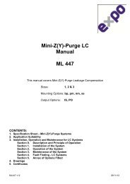
Mini-X-Purge Size 1 Manual ML 442 - Expo Technologies
Mini-X-Purge Size 1 Manual ML 442 - Expo Technologies
Mini-X-Purge Size 1 Manual ML 442 - Expo Technologies

Create successful ePaper yourself
Turn your PDF publications into a flip-book with our unique Google optimized e-Paper software.
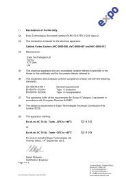
CERTIFICATION<br />
CERTIFICATION<br />
SCHEDULE<br />
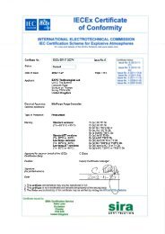
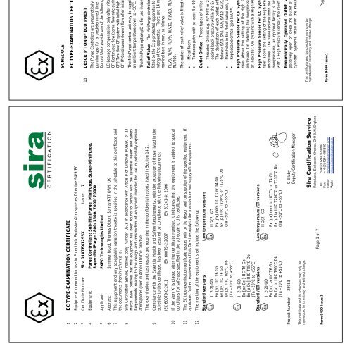
1 EC TYPE-EXAMINATION CERTIFICATE<br />
EC TYPE-EXAMINATION CERTIFICATE Sira 01ATEX1295X<br />
Issue 7<br />
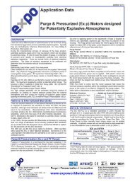
2 Equipment intended for use in Potentially Explosive Atmospheres Directive 94/9/EC<br />
13 DESCRIPTION OF EQUIPMENT<br />
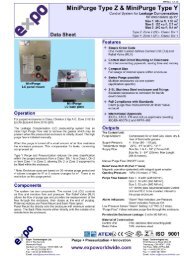
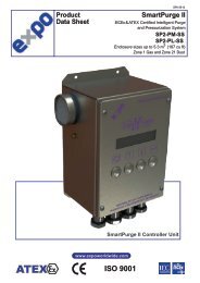
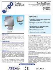
The <strong>Purge</strong> Controllers are pneumatically operated devices, which are intended to provide a given flow rate of<br />
purging gas for a predetermined time to unspecified Ex p protected electrical equipment. The <strong>Mini</strong><strong>Purge</strong><br />
Control Units provide one of the following four methods of purge operation.<br />
3 Certificate Number: Sira 01ATEX1295X Issue: 7<br />
4 Equipment: <strong>Purge</strong> Controllers: Sub-<strong>Mini</strong><strong>Purge</strong>, <strong>Mini</strong><strong>Purge</strong>, Super-<strong>Mini</strong><strong>Purge</strong>,<br />
Super-<strong>Mini</strong><strong>Purge</strong> 1800/3500/7000/7000X<br />
5 Applicant: EXPO <strong>Technologies</strong> Limited<br />
LC-Leakage compensation only after initial high purge<br />
CF-Continuous flow (same flow rate during and after purging)<br />
CF2-Two flow CF system with initial high purge rate only at one orifice<br />
CFHP-Continuous (lower) flow after initial high purge<br />
The <strong>Mini</strong><strong>Purge</strong> control unit may be supplied within a heated enclosure to permit the use of the system within<br />
an ambient temperature down to –50 o C.<br />
The <strong>Mini</strong><strong>Purge</strong> option pD is for use in combustible dust<br />
6 Address: Summer Road, Thames Ditton, Surrey KT7 ORH, UK<br />
7 This equipment and any acceptable variation thereto is specified in the schedule to this certificate and<br />
the documents therein referred to.<br />
8 Sira Certification Service, notified body number 0518 in accordance with Article 9 of Directive 94/9/EC of 23<br />
March 1994, certifies that this equipment has been found to comply with the Essential Health and Safety<br />
Requirements relating to the design and construction of equipment intended for use in potentially explosive<br />
atmospheres given in Annex II to the Directive.<br />
The examination and test results are recorded in the confidential reports listed in Section 14.2.<br />
Relief Valve - The <strong>Mini</strong><strong>Purge</strong> controller is supplied with an optional overpressure relief valve,whichistobe<br />
fitted to the Ex p protected apparatus to prevent an internal overpressure above the maximum overpressure<br />
rating of the apparatus. There are 14 models of relief valve; the designation of each relief valve refers to its<br />
nominal bore in mm, as follows:<br />
9 Compliance with the Essential Health and Safety Requirements, with the exception of those listed in the<br />
schedule to this certificate, has been assured by compliance with the following documents:<br />
IEC 60079-0:2011 EN 60079-2:2007 EN 61241-4: 2006<br />
RLV3, RLV6, RLV9, RLV12, RLV19, RLV25, RLV26, RLV52, RLV36, RLV75, RLV104, RLV125, RLV150 and<br />
RLV200.<br />
10 If the sign ‘X’ is placed after the certificate number, it indicates that the equipment is subject to special<br />
conditions for safe use specified in the schedule to this certificate.<br />
The outlet of each relief valve is fitted with a spark arrestor, of which there are four optional types:<br />
� Metal foam � Multi-layer stainless steel mesh<br />
� Tortuous path with at least 4 x 90�or 2 x 180� bends � Knitted mesh<br />
11 This EC type-examination certificate relates only to the design and construction of the specified equipment. If<br />
applicable, further requirements of this Directive apply to the manufacture and supply of this equipment.<br />
12 The marking of the equipment shall include the following:<br />
Outlet Orifice - Three types of orifice are used:<br />
� Threaded Orifices e.g. ¼� NPT or 2� BSP with a built in spark arrester. These are selected to maintain a<br />
desired back pressure within the Ex p protected apparatus when used with the Continuous Flow options.<br />
Thedesignationofeachoutletorificeindicatesthenominalinletdiameter. Thedesignationsareas<br />
follows: SA3, SA6, SA9, SA12, SA19, SA25, SA32, SA38 and SA50.<br />
� Plain holes in the Relief Valve disk, sizedaccordingtotheflow rate required.<br />
� Replaceable orifice type SAU**.<br />
Standard versions Low temperature versions<br />
II 2(2) GD II 2(2) GD<br />
Ex [px] IIC T6 Gb Ex [px] dem IIC T3 or T4 Gb<br />
Ex [py] IIC T6 Gb Ex [p] IIIC T200°C or T135°C Db<br />
Ex [p] IIIC T85°C Db (Ta –50°C to +55°C)<br />
(Ta –20°C to +55°C)<br />
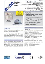
High Pressure Sensor for CF Systems (HP code) - If the pressure in the pressurized enclosure<br />
rises above the setting of the High Pressure sensor, the controller resets cutting the power to the<br />
enclosure. On detecting the overpressure an optional facility is available for the generation of an alarm<br />
or indicator. On systems with a High Pressure sensor, the relief valve may be omitted.<br />
II 2(3) GD<br />
Ex [pz Gc ] IIC T6 Gb<br />
Ex [p Dc] IIIC T85°C Db<br />
(Ta –20°C to +55°C)<br />
Standard /ET versions Low temperature /ET versions<br />
High Pressure Sensor for LC Systems (HP code) - If the pressure in the pressurized enclosure<br />
rises above the setting of the High Pressure sensor, the purge gas flow is isolated from the pressurised<br />
enclosure. The valve isolates both the leakage compensation and the purge streams. On detecting the<br />
overpressure, an optional facility isavailableforthegenerationofanalarm or indicator. On systems<br />
with a High Pressure sensor, the relief valve may be omitted.<br />
II 2(2) GD<br />
II 2(2) GD<br />
Ex [px] ia IIC T6 Gb Ex [px] dem ia IIC T3 or T4 Gb<br />
Ex [p] ia IIIC T95°C Db Ex [p] ia IIIC T200°C or T135°C Db<br />
(Ta –20 o Cto+55 o C) (Ta –50°C to +55°C)<br />
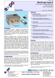
Pneumatically Operated Outlet Valve - The pneumatically operated outlet valve is used to<br />
positively open or close the outlet of the purged enclosure by means of a spring return pneumatic<br />
cylinder. Systems fitted with the Pneumatically Operated Outlet Valve will carry the option OV.<br />
Project Number 25983 C Ellaby<br />
Deputy Certification Manager<br />
This certificate and its schedules may only be<br />
reproduced in its entirety and without change.<br />
Sira Certification Service<br />
Rake Lane, Eccleston, Chester, CH4 9JN, England<br />
This certificate and its schedules may only be<br />
reproduced in its entirety and without change.<br />
Sira Certification Service<br />
Rake Lane, Eccleston, Chester, CH4 9JN, England<br />
Page 1 of 7<br />
Tel: +44 (0) 1244 670900<br />
Fax: +44 (0) 1244 681330<br />
Email: info@siracertification.com<br />
Web: www.siracertification.com<br />
Page 2 of 7<br />
Tel: +44 (0) 1244 670900<br />
Fax: +44 (0) 1244 681330<br />
Email: info@siracertification.com<br />
Web: www.siracertification.com<br />
Form 9400 Issue 1<br />
Form 9400 Issue1