Mini-X-Purge Size 1 Manual ML 442 - Expo Technologies
Mini-X-Purge Size 1 Manual ML 442 - Expo Technologies
Mini-X-Purge Size 1 Manual ML 442 - Expo Technologies

You also want an ePaper? Increase the reach of your titles
YUMPU automatically turns print PDFs into web optimized ePapers that Google loves.
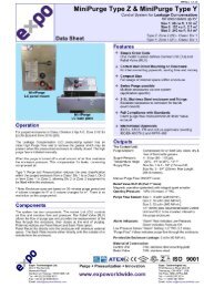
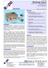
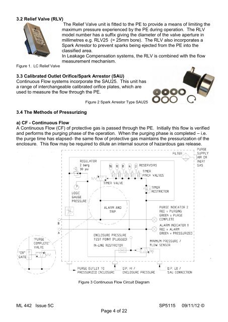
3.2 Relief Valve (RLV)<br />
The Relief Valve unit is fitted to the PE to provide a means of limiting the<br />
maximum pressure experienced by the PE during operation. The RLV<br />
model number has a suffix giving the diameter of the valve aperture in<br />
millimetres e.g. RLV25 (= 25mm bore). The RLV also incorporates a<br />
Spark Arrestor to prevent sparks being ejected from the PE into the<br />
classified area.<br />
In Leakage Compensation systems, the RLV is combined with the flow<br />
measurement mechanism.<br />
Figure 1. LC Relief Valve<br />
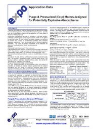
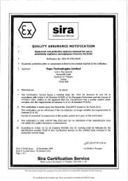
3.3 Calibrated Outlet Orifice/Spark Arrestor (SAU)<br />
Continuous Flow systems incorporate the SAU25. This unit has<br />
a range of interchangeable calibrated orifice plates, which are<br />
used to measure the flow through the PE.<br />
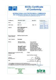
3.4 The Methods of Pressurizing<br />
Figure 2 Spark Arrestor Type SAU25<br />
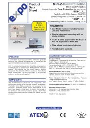
a) CF - Continuous Flow<br />
A Continuous Flow (CF) of protective gas is passed through the PE. Initially this flow is verified<br />
and performs the purging phase of the operation. When the purging phase is completed – i.e.<br />
the purge time has elapsed- the same flow of protective gas maintains the pressurization of the<br />
enclosure. This flow may be required to dilute an internal source of hazardous gas release.<br />
Figure 3 Continuous Flow Circuit Diagram<br />
<strong>ML</strong> <strong>442</strong> Issue 5C SP5115 09/11/12 ©<br />
Page 4 of 22