Mini-X-Purge Size 1 Manual ML 442 - Expo Technologies
Mini-X-Purge Size 1 Manual ML 442 - Expo Technologies
Mini-X-Purge Size 1 Manual ML 442 - Expo Technologies

You also want an ePaper? Increase the reach of your titles
YUMPU automatically turns print PDFs into web optimized ePapers that Google loves.
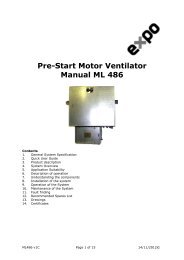
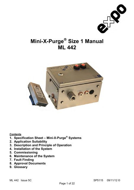
<strong>Mini</strong>-X-<strong>Purge</strong> � <strong>Size</strong> 1 <strong>Manual</strong><br />
<strong>ML</strong> <strong>442</strong><br />
Contents<br />
1. Specification Sheet – <strong>Mini</strong>-X-<strong>Purge</strong> � Systems<br />
2. Application Suitability<br />
3. Description and Principle of Operation<br />
4. Installation of the System<br />
5. Commissioning<br />
6. Maintenance of the System<br />
7. Fault Finding<br />
8. Approval Documents<br />
9. Glossary<br />
<strong>ML</strong> <strong>442</strong> Issue 5C SP5115 09/11/12 ©<br />
Page 1 of 22
1. Specification Sheet – <strong>Mini</strong>-X-<strong>Purge</strong> � Systems<br />
Model No. (Example): 07 1 XLC / ss / PO / WM (Note: Not all codes are applicable)<br />
<strong>Purge</strong> System Type<br />
07 = <strong>Mini</strong><strong>Purge</strong><br />
<strong>Size</strong><br />
1 = Sub <strong>Mini</strong><strong>Purge</strong><br />
<strong>Purge</strong> flow rate 225 Nl /min, 8 scfm<br />
Approval / Certification<br />
X =<br />
Europe<br />
EN60079-0, EN60079-2, EN 61241-0, EN61241-4<br />
Sira 01ATEX1295X<br />
0518 II 2 (2) G D<br />
Ex [px] IIC T6 Gb<br />
Ex [p] IIIC T85ºC Db<br />
Tamb -20ºC +55ºC<br />
IEC<br />
IEC60079-0, IEC60079-2, IEC61241-0, IEC61241-4<br />
IECEx SIR 07.0027X<br />
Ex [px] IIC T6 Gb<br />
Ex [p] IIIC T85ºC Db<br />
Tamb -20ºC +55ºC<br />
USA / Canada NFPA 496<br />
FM 1X8A4AE<br />
Class I Div 1 Groups A, B, C & D<br />
UL E190061<br />
Class I Div 1 Groups A, B, C & D<br />
BRAZIL INMETRO/TUV TÜV 12.1462X<br />
Ex [px] IIC T6 Gb<br />
Ex [p] IIIC T85ºC Db<br />
-20ºC ≤ Ta ≤ +55ºC<br />
For limitations and conditions of use refer to the<br />
applicable certificate at the back of this manual.<br />
Options as Required<br />
AO = Alarm Only<br />
MO = <strong>Manual</strong> Override<br />
MK = MIU Mounting Kit (PO systems only)<br />
WM = Wall Mounting Bars<br />
Power & Alarm (Signals)<br />
PO = Pneumatic Output<br />
“Power” : On <strong>Purge</strong> Complete = 30 psi / 0.2 MPa / 2 bar Signal<br />
“Alarm” : Loss of Pressure = No signal<br />
”Pressurized” = 30 psi / 0.2 MPa / 2 bar Signal<br />
PA = Power and Alarm Terminal Box Ex e IIC T6<br />
“Power” ; 250 Vac 4 Amp AC15 2PNO – Ex d IIC T6<br />
“Alarm” : 250 Vac 4 Amp AC15 SPCO – Ex d IIC T6<br />
(European and IEC Systems Only)<br />
IS = Intrinsically Safe, Ex i & Ex i circuit<br />
“Power” : used with others’ Ex i equipment<br />
“Alarm” : Relay / Barrier<br />
<strong>Mini</strong><strong>Purge</strong> � Housing<br />
ss = 316L Stainless Steel<br />
Neoprene “Top” Mount Gasket<br />
pm = Panel Mount (Side/Front Mount) 316L<br />
Stainless Steel<br />
Presurization Method<br />
CF = Continuous Flow<br />
LC = Leakage Compensation<br />
Supply Pressure: Must be regulated at inlet<br />
<strong>Mini</strong>mum 60 psi / 0.4 MPa / 4 bar<br />
Maximum 115 psi / 0.8 MPa / 8 bar<br />
Air Quality: Compressed air / Nitrogen to instrument quality<br />
Ambient Temperature: -20ºC to + 55ºC<br />
Leakage Compensation: Variable up to 2 scfm / 60 Nl/min to compensate for leakage of enclosure<br />
<strong>Purge</strong> Timer: Stepped adjustable between 1 minute and 30 minutes<br />
Flow & Pressure Sensors: CF: One sensor for both<br />
“Low Pressure and Flow”: 1” WC / 250 Pa (2.5 mbar)<br />
LC: “Low Pressure Sensor” 0.2” WC / 50 Pa (0.5 mbar)<br />
“Flow Sensor” 1.13” WC/ 280 Pa / (2.8 mbar)<br />
Relief Valve: System: CF LC<br />
Model No: RLV25/ss RLV25/FS/ss<br />
Opening Pressure: 4” WC / 1 kPa (10 mbar) 4” WC / 1 kPa (10 mbar)<br />
<strong>Purge</strong> Flow Rate: N/A (see Spark Arrestor) 8 scfm / 225 Nl/min<br />
Material: 316L Stainless Steel, Spark Arrestor: Stainless Steel mesh, Gasket: Neoprene<br />
Spark Arrestor Unit Model No: SAU25<br />
(CF systems only) <strong>Purge</strong> / Dilution Flow Rate: Between 0.4 & 8 scfm / 10 & 225 Nl/min<br />
7 user selectable orifice plates<br />
Material: Stainless Steal<br />
Bulkhead Pipe Fittings: Air Supply: 1/2” NPT<br />
Output: 1/2” NPT<br />
Signal: 1/8” NPT<br />
Visual Indicators: CF: Alarm / Pressurized (Red / Green)<br />
<strong>Purge</strong> Complete (Red / Green)<br />
LC: Alarm / Pressurized (Red / Green)<br />
<strong>Purge</strong> Complete (Black / Amber)<br />
Action on “Loss of Pressure”:<br />
CF: Action on “Loss of Pressure” = “Alarm & Trip”. Option /AO specifies an “Alarm Only” kit.<br />
LC: Action on “Loss of Pressure” = “Alarm & Trip” or “Alarm Only”. LC Model is user selectable.<br />
<strong>ML</strong> <strong>442</strong> Issue 5C SP5115 09/11/12 ©<br />
Page 2 of 22
2. Application Suitability<br />
<strong>Mini</strong><strong>Purge</strong> � Systems are certified for use in Hazardous Areas, where the Hazardous Area is<br />
non-mining (i.e. above ground) and the hazard is caused by flammable gasses, vapours or dust.<br />
Depending on the model, the systems may be used in IECEx, ATEX Zone 1(21) - Category 2<br />
and NEC 500 Class I, Div 1.<br />
<strong>Mini</strong><strong>Purge</strong> � systems may be used for hazards of any gas group. However, apparatus<br />
associated with the <strong>Mini</strong><strong>Purge</strong> � system, such as Intrinsically Safe signalling circuits and<br />
flameproof enclosures containing switching devices may be limited in their gas group. The<br />
certification documentation supplied with any such devices must be checked to ensure their<br />
suitability.<br />
This system is designed for use primarily with compressed air. Where other inert compressed<br />
gasses are used (Nitrogen, for example) the user must take suitable precautions so that the<br />
build up of the inert gas does not present a hazard to health. Consult the Control of Substances<br />
Hazardous to Health (COSHH) data sheet for the gas used. Where a risk of asphyxiation<br />
exists, a warning label must be fitted to the Pressurized Enclosure.<br />
The following materials are used in the construction of <strong>Mini</strong><strong>Purge</strong> � systems. If substances that<br />
will adversely affect any of these materials are present in the surrounding environment, please<br />
consult <strong>Expo</strong> for further guidance.<br />
Materials of construction:<br />
� Stainless Steel � Aluminium � Acrylic<br />
� Mild (carbon) Steel � Nylon � Silicone Rubber<br />
� Brass � Polyurethane � Neoprene<br />
3. Description and Principle of Operation<br />
All <strong>Expo</strong> <strong>Technologies</strong> <strong>Mini</strong><strong>Purge</strong> � pressurization systems provide:<br />
a) a method of pressurizing a Pressurized Enclosure (PE) while at the same time compensating<br />
for any leakage, together with<br />
b) a method of purging the enclosure, before power is applied, to remove any flammable gas<br />
that may have entered the enclosure while it was not pressurized,<br />
c) visual indication of the <strong>Mini</strong><strong>Purge</strong> � system status, and<br />
d) an output to provide remote indication or control.<br />
The <strong>Mini</strong><strong>Purge</strong> � system comprises a number of component units. The units required depend on<br />
the type of system selected. These are summarised in Table 1. The general description and<br />
function of each is as follows:<br />
3.1 Control Unit (CU)<br />
The Control Unit (CU) is the heart of the system. It contains a pneumatic logic circuit specially<br />
designed and built to control the functions required for purge and pressurization. For all<br />
systems this includes air filtration, pressure and purge flow measurement, purge timing, and<br />
local visual indication of Pressurized/Alarm and flow sensed. It also provides the outputs for<br />
power and remote alarm control corresponding to the output type selected.<br />
<strong>ML</strong> <strong>442</strong> Issue 5C SP5115 09/11/12 ©<br />
Page 3 of 22
3.2 Relief Valve (RLV)<br />
The Relief Valve unit is fitted to the PE to provide a means of limiting the<br />
maximum pressure experienced by the PE during operation. The RLV<br />
model number has a suffix giving the diameter of the valve aperture in<br />
millimetres e.g. RLV25 (= 25mm bore). The RLV also incorporates a<br />
Spark Arrestor to prevent sparks being ejected from the PE into the<br />
classified area.<br />
In Leakage Compensation systems, the RLV is combined with the flow<br />
measurement mechanism.<br />
Figure 1. LC Relief Valve<br />
3.3 Calibrated Outlet Orifice/Spark Arrestor (SAU)<br />
Continuous Flow systems incorporate the SAU25. This unit has<br />
a range of interchangeable calibrated orifice plates, which are<br />
used to measure the flow through the PE.<br />
3.4 The Methods of Pressurizing<br />
Figure 2 Spark Arrestor Type SAU25<br />
a) CF - Continuous Flow<br />
A Continuous Flow (CF) of protective gas is passed through the PE. Initially this flow is verified<br />
and performs the purging phase of the operation. When the purging phase is completed – i.e.<br />
the purge time has elapsed- the same flow of protective gas maintains the pressurization of the<br />
enclosure. This flow may be required to dilute an internal source of hazardous gas release.<br />
Figure 3 Continuous Flow Circuit Diagram<br />
<strong>ML</strong> <strong>442</strong> Issue 5C SP5115 09/11/12 ©<br />
Page 4 of 22
) LC - Leakage Compensation<br />
Initially a high flow of protective gas is passed through the enclosure. This flow is verified and<br />
performs the purging phase of the operation. When the purging phase is completed – i.e. the<br />
purge time has elapsed - the flow of protective gas is provided via an adjustable valve so that it<br />
just compensates for any leakage from the PE in addition to maintaining its pressurization.<br />
If leakage is less than 5 l/min then the LCV will be awkward to set. You will find that the RLV<br />
spring will cycle open and closed. If this happens contact our service department for advice.<br />
Figure 4 Leakage Compensation Circuit Diagram<br />
3.5 Type of Output<br />
The functions of the outputs are power control and alarm/pressurized indication. Power control<br />
provides a signal to switch the power to the PE. Alarm output provides a passive signal to<br />
indicate remotely when the enclosure is not pressurized and an active signal when pressurized.<br />
a) PO- Pneumatic Output<br />
The power control and pressurized outputs are pneumatic signals, which may be used to<br />
operate other devices to provide power switching or alarm indication. The lack of any output<br />
signal indicates incomplete purge and alarm. In many instances these outputs may be<br />
connected to the <strong>Expo</strong> range of <strong>Mini</strong><strong>Purge</strong> � Interface Unit s (MIU).<br />
Figure 6 Pneumatic Output Option<br />
Figure 5 Typical <strong>Mini</strong><strong>Purge</strong> Interface Unit<br />
type (MIU/dA)<br />
<strong>ML</strong> <strong>442</strong> Issue 5C SP5115 09/11/12 ©<br />
Page 5 of 22
) IS - Intrinsically Safe Output<br />
The power control and alarm outputs are volt free contacts which form part of an Intrinsically<br />
Safe (IS) circuit which then provides power control or alarm outputs in a safe (unclassified)<br />
area. These contacts must only be connected to IS circuits as the switch contacts are in the<br />
hazardous area. In many instances these outputs may be connected to the <strong>Expo</strong> range of<br />
<strong>Mini</strong><strong>Purge</strong> � Interface Units (MIU).<br />
Figure 7. Intrinsically Safe (IS) Option<br />
c) PA - Power and Alarm<br />
By integral Ex d flameproof switches, terminated in Ex e junction box in accordance with<br />
European standards.<br />
Figure 8. Ex de Power and Alarm (PA) Option<br />
<strong>ML</strong> <strong>442</strong> Issue 5C SP5115 09/11/12 ©<br />
Page 6 of 22
4. Installation of the System<br />
This <strong>Mini</strong><strong>Purge</strong> � is designed for use under normal industrial conditions of ambient temperature,<br />
humidity and vibration. Please consult <strong>Expo</strong> before installing this equipment in conditions that<br />
may cause stresses beyond normal industrial conditions.<br />
The <strong>Mini</strong><strong>Purge</strong> � system shall be installed in accordance with relevant standards, such as IEC /<br />
EN 60079-14, NEC 500, NFPA 496 and any local codes of practice that are in force.<br />
There are up to three components for the <strong>Mini</strong><strong>Purge</strong> � system, dependant upon the system type:<br />
System type Control Unit (CU)<br />
Relief Valve<br />
(RLV)<br />
Spark Arrestor<br />
Unit<br />
Leakage Compensation YES YES Integral to RLV<br />
Continuous Flow YES YES YES (SAU25)<br />
Table 1 System Components<br />
4.1 Control Unit (CU)<br />
The <strong>Mini</strong><strong>Purge</strong> � system should be installed either directly on or close to the PE. See mounting<br />
details. Generally the most convenient arrangement is to install the CU on the top of the PE.<br />
Must be mounted vertically as shown in <strong>Mini</strong><strong>Purge</strong> � Configuration XBR-7TD0-003. The CU can<br />
be mounted on the side of the PE using the rear mounting fixings. The piped connections to the<br />
PE should be made using metallic tube through suitable bulkhead connections. The CU can be<br />
remote mounted using the wall mounting bars (/WM option), and should be installed as close as<br />
possible to the PE. It should be installed so that the system indicators and certification labels<br />
may be readily observed.<br />
4.2 Relief Valve (RLV) and Spark Arrestor Unit (SAU)<br />
To achieve efficient purging the points where air enters and exits the PE should normally be at<br />
opposite ends of the PE. These items must be mounted vertically. The RLV or SAU are<br />
recommended to be situated at the bottom, or on the side of the enclosure at the bottom, when<br />
the CU is top mounted on the enclosure, thus achieving top to bottom purging. The purge air<br />
may be piped within the PE to ensure purging of potential dead air spots.<br />
It is important that the interior and exterior of the Spark Arrestor is kept clean and debris is not<br />
allowed to accumulate which might affect the calibration of the device. In particular the exterior<br />
of the Spark Arrestor should not be painted or blocked off in any way.<br />
4.3 Connections to Protective Gas Supply<br />
The <strong>Mini</strong><strong>Purge</strong>� system should be connected to a protective gas supply, which is suitable for<br />
purging and pressurization. The air supply to the filtration system must be clean, nonflammable,<br />
from a non-hazardous area and free from water and oil to BS ISO 8573-1: 2001<br />
Class 2.2.1 or relevant local standards. This is typically referred to as “Instrument Air Quality”.<br />
Solid Particles: 0.5µm < particle size � 1µm, maximum 1000 particles/m3<br />
Humidity: -40ºC* pressure dewpoint<br />
Oil content: �0.01mg/m3 concentration total oil<br />
* For applications where Tamb � 0ºC, the air supply should be Class 2.1.1, with Humidity: -70ºC<br />
pressure dewpoint.<br />
Although equipment will operate with lower air quality, the operational life of the system will be<br />
adversely affected. The equipment that is being protected may also suffer from poor air quality.<br />
<strong>ML</strong> <strong>442</strong> Issue 5C SP5115 09/11/12 ©<br />
Page 7 of 22
The minimum air supply pressure should be 4 bar/ 60 psig / 4MPa. It is important that the<br />
compressed air / inert gas supply is capable of delivering the quantity required for purging at<br />
normal purge flow rate, maintaining the minimum pressure. This means ensuring adequate size<br />
of pipe and airline accessories. Over 80% of commissioning problems reported to <strong>Expo</strong> are due<br />
to inadequate sized piping or air supply. Although the <strong>Mini</strong><strong>Purge</strong> � unit includes a filter, the<br />
compressed air / inert gas supply should have a dedicated local air pressure regulator.<br />
4.4 <strong>Purge</strong> Air from CU to PE<br />
When the CU is directly top mounted onto the PE, no connection will normally be necessary, as<br />
the purge air will discharge into the PE directly. When the CU is not top mounted, or where<br />
internal air distribution is necessary a connection should be made from the purge air outlet on<br />
the CU (normally ½” NPT Female), via pipe pressure rated at least to the supply pressure, to<br />
the PE. This should be kept as short as possible and should be adequately sized to ensure that<br />
the full purge flow can be delivered.<br />
4.5 CU to Enclosure Pressure Monitor<br />
When the CU is directly top mounted onto the PE, no connection will normally be necessary, as<br />
the enclosure pressure monitor point will sense directly inside the PE. Only if the CU is not<br />
directly mounted or if there are fans, which may create localised low-pressure areas within the<br />
PE, it is necessary to pipe this connection. The connection is made to the enclosure pressure<br />
sensor fitting (normally 1/8” NPT Female) on the CU. There is virtually no flow in this circuit, so<br />
small bore tube may be used. <strong>Expo</strong> recommends 4mm O/D nylon tube. Make sure that all<br />
connections are free of leaks.<br />
4.6 CU to Flow Sensor<br />
In Continuous Flow (CF) systems, a Differential Pressure Sensor is combined with the <strong>Mini</strong>mum<br />
Pressure Sensor and measures the "DP HI (High) / Enclosure Pressure" within the PE and the<br />
pressure in the monitoring device at the back of the SAU "DP LO (Low) SAU Connection". This<br />
connection requires a pipe connection between the CU and the SAU25.<br />
In Leakage Compensation (LC) systems a dedicated <strong>Purge</strong> Flow Sensor measures the<br />
differential pressure between the "DP HI (High) / Enclosure Pressure" and the pressure in the<br />
monitoring device at the back of the RLV "DP LO (Low) RLV Connection". This connection<br />
requires a pipe to connect the CU to the RLV25.<br />
4.7 Power Supplies and their Isolation<br />
All power entering the PE shall be provided with a means of isolation. This requirement also<br />
applies to any external power sources, which are connected to equipment such as "volt-free" or<br />
"dry" contacts within the PE. Printer signal, network cards, etc need isolation.<br />
Exception: Power to other apparatus that is already suitable for the hazardous area need not to<br />
be isolated by the <strong>Mini</strong><strong>Purge</strong>� system.<br />
In all cases the application and the isolation of the power must be controlled by the <strong>Mini</strong><strong>Purge</strong> �<br />
system. Refer to Specification Sheet for output options available.<br />
4.8 Adjustments and Settings<br />
<strong>Purge</strong> Time<br />
If no specific purge test has been performed on the PE, the volume of the PE must be<br />
determined by the manufacturer or user and the necessary purging time calculated based on<br />
the purge flow rate specified by the “standard” being used. It is the user's responsibility to verify<br />
or enter this data on the PE and/or <strong>Mini</strong><strong>Purge</strong> � system nameplate. Ask <strong>Expo</strong> if in doubt. The<br />
IEC / EN 60079-2 permits 5 free volume changes and an example of the calculations is as<br />
follows:<br />
<strong>ML</strong> <strong>442</strong> Issue 5C SP5115 09/11/12 ©<br />
Page 8 of 22
If the PE external dimensions indicate an internal free volume of 500 Litres then,<br />
500 litres enclosure volume x 5 volume changes = 12 minutes purge time<br />
225 litres/minute purge flow rate<br />
If the PE is a motor, experience of purge testing shows that it is prudent to multiply the<br />
motor internal "free” volume by ten to get the purging volume.<br />
500 litres enclosure volume x 10 volume changes = 23 minutes purge time<br />
225 litres/minute purge flow rate<br />
The following applies for NFPA 496 standards where 4 complete volume changes are permitted<br />
for enclosures except when the PE contains a motor when 10 volume changes are required.<br />
If the PE external dimensions indicate a total volume of 8 cubic foot, then,<br />
8 cubic foot enclosure volume x 4 volume changes = 4 minutes purge time<br />
8 cubic foot/minute purge flow rate, (see above)<br />
If the same PE contains a motor, then,<br />
8 cubic foot enclosure volume x 10 volume changes = 10 minutes purge time<br />
8 cubic foot/minute purge flow rate, (see above)<br />
Figure 9 <strong>Mini</strong><strong>Purge</strong> � timer block<br />
The standard <strong>Mini</strong><strong>Purge</strong> � units have the patented digital<br />
pneumatic timer system as shown in Figure 9<br />
<strong>Mini</strong><strong>Purge</strong>� timer block. The purge time is set by<br />
opening / closing the pinch valve so that the sum of the<br />
open valve times equals or exceeds the required purge<br />
time. At least one valve must always be open, and<br />
the screws must be at the appropriate limit of travel.<br />
Do not over tighten.<br />
<strong>Purge</strong> Flow Rate (Orifice <strong>Size</strong> Selection) – Only for CF Systems<br />
The purge flow rate is selected by placing the appropriate orifice plate in the SAU. The purge<br />
flow rates given in Table 2 are based on standard setting of the flow sensor of 2.5mbar, 1” WC,<br />
250Pa. For LC systems the purge flow rate is set by the selection of the RLV and is not user<br />
adjustable.<br />
Continuous Flow Rate with<br />
2.5 mbarg, 1” WC, 250 Pa<br />
flow sensor set point<br />
N litre/minute SCFM<br />
A 10 0.4<br />
B 25 0.9<br />
C 40 1.4<br />
D 65 2.3<br />
E 90 3.2<br />
F 135 4.8<br />
G 180 6.4<br />
Orifice Plate<br />
Number<br />
NO ORIFICE 225 8.0<br />
Table 2 <strong>Purge</strong> Flow Rates<br />
<strong>ML</strong> <strong>442</strong> Issue 5C SP5115 09/11/12 ©<br />
Page 9 of 22
Action on Loss of Pressurization<br />
The action on loss of pressurization is the responsibility of the user.<br />
The action on loss of pressurization can be set to ALARMS ONLY (AO), or ALARM AND<br />
AUTOMATIC DISCONNECT OF POWER (A&T).<br />
a) Leakage Compensation<br />
The action on loss of pressurization is set by moving the<br />
jumper tube (see Figure 10 Action on Loss of<br />
Pressurization Jumper Tube). The standard setting is<br />
Alarm and Trip where the link is from C to A&T, with a<br />
plug in AO. Changing to Alarm Only (AO) is user<br />
adjustable by moving the link from C to AO, and plugging<br />
A&T.<br />
Figure 10 Action on loss of pressurization jumper tube<br />
b) Continuous Flow<br />
The standard CF system is built set to Alarm and Trip. Alarm Only can be installed when order<br />
specified or supplied as a retrofit kit later. See options.<br />
The selection for action on loss of pressurization depends on the area of operation and the<br />
following guidelines should be followed.<br />
The user must make use of this alarm facility in accordance with the local code of practice for<br />
"action on pressure or flow failure". Most codes include the following recommendations:<br />
Zone 1 Installations:<br />
Alarm and automatic disconnect of power.<br />
Exception: If the equipment inside the PE is suitable for use in Zone 2, the power trip may be<br />
performed manually, (no automatic power trip), if the pressure or flow failure persists for an<br />
unacceptable time.<br />
Zone 2 Installations:<br />
Alarm Only on pressure or flow failure with power being removed manually by turning off the air<br />
supply to the <strong>Mini</strong><strong>Purge</strong> � system if the failure persists for an unacceptable time.<br />
Class I Division 1 Installations:<br />
Alarm and Automatic Trip of Power. Note: NFPA 496 states power to the circuits shall be<br />
permitted to be continued for a short period if immediate loss of power would result in a more<br />
hazardous condition and if both audible and visual alarms are provided at a constantly attended<br />
location.<br />
Class I Division 2 Installations:<br />
Where automatic timing is preferred, Alarm Only on pressure or flow failure with power being<br />
removed manually by turning off the air supply to the <strong>Mini</strong><strong>Purge</strong> � system if the failure persists<br />
for an unacceptable time.<br />
4.9 Internal Gas Release<br />
If the PE contains an internal source of release of flammable gas or vapour, the procedures for<br />
assessment of the release as given in NFPA 496 or IEC / EN 60079-2 should be used. <strong>Expo</strong> is<br />
pleased to provide assistance or consultancy and advice on such matters.<br />
The user must verify that the specifications of the <strong>Expo</strong> system e.g. pressure, continuous flow<br />
(dilution) rate and type of protective gas are correct for the specific application.<br />
<strong>ML</strong> <strong>442</strong> Issue 5C SP5115 09/11/12 ©<br />
Page 10 of 22
4.10 Multiple Enclosures<br />
More than one PE can be protected by a single system. Where PEs are connected and purged<br />
in "series" e.g. "Daisy Chained", the RLV and when using a CF system, the SAU25 should be<br />
fitted on the last enclosure with the <strong>Purge</strong> Inlet connected to the first enclosure. The bore and<br />
length of the pipe or conduit used to interconnect the enclosures is critical and will determine<br />
the maximum pressure experienced by the first enclosure in the series. Advice on sizing can be<br />
obtained from the <strong>Expo</strong> sales office but in general terms when using RLV25 or SAU25, the pipe<br />
bore size should not be less than 25mm (1”).<br />
A common fault of installing small bore pipe leads to over pressurizing of all but the last<br />
enclosure.<br />
PEs should not be connected in parallel.<br />
5. Commissioning<br />
Start by check that the system has been installed in<br />
accordance with this manual.<br />
Disconnect the supply pipe from the inlet to the <strong>Mini</strong><strong>Purge</strong> �<br />
system and blow it through for at least 10 seconds per meter<br />
(3ft) of length to remove any debris or condensation.<br />
Connect a temporary pressure gauge or water manometer to<br />
the PE or <strong>Mini</strong><strong>Purge</strong> � system pressure test point (Remove the<br />
red plug on the low pressure sensor and connect 4mm OD<br />
nylon tube).<br />
Figure 11. PE or <strong>Mini</strong><strong>Purge</strong> � system pressure test point<br />
Unless a supply shut-off valve has been specially fitted inside the <strong>Mini</strong><strong>Purge</strong> � system, it may be<br />
advisable to install an external shutoff valve with the same, or larger, thread size as the<br />
<strong>Mini</strong><strong>Purge</strong> � CU inlet fitting upstream of the connection.<br />
5.1 Continuous Flow (CF) Systems<br />
Open the Flow Control Valve (FCV) until the alarm/pressurized indicator just turns from red to<br />
green. Clockwise will reduce the flow and anti-clockwise will increase the airflow.<br />
If the FCV is opened fully and the indicator has still not turned green, check the air supply<br />
pressure at the inlet to the control unit while flow is taking place. It must be above the<br />
minimum 4 bar/ 60 psig/ 400kPa specified.<br />
Figure 12. Flow Control Valve (FCV)<br />
Check that the internal logic gauge reads 2bar /30 psig/200kPa.<br />
The purge timer will start as soon as the ‘alarm/pressurized’<br />
indicator turns from red (alarm) to green (pressurized). Check that<br />
the time delay between the indicator turning green and the<br />
application of power to the PE is not less than the minimum time<br />
required to purge the PE. When the purge time has been<br />
completed, the ‘purge complete’ indicator will turn from red to<br />
green.<br />
After the power has been turned on by the CU, the air flow will<br />
continue at the same rate to provide dilution as required.<br />
<strong>ML</strong> <strong>442</strong> Issue 5C SP5115 09/11/12 ©<br />
Page 11 of 22
5.2 Leakage Compensation Systems (LC)<br />
Figure 13 Leakage Compensation Valve<br />
Open the Leakage Compensation Valve (LCV) fully, turn anti-clockwise.<br />
Clockwise will reduce the flow and anti-clockwise will increase the airflow.<br />
Open the supply regulator SLOWLY and allow the PE pressure to rise until<br />
the RLV opens. Check that the RLV opens at or below the figure specified<br />
in the documentation.<br />
Note tolerance of � 2 mbarg / 0.8” WC / 200Pa<br />
Repeat the test several times.<br />
Open the supply regulator to between 4 and 8 barg / 60 and 115 psi / 400<br />
and 800 kPa and the purging flow will start.<br />
Check that the internal logic gauge reads 2 bar /30 psi / 200 kPa<br />
At this time the "alarm/pressurized” indicator should be green and the "purging” indicator should<br />
be yellow. If the yellow indicator remains black the flow through the RLV is below the minimum<br />
for which the flow sensor has been calibrated. Check the air supply pressure at the inlet to<br />
the control unit while purging is taking place. It must be above the minimum specified.<br />
The purge timer will start as soon as the "purging" indicator turns yellow. Check that the time<br />
delay between the “purging” indicator turning yellow and the application of power to the PE is<br />
not less than the minimum time required purging the PE. Times in excess of the minimum are<br />
permitted and a tolerance of +20% is normally acceptable. If the time is too short it must be<br />
increased accordingly.<br />
After the power has been applied via the CU, the purging valve will close and the air flow into<br />
the enclosure will be controlled by the LCV. The initial setting of fully open will normally be too<br />
high. It should now be adjusted to set the PE pressure and leakage. There are three possible<br />
situations:<br />
Air continues to come out through the RLV Spark Arrestor after power has been applied in<br />
considerable quantity. The LCV is much too far open and the air flow is holding the RLV<br />
open continuously.<br />
Close the LCV slowly. The PE pressure will start to fall as the flow decreases but eventually<br />
the RLV will close and the enclosure pressure rise again. At this point the RLV may start to<br />
open intermittently as the PE pressure rises to the point where it exceeds the RLV opening<br />
pressure. When the RLV opens the pressure will fall quickly to the point where the RLV recloses<br />
and the enclosure pressure starts to rise again. This is entirely normal for this type of<br />
RLV.<br />
If the RLV is opening intermittently the LCV is slightly too far open. When the RLV opens<br />
the enclosure pressure falls quickly to the point where the RLV re-closes and the enclosure<br />
pressure starts to rise again. This is entirely normal for this type of RLV and shows that it is<br />
working correctly.<br />
Continue then to close the LCV until the cycling stops and the enclosure pressure starts to<br />
fall. Carefully adjust the LCV until the PE pressure is approximately 50% of the RLV<br />
opening pressure and stable. This pressure may be around 5 mbarg / 2” WC / 500 Pa and<br />
will be the "normal working pressure".<br />
We recommend that the setting of the minimum pressure sensor be checked at this time. Note<br />
the position of the LCV knob. (A pencil mark placed on the knob at "12 O'clock” can be used).<br />
Slowly lower the PE pressure by closing the LCV further, counting the number of turns from the<br />
"normal working pressure" position. Note the pressure at which the "alarm/pressurized"<br />
indicator turns from green to red and check that it is not lower than the figure given in the<br />
<strong>ML</strong> <strong>442</strong> Issue 5C SP5115 09/11/12 ©<br />
Page 12 of 22
documentation. Check also the "alarm" electrical contacts. As soon as the "alarm/pressurized"<br />
indicator turns red, the system will start to re-purge. If Alarm and Trip function is selected the<br />
enclosure power will be switched off.<br />
While it is re-purging return the LCV to its "normal working pressure" position so that, at the end<br />
of purging, the enclosure pressure should immediately settle down at the correct "normal"<br />
pressure.<br />
If, at the end of purging, the PE pressure falls below the minimum pressure sensor setting<br />
and the LCV is fully open, the system will start to purge again. This is indicative of<br />
excessive leakage from the enclosure. In this case, check the enclosure for leakage, and<br />
reduce or eliminate the leaks. This time, at the end of purging, the enclosure should stay<br />
pressurized and the RLV action is as in a) or b) above. Proceed as described above.<br />
5.3 Normal operation<br />
Turn the air supply on or off to start or stop the system. After this the pressurizing and purging<br />
sequence is entirely automatic<br />
6. Maintenance of the System<br />
The maintenance recommended for the system consists of the following items, supplemented<br />
by any additional local requirements imposed by the local Code of Practice. <strong>Expo</strong> recommends<br />
that the commissioning tests be repeated at least every six months.<br />
In addition the following checks are also recommended at that time:<br />
Check the RLV and all Spark Arrestors. Remove all debris & corrosion, or replace with a<br />
spare.<br />
Check the condition of the air supply filter element. Clean or replace it as necessary.<br />
At least every two years check the following additional items:<br />
Apparatus is suitable for the Hazardous Location<br />
There are no unauthorised modifications<br />
The air supply must be to the correct quality, refer to section Air Quality<br />
The interlocks and alarms function correctly<br />
Approval labels are legible and undamaged<br />
Adequate spares are carried<br />
The action on pressure failure is correct<br />
Pressure sensor calibration<br />
If it is decided that the minimum pressure /purge flow sensor needs recalibrating it must be<br />
returned to <strong>Expo</strong> for this service.<br />
Filter cleaning<br />
If the filter element needs cleaning the filter bowl can be unscrewed and removed. The filter<br />
element also unscrews and can then be cleaned in soapy water. Do not use solvents on any<br />
part of the filter assembly.<br />
<strong>ML</strong> <strong>442</strong> Issue 5C SP5115 09/11/12 ©<br />
Page 13 of 22
7. Fault Finding<br />
If the system does not behave in the manner described above there is a fault. Some of the<br />
more likely faults are dealt with below. If a cure cannot be affected by following the procedure<br />
shown below please call <strong>Expo</strong> (24 hour answering) or your supplier for further assistance.<br />
The system has been designed for ease of fault finding and the many of the components fitted<br />
are plug-in or manifold mounted. Check components by substitution only after establishing that<br />
such action is necessary. If the system is less than 12 months old, parts under warranty should<br />
be returned to <strong>Expo</strong> for investigation, with a full report of the fault and the system serial number.<br />
As with any pneumatic system the greatest enemies are water, oil and dirt in the air supply. For<br />
this reason the air system must always incorporate a dust and water filter. This can be part of<br />
the <strong>Expo</strong> system or can be provided by others. However dirt can enter from other sources and<br />
it is vital therefore that the procedures described in Section 2 is carried out before using the<br />
system for the first time, or following any disconnection of the pipe-work. Failure to perform this<br />
work may cause damage that will not be covered under warranty.<br />
Before making the following checks verify that both the main air supply pressure to the purge<br />
system & the regulated pressure to the logic are as specified on the system specification sheet.<br />
Different flow charts for faulting have been provided for both the CF and LC options.<br />
<strong>ML</strong> <strong>442</strong> Issue 5C SP5115 09/11/12 ©<br />
Page 14 of 22
Fault Finding (CF)<br />
Pressurized/Purging indicator<br />
will not turn green during<br />
start up<br />
Is the air supply<br />
pressure<br />
incorrect?<br />
No<br />
Is the supply<br />
pipe to the air<br />
inlet as least<br />
12mm I.D?<br />
Yes<br />
Is there<br />
excessive<br />
leakage from<br />
the PE?<br />
No<br />
Is the PE<br />
strong enough?<br />
Yes<br />
Is the Pressure /<br />
Flow Sensor out<br />
of calibration or<br />
faulty?<br />
No<br />
Call <strong>Expo</strong><br />
Yes<br />
Yes<br />
No<br />
Yes<br />
No<br />
Check the air<br />
supply pressure<br />
at the inlet to the<br />
<strong>Mini</strong><strong>Purge</strong> is<br />
stable between<br />
4 - 8 Barg /<br />
60 - 115 psi<br />
Replace pipe<br />
work<br />
Any significant<br />
leakage must be<br />
corrected. Check<br />
for leaks down<br />
the cables or<br />
conduit. Ensure<br />
leakage does not<br />
exceed 60 Nl/min<br />
(25 cfm)<br />
The standard<br />
requires that the<br />
PE is tested to<br />
1.5 times the<br />
Relief Valve<br />
opening pressure<br />
e.g. 15 mbarg for<br />
many systems.<br />
Has this been<br />
done?<br />
The basic operation of the Pressure Sensor<br />
can be checked by unscrewing the 60mm<br />
diameter diaphragm housing and, by using a<br />
rubber pad, e.g. an eraser, block the 12mm<br />
threaded hole in the top of the valve module.<br />
The valve should operate and the indicator<br />
turn green. If this is correct, the sensor<br />
diaphragm needs recalibrating or replacing.<br />
<strong>ML</strong> <strong>442</strong> Issue 5C SP5115 09/11/12 ©<br />
Page 15 of 22
System fails to switch power<br />
on after the purge time has<br />
elapsed.<br />
Is Power<br />
available?<br />
Yes<br />
Is Power<br />
isolator closed?<br />
Yes<br />
Are the fuses or<br />
circuit breaker?<br />
OK?<br />
Yes<br />
Has the purge<br />
time completed<br />
its course?<br />
Yes<br />
For PO option only<br />
Is there pressure at the<br />
power switch output<br />
bulkhead and at the<br />
power switch? Is the<br />
power switch OK?<br />
Yes<br />
For PO option only<br />
Is the tube to the<br />
power switch air<br />
tight?<br />
Yes<br />
Is the <strong>Purge</strong><br />
time correct?<br />
Yes<br />
Call <strong>Expo</strong><br />
No<br />
<strong>ML</strong> <strong>442</strong> Issue 5C SP5115 09/11/12 ©<br />
Page 16 of 22<br />
No<br />
No<br />
No<br />
No<br />
No<br />
No<br />
Check the small<br />
indicator button<br />
on the timer<br />
valve. When the<br />
valve has timed<br />
out, it should<br />
return out when<br />
depressed.<br />
Check if the<br />
external Power<br />
Switch contacts<br />
close at 1.4 Barg<br />
Ensure fitting nuts<br />
are tightened and<br />
that the tube is<br />
not damaged.<br />
Check and repair<br />
as necessary.<br />
Note the timer setting. Reset the timer to the<br />
minimum available purging period and check<br />
the operation on that purge time.<br />
Ensure that the purge time is returned to<br />
its original setting and checked before<br />
putting the system back into service.
Relief Valve opens<br />
continuously or<br />
intermittently.<br />
Is the Pressurized<br />
Enclosure<br />
pressure too<br />
high?<br />
No<br />
Is there debris on<br />
the RLV disk<br />
allowing air to<br />
leak from the<br />
valve?<br />
No<br />
Call <strong>Expo</strong><br />
The Flow Control Valve<br />
(FCV) is too far open.<br />
Adjust the FCV<br />
clockwise to reduce the<br />
PE pressure<br />
Remove the RLV cover<br />
and clean the valve<br />
disk. If it is necessary to<br />
remove the disk and<br />
spring from the RLV,<br />
draw a line around it<br />
with a pencil to allow<br />
accurate replacement<br />
before removal,<br />
otherwise the opening<br />
pressure may be<br />
affected.<br />
<strong>ML</strong> <strong>442</strong> Issue 5C SP5115 09/11/12 ©<br />
Page 17 of 22<br />
Yes<br />
Yes
Fault Finding (LC)<br />
System purges correctly<br />
but the alarm comes on<br />
at the end of purge time<br />
and the purging cycle is<br />
repeated.<br />
Yes<br />
Is the actual PE<br />
pressure below<br />
the setting of the<br />
<strong>Mini</strong>mum<br />
Pressure Sensor?<br />
No<br />
Is the Leakage<br />
Compensation<br />
Valve setting too<br />
low causing the<br />
<strong>Mini</strong><strong>Purge</strong> to<br />
auto-repurge?<br />
No<br />
Call <strong>Expo</strong><br />
Check the PE pressure<br />
with a manometer or<br />
gauge.<br />
Increase the PE<br />
pressure by turning the<br />
Leakage Compensation<br />
Valve anti-clockwise.<br />
<strong>ML</strong> <strong>442</strong> Issue 5C SP5115 09/11/12 ©<br />
Page 18 of 22<br />
Yes<br />
Yes
Purging indicator will not<br />
turn "Yellow" during<br />
Purging.<br />
Is the air supply<br />
pressure<br />
incorrect?<br />
No<br />
Is the supply<br />
pipe to the air<br />
inlet as least<br />
12mm I.D?<br />
Yes<br />
Is there<br />
excessive<br />
leakage from<br />
the PE?<br />
No<br />
Is the PE strong<br />
enough?<br />
Yes<br />
Is the tube<br />
between the RLV<br />
tapping and flow<br />
sensor air tight?<br />
Yes<br />
Is the <strong>Purge</strong><br />
Flow Sensor out<br />
of calibration or<br />
faulty?<br />
No<br />
Call <strong>Expo</strong><br />
Yes<br />
Check the air<br />
supply pressure<br />
at the inlet to the<br />
<strong>Mini</strong><strong>Purge</strong> is<br />
stable between<br />
4 - 8 Barg /<br />
60 - 115 psi<br />
<strong>ML</strong> <strong>442</strong> Issue 5C SP5115 09/11/12 ©<br />
Page 19 of 22<br />
Yes<br />
No<br />
Yes<br />
No<br />
No<br />
Replace pipe<br />
work<br />
Any significant<br />
leakage must be<br />
corrected. Check<br />
for leaks down<br />
the cables or<br />
conduit. Ensure<br />
leakage does not<br />
exceed 60<br />
Nl/min (25 cfm)<br />
The standard<br />
requires that the<br />
PE is tested to<br />
1.5 times the<br />
Relief Valve<br />
opening<br />
pressure e.g. 15<br />
mbarg for many<br />
systems. Has<br />
this been done?<br />
Ensure fitting nuts<br />
are tightened and<br />
that the tube is<br />
not damaged.<br />
Check and repair<br />
as necessary.<br />
The basic operation of the <strong>Purge</strong> Flow<br />
Sensor can be checked by unscrewing the<br />
60mm diameter diaphragm housing and, by<br />
using a rubber pad, e.g. an eraser, block<br />
the 12mm threaded hole in the top of the<br />
valve module. The valve should operate<br />
and the indicator turn amber. If this is<br />
correct, the sensor diaphragm needs<br />
recalibrating or replacing.
System fails to switch power<br />
on after the purge time has<br />
elapsed.<br />
Is Power<br />
available?<br />
Yes<br />
Is Power<br />
isolator closed?<br />
Yes<br />
Are the fuses or<br />
circuit breaker?<br />
OK?<br />
Yes<br />
Has the purge<br />
time completed<br />
its course?<br />
Yes<br />
For PO option only<br />
Is there pressure at the<br />
power switch output<br />
bulkhead and at the<br />
power switch? Is the<br />
power switch OK?<br />
Yes<br />
For PO option only<br />
Is the tube to the<br />
power switch air<br />
tight?<br />
Yes<br />
Is the <strong>Purge</strong><br />
time correct?<br />
Yes<br />
Call <strong>Expo</strong><br />
No<br />
No<br />
No<br />
No<br />
No<br />
No<br />
Check the small<br />
indicator button<br />
on the timer<br />
valve. When the<br />
valve has timed<br />
out, it should<br />
return out when<br />
depressed.<br />
Check if the<br />
external Power<br />
Switch contacts<br />
close at 1.4 Barg<br />
Ensure fitting nuts<br />
are tightened and<br />
that the tube is not<br />
damaged. Check<br />
and repair as<br />
necessary.<br />
Note the timer setting. Reset the timer to the<br />
minimum available purging period and check<br />
the operation on that purge time.<br />
Ensure that the purge time is returned to<br />
its original setting and checked before<br />
putting the system back into service.<br />
<strong>ML</strong> <strong>442</strong> Issue 5C SP5115 09/11/12 ©<br />
Page 20 of 22<br />
No
Relief Valve opens<br />
continuously or<br />
intermittently.<br />
Is the Pressurized<br />
Enclosure<br />
pressure too<br />
high?<br />
No<br />
Is there debris on<br />
the RLV disk<br />
allowing air to<br />
leak from the<br />
valve?<br />
No<br />
Call <strong>Expo</strong><br />
The Leakage<br />
Compensation Valve<br />
(LCV) is too far open.<br />
Adjust the LCV<br />
clockwise to reduce the<br />
PE pressure<br />
Remove the RLV cover<br />
and clean the valve<br />
disk. If it is necessary to<br />
remove the disk and<br />
spring from the RLV,<br />
draw a line around it<br />
with a pencil to allow<br />
accurate replacement<br />
before removal,<br />
otherwise the opening<br />
pressure may be<br />
affected.<br />
<strong>ML</strong> <strong>442</strong> Issue 5C SP5115 09/11/12 ©<br />
Page 21 of 22<br />
Yes<br />
Yes
8. Approval Documents<br />
System Approval Authority Certificate Number<br />
<strong>Mini</strong><strong>Purge</strong> � IECEx SIR 07.0027X<br />
Sira 01ATEX 1295X<br />
INMETRO/TUV TÜV 12.1462X<br />
FM 1X8A4.AE<br />
UL E190061<br />
For PA Option Only Approval Authority Certificate Number<br />
Ex e junction box IECEx IECEx ITS10.0003X<br />
ATEX ITS 10 ATEX 37092X<br />
TUV TÜV 12.1463<br />
Ex d switches IECEx PTB IECEx PTB07.0045X<br />
PTB 00 ATEX 1093 X<br />
Bartec 01-2511-7C0001<br />
9. Glossary<br />
Acronym Description<br />
A&T Alarm and Trip<br />
AO Alarm Only<br />
CF Continuous Flow<br />
CU Control Unit<br />
FCV Flow Control Valve<br />
FM Factory Mutual<br />
IS Intrinsically Safe<br />
LC Leakage Compensation<br />
LCV Leakage Compensation Valve<br />
MIU <strong>Mini</strong><strong>Purge</strong> � Interface Unit<br />
PA Ex d Power and Alarm Switch Wired to Ex e terminal box<br />
PE Pressurized Enclosure<br />
PO Pneumatic Output<br />
RLV Relief Valve<br />
SAU Spark Arrestor Unit<br />
UL Underwriter Laboratories<br />
<strong>ML</strong> <strong>442</strong> Issue 5C SP5115 09/11/12 ©<br />
Page 22 of 22
The contents of this drawing / document are Copyright © <strong>Expo</strong> <strong>Technologies</strong> Limited. They are to be treated as confidential<br />
and are returnable upon request. They are not to be copied or communicated in part or in whole without written consent<br />
from <strong>Expo</strong> <strong>Technologies</strong> Limited, neither are they to be used in any way against our interests.<br />
UNSPECIFIED NO DEC PLACE ±0.5<br />
TOLERANCES 1 DEC PLACE ±0.2<br />
2 DEC PLACE ±0.1<br />
FLATNESS TO BE LESS THAN 0.4mm OVER ANY 100mm LENGTH<br />
DIMENSIONS IN mm<br />
DO NOT SCALE<br />
3rd ANGLE<br />
PROJECTION<br />
PRESSURIZED INDICATOR<br />
Pressurized Enclosure door closed<br />
Red = Pressure Low<br />
"Pressurized" signal absent i.e. "Alarm" ON<br />
Turn Pressurizing air or inert gas on<br />
Enclosure door opened, or excessive leakage<br />
Pressurizing air or inert gas turned off<br />
Air enters the PE<br />
Enclosure pressure falls below the minimum<br />
No<br />
Is the PE pressure above the minimum?<br />
Low Pressure sensor turns off<br />
PRESSURIZED INDICATOR<br />
Action taken on pressure failure<br />
Red = Pressure Low<br />
depends upon the user. Actions<br />
include:- Alarm and/or Trip<br />
Alarm and delayed trip Power turned off automatically without delay "Pressurized" signal absent i.e. "Alarm" ON<br />
Yes<br />
PRESSURIZED INDICATOR<br />
Low Pressure sensor turns on<br />
Green = Pressure OK<br />
Relief Valve opens <strong>Purge</strong> flow starts "Pressurized" signal to remote alarm switch<br />
No<br />
<strong>Purge</strong> Outlet flow above the minimum?<br />
Yes<br />
<strong>Purge</strong> Flow Sensor turns on<br />
<strong>Purge</strong> timer resets<br />
"Purging" Indicator<br />
Amber = <strong>Purge</strong> flow OK<br />
Black = <strong>Purge</strong> flow too low<br />
<strong>Purge</strong> timer starts automatically<br />
No<br />
Outlet flow still above the minimum?<br />
Key to functions<br />
Yes<br />
<strong>Purge</strong> timer times out<br />
<strong>Manual</strong> operation by the user<br />
<strong>Purge</strong> valve closes; Power Sw. signal ON<br />
Automatic operation by the system<br />
"<strong>Purge</strong> Complete" signal to electrical Power Switch<br />
<strong>Purge</strong> flow ceases; Relief Valve closes<br />
Optional operation (User decision)<br />
Purging Indicator turns Black as<br />
<strong>Purge</strong> flow falls below minimum<br />
Leakage Compensation starts<br />
THIS DRAWING IS REFERENCED TO<br />
EXPO CETIFICATION DRAWING EP99-2-3<br />
Power on - Normal operation<br />
REV:<br />
01<br />
1:1<br />
SCALE<br />
SURREY KT7 0RH<br />
UNITED KINGDOM<br />
<strong>Expo</strong> <strong>Technologies</strong> Limited<br />
MATERIAL<br />
23/06/2010<br />
DRAWN DATE:<br />
REV. MOD NUMBER APPROVED DATE APPROVED<br />
Controlled<br />
DRAWING No.<br />
TITLE<br />
DRAWING STATUS:<br />
XBR-7TD0-040<br />
1<br />
MINIPURGE X LC SEQUENCE DIAGRAM<br />
FINISH<br />
CUSTOMER:<br />
JOB No:<br />
SHEET No. OF 1<br />
APP'D CHK'D DR'WN<br />
JPdB PSC BRD<br />
01 DRAWN 23/06/2010 JPdB
The contents of this drawing / document are Copyright © <strong>Expo</strong> <strong>Technologies</strong> Limited. They are to be treated as confidential<br />
and are returnable upon request. They are not to be copied or communicated in part or in whole without written consent<br />
from <strong>Expo</strong> <strong>Technologies</strong> Limited, neither are they to be used in any way against our interests.<br />
UNSPECIFIED NO DEC PLACE ±0.5<br />
TOLERANCES 1 DEC PLACE ±0.2<br />
2 DEC PLACE ±0.1<br />
FLATNESS TO BE LESS THAN 0.4mm OVER ANY 100mm LENGTH<br />
DIMENSIONS IN mm<br />
3rd ANGLE<br />
PROJECTION<br />
DO NOT SCALE<br />
Enclosure door opened, or excessive leakage<br />
Pressurizing air or inert gas turned off<br />
PRESSURIZED INDICATOR<br />
Red = Pressure Low<br />
Pressurized Enclosure door closed<br />
Enclosure pressure or Flow<br />
fall below the minimum<br />
"Pressurized/Flow" signal absent i.e. "Alarm" ON<br />
Turn Pressurizing air or inert gas on<br />
Pressurized/Flow Indicator<br />
Red = Pressure/Flow Low<br />
Low Pressure/Flow sensor turns off<br />
Air enters the PE<br />
"Pressurized/Flow" signal absent i.e. "Alarm" ON<br />
Power turned off automatically<br />
with/without delay<br />
Enclosure pressure and the purge outlet<br />
flow above the minimum specified?<br />
No<br />
Action taken on Pressure/Flow<br />
failure depends upon the user.<br />
Actions include:- Alarm and/or<br />
Trip Alarm and delayed trip<br />
Yes<br />
PRESSURIZED INDICATOR<br />
Green = Pressure/Flow OK<br />
Low Pressure sensor turns on<br />
<strong>Purge</strong> timer resets<br />
"Pressurized/Flow" signal to remote alarm switch<br />
<strong>Purge</strong> timer starts automatically<br />
No<br />
<strong>Purge</strong> Outlet flow above the minimum?<br />
Yes<br />
<strong>Purge</strong> timer times out<br />
Power On Indicator turns<br />
Green at "<strong>Purge</strong> Complete"<br />
Power Sw. signal ON<br />
Possible "Action on Pressure/Flow<br />
Failure" (user decision)<br />
"<strong>Purge</strong> Complete" signal to electrical Power Switch<br />
Power on<br />
Key to functions<br />
Continuous Flow/ Dilution Flow starts<br />
<strong>Manual</strong> operation by the user<br />
<strong>Purge</strong> flow ceases; Relief Valve closes<br />
No<br />
Automatic operation by the system<br />
Outlet flow still above the minimum?<br />
Yes<br />
Optional operation (User decision)<br />
Power on - Normal operation<br />
THIS DRAWING IS REFERENCED TO<br />
EXPO CERTIFICATION DRAWING EP99-2-4<br />
REV:<br />
1:1 01<br />
SCALE<br />
SURREY KT7 0RH<br />
UNITED KINGDOM<br />
<strong>Expo</strong> <strong>Technologies</strong> Limited<br />
MATERIAL<br />
23/06/2010<br />
DRAWN DATE:<br />
REV. MOD NUMBER APPROVED DATE APPROVED<br />
XBR-7TD0-041<br />
Controlled<br />
TITLE<br />
DRAWING No.<br />
APP'D CHK'D DR'WN FINISH<br />
MINIPURGE X CF SEQUENCE DIAGRAM<br />
JPdB PSC BRD<br />
JOB No:<br />
CUSTOMER:<br />
SHEET No. 1 OF 1<br />
DRAWING STATUS:<br />
01 DRAWN 23/06/2010 JPdB
1)<br />
2)<br />
3)<br />
133 [5 1 4 "]<br />
<strong>Mini</strong><strong>Purge</strong><br />
CONFIGURATION<br />
NOTES:<br />
USE DIRECT MOUNTING WHEREVER<br />
POSSIBLE, WALL MOUNTING<br />
BRACKETS AND PIPING KITS FOR<br />
SIDE MOUNTING ARE OPTIONAL.<br />
MINIPURGE MUST BE MOUNTED IN<br />
THE POSTIONS SHOWN.<br />
PURGE AIR TO VENT INTO TOP OF<br />
ENCLOSURE AND EXIT THROUGH<br />
RELIEF VALVE /SPARK ARRESTOR<br />
AT THE BOTTOM OF THE<br />
ENCLOSURE.<br />
D.P. LO<br />
6mm OR M5 (10-32 UNF)<br />
FITTING SUPPLIED<br />
33 [1 5<br />
"]<br />
5<br />
16<br />
29 [1<br />
32 "]<br />
PURGE OUTLET<br />
DO NOT OBSTRUCT<br />
LC OPTION ONLY.<br />
FLOW MONITORING<br />
PIPE REQUIRED<br />
RLV 25 RELIEF VALVE<br />
44 [1 23<br />
32 "]<br />
FOR LC<br />
SYSTEMS<br />
ONLY<br />
GASKET<br />
HOUSING<br />
PANEL<br />
MOUNT<br />
(OPTIONAL)<br />
RLV25 RELIEF VALVE<br />
WEIGHT = 0.5 kg (1.1 lb)<br />
M5 FIXINGS SUPPLIED<br />
Ø6 (Ø1/4") HOLES REQUIRED<br />
IN ENCLOSURE.<br />
HOLE Ø25(1") REQUIRED<br />
IN ENCLOSURE<br />
44 [1 23<br />
32 "]<br />
62 [2 15<br />
32 "]<br />
CUTOUT DETAILS VIEWED<br />
FROM INSIDE ENCLOSURE<br />
46 [1 13<br />
16 "]<br />
ALARM<br />
(RED)<br />
ALARM ALARME<br />
(ROT) (ROUGE)<br />
PRESSURIZED<br />
PURGING<br />
(GREEN)<br />
(YELLOW)<br />
PRESSURISE DRUCK OK EN BALAYAGE VORSPÜLUNG<br />
(VERT) (GRÜN) (JAUNE) (GELB)<br />
EN50 016:1977 (BS 5501 pt 3)<br />
EEx p II SCS Certificate Ex 94C1052U<br />
BS EN50016:1995 (2nd edition)<br />
[EEx p] II Sira Certificate Ex99E1002U<br />
SAU25 SPARK ARRESTOR<br />
WEIGHT = 0.2 kg (0.44 lb)<br />
D.P. LO<br />
6mm OR M5 (10-32 UNF)<br />
FITTING SUPPLIED<br />
M25 X 1.5P THREAD<br />
Ø26mm (1") CLEAREANCE<br />
HOLE REQUIRED IN<br />
ENCLOSURE<br />
35 [1 3 8 "]<br />
55 [2 5<br />
"]<br />
32<br />
25 [31<br />
32 "]<br />
DIRECT MOUNT (PREFERRED OPTION)<br />
SIDE<br />
MOUNT<br />
PIPING KIT<br />
(OPTIONAL)<br />
CF OPTION<br />
SAU 25 SPARK<br />
ARRESTOR<br />
(CF OPTION ONLY)<br />
ORIFICE PLATE<br />
AND CIRCLIP<br />
SEE NOTE<br />
GASKET<br />
SPARK<br />
ARRESTOR<br />
BODY<br />
NOTE:-<br />
SYSTEMS SUPPLIED WITHOUT ENCLOSURES ARE<br />
SUPPLIED WITH A RANGE OF 8 ORIFICE PLATES TO SUIT<br />
FLOW RATES BETWEEN 10-225 NL/MIN (0.4-8 SCFM)<br />
XBR-7TD0-003 ISSUE 4<br />
Sub <strong>Mini</strong><strong>Purge</strong> Systems<br />
CONFIGURATION
The contents of this drawing / document are Copyright © <strong>Expo</strong> <strong>Technologies</strong> Limited. They are to be treated as confidential and are returnable<br />
upon request. They are not to be copied or communicated in part or in whole without written consent from <strong>Expo</strong> <strong>Technologies</strong> Limited, neither<br />
are they to be used in any way against our interests.<br />
UNSPECIFIED NO DEC PLACE ±0.5<br />
TOLERANCES 1 DEC PLACE ±0.2<br />
2 DEC PLACE ±0.1<br />
FLATNESS TO BE LESS THAN 0.4mm OVER ANY 100mm LENGTH<br />
DIMENSIONS IN mm<br />
DO NOT SCALE<br />
3rd ANGLE<br />
PROJECTION<br />
35 [1.30"] APPROX.<br />
MOUNTING BAR PITCH = 180 [7.09"]<br />
150 [5.91"]<br />
PURGE<br />
INDICATOR 2<br />
ALARM<br />
INDICATOR 1<br />
MOUNTING BAR<br />
(SPECIAL OPTION ONLY)<br />
129 [5.08"]<br />
INDICATORS<br />
PURGE<br />
COMPLETE<br />
PURGING<br />
PRESSURIZED<br />
ALARM<br />
MOUNTING BAR PITCH = 210 [8.27"]<br />
<strong>Mini</strong><strong>Purge</strong><br />
1 2<br />
BLACK<br />
YELLOW<br />
GREEN<br />
RED<br />
LEAKAGE<br />
COMPENSATION<br />
(LC)<br />
155 [6.10"]<br />
PA. OPTION<br />
CUSTOMER TO<br />
SITE AND DRILL<br />
INPUT GLAND<br />
HOLE<br />
180 [7.09"]<br />
GREEN<br />
RED<br />
GREEN<br />
RED<br />
CONTINUOUS<br />
FLOW (CF)<br />
www.expoworldwide.com<br />
BLACK<br />
YELLOW<br />
GREEN<br />
RED<br />
CONTINUOUS<br />
FLOW AFTER<br />
HIGH PURGE<br />
(CFHP)<br />
102 [4.02"]<br />
8 [0.31"]<br />
APPROX.<br />
REMOVABLE COVER<br />
45 [1.77"]<br />
PO. OPTION<br />
PURGE OUTLET 1/2" NPTF<br />
D.P. HI / ENCLOSURE PRESSURE 1/8" NPTF<br />
(LC OPTION ONLY)<br />
35 [1.30"]<br />
APPROX.<br />
HOLE Ø7.5 [Ø0.30"]<br />
FOR M6 OR<br />
1/4" FIXING<br />
POWER INTERLOCK<br />
SIGNAL<br />
1/8" NPTF<br />
D.P. LO / RLV OR SAU CONNECTION 1/8" NPTF<br />
HOLE SUITABLE FOR GLAND M20 OR 1/2" NPT<br />
AIR SUPPLY 4 - MAX 8 barg [60-115 psi]<br />
1/2" NPTF<br />
[1.38"]<br />
35<br />
65 [2.56"]<br />
37<br />
[1.46"]<br />
PASSIVE ALARM<br />
/ PRESSURIZED<br />
SIGNAL<br />
1/8" NPTF<br />
90 [3.54"]<br />
75 [2.95"]<br />
5 [0.20"]<br />
96 [3.78"]<br />
IS. OPTION<br />
HOLE SUITABLE<br />
FOR GLAND M20 OR<br />
1/2" NPT<br />
NOTES<br />
MINIPURGE MUST BE MOUNTED WITH PURGE OUTLET FITTING IN<br />
65 [2.56"]<br />
8 [0.31"] APPROX.<br />
1.<br />
120 [4.72"]<br />
VERTICAL PLANE POINTING DOWN.<br />
[1.61"]<br />
41<br />
155 [6.10"]<br />
APPROXIMATE WEIGHT: 5.5 kg [12.1 POUNDS].<br />
2.<br />
EQUIVALENT IMPERIAL DIMENSIONS SHOWN IN BRACKETS.<br />
3.<br />
185 [7.28"]<br />
REFER TO DRG XSD-7TD0-001 FOR MOUNTING DETAILS.<br />
240 [9.45"]<br />
SCALE<br />
SURREY KT7 0RH<br />
UNITED KINGDOM<br />
<strong>Expo</strong> <strong>Technologies</strong> Limited<br />
MATERIAL<br />
STAINLESS STEEL<br />
1<br />
DRAWN<br />
DRAWING No.<br />
TITLE<br />
FINISH<br />
1 3<br />
CUSTOMER:<br />
JOB No:<br />
NROB<br />
5<br />
4657<br />
2/4/09<br />
JPdB<br />
4<br />
4385<br />
21/12/07<br />
JPdB<br />
3<br />
4353<br />
13/09/07<br />
SHEET No. OF<br />
MJF JPdB<br />
NON CERTIFIED<br />
ISSUE:<br />
MOD. No:<br />
DATE:<br />
APPROVED:<br />
DRAWING STATUS:
The contents of this drawing / document are Copyright © <strong>Expo</strong> <strong>Technologies</strong> Limited. They are to be treated as confidential and are returnable<br />
upon request. They are not to be copied or communicated in part or in whole without written consent from <strong>Expo</strong> <strong>Technologies</strong> Limited, neither<br />
are they to be used in any way against our interests.<br />
NO DEC PLACE ±0.5<br />
1 DEC PLACE ±0.2<br />
2 DEC PLACE ±0.1<br />
UNSPECIFIED<br />
TOLERANCES<br />
DIMENSIONS IN mm<br />
DO NOT SCALE<br />
3rd ANGLE<br />
PROJECTION<br />
FLATNESS TO BE LESS THAN 0.4mm OVER ANY 100mm LENGTH<br />
LC LEAKAGE COMPENSATION SHOWN (ITEMS IN DOTTED REMOVED FOR CF)<br />
TO RESERVOIRS<br />
8<br />
9<br />
76<br />
2 18 13 3 7<br />
TIMER<br />
PINCH<br />
VALVES<br />
1<br />
PURGE TIME SELECTOR<br />
DOOR INTERNAL<br />
15<br />
16<br />
17<br />
33 35<br />
26<br />
34<br />
22<br />
PUSH-IN PLUG<br />
ENCLOSURE<br />
PRESSURE<br />
TEST POINT<br />
26<br />
14<br />
19<br />
AO C A&T AO C A&T<br />
ALARM ONLY<br />
ALARM AND TRIP<br />
PLUG 4mm<br />
26<br />
MINIMUM PRESSURE SENSOR<br />
14<br />
GAUGE, LOGIC AIR SUPPLY<br />
1<br />
"ACTION ON ALARM" OPTION PIPE<br />
33<br />
MAIN AIR SUPPLY FILTER, MANUAL DRAIN<br />
15<br />
LOGIC AIR SUPPLY REGULATOR<br />
2<br />
ALARM ONLY PUSH-IN FITTING<br />
34<br />
PURGE COMPLETE "OR" GATE<br />
16<br />
IN LINE RESTRICTOR<br />
3<br />
ALARM AND TRIP PUSH-IN FITTING<br />
35<br />
LEAKAGE COMPENSATION VALVE<br />
17<br />
BLACK COLLAR (PLUGGED)<br />
7<br />
PURGE TIME SELECTOR<br />
76<br />
TIMER VALVE<br />
18<br />
INDICATOR, "ALARM/PRESSURIZED"<br />
8<br />
PURGE BOOST VALVE<br />
19<br />
INDICATOR, "PURGING"<br />
9<br />
PURGE COMPLETE VALVE (BELOW ITEM 17)<br />
22<br />
PURGE FLOW SENSOR<br />
13<br />
SCALE<br />
SURREY KT7 0RH<br />
UNITED KINGDOM<br />
<strong>Expo</strong> <strong>Technologies</strong> Limited<br />
MATERIAL<br />
DRAWING No.<br />
TITLE<br />
FINISH<br />
5<br />
4657<br />
2/4/09<br />
JPdB<br />
4<br />
4385<br />
21/12/07<br />
JPdB<br />
2 OF 3<br />
CUSTOMER:<br />
JOB No:<br />
SHEET No.<br />
1 3<br />
DRAWN 4353<br />
13/09/07<br />
MJF JPdB<br />
NON CERTIFIED<br />
ISSUE:<br />
MOD. No:<br />
DATE:<br />
APPROVED:<br />
DRAWING STATUS:
The contents of this drawing / document are Copyright © <strong>Expo</strong> <strong>Technologies</strong> Limited. They are to be treated as confidential and are returnable<br />
upon request. They are not to be copied or communicated in part or in whole without written consent from <strong>Expo</strong> <strong>Technologies</strong> Limited, neither<br />
are they to be used in any way against our interests.<br />
NO DEC PLACE ±0.5<br />
1 DEC PLACE ±0.2<br />
2 DEC PLACE ±0.1<br />
UNSPECIFIED<br />
TOLERANCES<br />
DIMENSIONS IN mm<br />
DO NOT SCALE<br />
3rd ANGLE<br />
PROJECTION<br />
FLATNESS TO BE LESS THAN 0.4mm OVER ANY 100mm LENGTH<br />
PA OPTION PO OPTION<br />
IS OPTION<br />
FLOW<br />
FLOW<br />
FLOW<br />
PA BOX<br />
MIN<br />
MIN<br />
MIN<br />
CLEAR 4mm PIPE TO PASSIVE<br />
ALARM/PRESSURIZED SIGNAL<br />
1/8" NPTF CONNECTOR<br />
Ex d SWITCH WIRED TO ALARM<br />
TERMINALS IN PA BOX<br />
TERMINALS FOR CONNECTING I.S.<br />
CIRCUITS VIA M20 OR 1/2" NPT CABLE<br />
ENTRY ON LHS OR BOTTOM<br />
BLUE 4mm PIPE TO POWER<br />
INTERLOCK 1/8" NPTF CONNECTOR<br />
Ex d SWITCH WIRED TO POWER<br />
TERMINALS IN PA BOX<br />
NOTE:<br />
LC VERSION SHOWN. (ITEMS IN DOTTED REMOVED FOR CF)<br />
SCALE<br />
SURREY KT7 0RH<br />
UNITED KINGDOM<br />
<strong>Expo</strong> <strong>Technologies</strong> Limited<br />
MATERIAL<br />
DRAWING No.<br />
TITLE<br />
FINISH<br />
5<br />
4657<br />
2/4/09<br />
JPdB<br />
4<br />
4385<br />
21/12/07<br />
JPdB<br />
3 OF 3<br />
CUSTOMER:<br />
JOB No:<br />
SHEET No.<br />
1 3<br />
DRAWN 4353<br />
13/09/07<br />
MJF JPdB<br />
NON CERTIFIED<br />
ISSUE:<br />
MOD. No:<br />
DATE:<br />
APPROVED:<br />
DRAWING STATUS:
IECEx Certificate<br />
of Conformity<br />
INTERNATIONAL ELECTROTECHNICAL COMMISSION<br />
IEC Certification Scheme for Explosive Atmospheres<br />
for rules and details of the IECEx Scheme visit www.iecex.com<br />
Certificate history:<br />
Issue No. 4 (2011-12-9)<br />
Issue No. 3 (2011-3-9)<br />
Issue No. 2 (2011-1-12)<br />
Issue No. 1 (2009-3-16)<br />
Issue No. 0 (2007-9-20)<br />
Certificate No.: IECEx SIR 07.0027X issue No.:4<br />
Status: Current<br />
Date of Issue: 2011-12-09 Page 1 of 4<br />
EXPO <strong>Technologies</strong> Ltd<br />
Summer Road<br />
Thames Ditton<br />
Surrey KT7 ORH<br />
United Kingdom<br />
Applicant:<br />
Electrical Apparatus: <strong>Mini</strong><strong>Purge</strong> <strong>Purge</strong> Controller<br />
Optional accessory:<br />
Type of Protection: Pressurised<br />
Marking: Standard versions: (Ta –20°C to +55°C)<br />
Ex [px] IIC T6 Gb<br />
Ex [py] IIC T6 Gb<br />
Ex [p] IIIC T85°C Db or<br />
Ex [pz Gc ] IIC T6 Gb<br />
Ex [p Dc] IIIC T85°C Db<br />
Standard /ET versions: (Ta –20°C to +55°C)<br />
Ex [px] ia IIC T6 Gb<br />
Ex [p] ia IIIC T95°C Db<br />
Low temp. versions: (Ta –50°C to +55°C)<br />
Ex[px]dem IICT3orT4Gb<br />
Ex [p] IIIC T200°C or T135°C Db<br />
Low temp. /ET versions: (Ta –50°C to +55°C)<br />
Ex [px] dem ia IIC T3 or T4 Gb<br />
Ex [p] ia IIIC T200°C or T135°C Db<br />
C Ellaby<br />
Approved for issue on behalf of the IECEx<br />
Certification Body:<br />
Position: Deputy Certification Manager<br />
Signature:<br />
(for printed version)<br />
Date:<br />
1. This certificate and schedule may only be reproduced in full.<br />
2. This certificate is not transferable and remains the property of the issuing body.<br />
3. The Status and authenticity of this certificate may be verified by visiting the Official IECEx Website.<br />
Certificate issued by:<br />
SIRA Certification Service<br />
Rake Lane<br />
Eccleston<br />
Chester<br />
CH4 9JN<br />
United Kingdom
CERTIFICATION<br />
CERTIFICATION<br />
SCHEDULE<br />
1 EC TYPE-EXAMINATION CERTIFICATE<br />
EC TYPE-EXAMINATION CERTIFICATE Sira 01ATEX1295X<br />
Issue 7<br />
2 Equipment intended for use in Potentially Explosive Atmospheres Directive 94/9/EC<br />
13 DESCRIPTION OF EQUIPMENT<br />
The <strong>Purge</strong> Controllers are pneumatically operated devices, which are intended to provide a given flow rate of<br />
purging gas for a predetermined time to unspecified Ex p protected electrical equipment. The <strong>Mini</strong><strong>Purge</strong><br />
Control Units provide one of the following four methods of purge operation.<br />
3 Certificate Number: Sira 01ATEX1295X Issue: 7<br />
4 Equipment: <strong>Purge</strong> Controllers: Sub-<strong>Mini</strong><strong>Purge</strong>, <strong>Mini</strong><strong>Purge</strong>, Super-<strong>Mini</strong><strong>Purge</strong>,<br />
Super-<strong>Mini</strong><strong>Purge</strong> 1800/3500/7000/7000X<br />
5 Applicant: EXPO <strong>Technologies</strong> Limited<br />
LC-Leakage compensation only after initial high purge<br />
CF-Continuous flow (same flow rate during and after purging)<br />
CF2-Two flow CF system with initial high purge rate only at one orifice<br />
CFHP-Continuous (lower) flow after initial high purge<br />
The <strong>Mini</strong><strong>Purge</strong> control unit may be supplied within a heated enclosure to permit the use of the system within<br />
an ambient temperature down to –50 o C.<br />
The <strong>Mini</strong><strong>Purge</strong> option pD is for use in combustible dust<br />
6 Address: Summer Road, Thames Ditton, Surrey KT7 ORH, UK<br />
7 This equipment and any acceptable variation thereto is specified in the schedule to this certificate and<br />
the documents therein referred to.<br />
8 Sira Certification Service, notified body number 0518 in accordance with Article 9 of Directive 94/9/EC of 23<br />
March 1994, certifies that this equipment has been found to comply with the Essential Health and Safety<br />
Requirements relating to the design and construction of equipment intended for use in potentially explosive<br />
atmospheres given in Annex II to the Directive.<br />
The examination and test results are recorded in the confidential reports listed in Section 14.2.<br />
Relief Valve - The <strong>Mini</strong><strong>Purge</strong> controller is supplied with an optional overpressure relief valve,whichistobe<br />
fitted to the Ex p protected apparatus to prevent an internal overpressure above the maximum overpressure<br />
rating of the apparatus. There are 14 models of relief valve; the designation of each relief valve refers to its<br />
nominal bore in mm, as follows:<br />
9 Compliance with the Essential Health and Safety Requirements, with the exception of those listed in the<br />
schedule to this certificate, has been assured by compliance with the following documents:<br />
IEC 60079-0:2011 EN 60079-2:2007 EN 61241-4: 2006<br />
RLV3, RLV6, RLV9, RLV12, RLV19, RLV25, RLV26, RLV52, RLV36, RLV75, RLV104, RLV125, RLV150 and<br />
RLV200.<br />
10 If the sign ‘X’ is placed after the certificate number, it indicates that the equipment is subject to special<br />
conditions for safe use specified in the schedule to this certificate.<br />
The outlet of each relief valve is fitted with a spark arrestor, of which there are four optional types:<br />
� Metal foam � Multi-layer stainless steel mesh<br />
� Tortuous path with at least 4 x 90�or 2 x 180� bends � Knitted mesh<br />
11 This EC type-examination certificate relates only to the design and construction of the specified equipment. If<br />
applicable, further requirements of this Directive apply to the manufacture and supply of this equipment.<br />
12 The marking of the equipment shall include the following:<br />
Outlet Orifice - Three types of orifice are used:<br />
� Threaded Orifices e.g. ¼� NPT or 2� BSP with a built in spark arrester. These are selected to maintain a<br />
desired back pressure within the Ex p protected apparatus when used with the Continuous Flow options.<br />
Thedesignationofeachoutletorificeindicatesthenominalinletdiameter. Thedesignationsareas<br />
follows: SA3, SA6, SA9, SA12, SA19, SA25, SA32, SA38 and SA50.<br />
� Plain holes in the Relief Valve disk, sizedaccordingtotheflow rate required.<br />
� Replaceable orifice type SAU**.<br />
Standard versions Low temperature versions<br />
II 2(2) GD II 2(2) GD<br />
Ex [px] IIC T6 Gb Ex [px] dem IIC T3 or T4 Gb<br />
Ex [py] IIC T6 Gb Ex [p] IIIC T200°C or T135°C Db<br />
Ex [p] IIIC T85°C Db (Ta –50°C to +55°C)<br />
(Ta –20°C to +55°C)<br />
High Pressure Sensor for CF Systems (HP code) - If the pressure in the pressurized enclosure<br />
rises above the setting of the High Pressure sensor, the controller resets cutting the power to the<br />
enclosure. On detecting the overpressure an optional facility is available for the generation of an alarm<br />
or indicator. On systems with a High Pressure sensor, the relief valve may be omitted.<br />
II 2(3) GD<br />
Ex [pz Gc ] IIC T6 Gb<br />
Ex [p Dc] IIIC T85°C Db<br />
(Ta –20°C to +55°C)<br />
Standard /ET versions Low temperature /ET versions<br />
High Pressure Sensor for LC Systems (HP code) - If the pressure in the pressurized enclosure<br />
rises above the setting of the High Pressure sensor, the purge gas flow is isolated from the pressurised<br />
enclosure. The valve isolates both the leakage compensation and the purge streams. On detecting the<br />
overpressure, an optional facility isavailableforthegenerationofanalarm or indicator. On systems<br />
with a High Pressure sensor, the relief valve may be omitted.<br />
II 2(2) GD<br />
II 2(2) GD<br />
Ex [px] ia IIC T6 Gb Ex [px] dem ia IIC T3 or T4 Gb<br />
Ex [p] ia IIIC T95°C Db Ex [p] ia IIIC T200°C or T135°C Db<br />
(Ta –20 o Cto+55 o C) (Ta –50°C to +55°C)<br />
Pneumatically Operated Outlet Valve - The pneumatically operated outlet valve is used to<br />
positively open or close the outlet of the purged enclosure by means of a spring return pneumatic<br />
cylinder. Systems fitted with the Pneumatically Operated Outlet Valve will carry the option OV.<br />
Project Number 25983 C Ellaby<br />
Deputy Certification Manager<br />
This certificate and its schedules may only be<br />
reproduced in its entirety and without change.<br />
Sira Certification Service<br />
Rake Lane, Eccleston, Chester, CH4 9JN, England<br />
This certificate and its schedules may only be<br />
reproduced in its entirety and without change.<br />
Sira Certification Service<br />
Rake Lane, Eccleston, Chester, CH4 9JN, England<br />
Page 1 of 7<br />
Tel: +44 (0) 1244 670900<br />
Fax: +44 (0) 1244 681330<br />
Email: info@siracertification.com<br />
Web: www.siracertification.com<br />
Page 2 of 7<br />
Tel: +44 (0) 1244 670900<br />
Fax: +44 (0) 1244 681330<br />
Email: info@siracertification.com<br />
Web: www.siracertification.com<br />
Form 9400 Issue 1<br />
Form 9400 Issue1
CERTIFICATION<br />
CERTIFICATION<br />
SCHEDULE<br />
SCHEDULE<br />
EC TYPE-EXAMINATION CERTIFICATE Sira 01ATEX1295X<br />
Issue 7<br />
EC TYPE-EXAMINATION CERTIFICATE Sira 01ATEX1295X<br />
Issue 7<br />
Variation 1 This variation introduced the following changes:<br />
i. The purge controller to be fitted inside an additional, heated, stainless steel enclosure that allows<br />
it to be used down to -50 o C.<br />
The heater (500 W maximum) is manufactured by Intertec-Hess GmbH and coded Ex d m IIC T3<br />
(max) under PTB 02ATEX1041X. If the outer enclosure is reduced in size the power of the heater<br />
may be reduced in proportion to the reduction in surface area. Other alternative heaters may be<br />
used as a replacement if they are suitably certified, carry the same or greater ambient<br />
temperature range, occupy the same or smaller physical space, have the same certification code<br />
and have the same or more restrictive Temperature Class.<br />
The enclosure is made from 1.5mm or 2.5 mm thick stainless or mild steel painted and the lid is<br />
made from 1.5 mm thick stainless steel, lined with 38 mm thick insulation, or other materials with<br />
equivalent insulating properties. The purge inlet, purge outlet and pressure sensing lines are<br />
similarly insulated. The door may optionally be hinged with quick release catches, these will be<br />
fitted with a padlock. An enclosure breather tube is fitted to help prevent condensation. A plastic<br />
clear viewing window may optionally be fitted to the door.<br />
RTDs are fitted to the air inlet pipe-work and inside the purge controller enclosure.<br />
An Ex e terminal box is provided within the main enclosure for connection of the heater leads. This<br />
polyester box is manufactured by Bartec and coded Ex e II T6 under BAS 98ATEX3008X. Other<br />
alternative ATEX terminal boxes may be used as a replacement if they are suitably certified, carry<br />
the same or greater ambient temperature range, occupy the same or smaller physical space, have<br />
the same certification code and have the same Temperature Class.<br />
Model Number Designation for ATEX approved <strong>Mini</strong><strong>Purge</strong> systems<br />
a <strong>Size</strong> or Capacity<br />
1 Sub-<strong>Mini</strong><strong>Purge</strong><br />
Model Number:<br />
2 <strong>Mini</strong><strong>Purge</strong><br />
1 X LC cs DS SS AA MO FM OA TW<br />
3 Super-<strong>Mini</strong><strong>Purge</strong><br />
4 Super-<strong>Mini</strong><strong>Purge</strong> 1800<br />
Key:<br />
5 Super-<strong>Mini</strong><strong>Purge</strong> 3500<br />
a b cc mm Example option codes<br />
6 Super-<strong>Mini</strong><strong>Purge</strong> 7000<br />
7 Super-<strong>Mini</strong><strong>Purge</strong> xxxx<br />
b Pressurization Type<br />
X X Pressurization<br />
Y Y Pressurization<br />
Z Z Pressurization<br />
cc Action after initial purging<br />
LC Leakage Compensation only after initial High <strong>Purge</strong><br />
CF Continuous Flow (same flow rate during and after purging)<br />
CF2 Two Flow CF system with initial High <strong>Purge</strong> rate but only one orifice<br />
CFHP Continuous (lower) Flow after initial High <strong>Purge</strong><br />
DP Dust Protection (pressurization only)<br />
mm Material of the Control Unit Enclosure<br />
al Aluminium alloy<br />
cs Mild steel, painted<br />
ss Stainless steel<br />
bp Back Plate only<br />
co Chassis only<br />
pm Panel mounting<br />
nm Non-Metallic<br />
Option codes (Added only if used)<br />
AA Active Alarm output fitted.<br />
AC Alarm cancellation circuit.<br />
AO "Alarm Only" Action on Pressure or Flow Failure.<br />
AS Alarm "Action on Pressure or Flow failure", Selector valve.<br />
CS Containment System Monitor.<br />
DS Door switch Power Interlock fitted.<br />
DT Delayed Trip after Pressure or Flow failure.<br />
DXXX Special design for specific flow rates<br />
ET Electronic Timer<br />
FM Flow Meter(s) fitted.<br />
HP System LC or CF with High Pressure Sensor<br />
IS Internal Switches suitable for Ex i circuits.<br />
MO <strong>Manual</strong> Override fitted.<br />
MT Mechanical Timer.<br />
OA On/Off switch controlling Protective gas and logic supply.<br />
OB On/Off switch controlling logic supply only.<br />
OC On/Off switch controlling Protective gas supply only.<br />
OS Outlet (Orifice) Selector valve.<br />
OV Outlet valve, pneumatically operated.<br />
PA "Ex" switch(es) built-in, with/without "Ex" junction box.<br />
PC PE Pressure Control Leakage Compensation Valve (CLAPS System.)<br />
PO Pneumatic Output signals for Power and Alarm control.<br />
SP Secondary Pressurization supply options.<br />
SS Separate Supply for Protective gas and Logic air.<br />
TW Twin (or more) outputs for two or more separate pressurized enclosures purged in parallel<br />
Any suitably ATEX, Category 2 approved cable glandmaybeused,ifitcanbeusedwiththe<br />
ambient temperature range.<br />
ii. A change of the Applicant’s name on the certificate and the substitution of the new name for the<br />
old name on the approved label affixed to the purge controllers:<br />
Old Name: New name:<br />
<strong>Expo</strong> Telektron Safety System Limited <strong>Expo</strong> <strong>Technologies</strong> Limited<br />
Variation 2 This variation introduced the following change:<br />
i. To permit the pressurisation of enclosures for the exclusion of combustible dusts in accordance<br />
with IEC61241-4:2001 and modification of the marking to include one of the following:<br />
[Ex pD] II T200°C 21 (Ta = -20°C to +55°C) - (used with the low temperature versions)<br />
[Ex pD] II T85°C 21 (Ta = -20°C to +55°C) - (used with the standard temperature versions)<br />
The ATEX coding is modified to: II 2(2) G D<br />
Sira Certification Service<br />
Rake Lane, Eccleston, Chester, CH4 9JN, England<br />
This certificate and its schedules may only be<br />
reproduced in its entirety and without change.<br />
Sira Certification Service<br />
This certificate and its schedules may only be<br />
reproduced in its entirety and without change.<br />
Rake Lane, Eccleston, Chester, CH4 9JN, England<br />
Tel: +44 (0) 1244 670900<br />
Fax: +44 (0) 1244 681330<br />
Email: info@siracertification.com<br />
Web: www.siracertification.com<br />
Page 4 of 7<br />
Tel: +44 (0) 1244 670900<br />
Fax: +44 (0) 1244 681330<br />
Email: info@siracertification.com<br />
Web: www.siracertification.com<br />
Page 3 of 7<br />
Form 9400 Issue1<br />
Form 9400 Issue1
CERTIFICATION<br />
CERTIFICATION<br />
SCHEDULE<br />
SCHEDULE<br />
EC TYPE-EXAMINATION CERTIFICATE Sira 01ATEX1295X<br />
Issue 7<br />
EC TYPE-EXAMINATION CERTIFICATE Sira 01ATEX1295X<br />
Issue 7<br />
Issue Date Report no. Comment<br />
4 7 June 2007 R51L15966B This Issue covers the following changes:<br />
� All previously issued certification was rationalised<br />
into a single certificate, Issue 4, Issues 0 to 3<br />
referenced above are only intended to reflect the<br />
history of the previous certification and have not<br />
been issued as documents in this format.<br />
� The introduction of Variation 3.<br />
5 18 February 2009 R51L19695A The introduction of Variation 4.<br />
6 22 December 2010 R23665A/00 This Issue covers the following changes:<br />
� This certificate history was modified to recognise<br />
that that Variation 2 was re-issued, subsequent<br />
Variations have therefore been re-numbered.<br />
� The introduction of Variation 5.<br />
7 07 December 2011 R25983A/00 The introduction of Variation 6.<br />
Variation 3 This variation introduced the following changes:<br />
i. Following appropriate re-assessment to demonstrate compliance with the requirements of the EN<br />
60079 series of standards, the documents originally listed in section 9, EN 50014:1997<br />
(amendments A1 to A2) and EN 50016:1995, were replaced by EN 60079-0:2006, EN 60079-1:2004,<br />
EN 61241-0:2006 and EN 61241-1:2006, the markings in section 12 were updated accordingly.<br />
ii. The removal of special conditions for safe use that were not specifically associated with the<br />
equipment covered by this certificate.<br />
Variation 4 - This variation introduced the following changes:<br />
i. To permit the inclusion of the following coding for the Low Temperature <strong>Mini</strong><strong>Purge</strong> Enclosure:<br />
Ex [p] dem IIC T4<br />
Ex pD II 21 T135°C<br />
(Ta –50 o Cto+55 o C)<br />
Variation 5 - This variation introduced the following changes:<br />
15 SPECIAL CONDITIONS FOR SAFE USE (denoted by X after the certificate number)<br />
15.1 When using the AO, AS and DT options, the recommendations for the additional requirements of Ex p<br />
apparatus contained within EN 60079-14 shall be applied.<br />
i. The introduction of the /ET version, an alternative to the pneumatic or mechanical timer system,<br />
this incorporates an Electronic Timer Module ETM-IS**-*** in the <strong>Mini</strong> <strong>Purge</strong>, the certification<br />
includes ‘ia’ marking when the ETM is fitted.<br />
ii. The dust marking was changed to be consistent with the marking for gases and vapours.<br />
iii. The introduction of a high pressure sensor for the LC option.<br />
15.2 The installer/user shall ensure that the <strong>Mini</strong><strong>Purge</strong> Control Unit is installed in accordance with the<br />
equipment certificate that covers the combination of the pressurised enclosure(s) and <strong>Mini</strong><strong>Purge</strong><br />
Control Unit.<br />
Variation 6 - This variation introduced the following changes:<br />
15.3 The values of the safety parameters shall be set in accordance with the equipment certificate that<br />
covers the combination of the pressurised enclosure(s) and <strong>Mini</strong><strong>Purge</strong> Control Unit.<br />
15.4 This <strong>Mini</strong><strong>Purge</strong> Control Unit shall be incorporated into equipment and the appropriate Conformity<br />
Assessment Procedures applied to the combination as defined by Directive 94/9/EC. This certificate<br />
does not cover the combination.<br />
i. Following appropriate re-assessment to demonstrate compliance with the requirements of the<br />
latest EN 60079 series of standards, the documents previously listed in section 9, EN 60079-0:<br />
2006 and EN 60079-2: 2004 were replaced by those currently listed (EN 61241-0: 2006 was<br />
removed as this is incorporated into the current version of 60079-0), the markings in section 12<br />
were updated accordingly and a new condition of certification was added.<br />
14 DESCRIPTIVE DOCUMENTS<br />
15.5 The purge controller, low temperature version, shall be protected by a safety related system that<br />
ensures that it cannot be energised if the temperature of the air inlet or purge controller falls below -<br />
20 o C. This system shall utilise the RTDs that are fitted to the purge controller to provide the<br />
appropriate level of system integrity, i.e. a level of operational safety of Cat 3 according to EN 954-1 for<br />
ATEX Category 2 (Zone 1) applications; note that these RTDs have not been assessed as a safety<br />
related device in accordance with EHSR 1.5 of Directive 94/9/EC.<br />
14.1 Drawings<br />
Refer to Certificate Annexe.<br />
14.2 Associated Sira Reports and Certificate History<br />
16 ESSENTIAL HEALTH AND SAFETY REQUIREMENTS (EHSRs)<br />
The relevant EHSRs that are not addressed by the standards listed in this certificate have been<br />
identified and individually assessed reports listed in Section 14.2.<br />
Issue Date Report no. Comment<br />
0 3 July 2002 R53A7169A The release of prime certificate.<br />
1 29 March 2004 R53V11342A The introduction of Variation 1.<br />
2 30 September 2004 R51A11080A The introduction of Variation 2.<br />
3 19 September 2006 R51A15629A The re-issue of Variation 2 to include the changes<br />
described in report number R51A15629A.<br />
17 CONDITIONS OF CERTIFICATION<br />
17.1 The use of this certificate is subject to the Regulations Applicable to Holders of Sira Certificates.<br />
17.2 Holders of Type Examination Certificates are required to comply with the production control<br />
requirements defined in Article 8 of directive 94/9/EC.<br />
17.3 The switches incorporated in the PA option shall be suitably certified for Category 2.<br />
Sira Certification Service<br />
Rake Lane, Eccleston, Chester, CH4 9JN, England<br />
This certificate and its schedules may only be<br />
reproduced in its entirety and without change.<br />
Sira Certification Service<br />
Rake Lane, Eccleston, Chester, CH4 9JN, England<br />
This certificate and its schedules may only be<br />
reproduced in its entirety and without change.<br />
Tel: +44 (0) 1244 670900<br />
Fax: +44 (0) 1244 681330<br />
Email: info@siracertification.com<br />
Web: www.siracertification.com<br />
Page 6 of 7<br />
Tel: +44 (0) 1244 670900<br />
Fax: +44 (0) 1244 681330<br />
Email: info@siracertification.com<br />
Web: www.siracertification.com<br />
Page 5 of 7<br />
Form 9400 Issue1<br />
Form 9400 Issue1
Certificate Annexe<br />
Certificate Number: Sira 01ATEX1295X<br />
CERTIFICATION<br />
Equipment: <strong>Purge</strong> Controllers<br />
Sub-<strong>Mini</strong><strong>Purge</strong>, <strong>Mini</strong><strong>Purge</strong>, Super-<strong>Mini</strong><strong>Purge</strong>,<br />
Super-<strong>Mini</strong><strong>Purge</strong> 1800/3500/7000/7000X<br />
CERTIFICATION<br />
Applicant: EXPO <strong>Technologies</strong> Limited<br />
SCHEDULE<br />
Issue 0 (The drawings associated with this issue were replaced by those listed in Issue 4)<br />
EC TYPE-EXAMINATION CERTIFICATE Sira 01ATEX1295X<br />
Issue 7<br />
Number Sheet Rev. Date Description<br />
SD7281 1 to 4 3 02 Jul 02 <strong>Mini</strong><strong>Purge</strong> ATEX Certification Labelling<br />
SD7282 1 to 2 2 21 May 01 <strong>Mini</strong><strong>Purge</strong> ATEX Certification Type Numbering Scheme<br />
EP/99-2-17 1 of 1 1 21 Sep 00 <strong>Mini</strong><strong>Purge</strong>, Continuous Flow with /HP Sensor –Schematic diagram<br />
EP99-7-7 1 of 1 1 21 Sep 00 RLV, outlet orifice<br />
EP99-7-9 1 of 1 1 21 Sep 00 Outlet Valve Control Circuit Diagram<br />
17.4 The following routine tests shall be performed by the manufacturer:<br />
Verification of <strong>Mini</strong>mum Overpressure Cut Off<br />
An overpressure loss shall be simulated whilst the <strong>Mini</strong><strong>Purge</strong> Control Unit is cycling, it shall be verified<br />
that the controller provides the appropriate output and resets.<br />
Issue 1 (The drawings associated with this issue were replaced by those listed in Issue 4)<br />
Verification of <strong>Purge</strong> Failure Protection<br />
Number Sheet Rev. Date Description<br />
SD7448 1 of 1 3 22 March 04 Low Temperature Housing - General Arrangement<br />
A purge failure shall be simulated whilst the <strong>Mini</strong><strong>Purge</strong> Control Unit is cycling, it shall be verified that<br />
the controller provides the appropriate output and resets.<br />
Issue 2 (The drawings associated with this issue were replaced by those listed in Issue 4)<br />
Verification of Air Supply Failure Protection<br />
Number Sheet Rev. Date Description<br />
SD7281* 1 to 5 4 17 Dec 03 Certification label<br />
SD7449 1 of 1 1 18 Dec 03 Low temperature housing wiring certification drawing.<br />
* Modified by Sira 30 September 2004<br />
An air supply failure shall be simulated whilst the <strong>Mini</strong><strong>Purge</strong> Control Unit is cycling, it shall be verified<br />
that the controller provides the appropriate output and resets.<br />
Issue 3 (The drawings associated with this issue were replaced by those listed in Issue 4)<br />
Verification of Purging Overpressure protection<br />
Where the HP is specified an overpressure shall be simulated whilst the <strong>Mini</strong><strong>Purge</strong> Control Unit is<br />
cycling, it shall be verified that the controller provides the appropriate output and resets.<br />
Number Sheet Rev. Date Description<br />
SD7281 1 to 5 5 30 Aug 06 Certification label<br />
Issue 4<br />
Number Sheet Rev. Date Description<br />
EP99-3-1 1 of 1 02 15 Mar 07 <strong>Mini</strong>purge Control Unit – General Assembly<br />
EP99-2-1 1 of 1 03 09 Jul 07 Schematic - Type x Leakage Compensation<br />
EP99-2-3 1 of 1 02 15 Mar 07 Sequence Diagram - Type x Leakage Compensation<br />
EP99-2-2 1 of 1 02 15 Mar 07 Schematic - Type x Continuous Flow<br />
EP99-2-7 1 of 1 02 15 Mar 07 Schematic – Separate Supply and Mechanical Timer<br />
EP99-2-8 1 of 1 02 15 Mar 07 Schematic – Delay Before Trip and On/Off<br />
EP99-2-9 1 of 1 02 15 Mar 07 Schematic – Twin Output and <strong>Manual</strong> Override<br />
EP99-2-10 1 of 1 03 15 Mar 07 Schematic – Pressure Control Leakage Compensation<br />
EP99-2-11 1 of 1 03 15 Mar 07 Internal “IS” Switches<br />
EP99-2-12 1 of 1 02 15 Mar 07 Schematic – Containment System and Secondary pressurisation<br />
EP99-2-14 1 of 1 02 15 Mar 07 Schematic – Continuous Flow with 2 Flow Rates<br />
EP99-2-17 1 of 1 02 15 Mar 07 Schematic – Continuous Flow with High Pressure<br />
EP99-2-16 1 of 1 02 15 Mar 07 Schematic – Outlet Valve Control<br />
SD7533 1 of 1 01 15 Mar 07 Schematic – Dust Protection<br />
SD7535 1 of 1 01 15 Mar 07 Spark Arrestor<br />
SD7536 1 of 1 01 18 Apr 07 Differential Flow Monitor<br />
SD7538 1 of 1 01 27 Mar 07 Continuous Flow Outlet Orifice<br />
SD7449 1 of 1 02 15 Mar 07 Wiring Diagram – Low temperature<br />
SD7500 1 of 1 01 25 Apr 07 Outlet Orifice Closing Device<br />
SD7448 1 of 1 04 15 Mar 07 Low Temperature Housing<br />
SD7281 1 to 2 06 20 Feb 07 Certification Label Details<br />
SD7282 1 to 2 03 20 Feb 07 <strong>Mini</strong><strong>Purge</strong> Data Sheet<br />
17.5 The products covered by this certificate incorporate previously certified devices, it is therefore the<br />
responsibility of the manufacturer to continually monitor the status of the certification associated with<br />
these devices, and the manufacturer shall inform Sira of any modifications of the devices that may<br />
impinge upon the explosion safety design of the products.<br />
17.6 The certification code that is appropriate to <strong>Purge</strong> Controllers low temperature version shall appear in<br />
the product marking applied to outer stainless steel enclosure.<br />
17.7 The <strong>Purge</strong> Controllers: Sub-<strong>Mini</strong><strong>Purge</strong>, <strong>Mini</strong><strong>Purge</strong>, Super-<strong>Mini</strong><strong>Purge</strong>, Super-<strong>Mini</strong><strong>Purge</strong><br />
1800/3500/7000/7000X shall not be marked as suitable for use in explosive dust atmospheres when a<br />
non-metallic or painted housing is used.<br />
Sira Certification Service<br />
Rake Lane, Eccleston, Chester, CH4 9JN, England<br />
This certificate and its schedules may only be<br />
reproduced in its entirety and without change.<br />
Sira Certification Service<br />
Rake Lane, Eccleston, Chester, CH4 9JN, England<br />
This certificate and its schedules may only be<br />
reproduced in its entirety and without change.<br />
Tel: +44 (0) 1244 670900<br />
Fax: +44 (0) 1244 681330<br />
Email: info@siracertification.com<br />
Web: www.siracertification.com<br />
Page 1 of 2<br />
Tel: +44 (0) 1244 670900<br />
Fax: +44 (0) 1244 681330<br />
Email: info@siracertification.com<br />
Web: www.siracertification.com<br />
Page 7 of 7<br />
Form 9400 Issue 1<br />
Form 9400 Issue1
Certificate Annexe<br />
Certificate Number: Sira 01ATEX1295X<br />
CERTIFICATION<br />
Equipment: <strong>Purge</strong> Controllers<br />
Sub-<strong>Mini</strong><strong>Purge</strong>, <strong>Mini</strong><strong>Purge</strong>, Super-<strong>Mini</strong><strong>Purge</strong>,<br />
Super-<strong>Mini</strong><strong>Purge</strong> 1800/3500/7000/7000X<br />
Applicant: EXPO <strong>Technologies</strong> Limited<br />
Number Sheet Rev. Date Description<br />
SD7537 1 to 3 01 20 Feb 07 Fault Evaluation<br />
EP99-7-9 1 of 2 02 15 Mar 07 Outlet Valve Circuit N/O<br />
EP99-7-9 2 of 2 01 15 Mar 07 Outlet Control Valve N/C<br />
SD7531 1 of 1 02 09 Jul 07 Schematic – Type Z or Y leakage compensation<br />
SD7532 1 of 1 01 15 Mar 07 Schematic Type Z or Y Continuous Flow<br />
EP99-2-4 1 of 1 02 15 Mar 07 Sequence Diagram – Type X Continuous Flow<br />
EP99-2-5 1 of 1 02 15 Mar 07 Schematic – Alarm only and Alarm Action Selector<br />
EP99-2-6 1 of 1 02 15 Mar 07 Schematic – Door Switch Active Alarm and Alarm Cancel<br />
SD7555 1 to 4 01 05 Jul 07 RLV Configurations<br />
SD7556 1 of 2 01 09 Jul 07 Alternative Z&Y LC System<br />
SD7556 2 of 2 01 09 Jul 07 Alternative Z&Y LC System<br />
Issue 5<br />
Number Sheets Rev. Date (Sira stamp) Description<br />
SD7281 1 to 2 7 12 Feb 09 <strong>Mini</strong>purge ATEX/IECEx Certification Label<br />
SD7448 1 of 1 05 12 Feb 09 <strong>Mini</strong>purge Low temperature Housing<br />
Issue 6<br />
Number Sheets Rev. Date (Sira stamp) Description<br />
SD7281 1 to 2 8 23 Dec 10 <strong>Mini</strong>purge ATEX/IECEx Certification Label<br />
SD7282 1 to 2 4 21 Dec 10 <strong>Mini</strong><strong>Purge</strong> Data Sheet<br />
SD7913 1 of 1 2 21 Dec 10 <strong>Mini</strong><strong>Purge</strong> electronic timer<br />
SD7914 1 of 1 2 21 Dec 10 <strong>Mini</strong><strong>Purge</strong> HP sensor<br />
Issue 7<br />
Number Sheets Rev. Date (Sira stamp) Description<br />
SD7448 1 of 1 6 23 Nov 11 <strong>Mini</strong>purge Low Temperature Housing<br />
SD7282 1 & 2 5 23 Nov 11 <strong>Mini</strong>purge Data Sheets<br />
SD7281 1 to 3 9 23 Nov 11 <strong>Mini</strong>purge ATEX/IECEx Certification Label<br />
SD7533 1 of 1 2 23 Nov 11 <strong>Mini</strong>purge Dust Protection Schematic<br />
Sira Certification Service<br />
Rake Lane, Eccleston, Chester, CH4 9JN, England<br />
This certificate and its schedules may only be<br />
reproduced in its entirety and without change.<br />
Tel: +44 (0) 1244 670900<br />
Fax: +44 (0) 1244 681330<br />
Email: info@siracertification.com<br />
Web: www.siracertification.com<br />
Page 2 of 2<br />
Form 9400 Issue 1
®<br />
File E190061 Vol 1 Issued 1999-07-23<br />
Revised 2003-05-08<br />
®<br />
FOLLOW-UP SERVICE PROCEDURE<br />
(TYPE R)<br />
PURGING AND PRESSURIZING CONTROLS AND<br />
ACCESSORIES FOR USE IN HAZARDOUS LOCATIONS<br />
(RFPW,RFPW7)<br />
Manufacturer: EXPO TECHNOLOGIES LIMITED<br />
(466459-001) SUMMER RD<br />
THAMES DITTON<br />
SURREY<br />
KT7 0RH ENGLAND UNITED KINGDOM<br />
Applicant: SAME AS MANUFACTURER<br />
(466459-001)<br />
Classified Company: SAME AS MANUFACTURER<br />
(466459-001)<br />
This Procedure authorizes the above Manufacturer to use the marking specified by<br />
Underwriters Laboratories Inc. only on products covered by this Procedure,<br />
in accordance with the applicable Follow-Up Service Agreement.<br />
333 Pfingsten Road<br />
Northbrook, Illinois 60062-2096<br />
United States Country Code(1)<br />
(847) 272-8800<br />
FAX No. (847) 272-8129<br />
http://www.ul.com<br />
The prescribed Mark or Marking shall be used only at the above manufacturing location<br />
on such products which comply with this Procedure and any other applicable<br />
requirements.<br />
The Procedure contains information for the use of the above named Manufacturer and<br />
representatives of Underwriters Laboratories Inc. and is not to be used for any other<br />
purpose. It is lent to the Manufacturer with the understanding that it is not to<br />
be copied, either wholly or in part, and that it will be returned to Underwriters<br />
Laboratories Inc. upon request.<br />
This PROCEDURE, and any subsequent revisions, is the property of UNDERWRITERS<br />
LABORATORIES INC. and is not transferable.<br />
A<br />
UNDERWRITERS LABORATORIES INC.<br />
A.W. Schaefer<br />
Vice President and General Manager<br />
US and Canadian Operations<br />
A not-for-profit organization<br />
dedicated to public safety and<br />
committed to quality service
<strong>Mini</strong><strong>Purge</strong> Interface Unit MIU/e<br />
User Instruction <strong>Manual</strong><br />
Manufacturer: <strong>Expo</strong> <strong>Technologies</strong> Ltd, Unit 2 The Summit, Sunbury-on-Thames. Uk<br />
Model Type & Rating: MIU/e1 MIU/e2 MIU/e1/MO<br />
400V / 7A 400V / 7A 400 V / 6A<br />
Certificates:<br />
Hazardous Area Marking<br />
Code:<br />
APPLICATION SUITABILITY<br />
The <strong>Mini</strong><strong>Purge</strong> Interface Units – MIU/e are certified for use in Hazardous Areas where the Hazardous Area is nonmining<br />
(i.e. above ground) and the hazard is caused by flammable gasses or vapours.<br />
The systems may be used in ATEX/IECEx Gas Zones 1 & 2, Gas Groups IIA, IIB & IIC and in Dust Zones 21 & 22,<br />
Dust Groups IIIA, IIIB & IIIC.<br />
The following materials are used in the construction of MIU/e: Stainless Steel, Steel, Brass, Copper, Polyamide,<br />
Silicone. If substances that will adversely affect any of these materials are present in the surrounding environment,<br />
please consult <strong>Expo</strong> <strong>Technologies</strong> for further guidance. This equipment is designed for use under normal industrial<br />
conditions of ambient temperature, humidity and vibration. Please consult <strong>Expo</strong> <strong>Technologies</strong> before installing this<br />
equipment in conditions that may cause stresses beyond normal industrial conditions.<br />
WARNING - Only install, commission, inspect, maintain or fault find when safe to do so.<br />
INSTALLATION<br />
The MIU/e shall be installed in accordance with relevant standards, such as EN 60079-14 and any local codes of<br />
practice that are in force. Cable glands or other cable entry devices shall be appropriately certified and suitable for<br />
the cable and the conditions of use and be installed in accordance with the manufacturer’s instructions.<br />
The MIU/e shall be connected to the <strong>Purge</strong> and Pressurization system in accordance with the instructions given in<br />
the handbook supplied with the pressurization system.<br />
The external earth connection of the MIU/e shall be connected to earth using minimum 4mm 2 conductor.<br />
TERMINALS<br />
MIU/e may be fitted with a combination of:<br />
WDU2.5 terminals certified to KEMA 98ATEX1683U & IECEx ULD05.0008U<br />
SAK2.5 terminals certified to KEMA 98ATEX1798U & IECEx KEM06.0014U<br />
WPE2.5 Earth terminals certified to KEMA 98ATEX1683U & IECEx ULD05.0008U<br />
For all type of terminals:<br />
Tightening torque range: 0.4 to 0.8 Nm (WDU & WPE) & 0.4 to 0.6 Nm (SAK)<br />
Conductor cross section maximum 2.5 mm 2 , minimum 1.5 mm 2<br />
Type of connection is screwed - Solid copper conductors to be used.<br />
Stripping length shall be 10 mm.<br />
Only one conductor is allowed at each side of a terminal. Multiple conductors shall be crimped together before<br />
screwed into the terminal.<br />
Maximum number of terminals:<br />
For Model MIU/e1 – Up to 18 current carrying terminals<br />
For Model MIU/e2 – Up to 33 current carrying terminals<br />
For Model MIU/e1/MO – Up to 13 current carrying terminals<br />
IECEx ITS10.0003X ITS 10ATEX37092X TUV 12.1463<br />
Ex e IIC T5 Gb<br />
Ex tb IIIC T100°C Db IP66<br />
Tamb -20°C to +55°C<br />
II 2 G D<br />
Ex e IIC T5 Gb<br />
Ex tb IIIC T100°C Db IP66<br />
Tamb -20°C to +55°C<br />
Ex e IIC T5 Gb<br />
Ex tb IIIC T100º Db IP66<br />
Tamb -20°C to +55°C<br />
COMMISSIONING<br />
The installation of the cable glands, electrical and earth connections shall be inspected for correct installation<br />
before the unit is put into service. The lid shall be correctly fitted.<br />
MAINTENANCE<br />
The condition of enclosure and associated cable glands shall be inspected for damage every six months. The<br />
terminals shall be inspected for tightness and gaskets inspected for damage.<br />
FAULT FINDING<br />
When wiring or signal fault occurs, check each terminated wire, terminals for tightness and gaskets for damage.<br />
External faults such as broken switches within the Control Unit may also require investigation.<br />
<strong>ML</strong>358 v5 Page 1 of 1 06-Nov-12
EC-Declaration of<br />
Conformity<br />
S:\Files\QA\CERTS\C-OF-C\<strong>Mini</strong>purge CE SC004 Issue4.doc<br />
With<br />
European<br />
Directives<br />
<strong>Expo</strong> <strong>Technologies</strong> Ltd<br />
Summer Road<br />
Thames Ditton KT7 0RH UK<br />
<strong>Expo</strong> <strong>Technologies</strong> Ltd<br />
declares that<br />
<strong>Purge</strong> Controllers Type “<strong>Mini</strong><strong>Purge</strong>” certified under<br />
EC Type Examination Certificate SIRA 01ATEX1295X<br />
are manufactured in conformity with the following<br />
European Directives and standards:<br />
Electromagnetic Compatibility Directive 2004/108/EG<br />
<strong>Mini</strong><strong>Purge</strong> Systems with a /PO suffix in the type number are non-electrical and are outside<br />
the scope of the EMC Directive.<br />
<strong>Mini</strong><strong>Purge</strong> Systems with suffices /PA or /IS incorporate one or more volt-free (“dry”)<br />
contacts which work in circuits specified by others. In normal operation these circuits are<br />
“benign” and no CE mark is appropriate.<br />
<strong>Mini</strong><strong>Purge</strong> Systems with Electronic Timer (Option /ET) are designed to conform to the<br />
EMC Directive, in compliance with EN 61000-6-4:2007 and EN 61000-6-2:2005 (Intertek<br />
Report EM10048000).<br />
Low Voltage Directive 2006/95/EC<br />
<strong>Mini</strong><strong>Purge</strong> systems are intended to be used in Hazardous Areas (Explosive Atmospheres)<br />
and are therefore excluded from the Low Voltage Directive.<br />
ATEX Directive 94/9/EC<br />
<strong>Mini</strong><strong>Purge</strong> systems are designed to conform to the ATEX Directive, in compliance with:<br />
EN 60079-0 : 2009 EN 60079-2 : 2007<br />
EN 61241-0 : 2006 EN 61241-4 : 2006<br />
Pressure Equipment Directive 97/23/EC<br />
Signed Date 27/01/2011<br />
Managing Director Confidential Assessment file reference SC004
<strong>Expo</strong> <strong>Technologies</strong> Ltd., Tel + 44 (0) 20 8398 8011<br />
Unit 2, The Summit, Fax + 44 (0) 20 8398 8014<br />
Hanworth Road, E-mail: sales@expoworldwide.com<br />
Sunbury-On-Thames,<br />
TW16 5DB<br />
<strong>Expo</strong> <strong>Technologies</strong> Inc., Tel: +1 888-NFPA-496<br />
9140 Ravenna Road Unit #3, Tel: +1 (440) 247 5314<br />
Twinsburg Fax: +1 (330) 487 0611<br />
OH 44087 E-mail: sales.na@expoworldwide.com<br />
USA<br />
www.expoworldwide.com