RZ eta-engl Kopie - HOWATHERM
RZ eta-engl Kopie - HOWATHERM
RZ eta-engl Kopie - HOWATHERM

Create successful ePaper yourself
Turn your PDF publications into a flip-book with our unique Google optimized e-Paper software.
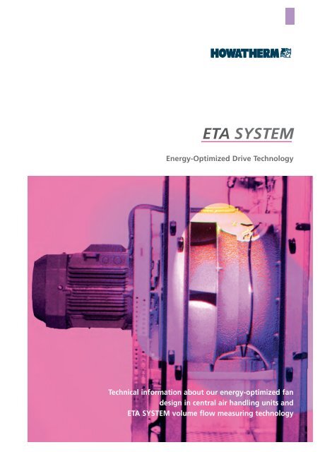
Energy-Optimized Drive Technology<br />
Technical information about our energy-optimized fan<br />
design in central air handling units and<br />
ETA SYSTEM volume flow measuring technology
2<br />
Systems<br />
information<br />
orientation<br />
messages<br />
insights<br />
Systems<br />
create helpful<br />
standards, saving us<br />
time to develop individual<br />
solutions.<br />
Energy-<br />
optimized<br />
<strong>HOWATHERM</strong> Klimatechnik has been specializing<br />
for nearly 30 years in the development<br />
and production of efficient<br />
systems for air handling applications to<br />
create and maintain comfortable indoor<br />
atmospheres for people.<br />
In the evaluation of contracts, operating<br />
costs have long been a key parameter. An<br />
environmentally responsible and economical<br />
use of resources, in both the manufacture<br />
and the use of AHU equipment, are<br />
important decision-making factors to specifiers<br />
and equipment users. Electrical<br />
power savings are a particularly important<br />
criterion.<br />
This is why <strong>HOWATHERM</strong>'s engineers, in<br />
their ongoing design improvement, have<br />
made the reduction of electrical power<br />
consumption an overriding objective.<br />
Investment and operating cost<br />
estimates<br />
An evaluation of our ETA SYSTEM versus<br />
conventional designs may appear to show<br />
initially higher investment costs.<br />
If the equipment side is included in these<br />
calculations - and about 60% of all systems<br />
require converter control - the frequency<br />
converter cannot generally be taken into<br />
account in the pre-investment analysis.<br />
Without the frequency converter, however,<br />
the investment cost of an ETA SYSTEM<br />
looks even more favorable when compared<br />
against conventional equipment, given<br />
the reduced mechanical complexity. And<br />
even if the frequency converter is included<br />
in the analysis, the ETA SYSTEM offers payback<br />
periods of 1 - 2 years on average.<br />
With the fundamental option of an ondemand<br />
flow control system, this payback<br />
period will be cut by another 50%.<br />
Evidently, the elimination of the belt drive<br />
can often make a second filter stage dispensable.<br />
Let us assume that you intend to replace a<br />
conventional AHU with one from our<br />
energy-optimized ETA SYSTEM range, all<br />
other design characteristics being equal.
In this case you will find the investment<br />
cost of the ETA system to be significantly<br />
lower, despite the frequency converter.<br />
Add to this estimate the facilitated startup<br />
process, convenient maintenance and<br />
cleaning behavior, fast and innovative diagnostics,<br />
continuous availability, etc., and<br />
you will discover a whole range of further<br />
key cost benefits.<br />
For more information on the various systems,<br />
simply give us a call on (++49)(6782)<br />
99990 or send an e-mail to the staff member<br />
in charge of your enquiry. You will<br />
find the addresses of our agencies and<br />
branch offices at www.howatherm.de.<br />
Our in-house and field staff will be glad to<br />
provide advice and support anytime, relying<br />
on advanced communication media.<br />
The reduced electrical power<br />
consumption of our systems is a result of<br />
the following factors:<br />
Optimized drive components with<br />
optional on-demand air flow control<br />
Optimized fan concept based on the<br />
plug-fan principle, reducing the<br />
influence of dynamic pressure effects<br />
Optimized mounting position with<br />
inlet and/or outlet guide vanes<br />
Optimized drive components (high<br />
efficiency motors, EFF1 / EFF2)<br />
Frequency converter based speed<br />
control<br />
Low electrical<br />
power input<br />
ETA System inlet<br />
device reduces air<br />
flow losses and<br />
improves the overall<br />
system efficiency.<br />
Patent protected in<br />
Germany.<br />
3
4<br />
Optimized design<br />
The ETA fan system is one of the most<br />
technologically advanced members of our<br />
central AHU range with energy-optimized<br />
drive systems.<br />
A comparison of the characteristic curves<br />
between the energy-optimized ETA SYSTEM<br />
and the conventional (standard) fan KZG<br />
SYSTEM reveals the difference: depending<br />
on the installation situation, the savings<br />
potential varies between approx. 15% at a<br />
static pressure increase of 1000 Pa and<br />
about 40% at 400 Pa.<br />
In conventional systems with spiral housing<br />
fans, a factor of 2 to 3 times the<br />
dynamic pressure can be viewed as pressure<br />
loss for the fan section.<br />
The ETA SYSTEM relies on the use of single-intake<br />
fans without spiral casing (plug<br />
fan type). The key benefits of this design<br />
are that dynamic pressure levels will<br />
account for a lower portion of the total<br />
pressure and that inflow and outflow pressure<br />
losses are reduced.<br />
Since the belt drive has thus been made<br />
redundant, the fan and motor are combined<br />
into a single compact unit. The nonencased<br />
impeller is mounted overhung on<br />
the motor shaft. This design eliminates losses<br />
due to, e.g., the belt pulley and bearing<br />
support struts in the fan intake, belt<br />
guards, wall influences, that means flow<br />
losses plus belt-related losses are minimized<br />
if not eliminated.<br />
We recommend the use of the ETA<br />
SYSTEM, regardless of volume flow, at<br />
total pressure levels up to 2000 Pa. The<br />
dynamic portion of the total pressure increase<br />
is relatively large at low pressures,<br />
so energy savings will be smaller.<br />
With the direct drive system mechanical<br />
losses are reduced, caused by the belt<br />
drive. Also speed control is achieved via a<br />
frequency converter integrated into the<br />
AHU. By using an asynchronous motor of<br />
increased efficiency, an additional 3 - 10%<br />
power consumption can be saved depending<br />
on system type (class EFF1 / EFF2).
On-demand air flow control<br />
The air flow control based on the frequency<br />
converter permits a speed adjustment in<br />
line with specific operating situations, e.g.,<br />
to allow or compensate for filter resistance,<br />
bypass operation, mixed flow mode, partload<br />
conditions, etc.<br />
In AHU equipment, a reliable measurement<br />
and control of the air flow rate contributes<br />
greatly to electrical power savings,<br />
true output performance, and operating<br />
reliability. For this reason we are offering<br />
an air flow rate measurement system (VSM)<br />
for ETA SYSTEM central AHUs. This system<br />
provides a direct reading of the air volume<br />
flow with a tolerance of ± 5% of the<br />
nominal air flow rate.<br />
In duct work measurements - a notoriously<br />
time-consuming and costly as well as inaccurate<br />
measuring principle - the measurement<br />
error is often more than 10 - 15%.<br />
Compared to constant-flow systems, it is<br />
possible to save a further 20 to 80% of the<br />
remaining electrical power consumption,<br />
depending on the requirement profile.<br />
The key to these advantages is the basic<br />
control capability provided by our ETA<br />
SYSTEM frequency converters.<br />
Design description<br />
5
6<br />
Optimum outflow<br />
Direct drive<br />
Controlability<br />
F7 F7<br />
Maintenance benefits and operating<br />
reliability<br />
In addition to our efforts to minimize the<br />
electrical power consumption of this range,<br />
maintenance behaviour and operating reliability<br />
were priority optimization objectives<br />
for our development engineers.<br />
In this respect, too, the elimination of the<br />
belt drive provides major advantages. The<br />
F7<br />
time-consuming and costly replacement of<br />
the belt, re-tensioning and belt monitoring<br />
are no longer an issue. Since no belt<br />
abrasion takes place, the pressure-side filter<br />
becomes redundant as well. And a<br />
non-existent fan bearing needs no maintenance<br />
and, of course, cannot fail.<br />
The load on the motor bearing exerted by<br />
the fan wheel is actually smaller than that<br />
imposed by belt tension. As a result, availability<br />
rates will be increased.<br />
Single intake fans with backward curved<br />
blade wheels, direct driven, turned 90° to<br />
the operating plane. Optimum inflow in<br />
the air direction without flow deflection<br />
losses.<br />
The arrangement of the motor right in the<br />
airflow results in optimum cooling. The<br />
use of high-efficiency motors additionally<br />
reduces the amount of energy converted<br />
into heat. Direct coupling to the fan eliminates<br />
wheel drive and belt losses; motor<br />
speed is varied by the frequency control<br />
action of a frequency converter.<br />
The basic control capability of the fan permits<br />
an on-demand flow control, e.g., to<br />
account for filter resistance in normal service,<br />
different resistances in mixed-flow<br />
mode, or varying resistance levels across<br />
the cooler during dry or demoisturizing<br />
operation.
Free intake, no bearings, no belt pulleys<br />
obstructing the cross-section, no interference<br />
from the casing walls.<br />
Optimum air outflow into the downstream<br />
component chamber with partial recovery<br />
of dynamic pressure. Low outlet losses,<br />
optimum air outflow into downstream<br />
component chambers. Outlet-side improvement<br />
of the local mixing efficiency by<br />
600%, meaning barely any temperature or<br />
velocity differences downstream of the fan<br />
- for optimum mixing.<br />
Air control and shutoff dampers based<br />
on the <strong>HOWATHERM</strong> SYSTEM: air-tight<br />
dampers are standard on our AHU´s, not<br />
just on units meeting hygiene requirements.<br />
<strong>HOWATHERM</strong> SYSTEM heat exchanger:<br />
Depending on the requirement situation,<br />
we recommend this component to be<br />
arranged on the pressure side for improved<br />
mixing conditions in the fan after a<br />
mixing section and superior handling of<br />
waste heat from the motor, particularly in<br />
cooling mode.<br />
Key design benefits<br />
of the ETA SYSTEM<br />
No need for a fan baseframe<br />
No belt guard, baffle plate, inspection<br />
sleeve or condensate drain<br />
No belt drive<br />
No fan bearings<br />
No motor adjustment carriage for<br />
belt tensioning<br />
Reduced installation length<br />
Improved inlet and outlet conditions,<br />
with better inflow into downstream<br />
components<br />
Freely definable air outlet connections<br />
Free intake<br />
Optimum hygiene<br />
7
8<br />
Other improvements<br />
Filterefficiency<br />
Filter<br />
Where two-stage filtration is inevitable<br />
we recommend the combination of an F7<br />
pre-filter with an F7 second filter stage.<br />
We have found this combination to achieve<br />
the same particle recovery rates as an F5 /<br />
F9 combination at greatly reduced filter<br />
change costs and lower average filter<br />
pressure-drop, which may average around<br />
200 Pa lower than F5 / F9 combination.<br />
In addition, the use of a single filter<br />
medium size will simplify maintenance.<br />
99,9%<br />
of the<br />
particles<br />
are smaller<br />
than 1µm
Filter<br />
With the use of a class F7 air filter, no prefilter<br />
is required. Quite the opposite is true<br />
- an upstream coarse particle filter will at<br />
best result in a 30% service life improvement,<br />
less than the cost of more frequent<br />
filter changes. A high-efficiency filter stage<br />
at the inlet into the unit ensures an optimum<br />
protection of downstream components<br />
while enhancing the cost-effectiveness<br />
of your filter media.<br />
Although a higher-class inlet filter needs<br />
to be replaced more frequently than the<br />
same filter stage combined with a pre-filter,<br />
the cost of changing filters (including<br />
the pre-filter) are higher in relative terms<br />
by a factor of about 1.5 than for a configuration<br />
without pre-filter. In addition<br />
according to VDI 6022 standart the first filter<br />
stage is to be changed at the latest<br />
once a year. Moreover, the volume of<br />
"special waste" accumulating in the form<br />
of filter media is minimized.<br />
For the ETA SYSTEM, this means that<br />
only a single filter stage will be used for<br />
fresh and supply air (except for hygienic<br />
AHU´s per DIN 1946 Part 4). Since no belt<br />
abrasion particles have to be dealt with,<br />
one single inlet-side air filter is enough -<br />
its outlet-side counterpart becomes redundant.<br />
Another key argument in favor of the ETA<br />
SYSTEM is hygiene.<br />
The elimination of the spiral casing makes<br />
for better hygiene conditions in the drive<br />
system, since non-hygienic matter will no<br />
longer accumulate on the interior housing<br />
surfaces.<br />
In addition, the system is easier to clean,<br />
since many areas in which impurities tended<br />
to collect are no longer part of the<br />
design (baseframe structure, motor carriage,<br />
belt guard, baffle plate, etc.). The<br />
impeller is accessible for maintenance from<br />
the operating side at any point - a major<br />
factor in central AHU equipment in hygienic<br />
service.<br />
For d<strong>eta</strong>ils on our HYGIENE system refer to<br />
www.howatherm.de.<br />
Function:<br />
Differential pressure<br />
to flow rate<br />
V = √∆ p (∆ p = differential pressure at the fan nozzle)<br />
or<br />
V = k* √∆ p [k = constant (depends on fan)]<br />
Fan design<br />
ETA SYSTEM - optimized<br />
fan concept<br />
based on the plugfan<br />
principle with<br />
volume flow measuring<br />
technology and<br />
frequency converter<br />
based speed control<br />
9
10<br />
Benefits of “smart”<br />
frequency<br />
converters<br />
Volume flow measu-<br />
ring technology<br />
ETA SYSTEM designs are generously sized,<br />
with flow velocities of around 2 m/s.<br />
This means that the droplet eleminator on<br />
the cooler can be void, resulting in a further<br />
decrease in internal pressure losses. In<br />
fact, the lower velocity reduces both the<br />
pressure loss (by a square correlation) and<br />
the electrical power consumption (by a<br />
third correlation). Moreover, the power<br />
consumption of the new drive concept is<br />
lower in relative terms at reduced pressures<br />
(approx. 15% savings at 1000 Pa, about<br />
40% at 400 Pa), implying still higher relative<br />
electrical power savings - with the result<br />
of further economic benefits.<br />
The power consumption of these units was<br />
measured on <strong>HOWATHERM</strong> test rigs and in<br />
RWTÜV trials and is EUROVENT-certified.<br />
An additional improvement feature is the<br />
execution of the fan casing in the thermally<br />
insulated ETA 40 T sectional structure.<br />
This design minimizes thermal bridges, and<br />
the casing is air-tight to DIN EN 1886 tightness<br />
class B.
Principle of operation<br />
We use the fan inlet nozzle as a flow<br />
nozzle for our measurement. Since the differential<br />
pressure changes subject to a<br />
square law with the volume flow or air<br />
velocity, this parameter is well suited as a<br />
standard of volumetric throughput. The<br />
ETA fan system ensures an undisturbed air<br />
flow in the inlet nozzle. No bearing support,<br />
belt pulley, belt or inlet guard components,<br />
etc., obstruct its cross-section. The<br />
air flows quite simply in a direction vertical<br />
to the nozzle plane. This explains the high<br />
degree of measuring accuracy obtained.<br />
The influence of the downstream fan<br />
impeller on the measuring accuracy is<br />
negligible. In extensive trials conducted on<br />
<strong>HOWATHERM</strong> test rigs, the inaccuracy caused<br />
by varying impeller speed was found<br />
not to exceed ± 0,5 %.<br />
The VSM system is based on the physical<br />
principle of differential pressure loss across<br />
a nozzle. It is the same principle that is<br />
commonly employed in test-rig measurements<br />
of the volumetric flow rate according<br />
to DIN 1952, DIN 24163, VDI 2041 or<br />
AMCA 210-67.<br />
The reference signal fed to the frequency<br />
converter may be in a 0-10 V voltage,<br />
4-20 mA or 0-20 mA current, or digital format.<br />
The advanced frequency converters employed<br />
by <strong>HOWATHERM</strong> also provide the<br />
possibility to create control loops without<br />
a separate control system. An integrated<br />
PID controller can maintain the volume<br />
flow or duct pressure constant to a specified<br />
setpoint value. The pressure or velocity<br />
ratio will thus remain unchanged regardless<br />
of the fan speed.<br />
The characteristic curves of our inlet<br />
nozzles were calibrated according to<br />
DIN 24 163 by RWTÜV on a voluntary<br />
basis.<br />
ETA System inlet device reduces air flow losses<br />
and improves the overall system efficiency.<br />
Patent protected in Germany.<br />
Control system<br />
11<br />
Practical advantages
12<br />
Energie savings and<br />
true output<br />
reporting<br />
Opimized operating<br />
convinience<br />
Air flow measuring<br />
system<br />
Control system: practical advantages<br />
Fan efficiency remains essentially unchanged<br />
throughout the operating<br />
speed range.<br />
A stable fan operating regime is achieved<br />
through the full fan speed range.<br />
Stepless speed changes can be effected<br />
via input signal control.<br />
Minimum and maximum speed levels can<br />
be preset.<br />
Motors may be of standard design.<br />
The need for soft starters is eliminated,<br />
given that the start-up current is limited<br />
to a defined value by the frequency converter.<br />
The additional electrical losses associated<br />
with the frequency converter are low<br />
(approx. 4% at full load).<br />
Control and monitoring systems can be<br />
easily interfaced with the frequency converter<br />
Control parameters facilitate optimum<br />
system adjustment.<br />
A constant volume flow regulation is<br />
provided.<br />
Simple control loops can be implemented<br />
even without higher-order controller<br />
or control system.<br />
System adjustments can be made at the<br />
touch of a button.<br />
Control options<br />
The differential pressure transducers provides<br />
a linearized output signal (0/4-20 mA)<br />
corresponding to the volumetric flow rate.<br />
This output signal is wired at our factory<br />
to the integrated frequency converter. It<br />
will thus serve as a reference signal for the<br />
frequency converter's built-in PID controller<br />
but may also be fed to an external higher-order<br />
control system. The 24 V d.c.<br />
power supply is likewise generated by the<br />
integrated frequency converter.<br />
Following parametrization of the frequency<br />
converter in our factory, the flow rate<br />
can be directly read off the frequency converter's<br />
display in m3 /h. In addition, the air<br />
flow can be kept constant to an externally<br />
defined setpoint via the built-in PID controller.<br />
Via an output signal, the volumetric<br />
flow rate may be transmitted to a higher-order<br />
control system, e.g., for efficiency<br />
optimization. For more d<strong>eta</strong>iled information<br />
refer to our HP-WRG system description.<br />
Varying due to changes in filter pressure<br />
drops, dry or wet cooler conditions, mixing<br />
flow mode, etc., will thus be compensated<br />
for by the control system.<br />
<strong>HOWATHERM</strong> is a member of the German<br />
Federation of Manufacturers of Air<br />
Handling Units (Herstellerverband<br />
Raumlufttechnische<br />
Geräte e.V.)<br />
Practical advantages<br />
The volumetric flow rate measurement<br />
embodied in our ETA SYSTEM helps to reduce<br />
the electrical power consumption<br />
and provides a true output picture, given<br />
that the actual volume flow will correspond<br />
exactly to the target value and no<br />
additional volume loss for conventional<br />
flow rate measurement (e.g., orifice plates,<br />
nozzles) is en-countered. The system is<br />
easier to adjust, requiring just the touch of<br />
a button on the frequency converter. The<br />
specific volume flow is digitally displayed<br />
throughout the adjustment process.
Reduced capital outlay is another benefit,<br />
since no extra measuring loops or instruments<br />
are needed. Time-consuming and<br />
inaccurate measuring routines have thus<br />
become a thing of the past. With the volume<br />
flow measuring system embodied into<br />
our ETA SYSTEM we have made a further<br />
contribution to enhancing the safety, energy<br />
efficiency and true-to-specification performance<br />
of your plant.<br />
Optimized operating convenience<br />
To facilitate diagnostics, a keypad and<br />
display for data and menus (IP 65 protection<br />
class) have been integrated into the<br />
front panel of the fan chamber. From this<br />
keypad, all control parameters can be entered<br />
using a menu-based microprocessor<br />
program. Operating variables such as r.p.m.,<br />
current, power, volumetric flow, kWh, etc.<br />
are displayed for effective maintenance<br />
support and transparency, ensuring that<br />
you will always know exactly how your system<br />
is performing. Parameters can be<br />
changed directly on the unit at any time;<br />
in the same way, parameter changes can<br />
be disabled where appropriate.<br />
Frequency converter installation<br />
site<br />
As a general rule, the system benefits outlined<br />
above (diagnostics, adjustment, etc.)<br />
are available only with the frequency con<br />
Specifications<br />
verter fitted inside the casing. Short cabling<br />
connections between the motor and<br />
frequency converters minimize power losses,<br />
and the integral installation of the frequency<br />
converter will ensure that it receives<br />
optimum cooling.<br />
Another aspect worth mentioning in this<br />
context is radio interference suppression. If<br />
an external installation site is used, it is<br />
possible to route so-called "antennas"<br />
through the building. We use mains filters<br />
to ensure electromagnetic compatibility.<br />
The radio interference suppression behaviour<br />
of our systems meet VDE 0875 Curve B<br />
specifications. <strong>HOWATHERM</strong> engineers will<br />
ensure a skilful and professional installation.<br />
Volumetric flow rate measurement based on pressure transducer.<br />
Differential pressure sensor with 0/4-20 mA signal output.<br />
Linearity ± 1,0 %<br />
Medium non-aggressive gases<br />
Output signal to frequency converter input 0/4-20 mA (RL> 1 kOhm )<br />
Power supply (via frequency converter) 24 V d.c. (± 0.20%)<br />
Protection class (casing) IP 54<br />
Protection class (keypad) IP 65<br />
Frequency converter<br />
installation site<br />
Spezifications<br />
13
For further information contact our inhouse<br />
or agencies, or visit us on the<br />
Internet.<br />
<strong>HOWATHERM</strong> Klimatechnik GmbH<br />
Innovative Ventilation and Air Handling<br />
Technology<br />
Degussagelände 11-15<br />
55767 Brücken / Germany<br />
Postal address:<br />
Postfach 1461<br />
55762 Birkenfeld / Germany<br />
Phone: (+49) (0)6782-99 99- 0<br />
Telefax: (+49) (0)6782-99 99-10<br />
0700<strong>HOWATHERM</strong><br />
E-mail: info@howatherm.de<br />
www.howatherm.de<br />
We enjoy working with you.<br />
SchillerKrenz-Gestaltung<br />
©<strong>HOWATHERM</strong> KLIMATECHNIK GMBH<br />
P004-07/03