A Generic and Scalable Pipeline for GPU Tetrahedral Grid ... - TUM
A Generic and Scalable Pipeline for GPU Tetrahedral Grid ... - TUM
A Generic and Scalable Pipeline for GPU Tetrahedral Grid ... - TUM

You also want an ePaper? Increase the reach of your titles
YUMPU automatically turns print PDFs into web optimized ePapers that Google loves.
To avoid the memory overhead induced by precomputations,<br />
element matrices can be calculated in<br />
turn <strong>for</strong> every sample point. But then the same computations,<br />
including multiple memory access operations to<br />
fetch the respective coordinates, have to be per<strong>for</strong>med<br />
<strong>for</strong> all sample points in the interior of a single element,<br />
thereby wasting a significant portion of the <strong>GPU</strong>s compute<br />
power. As be<strong>for</strong>e, identifiers are required to access vertex<br />
coordinates, <strong>and</strong> thus a shared vertex array cannot be used.<br />
1.1 Contribution<br />
In this paper we present a <strong>GPU</strong> pipeline <strong>for</strong> the rendering of<br />
tetrahedral grids that avoids the a<strong>for</strong>ementioned drawbacks.<br />
This pipeline is scalable with respect to both large data sets<br />
as well as future graphics hardware. The proposed method<br />
has the following properties:<br />
• Per-element calculations are per<strong>for</strong>med only once.<br />
• <strong>Tetrahedral</strong> vertices <strong>and</strong> attributes can be shared in<br />
vertex <strong>and</strong> attribute arrays.<br />
• Besides the shared vertex <strong>and</strong> attribute arrays no additional<br />
memory is required on the <strong>GPU</strong>.<br />
• Re-sampling of (de<strong>for</strong>ming) tetrahedral elements is per<strong>for</strong>med<br />
using a minimal memory footprint.<br />
1.2 System Overview<br />
To achieve our goal we propose a generic <strong>and</strong> scalable <strong>GPU</strong><br />
rendering pipeline <strong>for</strong> tetrahedral elements. This pipeline is<br />
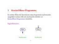
illustrated in Figure 2. It consists of multiple stages per<strong>for</strong>ming<br />
element assembly, primitive construction, rasterization<br />
<strong>and</strong> per-fragment operations.<br />
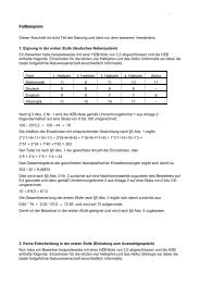
Figure 2: Overview of the <strong>GPU</strong> rendering pipeline.<br />
To render a tetrahedral element the pipeline is fed with one<br />
single vertex, which carries all in<strong>for</strong>mation necessary to assemble<br />
the element geometry on the <strong>GPU</strong>. This stage is described<br />
in Section 3.1. Assembled geometry is then passed<br />
to the construction stage where a renderable representation<br />
is built.<br />
The construction stage is explicitly designed to account <strong>for</strong><br />
the functionality on upcoming graphics hardware. With Direct3D<br />
10 compliant hardware <strong>and</strong> geometry shaders [1] it<br />
will be possible to create additional geometry on the graphics<br />
subsystem. In particular, triangle strips or fans composed<br />
of several vertices, each of which can be assigned individual<br />
per-vertex attributes, can be spawned from one single<br />
vertex. As the geometry shader itself can per<strong>for</strong>m arithmetic<br />
<strong>and</strong> texture access operations, these attributes can be<br />
computed in account of the application specific needs. By<br />
using the a<strong>for</strong>ementioned functionality the renderable representation<br />
can be constructed in turn without sacrificing<br />
the feed-<strong>for</strong>ward nature of the proposed rendering pipeline.<br />
Section 3.2 gives in-depth details on this stage.<br />
As hardware-assisted geometry shaders are not yet available<br />
on current <strong>GPU</strong>s we have implemented the proposed<br />
pipeline using the DirectX9 SDK. This SDK provides a software<br />
emulation of the entire Direct3D 10 pipeline, <strong>and</strong> it is<br />
available under the recent Microsoft Vista beta version. Un<strong>for</strong>tunately,<br />
neither does this emulation provide meaningful<br />
per<strong>for</strong>mance measures nor does it allow to estimate relative<br />
timings between the pipeline stages. Nevertheless, the implementation<br />
using this software emulation clearly demonstrates<br />
that the proposed pipeline concept can effectively be<br />
mapped onto upcoming <strong>GPU</strong>s in the very near future.<br />
To verify the efficiency of the intended method we propose<br />
an emulation of the primitive construction step using the<br />
render-to-vertexbuffer functionality. The specific implementation<br />
will be discussed in Section 6. Although this emulation<br />
requires additional rendering passes it still results in<br />
frame rates superior to those that can be achieved by the<br />
fastest methods known so far.<br />
The renderable representation is then sent to the <strong>GPU</strong> rasterizer.<br />
On the fragment level a number of different rendering<br />
techniques can be per<strong>for</strong>med <strong>for</strong> each tetrahedron,<br />
including a ray-based approach, iso-surface rendering <strong>and</strong><br />
cell projection. The discussion in the remainder of this paper<br />
will be focused on the first approach, <strong>and</strong> we will briefly<br />
describe the other rendering variants in Sections 4 <strong>and</strong> 5.<br />
The ray-based approach operates similar to ray-casting by<br />
sampling the data along the view rays. In contrast, however,<br />
it does not compute <strong>for</strong> each ray the set of elements consecutively<br />
hit along that ray, but it lets the rasterizer compute<br />
<strong>for</strong> each element the set of rays intersecting that element.<br />
The interpolation of the scalar field at the sample points in<br />
the interior of each element is then per<strong>for</strong>med in the fragment<br />
stage, <strong>and</strong> the results are finally blended into the color<br />
buffer.<br />
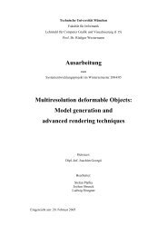
The approach as described requires the tetrahedral elements<br />
to be sampled in correct visibility order. To avoid the explicit<br />
computation of this ordering we first partition the eye<br />
coordinate space into spherical shells around the point of<br />
view. Figure 3 illustrates this partitioning strategy.<br />
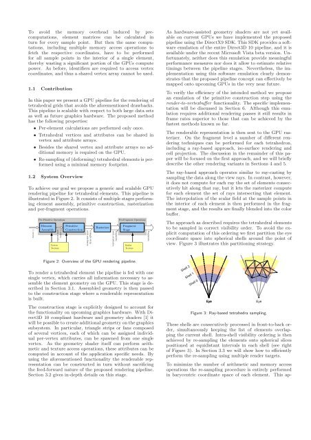
Figure 3: Ray-based tetrahedra sampling.<br />
These shells are consecutively processed in front-to-back order,<br />
simultaneously keeping the list of elements overlapping<br />
the current shell. Intra-shell visibility ordering is then<br />
achieved by re-sampling the elements onto spherical slices<br />
positioned at equidistant intervals in each shell (see right<br />
of Figure 3). In Section 3.3 we will show how to efficiently<br />
per<strong>for</strong>m the re-sampling using multiple render targets.<br />
To minimize the number of arithmetic <strong>and</strong> memory access<br />
operations the re-sampling procedure is entirely per<strong>for</strong>med<br />
in barycentric coordinate space of each element. This ap-