A Generic and Scalable Pipeline for GPU Tetrahedral Grid ... - TUM
A Generic and Scalable Pipeline for GPU Tetrahedral Grid ... - TUM
A Generic and Scalable Pipeline for GPU Tetrahedral Grid ... - TUM

Create successful ePaper yourself
Turn your PDF publications into a flip-book with our unique Google optimized e-Paper software.
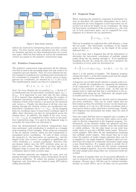
Figure 4: Data stream overview<br />
indices are resolved by interpreting them as texture coordinates.<br />
Via four texture access operations the four vertices<br />
are obtained, <strong>and</strong> they are then trans<strong>for</strong>med into eye coordinate<br />
space. Both the four indices as well as the trans<strong>for</strong>med<br />
vertices are passed to the primitive construction stage.<br />
3.2 Primitive Construction<br />
The primitive construction stage generates all the in<strong>for</strong>mation<br />
that is used in the upcoming stages but only needs to be<br />
computed once per element. First, <strong>for</strong> every element the matrix<br />
required to trans<strong>for</strong>m eye coordinates into local barycentric<br />
coordinates is computed. The vertices, given in homogeneous<br />
eye coordinates, are denoted by vi, i ∈ {0, 1, 2,3}.<br />
The trans<strong>for</strong>mation matrix can then be computed as<br />
B = � v0 v1 v2 v3<br />
� −1 .<br />
Next, <strong>for</strong> every element the eye position veye = (0,0, 0,1) T<br />
is trans<strong>for</strong>med into its barycentric coordinate space: beye =<br />
B veye. It is important to note that only the last column<br />
of B is required thus significantly reducing the number of<br />
arithmetic operations to be per<strong>for</strong>med. The barycentric coordinates<br />
of each of the vertices vi are given by the canonical<br />
unit vectors ei. Finally, the directions of all four view rays<br />
passing through the element vertices are trans<strong>for</strong>med into<br />
barycentric coordinates via bi = ei − beye. As the mapping<br />
from eye coordinate space to barycentric coordinate space is<br />
affine, these directions can later be interpolated across the<br />
element faces. In addition, the length of the view vector,<br />
li = ||vi − veye||2, is computed <strong>for</strong> every vertex in the primitive<br />
construction stage. It is used in the fragment stage to<br />
normalize the barycentric ray directions bi.<br />
Once the a<strong>for</strong>ementioned per-element computations have<br />
been per<strong>for</strong>med, each tetrahedron is rendered as a triangle<br />
strip consisting of four triangles. These strips are composed<br />
of the six element vertices, which are first trans<strong>for</strong>med to<br />
normalized device coordinates. To each of these vertices<br />
the respective bi, the barycentric eye position beye <strong>and</strong> the<br />
length of the view vector li are assigned as additional pervertex<br />
attributes, i.e. texture coordinates. Moreover, four<br />
per-element indices into the <strong>GPU</strong> attribute array are assigned<br />
to each vertex. These indices are later used in the<br />
fragment stage to access the scalar field or the 3D texture<br />
coordinates used to bind a texture map.<br />
The rasterizer generates one fragment <strong>for</strong> every view ray<br />
passing through a tetrahedron, <strong>and</strong> it interpolates the given<br />
per-vertex attributes. To reduce the number of generated<br />
fragments only front-faces are rendered using API built-in<br />
culling functionality.<br />
3.3 Fragment Stage<br />
When rendering the primitives composed of attributed vertices<br />
as described, the rasterizer interpolates the bi <strong>and</strong> li<br />
<strong>and</strong> generates <strong>for</strong> every fragment a local barycentric ray direction<br />
b as well as its length l in eye coordinates. By using<br />
the barycentric coordinates of the eye position beye, the view<br />
ray in local barycentric space can be computed <strong>for</strong> every<br />
fragment as (t denotes the ray parameter)<br />
b<br />
· t + beye, t > 0.<br />
l<br />
This ray is sampled on a spherical slice with distance zs from<br />
the eye point. The barycentric coordinate of the sample<br />
point is obtained by setting t as the depth of the actual<br />
spherical slice, zs.<br />
It is now clear that a fragment has all the in<strong>for</strong>mation to<br />
determine the barycentric coordinates of multiple sample<br />
points along the ray passing through it. If an equidistant<br />
sampling step size ∆zs along the view rays is assumed, the<br />
coordinates of every point are determined as<br />
b k = b<br />
· (zs + k · ∆zs) + beye, k ∈ {0, 1, . . . , n − 1}. (1)<br />
l<br />
where n is the number of samples. The fragment program<br />
obtains the depth zs of the first sample point <strong>and</strong> the sample<br />
spacing ∆zs as constant parameters.<br />
A fragment can trivially decide whether a sample point is inside<br />
or outside the tetrahedron by comparing the minimum<br />
of all components of b k with zero. A minimum greater or<br />
equal to zero indicates an interior point. In this case the<br />
sample point is valid <strong>and</strong> thus has a contribution to the accumulated<br />
color along the ray. Otherwise, the sample point<br />
is invalid <strong>and</strong> has to be discarded.<br />
The barycentric coordinates are directly used to interpolate<br />
per-vertex attributes. This can be scalar values that are<br />
first looked up from the attribute texture via the issued pervertex<br />
indices, or it can be a 3D texture coordinate that is<br />
then used to fetch a scalar value from a texture map. Finally,<br />
each fragment has determined one scalar value <strong>for</strong> each of<br />
its n samples.<br />
Once the scalar field has been re-sampled onto a number of<br />
sample points along the view-rays these values can in principle<br />
be directly composited in the fragment program. Un<strong>for</strong>tunately,<br />
as the elements within one spherical cell have<br />
not been rendered in correct visibility order this would lead<br />
to visible artifacts. On the other h<strong>and</strong> we can write four<br />
scalar values at once into a RGBA render target. Moreover,<br />
recent graphics APIs allow <strong>for</strong> the simultaneous rendering<br />
into multiple render targets. This means that up to four<br />
times the number of render targets spherical slices can be<br />
re-sampled by one single fragment. Sampled values are rendered<br />
into the respective component <strong>and</strong> render target using<br />
a max blend function. If a sample point is outside the element,<br />
a zero value is written into the texture component<br />
<strong>and</strong> the sample is ignored. As no two tetrahedra can contain<br />
the same sample point along either ray, erroneous results are<br />
avoided.<br />
The number of samples that can be processed efficiently at<br />
once is restricted by the output b<strong>and</strong>width of the fragment<br />
program. Because up to 128 bits can be rendered simultaneously<br />
on recent <strong>GPU</strong>s, up to 16 slices can be processed