Operating Instructions Multifunctional Power ... - Camille Bauer AG
Operating Instructions Multifunctional Power ... - Camille Bauer AG
Operating Instructions Multifunctional Power ... - Camille Bauer AG

You also want an ePaper? Increase the reach of your titles
YUMPU automatically turns print PDFs into web optimized ePapers that Google loves.
<strong>Operating</strong> <strong>Instructions</strong><br />
<strong>Multifunctional</strong> <strong>Power</strong><br />
Monitor with System Analysis<br />
SINEAX A 230 / A 230s<br />
<strong>Camille</strong> <strong>Bauer</strong> LTD<br />
Aargauerstrasse 7<br />
CH-5610 Wohlen/Switzerland<br />
Phone +41 56 618 21 11<br />
Fax +41 56 618 35 35<br />
info@camillebauer.com<br />
www.camillebauer.com<br />
Safety notes<br />
A 230 / A230s Be 154 807-09 01.11<br />
The instruments must only be disposed of in the<br />
correct way!<br />
The installation and commissioning should only be carried out by trained<br />
personnel.<br />
Check the following points before commissioning:<br />
– that the maximum values for all the connections are not exceeded, see<br />
the “Technical data” section,<br />
– that the connection wires are not damaged, and that they are not live<br />
during wiring,<br />
– that the power fl ow direction, and the phase rotation are correct.<br />
The instrument must be taken out of service if safe operation is no longer<br />
possible (e.g. visible damage). In this case, all the connections must<br />
be switched off. The instrument must be returned to the factory or to an<br />
authorized service dealer.<br />
It is forbidden to open the housing and to make modifi cations to the instrument.<br />
The instrument is not equipped with an integrated circuit breaker.<br />
During installation check that a labeled switch is installed and that it can<br />
easily be reached by the operators.<br />
Unauthorized repair or alteration of the unit invalidates the warranty.<br />
Contents Page<br />
Brief description 2<br />
Technical data 2<br />
Commissioning 3<br />
Electrical connections 3<br />
Measured value display 5<br />
Operation 9<br />
Display window 10<br />
Programming 13<br />
Programming charts 20<br />
Dimensional drawing 22<br />
1
Brief description<br />
Panel mounting instrument A230 with dimensions 144x144x46 mm<br />
resp. A230s with dimensions 96 x 96 x 46 mm. Four-quadrant measurement<br />
for power system and consumption analysis in single and<br />
multi-phase AC systems. Three large LED displays with four digits<br />
plus sign. The converter data are included for direct display and<br />
further processing. Confi gurable display settings for user specifi c<br />
presentation, integrated energy meters, impulse counters, and limit<br />
value indication. Comprehensive average value and max./min. value<br />
functions. Harmonic analysis and THD measurement. Determination<br />
of the neutral wire current. Asymmetry factor and neutral point voltage<br />
shift. Two switched outputs for the control of impulse counters,<br />
or for signalling limit alarms.<br />
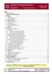
Technical data<br />
(for more detailed information please see datasheet, download under<br />
www.camillebauer.com)<br />
Measuring inputs<br />
Nominal frequency: 50, 60 Hz<br />
Nominal input voltage: Phase-phase: 500 V<br />
Phase - N: 290 V<br />
Nominal input current: 5 A or 1 A<br />
Continuous thermal rating of inputs<br />
2<br />
10 A at 346 V in single-phase AC system<br />
10 A at 600 V in three-phase system<br />
Short-time thermal rating of inputs<br />
Input variable<br />
Number of<br />
inputs<br />
Duration<br />
of<br />
overloads<br />
577 V LN 10 1 s 10 s<br />
100 A 10 1 s 100 s<br />
100 A 5 3 s 5 min<br />
Interval between<br />
two overloads<br />
Measuring ranges<br />
U, I, S: ≤ 120% of nominal value<br />
P, Q: ≤ ± 120% of nominal value<br />
F: 45 to 65 Hz<br />
cosϕ: ± 1<br />
Display<br />
The measurement display is 4 digit (frequency) and right justifi ed.<br />
Energy values are displayed with 8 digits.<br />
Zero value suppression<br />
PF resp cosϕ: Display ---, if Sx < 0.2% Snenn<br />
Currents: Display 0, if Ix < 0.1% Inenn<br />
unb. U: Display 0, if Ø U < 5% Unenn<br />
Pulse/Limit value outputs<br />
Depending on the function selected, the two digital outputs can<br />
be used either as pulse outputs for actual and reactive energy or<br />
as limit signals.<br />
The outputs are passive, and are galvanically isolated from all the<br />
other circuits by opto-couplers. They are suitable to drive tariff<br />
devices (S0-standard DIN 43 864), or 24 V relais.<br />
U ≤ 40 V DC (OFF: leakage current ≤ 0.1 mA)<br />
ext<br />
≤ 150 mA (ON: terminal voltage ≤ 1.2 V)<br />
I L<br />
SO2<br />
SO1<br />
20<br />
21<br />
22<br />
U ext<br />
Limit value outputs<br />
The measured values can be freely allocated.<br />
RL<br />
RL<br />
U<br />
U<br />
t<br />
e.g. energy import<br />
e.g. limit value output<br />
Pulse outputs<br />
Active and reactive energy pulses can be generated for the control<br />
of electronic and electromechanical counters.<br />
<strong>Power</strong> supply<br />
DC-, AC power pack 50 to 400 Hz<br />
100 to 230 V AC/DC ±15% or 24 to 60 V AC/DC ±15%<br />
(UL) 85 bis 125 V DC<br />
<strong>Power</strong> consumption: 3 VA (without extension module)<br />
A marked and easily accessible current limiting<br />
switch has to be arranged in the vicinity of the device<br />
for turning off the power supply. Fusing should be<br />
10 Amps or less and must be rated for the available<br />
voltage and fault current.<br />
Reference conditions<br />
acc. to IEC 688 resp EN 60 688<br />
Sine 50 - 60 Hz, 15 - 30°, application group II<br />
Measurement accuracy (related to nominal value)<br />
Current, voltage ± 0.2%<br />
<strong>Power</strong> ± 0.5%<br />
<strong>Power</strong> factor ± 0.5%<br />
Energy ± 0.5%<br />
Frequency<br />
Environmental conditions<br />
± 0.02 Hz (abs.)<br />
<strong>Operating</strong> temperature: -10 to +55 °C<br />
Storage temperature: -25 to +70 °C<br />
Humidity relative: ≤ 75%<br />
Altitude:<br />
Indoor use statement<br />
2000 m max.<br />
Safety<br />
Protection class: II (voltage inputs with protection<br />
impedances)<br />
Measuring category: III<br />
Pollution degree: 2<br />
Measurement voltage: 300 V<br />
Test voltage: Between current inputs, power<br />
supply, digital outputs, terminals<br />
of the plugged-in module: 3700 V /<br />
50 Hz / 1 min.<br />
On voltage inputs:<br />
4.25 kV 1.2/50 μs<br />
Module connections: The pin rail at the back is connected<br />
to the voltage inputs via a protection<br />
impedance. Only the permitted<br />
modules can be plugged-in!<br />
Enclosure protection: IP 20
Commissioning<br />
The multifunctional power monitor is made operational by switching<br />
on the power supply. The following appears sequentially on the<br />
display:<br />
1. Segment tests: all the segments of the displays and all the LEDs<br />
are lit for 2 s.<br />
2. Version of the software: e.g. A 230 1.04<br />
3. The 3 line voltages at switching on.<br />
Loss of the power supply<br />
All the values confi gured remain during a loss of the power supply.<br />
On reconnecting the power supply, the last mode selected is displayed.<br />
Note of maintenance<br />
No maintenance is required.<br />
Electrical connections<br />
Safety Disconnects<br />
The mains supply power to the instrument must be<br />
installed downstream from a switched current limiting<br />
device.<br />
The circuit protection device should be 20 Amps or<br />
less, and must be rated for the available voltage and<br />
fault current; 5 Amp fuses are preferred.<br />
WARNING<br />
All mains supply power to the instrument must be<br />
installed downstream from a switched current limiting<br />
device.<br />
The circuit protection device should be 20 Amps or<br />
less, and must be rated for the available voltage and<br />
fault current; 5 Amps are preferred.<br />
The national provisions (e.g. in Germany VDE 0100<br />
“Conditions concerning the erection of heavy current<br />
facilities with rated voltages below 1000 V”) have to<br />
be observed in the installation and material selection<br />
of electric lines!<br />
When using external PT’s or CT’s refer to the<br />
manufacturer’s information for connections for voltage<br />
and current monitoring.<br />
The electrical connections are identical for the SINEAX A 230 and<br />
A 230s.<br />
Measuring input, acc. to measuring mode<br />
1 2 +<br />
I1<br />
U1<br />
Pulse /<br />
Limit value output<br />
I2<br />
U2<br />
Jumper<br />
I3<br />
U3<br />
1 2 3 4 5 6 7 8 9 11<br />
I1 U1 I1 I2 U2 I2 I3 U3 I3 N<br />
UL: 3~300V 5A 50/60Hz CAT III<br />
IEC: 3~500/290V 5A 50/60Hz CAT III<br />
SINEAX A230s Mat: 123456/1234567/001<br />
Man: 10/02<br />
NLBxxxx<br />
SO<br />
1 2<br />
LOCK<br />
<strong>Camille</strong> <strong>Bauer</strong> <strong>AG</strong><br />
Switzerland<br />
100-230V AC<br />
85-125V DC<br />
50-400Hz 3VA<br />
22 21 20<br />
14 15<br />
N<br />
<strong>Power</strong> supply<br />
No. 1<br />
Symbol Meaning<br />
CAT III<br />
Connecting modes<br />
System/<br />
application<br />
Single phase<br />
AC system<br />
3-wire<br />
3-phase<br />
symmetric<br />
load<br />
I: L1<br />
Device may only be disposed of in a professional<br />
manner!<br />
Double insulation, device of protection class 2<br />
CE conformity mark. The device fulfi lls the requirements<br />
of the applicable EC directives.<br />
Products with this mark comply with both the<br />
Canadian (CSA) and the American (UL) requirements<br />
Caution! General hazard point. Read the operating<br />
instructions.<br />
General symbol: Input<br />
General symbol: Output<br />
General symbol: <strong>Power</strong> supply<br />
Measurement category CAT III for current and voltage<br />
inputs<br />
L1<br />
N<br />
L1<br />
N<br />
L1<br />
L2<br />
L3<br />
u<br />
U<br />
2 11 1 3<br />
v<br />
V<br />
k l<br />
K L<br />
2 5 8 1 3<br />
u<br />
v<br />
U V<br />
L1<br />
L2<br />
L3<br />
2 11 1 3<br />
2 5 8 1 3<br />
u<br />
U<br />
v<br />
V<br />
k<br />
K L<br />
Terminals<br />
l<br />
L1<br />
N<br />
L1<br />
L2<br />
L3<br />
2 11 1 3<br />
k l<br />
K L<br />
2 5 8 1 3<br />
k l<br />
K L<br />
Connect the voltage according to the following<br />
table for current measurement in L2 or L3:<br />
Current<br />
transf.<br />
Terminals 2 5 8<br />
L2 1 3 L2 L3 L1<br />
L3 1 3 L3 L1 L2<br />
3
System/<br />
application<br />
4-wire<br />
3-phase<br />
symmetric<br />
load<br />
I: L1<br />
3-wire<br />
3-phase<br />
asymmetric<br />
load<br />
4<br />
3-wire<br />
3-phase<br />
asymmetric<br />
load,<br />
Aron<br />
L1<br />
L2<br />
L3<br />
N<br />
L1<br />
L2<br />
L3<br />
N<br />
L1<br />
L2<br />
L3<br />
Terminals<br />
2 5 8 1 3 7 9<br />
u<br />
v<br />
U V<br />
L1<br />
L2<br />
L3<br />
2<br />
u<br />
U<br />
u<br />
11 1 3<br />
2 11 1 3<br />
U<br />
v<br />
V<br />
v<br />
V<br />
k l<br />
K L<br />
2 5 8 1 3 7 9<br />
k l<br />
K L k l<br />
K L<br />
L1<br />
L2<br />
L3<br />
N<br />
L1<br />
L2<br />
L3<br />
L1<br />
L2<br />
L3<br />
2 5 8 1 3 7 9<br />
u<br />
x<br />
2 11 1 3<br />
u<br />
x<br />
u<br />
x<br />
X X X<br />
U U U<br />
k l<br />
K L<br />
Connect the voltage according to the following<br />
table for current measurement in L2 or L3:<br />
Current transf. Terminals 2 11<br />
L2 1 3 L2 N<br />
L3 1 3 L3 N<br />
L1<br />
L2<br />
L3<br />
L1<br />
L2<br />
L3<br />
L1<br />
L2<br />
L3<br />
2 5 8 1 3 4 6 7 9<br />
2 5 8 1 3 4 6 7 9<br />
k l<br />
K L<br />
k l<br />
K L<br />
k l<br />
K L<br />
2 5 8 11 1 3 4 6 7 9<br />
u<br />
x<br />
u<br />
x<br />
u<br />
x<br />
X X X<br />
U U U<br />
k l<br />
K L<br />
k l<br />
K L<br />
k l<br />
K L<br />
3 single-pole insulated voltage transformers in<br />
high-voltage system<br />
k l<br />
K L k l<br />
k l<br />
K L<br />
2 5 8 1 3 7 9<br />
K L k l<br />
K L<br />
System/<br />
application<br />
4-wire<br />
3-phase<br />
asymmetric<br />
load<br />
4-wire<br />
3-phase<br />
asymmetric<br />
load,<br />
Open-Y<br />
L1<br />
L2<br />
L3<br />
N<br />
L1<br />
L2<br />
L3<br />
L1<br />
L2<br />
L3<br />
N<br />
L1<br />
L2<br />
L3<br />
N<br />
N<br />
L1<br />
L2<br />
L3<br />
N<br />
Terminals<br />
2 5 8 11 1 3 4 6 7 9<br />
2 5 8 11 1 3 4 6 7 9<br />
2 5 8 11 1 3 4 6 7 9<br />
3 single-pole insulated voltage transformers<br />
in high-voltage system<br />
2 8 11 1 3 4 6 7 9<br />
u u<br />
x x<br />
u<br />
x<br />
X X<br />
U U<br />
u<br />
x<br />
k<br />
u<br />
x<br />
X X X<br />
U U U<br />
k l<br />
K L<br />
l<br />
k l<br />
K L<br />
k l<br />
K L<br />
K L L<br />
k<br />
k l<br />
K L<br />
Low-voltage system<br />
K L<br />
l<br />
k l<br />
K L<br />
k l<br />
K L<br />
k l<br />
K L<br />
1 2 3 4 5 6 7 8 9 11<br />
k<br />
k l<br />
K L<br />
k l<br />
K L<br />
K L<br />
2 single-pole insulated voltage transformers<br />
in high-voltage system<br />
l
Measured value display<br />
Maximum<br />
Sign<br />
Minimum<br />
Left LED<br />
group<br />
Abbreviations and symbols<br />
7-segment<br />
top<br />
P<br />
7-segment<br />
centre<br />
Display Clear<br />
oL Overload, out of range indicator<br />
U.nE Neutral point voltage shift (U neutral-earth)<br />
unb.U Voltage asymmetry factor (unbalance U)<br />
in Neutral current<br />
SYSt. System power<br />
x.xx i ϕ <strong>Power</strong> factor incoming inductive<br />
x.xx c ϕ <strong>Power</strong> factor incoming capacitive<br />
- x.xx i ϕ <strong>Power</strong> factor outgoing inductive<br />
- x.xx c ϕ <strong>Power</strong> factor outgoing capacitive<br />
inc Incoming<br />
out Outgoing<br />
Available measurement data<br />
(at connection mode 4-wire asymmetric load)<br />
LED<br />
group<br />
left<br />
7-segment<br />
bottom<br />
k: Kilo<br />
M: Mega<br />
M+k: Giga<br />
2 3<br />
Bottom LED group<br />
cos-Phi<br />
Average value<br />
Sum or system<br />
value<br />
Right LED<br />
group<br />
Bimetal symbol (I-avg)<br />
Delta voltage<br />
Integration symbol<br />
(interval average value)<br />
Phase 3<br />
Phase 2<br />
Phase 1<br />
ind Inductive<br />
CAP Capacitive<br />
.H Energy high tariff<br />
.L Energy low tariff<br />
thd.U THD-U<br />
thd.i THD-I<br />
trnd Interval power: Trend<br />
t-0…t-4 Interval power: last to fi fth last interval<br />
H2.U…H15.U 2 nd - 15 th harmonic U<br />
H2.i…H15.i 2 nd - 15 th harmonic I<br />
Example<br />
7-segm.<br />
display<br />
Example<br />
7-segm.<br />
display<br />
Example<br />
7-segm.<br />
display<br />
LED<br />
group<br />
right<br />
LED<br />
group<br />
bottom<br />
(t c b) top centre bottom<br />
Phase voltages: U1, U2, U3 230.2 231.1 229.9 V L1 L2 L3<br />
Maximum values: U1-max, U2-max, U3-max 235.1 236.4 231.2 V L1 L2 L3<br />
Minimum values: U1-min, U2-min, U3-min 227.8 226.6 225.7 V L1 L2 L3<br />
Delta voltages: U12, U23, U31 400.0 402.5 398.4 V Δ<br />
Maximum values: U12-max, U23-max, U31-max 405.2 406.4 403.3 V Δ<br />
Minimum values: U12-min, U23-min, U31-min 395.5 397.4 396.8 V<br />
Neutral point voltage shift: UNE and UNE-max U.nE 2.3 8.6 V<br />
Voltage asymmetry factor (unbalanced U) unb.U 1.4 6.2 %<br />
Phase currents: I1,I2, I3 11.54 10.98 10.23 A L1 L2 L3<br />
Maximum values: I1-max, I2-max, I3-max 12.65 11.86 11.07 A L1 L2 L3<br />
Average values: I1avg, I2avg, I3avg<br />
(bimetal-15minutes)<br />
7.23 6.86 6.46 A L1 L2 L3<br />
Max. average values: I1avg-max, I2avg-max,<br />
I3avg-max (slave pointer -15 minutes)<br />
7.98 7.48 6.98 A L1 L2 L3<br />
Neutral current: IN and IN-max in 1.13 2.75 A<br />
Active power: P1, P2, P3 a) 2240 2032 1491 W L1 L2 L3<br />
Maximum values: P1-max, P2-max, P3-max a) 2554 2825 2482 W L1 L2 L3<br />
Continuation see next page!<br />
5
Available measurement data<br />
(at connection mode 4-wire asymmetric load)<br />
6<br />
LED<br />
group<br />
left<br />
Example<br />
7-segm.<br />
display<br />
Example<br />
7-segm.<br />
display<br />
Example<br />
7-segm.<br />
display<br />
(t c b) top centre bottom<br />
Active power system: P and P-max a) SYSt. 5.76 7.86 kW<br />
LED<br />
group<br />
right<br />
LED<br />
group<br />
bottom<br />
Reactive power: Q1, Q2, Q3 b) 1078 393 721 VAr L1 L2 L3<br />
Maximum values: Q1-max, Q2-max, Q3-max b) 1704 561 1027 VAr L1 L2 L3<br />
Reactive power system: Q and Q-max b) SYSt. 2.19 3.29 kVAr<br />
Apparent powers: S1, S2, S3 2281 2157 2089 VA L1 L2 L3<br />
Maximum values: S1-max, S2-max, S3-max 3066 2874 2682 VA L1 L2 L3<br />
Apparent power system: S and S-max SYSt. 6.64 8.11 kVA<br />
<strong>Power</strong> factors: PF1, PF2, PF3 a) 0.82c 0.97c 0.92c ϕ L1 L2 L3<br />
PF-system, PF-min-inductive-incoming,<br />
PF-min-capacitive-incoming<br />
a) 0.90c – – – i 0.72c ϕ<br />
PF-system, PF-min-inductive-outgoing,<br />
PF-min-capacitive-outgoing<br />
a)<br />
– –<br />
0.90c – – – i – – – c ϕ<br />
Frequency: F-max, F-actual, F-min 50.14 50.03 49.78 Hz<br />
Active power incoming EP high tariff 4589 2356 inc.H kWh ∑<br />
Active power incoming EP low tariff c) 1234 5678 inc.L kWh ∑<br />
Active power outgoing EP high tariff 4589 2356 out.H kWh ∑<br />
Active power outgoing EP low tariff c) 1234 5678 out.L kWh ∑<br />
Reactive power inductive EQ high tariff d) 9876 5432 ind.H kVarh ∑<br />
Reactive power inductive EQ low tariff c) d) 1234 9876 ind.L kVarh ∑<br />
Reactive power capacitive EQ high tariff d) 76 5432 CAP.H kVarh ∑<br />
Reactive power capacitive EQ low tariff c) d) 234 9876 CAP.L kVarh ∑<br />
Reactive power incoming EQ high tariff e) 9876 5432 inc.H kVarh ∑<br />
Reactive power incoming EQ low tariff c) e) 1234 9876 inc.L kVarh ∑<br />
Reactive power outgoing EQ high tariff e) 76 5432 out.H kVarh ∑<br />
Reactive power outgoing EQ low tariff c) e) 234 9876 out.L kVarh ∑<br />
P-system, Q-system, S-system 5.76 2.19 6.64 kW kVAr kVA<br />
Average U1-U2-U3, average I1-I2-I3, P-system 230.4 10.92 5.76 VØ AØ kW<br />
PF-system, P-system, Q-system 0.90c 5.76 2.19 ϕ kW kVAr<br />
P-system, S-system, frequency 5.76 6.64 50.03 kW kVA Hz<br />
P1, Q1, S1 2240 1078 2485 W VAr VA L1<br />
P2, Q2, S2 2032 393 2070 W VAr VA L2<br />
P3, Q3, S3 1491 721 2089 W VAr VA L3<br />
U1, I1, P1 230.2 11.54 2240 V A W L1<br />
U2, I2, P2 231.1 10.98 2032 V A W L2<br />
U3, I3, P3 229.9 10.23 1491 V A W L3<br />
THD-U1, THD-U1-max thd.U 2.5 8.0 % L1<br />
THD-U2, THD-U2-max thd.U 2.6 8.3 % L2<br />
THD-U3, THD-U3-max thd.U 2.4 3.9 % L3<br />
THD-I1, THD-I1-max thd.I 2.4 10.8 % L1<br />
THD-I2, THD-I2-max thd.I 2.5 9.5 % L2<br />
THD-I3, THD-I3-max thd.I 2.4 4.6 % L3<br />
Interval active power: Trend-incoming P.inc 5.23 trnd kW ∑<br />
Interval active power: Maximum-incoming<br />
Minimum-incoming<br />
P.inc 6.02 1.56 kW ∑<br />
Interval active power: last interval (t-0) incoming<br />
P.inc 3.91 t–0 kW ∑<br />
to<br />
to<br />
fi fth last interval (t-4) incoming<br />
P.inc 5.52 t–4 kW ∑<br />
Interval active power: Trend-outgoing P.out 0.00 trnd kW ∑<br />
Interval active power: Maximum-outgoing<br />
Minimum-outgoing<br />
P.out 0.00 0.00 kW ∑<br />
Interval active power: last interval (t-0) outgoing<br />
P.out 0.00 t–0 kW ∑<br />
to<br />
to<br />
fi fth last interval (t-4) outgoing<br />
P.out 0.00 t–4 kW ∑<br />
Continuation see next page!
Available measurement data<br />
(at connection mode 4-wire asymmetric load)<br />
LED<br />
group<br />
left<br />
Example<br />
7-segm.<br />
display<br />
Example<br />
7-segm.<br />
display<br />
Example<br />
7-segm.<br />
display<br />
LED<br />
group<br />
right<br />
(t c b) top centre bottom<br />
Interval react. power: Trend-inductive d) Q.ind 0.00 trnd kVAr ∑<br />
Interval react. power: Maximum-inductive<br />
Minimum-inductive<br />
d)<br />
Q.ind 0.00 0.00 kVAr ∑<br />
Interval react. power: last interval (t-0) inductive d)<br />
Q.ind 0.00 t–0 kVAr ∑<br />
to<br />
to<br />
fi fth last interval (t-4) inductive<br />
Q.ind 0.00 t–4 kVAr ∑<br />
Interval react. power: Trend-capacitive d) Q.cap 2.17 trnd kVAr ∑<br />
Interval react. power: Maximum-cap.,Minimum-cap. d) Q.cap 2.53 0.78 kVAr ∑<br />
Interval react. power: last interval (t-0) capacitive d)<br />
Q.cap 1.41 t–0 kVAr ∑<br />
to<br />
to<br />
fi fth last interval (t-4) capacitive<br />
Q.cap 1.14 t–4 kVAr ∑<br />
Interval react. power: Trend-incoming e) Q.inc 2.17 trnd kVAr ∑<br />
Interval react. power: Maximum-incoming<br />
Minimum-incoming<br />
e)<br />
Q.inc 2.53 0.78 kVAr ∑<br />
Interval react. power: last interval (t-0) incoming e)<br />
Q.inc 1.41 t–0 kVAr ∑<br />
to<br />
to<br />
fi fth last interval (t-4) incoming<br />
Q.inc 1.14 t–4 kVAr ∑<br />
Interval react. power: Trend-outgoing e) Q.out 0.00 trnd kVAr ∑<br />
Interval react. power: Maximum-outgoing<br />
Minimum-outgoing<br />
e)<br />
Q.out 0.00 0.00 kVAr ∑<br />
Interval react. power: last interval (t-0) outgoing e)<br />
Q.out 0.00 t–0 kVAr ∑<br />
to<br />
to<br />
fi fth last interval (t-4) outgoing<br />
Q.out 0.00 t–4 kVAr ∑<br />
Interval appar. power: Trend S 5.23 trnd kVA ∑<br />
Interval appar. power: Maximum, Minimum S 6.02 1.56 kVA ∑<br />
Interval appar. power: last interval (t-0)<br />
S 3.91 t–0 kVA ∑<br />
to<br />
to<br />
fi fth last interval (t-4)<br />
S 5.52 t–4 kVA ∑<br />
2nd harmonic U1: H2-U1, H2-U1-max<br />
H2.U 0.1 1.2 %<br />
L1<br />
to<br />
to<br />
15th harmonic U1: H15-U1, H15-U1-max<br />
H15.U 0.5 1.8 %<br />
L1<br />
2nd harmonic U2: H2-U2, H2-U2-max<br />
H2.U 0.1 0.4 %<br />
L2<br />
to<br />
to<br />
15th harmonic U2: H15-U2, H15-U2-max<br />
H15.U 0.7 2.0 %<br />
L2<br />
2nd harmonic U3: H2-U3, H2-U3-max<br />
H2.U 0.2 1.5 %<br />
L2<br />
to<br />
to<br />
15th harmonic U3: H15-U3, H15-U3-max<br />
H15.U 1.5 2.8 %<br />
L2<br />
2nd harmonic I1: H2-I1, H2-I1-max<br />
H2.I 0.4 2.2 %<br />
L1<br />
to<br />
to<br />
15th harmonic I1: H15-I1, H15-I1-max<br />
H15.I 0.9 4.8 %<br />
L1<br />
2nd harmonic I2: H2-I2, H2-I2-max<br />
H2.I 0.3 1.8 %<br />
L2<br />
to<br />
to<br />
15th harmonic I2: H15-I2, H15-I2-max<br />
H15.I 0.8 5.2 %<br />
L2<br />
2nd harmonic I3: H2-I3, H2-I3-max<br />
H2.I 0.5 3.2 %<br />
L2<br />
to<br />
to<br />
15th harmonic I3: H15-I3, H15-I3-max<br />
H15.I 1.1 5.8 %<br />
L2<br />
a) incoming: no sign Outgoing: sign –<br />
b) incoming inductive, outgoing capacitive: no sign<br />
incoming capacitive, outgoing inductive: sign –<br />
c) Tariff switching via digital input or controlled via the bus only (optional<br />
extension module required)<br />
LED<br />
group<br />
bottom<br />
d) only active if the Q defi nition is set to “ind/cap” (display confi guration<br />
7 : Q.tot)<br />
e) only active if the Q defi nition is set to “inc/out” (display confi guration<br />
7 : Q.tot)<br />
7
Determination of measured quantities<br />
The calculation of the measurements is made in accordance with DIN 40 110, with the exception of the reactive power. This is calculated by the<br />
SINEAX A 230/A 230s as a signed value. Transducers and displays can possibly display different values for the reactive power in the same power<br />
system. The reason is the different calculation methods.<br />
Trend values display the predicted value for the current interval.<br />
Example: <strong>Power</strong> factor 4 quadrant display<br />
8<br />
P<br />
P<br />
P<br />
Display Clear<br />
Display Clear<br />
Display Clear<br />
2 3<br />
PF-L1, PF-L2, PF-L3 actual<br />
(Matrix table 4-wire asymmetric load: fi eld a-6)<br />
Actual power factors per phase:<br />
top: PF L1 = incoming / capacitive / 0.352<br />
centre: PF L2 = outgoing / inductive / 0.875<br />
bottom: PF L3 = cannot be measured<br />
(---: apparent power < 1% of nominal input power<br />
→ PF cannot be measured<br />
PF-system-actual and PF-min-incoming<br />
(Matrix table 4-wire asymmetric load: fi eld b-6)<br />
top: PF system actual = outgoing / capacitive / 0.153<br />
(---: apparent power < 1% of nominal input power<br />
PF cannot be measured<br />
centre: PF minimum incoming inductive = no measuring value<br />
bottom: PF minimum incoming capacitive = 0.352<br />
(minimum: lowest value of PF1, PF2 or PF3)<br />
(---: no measured value in the quadrants concerned)<br />
PF-system-actual and PF-min-outgoing<br />
(Matrix table 4-wire asymmetric load: fi eld c-6)<br />
top: PF system actual = incoming / ––– / 1.000<br />
(---: apparent power < 1% of nominal input power<br />
→ PF cannot be measured<br />
centre: PF minimum outgoing inductive = 0.486<br />
bottom: PF minimum outgoing capacitive = 0.617<br />
(Minimum: lowest value of PF1, PF2 or PF3)<br />
(---: no measured value in the quadrants concerned)
Display modes<br />
All the display values in accordance with the matrix<br />
tables can be displayed (factory setting).<br />
Only the pre-confi gured display values are displayed.<br />
The factory pre-confi gured values are shown<br />
in the matrix tables with a gray-background.<br />
Automatically changing display. The display time,<br />
and the values to be displayed are pre-confi gurable.<br />
The factory pre-confi gured values are shown in the<br />
matrix tables with a bold outline. The factory setting<br />
for the display time is 4 seconds.<br />
Preferred display<br />
You may select a preferred display which is displayed<br />
automatically after a certain time without<br />
user interaction. So the normal appearance of the<br />
device is always the same. There are two different<br />
possibilities to defi ne a preferred display.<br />
Preferred display in Loop mode<br />
In Loop mode a display can be set which should be<br />
displayed normally all the time. In addition, any other<br />
value can be selected as for the full mode. After the<br />
reset time period (2 - 32 s), the display automatically<br />
returns to the preferred display.<br />
Confi guration<br />
The Loop mode is blocked with the mode lock 17 .<br />
The reset time is confi gured with the display interval<br />
confi guration 18 . Set the required window to “on” in<br />
the display confi guration under No. 20 (Menu Disp).<br />
Set all the other display elements to “off”.<br />
Preferred display in User-Modus<br />
Only the User mode is active. Out of the displayable<br />
displays a preferred display can be selected, which<br />
is automatically displayed after a predefi ned time<br />
without user interaction. All other display contents<br />
may be directly displayed using the keys. The delay<br />
until the preferred display is shown is 4 min. for<br />
version 4.00 resp. 10 min. starting from version 4.01<br />
of the basic device.<br />
Confi guration<br />
The User mode is blocked with the mode lock 17 .<br />
Use the keys to show the display which should serve<br />
as the preferred display and set it as the prefereed<br />
display by pressing the keys P and at the<br />
same time. The same procedure may be used to<br />
switch-off the preferred display. The displays which<br />
should be displayable in the User mode may be set<br />
to “on” in the menu Menu Disp under No. 21 . All<br />
other elements hould be set to “off”.<br />
Duration of the display<br />
It may be diffi cult to read the measured values when<br />
they change quickly. Therefore the write interval can<br />
be increased in the menu “Display settings”.<br />
Operation<br />
Changing the display mode<br />
By simultaneously pressing the buttons P and (display) for<br />
a longer time, the display mode changes and then remains in the<br />
last mode displayed when the buttons are released (factory setting:<br />
FULL). If the mode cannot be changed, the mode lock is switched<br />
on.<br />
Locking In the display confi guration menu (Menu Disp),<br />
changing the display modes can be blocked with<br />
the mode lock 16 .<br />
Navigation<br />
X axis<br />
(a, b, c, ...)<br />
Y axis<br />
(1, 2, 3, ...)<br />
For each pressing of the P button, the displayed<br />
value changes in accordance with the preconfi guration<br />
and matrix table one window towards the right<br />
and loops back to the beginning.<br />
For each pressing of the or buttons, the<br />
displayed value changes in accordance with the<br />
preconfi guration and matrix table one window upwards<br />
as far as the top window or respectively one<br />
window downwards as far as the bottom window.<br />
Brightness (13 levels)<br />
brighter Press the key for a longer time.<br />
darker Press the key for a longer time.<br />
Deletion of the max./min. values and meters<br />
Simultaneous longer pressing of the and buttons (clear)<br />
deletes the max. respectively min. values of the measured value<br />
displayed and the associated values. The energy meters are reset<br />
in the same way.<br />
Locking The reset function for the energy meters can be<br />
locked by setting the jumper at the rear of the instrument<br />
to the position LOCK.<br />
9
Display window = Maximum, = Minimum<br />
Matrix table 4L, asymmetric load<br />
Q measured values are in italics: depending on the Q defi nition 7 , either the values for incoming/outgoing or the values for inductive/<br />
capacitive are displayed.<br />
10<br />
1 U1<br />
U2<br />
U3<br />
2 I1<br />
I2<br />
I3<br />
3 P1<br />
P2<br />
P3<br />
4 Q1<br />
Q2<br />
Q3<br />
5 S1<br />
S2<br />
S3<br />
6 PF1<br />
PF2<br />
PF3<br />
7 F<br />
F<br />
F<br />
8 ………<br />
EP_inc HT<br />
9 ………<br />
EQ inc/ind HT<br />
10 P<br />
Q<br />
S<br />
11 P1<br />
Q1<br />
S1<br />
12 thd.U1<br />
thd.U1<br />
13 thd.I1<br />
thd.I1<br />
P<br />
a b c d e f g h<br />
U1<br />
U2<br />
U3<br />
I1<br />
I2<br />
I3<br />
P1<br />
P2<br />
P3<br />
Q1<br />
Q2<br />
Q3<br />
S1<br />
S2<br />
S3<br />
PF<br />
PF -inc-ind<br />
PF -inc-cap<br />
14 P.inc-int-Trend<br />
………<br />
EP_inc LT<br />
………<br />
EQ inc/ind LT<br />
U Ø<br />
I Ø<br />
P<br />
P2<br />
Q2<br />
S2<br />
thd.U2<br />
thd.U2<br />
thd.I2<br />
thd.I2<br />
P.inc-int-<br />
P.inc-int-<br />
15 P.out-int-Trend P.out-int-<br />
P.out-int-<br />
16 Q.inc/ind-int- Q.inc/ind-int-<br />
Trend<br />
Q.inc/ind-int-<br />
17 Q.out/cap-int- Q.out/cap-int-<br />
Trend<br />
Q.out/cap-int-<br />
18 S.int-Trend S.int-<br />
S.int-<br />
19 H2.U1<br />
H2 .U1<br />
20 H2.U2<br />
H2 .U2<br />
21 H2.U3<br />
H2 .U3<br />
22 H2.I1<br />
H2 .I1<br />
23 H2.I2<br />
H2 .I2<br />
24 H2.I3<br />
H2 .I3<br />
U1<br />
U2<br />
U3<br />
I1avg<br />
I2avg<br />
I3avg<br />
P<br />
P<br />
Q<br />
Q<br />
S<br />
S<br />
PF<br />
PF -out-ind<br />
PF -out-cap<br />
U12<br />
U23<br />
U31<br />
I1avg<br />
I2avg<br />
I3avg<br />
U12<br />
U23<br />
U31<br />
IN<br />
IN<br />
U12<br />
U23<br />
U31<br />
UNE<br />
UNE<br />
……… ………<br />
EP_out HT EP_out LT<br />
……… ………<br />
EQ out/cap HT EQ out/cap LT<br />
PF<br />
P<br />
P<br />
S<br />
Q<br />
F<br />
P3<br />
U1<br />
U2<br />
U3<br />
Q3<br />
I1<br />
I2<br />
I3<br />
S2<br />
thd.U3<br />
thd.U3<br />
thd.I3<br />
thd.I3<br />
P1<br />
P2<br />
P3<br />
P.inc-int t-0 P.inc-int t-1 P.inc-int t-2 P.inc-int t-3 P.inc-int t-4<br />
P.out-int t-0 P.out-int t-1 P.out-int t-2 P.out-int t-3 P.out-int t-4<br />
Q.inc/ind-int t-0 Q.inc/ind-int t-1 Q.inc/ind-int t-2 Q.inc/ind-int t-3 Q.inc/ind-int t-4<br />
Q.out/cap-int t-0 Q.out/cap-int t-1 Q.out/cap-int t-2 Q.out/cap-int t-3 Q.out/cap-int t-4<br />
S.int t-0 S.int t-1 S.int t-2 S.int t-3 S.int t-4<br />
P<br />
unb. U<br />
unb. U<br />
a b c d e f g h i j k l m n<br />
H3.U1<br />
H3 .U1<br />
H3.U2<br />
H3 .U2<br />
H3.U3<br />
H3 .U3<br />
H3.I1<br />
H3 .I1<br />
H3.I2<br />
H3 .I2<br />
H3.I3<br />
H3 .I3<br />
H4.U1<br />
H4 .U1<br />
H4.U2<br />
H4 .U2<br />
H4.U3<br />
H4 .U3<br />
H4.I1<br />
H4 .I1<br />
H4.I2<br />
H4 .I2<br />
H4.I3<br />
H4 .I3<br />
H5.U1<br />
H5 .U1<br />
H5.U2<br />
H5 .U2<br />
H5.U3<br />
H5 .U3<br />
H5.I1<br />
H5 .I1<br />
H5.I2<br />
H5 .I2<br />
H5.I3<br />
H5 .I3<br />
H6.U1<br />
H6 .U1<br />
H6.U2<br />
H6 .U2<br />
H6.U3<br />
H6 .U3<br />
H6.I1<br />
H6 .I1<br />
H6.I2<br />
H6 .I2<br />
H6.I3<br />
H6 .I3<br />
H7.U1<br />
H7 .U1<br />
H7.U2<br />
H7 .U2<br />
H7.U3<br />
H7 .U3<br />
H7.I1<br />
H7 .I1<br />
H7.I2<br />
H7 .I2<br />
H7.I3<br />
H7 .I3<br />
H8.U1<br />
H8 .U1<br />
H8.U2<br />
H8 .U2<br />
H8.U3<br />
H8 .U3<br />
H8.I1<br />
H8 .I1<br />
H8.I2<br />
H8 .I2<br />
H8.I3<br />
H8 .I3<br />
H9.U1<br />
H9 .U1<br />
H9.U2<br />
H9 .U2<br />
H9.U3<br />
H9 .U3<br />
H9.I1<br />
H9 .I1<br />
H9.I2<br />
H9 .I2<br />
H9.I3<br />
H9 .I3<br />
H10.U1<br />
H10 .U1<br />
H10.U2<br />
H10 .U2<br />
H10.U3<br />
H10 .U3<br />
H10.I1<br />
H10 .I1<br />
H10.I2<br />
H10 .I2<br />
H10.I3<br />
H10 .I3<br />
H11.U1<br />
H11 .U1<br />
H11.U2<br />
H11 .U2<br />
H11.U3<br />
H11 .U3<br />
H11.I1<br />
H11 .I1<br />
H11.I2<br />
H11 .I2<br />
H11.I3<br />
H11 .I3<br />
H12.U1<br />
H12 .U1<br />
H12.U2<br />
H12 .U2<br />
H12.U3<br />
H12 .U3<br />
H12.I1<br />
H12 .I1<br />
H12.I2<br />
H12 .I2<br />
H12.I3<br />
H12 .I3<br />
H13.U1<br />
H13 .U1<br />
H13.U2<br />
H13 .U2<br />
H13.U3<br />
H13 .U3<br />
H13.I1<br />
H13 .I1<br />
H13.I2<br />
H13 .I2<br />
H13.I3<br />
H13 .I3<br />
H14.U1<br />
H14 .U1<br />
H14.U2<br />
H14 .U2<br />
H14.U3<br />
H14 .U3<br />
H14.I1<br />
H14 .I1<br />
H14.I2<br />
H14 .I2<br />
H14.I3<br />
H14 .I3<br />
H15.U1<br />
H15 .U1<br />
H15.U2<br />
H15 .U2<br />
H15.U3<br />
H15 .U3<br />
H15.I1<br />
H15 .I1<br />
H15.I2<br />
H15 .I2<br />
H15.I3<br />
H15 .I3
Matrix table 3L, asymmetric load = Maximum, = Minimum<br />
Q measured values are in italics: depending on the Q defi nition 7 , either the values for incoming/outgoing or the values for inductive/<br />
capacitive are displayed.<br />
1 U12<br />
U23<br />
U31<br />
2 I1<br />
I2<br />
I3<br />
3 P<br />
P<br />
4 Q<br />
Q<br />
5 S<br />
S<br />
6 PF<br />
PF -inc-ind<br />
PF -inc-cap<br />
7 F<br />
F<br />
F<br />
8 ………<br />
EP_inc HT<br />
9 ………<br />
EQ inc/ind HT<br />
10 P<br />
Q<br />
S<br />
11 thd.U12<br />
thd.U12<br />
12 thd.I1<br />
thd.I1<br />
P<br />
a b c d e f g<br />
U12<br />
U23<br />
U31<br />
I1<br />
I2<br />
I3<br />
PF<br />
PF -out-ind<br />
PF -out-cap<br />
………<br />
EP_inc LT<br />
………<br />
EQ inc/ind LT<br />
U Ø<br />
I Ø<br />
P<br />
thd.U23<br />
thd.U23<br />
thd.I2<br />
thd.I2<br />
13 P.inc-int-Trend P.inc-int-<br />
P.inc-int-<br />
14 P.out-int-Trend P.out-int-<br />
P.out-int-<br />
15 Q.inc/ind-int-<br />
Trend<br />
16 Q.out/cap-int-<br />
Trend<br />
17 S.int-Trend S.int-<br />
S.int-<br />
Q.inc/ind-int-<br />
Q.inc/ind-int-<br />
Q.out/cap-int-<br />
Q.out/cap-int-<br />
U12<br />
U23<br />
U31<br />
I1avg<br />
I2avg<br />
I3avg<br />
………<br />
EP_out HT<br />
………<br />
EQ out/cap HT<br />
PF<br />
P<br />
Q<br />
thd.U31<br />
thd.U31<br />
thd.I3<br />
thd.I3<br />
I1avg<br />
I2avg<br />
I3avg<br />
………<br />
EP_out LT<br />
………<br />
EQ out/cap LT<br />
P<br />
S<br />
F<br />
P.inc-int t-0 P.inc-int t-1 P.inc-int t-2 P.inc-int t-3 P.inc-int t-4<br />
P.out-int t-0 P.out-int t-1 P.out-int t-2 P.out-int t-3 P.out-int t-4<br />
Q.inc/ind-int t-0 Q.inc/ind-int t-1 Q.inc/ind-int t-2 Q.inc/ind-int t-3 Q.inc/ind-int t-4<br />
Q.out/cap-int t-0 Q.out/cap-int t-1 Q.out/cap-int t-2 Q.out/cap-int t-3 Q.out/cap-int t-4<br />
S.int t-0 S.int t-1 S.int t-2 S.int t-3 S.int t-4<br />
a b c d e f g h i j k l m n<br />
18 H2.U12 H3.U12 H4.U12 H5.U12 H6.U12 H7.U12 H8.U12 H9.U12 H10.U12 H11.U12 H12.U12 H13.U12 H14.U12 H15.U12<br />
H2 .U12 H3 .U12 H4 .U12 H5 .U12 H6 .U12 H7 .U12 H8 .U12 H9 .U12 H10 .U12 H11 .U12 H12 .U12 H13 .U12 H14 .U12 H15 .U12<br />
19 H2.U23 H3.U23 H4.U23 H5.U23 H6.U23 H7.U23 H8.U23 H9.U23 H10.U23 H11.U23 H12.U23 H13.U23 H14.U23 H15.U23<br />
H2 .U23 H3 .U23 H4 .U23 H5 .U23 H6 .U23 H7 .U23 H8 .U23 H9 .U23 H10 .U23 H11 .U23 H12 .U23 H13 .U23 H14 .U23 H15 .U23<br />
20 H2.U31 H3.U31 H4.U31 H5.U31 H6.U31 H7.U31 H8.U31 H9.U31 H10.U31 H11.U31 H12.U31 H13.U31 H14.U31 H15.U31<br />
H2 .U31 H3 .U31 H4 .U31 H5 .U31 H6 .U31 H7 .U31 H8 .U31 H9 .U31 H10 .U31 H11 .U31 H12 .U31 H13 .U31 H14 .U31 H15 .U31<br />
21 H2.I1 H3.I1 H4.I1 H5.I1 H6.I1 H7.I1 H8.I1 H9.I1 H10.I1 H11.I1 H12.I1 H13.I1 H14.I1 H15.I1<br />
H2 .I1 H3 .I1 H4 .I1 H5 .I1 H6 .I1 H7 .I1 H8 .I1 H9 .I1 H10 .I1 H11 .I1 H12 .I1 H13 .I1 H14 .I1 H15 .I1<br />
22 H2.I2 H3.I2 H4.I2 H5.I2 H6.I2 H7.I2 H8.I2 H9.I2 H10.I2 H11.I2 H12.I2 H13.I2 H14.I2 H15.I2<br />
H2 .I2 H3 .I2 H4 .I2 H5 .I2 H6 .I2 H7 .I2 H8 .I2 H9 .I2 H10 .I2 H11 .I2 H12 .I2 H13 .I2 H14 .I2 H15 .I2<br />
23 H2.I3 H3.I3 H4.I3 H5.I3 H6.I3 H7.I3 H8.I3 H9.I3 H10.I3 H11.I3 H12.I3 H13.I3 H14.I3 H15.I3<br />
H2 .I3 H3 .I3 H4 .I3 H5 .I3 H6 .I3 H7 .I3 H8 .I3 H9 .I3 H10 .I3 H11 .I3 H12 .I3 H13 .I3 H14 .I3 H15 .I3<br />
P<br />
11
Matrix table single phase, 3L and 4L symmetric load = Maximum, = Minimum<br />
Q measured values are in italics: depending on the Q defi nition 7 , either the values for incoming/outgoing or the values for inductive/<br />
capacitive are displayed.<br />
12<br />
1 U<br />
U<br />
U<br />
2 I<br />
I<br />
3 P<br />
P<br />
4 Q<br />
Q<br />
5 S<br />
S<br />
6 PF<br />
PF -inc-ind<br />
PF -inc-cap<br />
7 F<br />
F<br />
F<br />
8 ………<br />
EP_inc HT<br />
9 ………<br />
EQ inc/ind HT<br />
10 P<br />
Q<br />
S<br />
11 thd.U<br />
thd.U<br />
12 thd.I<br />
thd.I<br />
P<br />
a b c d e f g<br />
Iavg<br />
Iavg<br />
PF<br />
PF -out-ind<br />
PF -out-cap<br />
………<br />
EP_inc LT<br />
………<br />
EQ inc/ind LT<br />
U<br />
I<br />
P<br />
13 P.inc-int-Trend P.inc-int-<br />
P.inc-int-<br />
14 P.out-int-Trend P.out-int-<br />
P.out-int-<br />
15 Q.inc/ind-int-<br />
Trend<br />
16 Q.out/cap-int-<br />
Trend<br />
17 S.int-Trend S.int-<br />
S.int-<br />
18 H2.U<br />
H2 .U<br />
19 H2.I<br />
H2 .I<br />
Q.inc/ind-int-<br />
Q.inc/ind-int-<br />
Q.out/cap-int-<br />
Q.out/cap-int-<br />
………<br />
EP_out HT<br />
………<br />
EQ out/cap HT<br />
PF<br />
P<br />
Q<br />
………<br />
EP_out LT<br />
………<br />
EQ out/cap LT<br />
P<br />
S<br />
F<br />
P.inc-int t-0 P.inc-int t-1 P.inc-int t-2 P.inc-int t-3 P.inc-int t-4<br />
P.out-int t-0 P.out-int t-1 P.out-int t-2 P.out-int t-3 P.out-int t-4<br />
Q.inc/ind-int t-0 Q.inc/ind-int t-1 Q.inc/ind-int t-2 Q.inc/ind-int t-3 Q.inc/ind-int t-4<br />
Q.out/cap-int t-0 Q.out/cap-int t-1 Q.out/cap-int t-2 Q.out/cap-int t-3 Q.out/cap-int t-4<br />
S.int t-0 S.int t-1 S.int t-2 S.int t-3 S.int t-4<br />
P<br />
a b c d e f g h i j k l m n<br />
H3.U<br />
H3 .U<br />
H3.I<br />
H3 .I<br />
H4.U<br />
H4 .U<br />
H4.I<br />
H4 .I<br />
H5.U<br />
H5 .U<br />
H5.I<br />
H5 .I<br />
H6.U<br />
H6 .U<br />
H6.I<br />
H6 .I<br />
H7.U<br />
H7 .U<br />
H7.I<br />
H7 .I<br />
H8.U<br />
H8 .U<br />
H8.I<br />
H8 .I<br />
H9.U<br />
H9 .U<br />
H9.I<br />
H9 .I<br />
H10.U<br />
H10 .U<br />
H10.I<br />
H10 .I<br />
H11.U<br />
H11 .U<br />
H11.I<br />
H11 .I<br />
H12.U<br />
H12 .U<br />
H12.I<br />
H12 .I<br />
H13.U<br />
H13 .U<br />
H13.I<br />
H13 .I<br />
H14.U<br />
H14 .U<br />
H14.I<br />
H14 .I<br />
H15.U<br />
H15 .U<br />
H15.I<br />
H15 .I
Programming (Programming diagram on page 18)<br />
All parameter may be displayed at any time. For modifi cations the<br />
jumper on the backside of the device must be removed (not on<br />
position LOCK).<br />
(1) Change from the display level to the menu level by pressing the<br />
P button for a longer time.<br />
(2) Select the required menu item by pressing the P button for a<br />
shorter time.<br />
(3) Use to enter the level where the desired parameter is displayed.<br />
(4) Pressing P shortly will force the selectable element to fl ash.<br />
(5) The fl ashing content may be modifi ed using the keys or<br />
.<br />
(6) To acknowledge, shortly press the P button.<br />
(7) If the next 7-segment display, the decimal point, or a unit fl ashes:<br />
continue at (5).<br />
(8) If additional parameters are to be modifi ed at the same menu<br />
item, change to the required parameter with the or<br />
buttons and continue at (4).<br />
(9) If modifi cations are to be made in other menu columns, return<br />
to the menu level with the button, and continue at (2).<br />
(10) Return to the display level by pressing the P button for a longer<br />
time.<br />
The navigation steps for the selection of display elements under<br />
“Menu Disp” differ from the above description between points (4)<br />
and (8) (see confi guration diagram Nos. 20 and 22 ).<br />
Overview of the parameters<br />
The following table gives all the parameters together with their adjustable ranges or the possible selections. The numbers with a black background<br />
( xx ) give a reference to the corresponding positions in the navigation diagram on page 18.<br />
No. Topmost display Undermost display Meaning Hints<br />
1<br />
2<br />
3<br />
4<br />
5<br />
6<br />
100 V to 999 kV<br />
100 V to 999 V<br />
1.00 A to 999 kA<br />
0.1 A to 9,99 A<br />
System confi guration<br />
4-line system, unbalanced load,<br />
Open-Y<br />
(4 lines unbalanced, Open-Y)<br />
4-line system, unbalanced load (4 lines unbalanced)<br />
3-line system, unbalanced load, Aron (3 lines unbalanced, Aron)<br />
3-line system, unbalanced load (3 lines unbalanced<br />
4-line system, balanced load (4 lines balanced)<br />
3-line system, balanced load (3 lines balanced)<br />
Single-line system (1 line)<br />
Load type for energy recovery:<br />
Mathematical<br />
Load type for energy recovery:<br />
Electrical<br />
Primary voltage of an external<br />
transformer on the voltage input<br />
(line-to-line voltage)<br />
Secondary voltage of an external<br />
transformer on the voltage input<br />
(line-to-line voltage)<br />
Primary current of an external<br />
transformer on the current input<br />
Secondary current of an external<br />
transformer on the current input<br />
Hints<br />
All settings will remain non-volatile stored even in case of powerfail.<br />
First you have to set the system confi guration, the transformer ratios<br />
and the Q defi nition because further measurand selections, alarm<br />
limit settings etc. will depend on them.<br />
As an alternative to the confi guration of the various options with<br />
the display buttons, they can be confi gured comfortably with the<br />
A200plus software (with the extension module EMMOD 201 and<br />
EMMOD 203). The data can be stored on the PC and used later.<br />
Locking the confi guration<br />
LOCK<br />
Place the jumper in the LOCK position.<br />
The confi guration of all parameters is disabled.<br />
Factory Default<br />
Jumper: not in the LOCK position<br />
Connecting mode: 4-wire asymmetric load<br />
Transformer ratio: 1:1<br />
Q defi nition: inductive / capacitive<br />
Limit value / S01: Off<br />
Limit value / S02: Off<br />
Synchronizing<br />
interval: 15 min.<br />
Display mode: FULL, duration of the display 0.0 s<br />
Brightness: middle value<br />
4 quadrant display, ind-cap-ind-cap<br />
4 quadrant display, ind-ind-cap-cap<br />
First you enter any 3-digit number followed by<br />
the appropriate power unit selection in steps of<br />
factor 10.<br />
13
No. Topmost display Undermost display Meaning Hints<br />
7<br />
Q defi nition for meters, pulse outputs<br />
and power average values<br />
(Q-totalizers)<br />
8<br />
14<br />
/<br />
Q-incoming<br />
Q-outgoing<br />
Q-inductive<br />
Q-capacitive<br />
<strong>Operating</strong> mode of both digital outputs<br />
“out.1” and “out.2”<br />
(incoming)<br />
(outgoing)<br />
(inductive)<br />
(capacitive)<br />
(Mode)<br />
Output switched-off Simulation via interface module is still possible<br />
Energy pulse output<br />
Alarm output<br />
9 Alarm supervision source<br />
resp.<br />
resp.<br />
resp.<br />
Q interval (Reactive power interval)<br />
(cap./outg. to Q-defi nition 7 ) Trend<br />
P interval (Active power interval)<br />
outgoing (Outgoing) Trend<br />
S interval (Apparent power<br />
interval) Trend<br />
Q interval (Reactive power interval)<br />
(ind./inc. to Q-defi nition 7 ) Trend<br />
P interval (Active power interval)<br />
incoming (Incoming) Trend<br />
Q interval (Reactive power interval)<br />
(cap./outg. to Q-defi nition 7 )<br />
P interval (Active power interval)<br />
outgoing (Outgoing)<br />
unbalance U (Voltage asymmetry<br />
factor)<br />
U neutral-earth (Neutral point voltage<br />
shift)<br />
THD current<br />
THD voltage<br />
Frequency<br />
The output generates energy pulses depending<br />
on the rate set under 14 . The meter measurands<br />
to output may be selected under 13 .<br />
If the alarm limit 10 is exceeded the output will<br />
be active (current fl ows). If the measurand is<br />
below limit 11 the output will be passive. The<br />
source of the monitored is selected under 9 .<br />
This selection is presented only if operating<br />
mode 8 is set to ALM previously.<br />
Line type<br />
‘1L‘<br />
‘3Lb‘<br />
‘4Lb‘<br />
‘3Lu‘<br />
‘3Lu.A‘<br />
‘4Lu‘<br />
‘4Lu.0‘
No. Topmost display Undermost display Meaning Hints<br />
9<br />
10<br />
11<br />
12<br />
13<br />
resp.<br />
Alarm supervision source<br />
(continuation)<br />
I neutral (Neutral current)<br />
S interval (Apparent power<br />
interval)<br />
Q interval (Reactive power interval)<br />
(ind./inc. to Q-defi nition 7 )<br />
P interval (Active power interval)<br />
incoming (incoming)<br />
<strong>Power</strong> factor (cos-phi)<br />
Apparent power<br />
Reactive power<br />
Active power<br />
Voltage<br />
U Line-Neutral (Phase voltage)<br />
U Line-Line (Line to line voltage)<br />
I Average (Phase current bimetal)<br />
Phase current<br />
‘1L‘<br />
‘3Lb‘<br />
‘4Lb‘<br />
Line type<br />
‘3Lu‘<br />
‘3Lu.A‘<br />
‘4Lu‘<br />
‘4Lu.0‘<br />
: ‘A.on‘ = OR-operation of line-measurands<br />
‘A.off‘ = AND-operation of line-measurands<br />
/ Alarm unit for ON-state The maximum values of the alarm limits depend<br />
on the possible measuring range (fi xed by hardware),<br />
converted into possible primary values<br />
/ Alarm unit for OFF-state<br />
given by the selected systemconfi guration and<br />
transformation ratios..<br />
/<br />
/<br />
resp.<br />
resp.<br />
resp.<br />
resp.<br />
Switch-in and Dropout delay of the<br />
alarm<br />
Source of energy meters for pulse<br />
output<br />
Reactive energy capacitive /<br />
outgoing low tariff<br />
Reactive energy capacitive /<br />
outgoing high tariff<br />
Reactive energy inductive /<br />
incoming low tariff<br />
Reactive energy inductive /<br />
incoming high tariff<br />
Range: 0.3 … 999.9 s<br />
(Reactive energy acc. to Q defi nition 7 )<br />
(capacitive low tariff)<br />
(outgoing low tariff)<br />
(capacitive high tariff)<br />
(outgoing high tariff)<br />
(inductive low tariff)<br />
(incoming low tariff)<br />
(inductive high tariff)<br />
(incoming high tariff)<br />
Active energy outgoing low tariff (outgoing low tariff)<br />
Active energy outgoing high tariff (outgoing high tariff)<br />
Active energy incoming low tariff (incoming low tariff)<br />
Active energy incoming high tariff (incoming high tariff)<br />
15
16<br />
No. Topmost display Undermost display Meaning Hints<br />
14<br />
15<br />
16<br />
17<br />
18<br />
/<br />
1 to 5000 /<br />
Wh to GWh<br />
1 to 60 minutes<br />
0.0 to 7.5<br />
seconds<br />
2 – 32 sec.<br />
Number of pulses per displayed energy<br />
unit. After entering a number from 1<br />
to 5000 you may be input the scaling:<br />
Basic unit (-), kilog (k), Mega (M) or Giga<br />
(Mk)<br />
Time interval in minutes for the calculation<br />
of power intervals<br />
0 = Interval controlled via the bus<br />
Duration of the display<br />
To stabilize the display, the duration can<br />
be set to max. 7.5 s; in steps of 0.5 s<br />
Locking the change of the display mode<br />
Only the Loop mode is enabled<br />
(energy rate)<br />
For external synchronization, the value displayed<br />
is not relevant<br />
The set duration only affects the display.<br />
Loop: Automatically changing pre-confi gured<br />
display values<br />
Only the User mode is enabled User: Pre-confi gured display values<br />
Only the Full mode is enabled Full: Full display values<br />
All display modes are enabled<br />
Display time in Loop mode<br />
19 Confi guration of the display values<br />
in Loop mode Enter 20 : Press de key P shortly<br />
20<br />
Position in the matrix table<br />
Display element on/off<br />
See “matrix table” (page 10 to 12)<br />
Navigation X: Press P shortly<br />
Navigation Y: Press or shortly<br />
on/off: Press<br />
time<br />
and for a longer<br />
Exit: Press P for a longer time<br />
(back to 17 )<br />
21 Confi guration of the display values in<br />
User mode Enter 22 : Press P shortly<br />
22<br />
Position in the matrix table<br />
Display element on/off<br />
See “matrix table” (page 10 to 12)<br />
Navigation X: Press P shortly<br />
Navigation Y: Press or shortly<br />
on/off: Press<br />
time<br />
and for a longer<br />
Exit: Press P for a longer time<br />
(back to 21 )
Examples<br />
Example 1: Programming the system confi guration<br />
(3-line, unbalanced load)<br />
1. Press P > 2 s<br />
2. Press (present setting is displayed)<br />
3. Press P (alterable parameter fl ashes)<br />
4. Press / to select desired setting<br />
5. Press P (takes over new setting).<br />
Display stops fl ashing<br />
6. Press P > 2 s to return to display level<br />
Example 2: Programming voltage transformer ratio and<br />
synchronization interval<br />
1. Press P > 2 s<br />
2. Press P (transformer ratio menu)<br />
3. Press (present setting of primary voltage)<br />
4. Press P (leftmost digit fl ashes)<br />
5. Press / until desired number appears<br />
6. Press P (middle digit fl ashes)<br />
7. Press / until desired number appears<br />
8. Press P (rightmost digit fl ashes)<br />
9. Press / until desired number appears<br />
10. Press P (decimal point fl ashes)<br />
11. Press / until the decimal point is on the<br />
desired position and the kilo/Mega display is correct<br />
12. Press P (takes over new value).<br />
The display stops fl ashing<br />
13. Press (present setting of secondary voltage)<br />
14. Programming procedure same as for primary voltage<br />
(1 to 12)<br />
17
15. Press until the topmost display<br />
Declaration of conformity SINEAX A230<br />
18<br />
as shown<br />
16. Press P four times<br />
17. Press (present setting of synchronization interval<br />
in minutes)<br />
EG - KONFORMITÄTSERKLÄRUNG<br />
EC DECLARATION OF CONFORMITY<br />
Dokument-Nr./<br />
Document.No.:<br />
A230_CE-konf.DOC<br />
Hersteller/ <strong>Camille</strong> <strong>Bauer</strong> <strong>AG</strong><br />
Manufacturer: Switzerland<br />
Anschrift / Aargauerstrasse 7<br />
Address: CH-5610 Wohlen<br />
Produktbezeichnung/ Multifunktionales Leistungsmessgerät mit Netzanalyse<br />
Product name: <strong>Multifunctional</strong> <strong>Power</strong> Monitor with System Analysis<br />
Typ / Type: SINEAX A 230<br />
Das bezeichnete Produkt stimmt mit den Vorschriften folgender Europäischer Richtlinien<br />
überein, nachgewiesen durch die Einhaltung folgender Normen:<br />
The above mentioned product has been manufactured according to the regulations of the following<br />
European directives proven through compliance with the following standards:<br />
Nr. / No. Richtlinie / Directive<br />
2004/108/EG<br />
2004/108/EC<br />
EMV /<br />
EMC<br />
Störaussendung /<br />
Emission<br />
Störfestigkeit /<br />
Immunity<br />
Elektromagnetische Verträglichkeit - EMV-Richtlinie<br />
Electromagnetic compatibility - EMC directive<br />
Fachgrundnorm /<br />
Messverfahren /<br />
Generic Standard<br />
Measurement methods<br />
EN 61000-6-4 : 2007 EN 55011 : 2007+A2:2007<br />
EN 61000-6-2 : 2005 IEC 61000-4-2: 1995+A1:1998+A2:2001<br />
IEC 61000-4-3: 2006+A1:2007<br />
IEC 61000-4-4: 2004<br />
IEC 61000-4-5: 2005<br />
IEC 61000-4-6: 2008<br />
IEC 61000-4-8: 1993+A1:2000<br />
IEC 61000-4-11: 2004<br />
Nr. / No. Richtlinie / Directive<br />
2006/95/EG<br />
Elektrische Betriebsmittel zur Verwendung innerhalb bestimmter Spannungsgrenzen<br />
– Niederspannungsrichtlinie – CE-Kennzeichnung : 95<br />
2006/95/EC<br />
Electrical equipment for use within certain voltage limits – Low Voltage Directive<br />
– Attachment of CE marking : 95<br />
EN/Norm/Standard IEC/Norm/Standard<br />
EN 61010-1: 2001 IEC 61010-1: 2001<br />
Ort, Datum /<br />
Place, date:<br />
Unterschrift / signature:<br />
Wohlen, 17. Februar 2009<br />
M. Ulrich J. Brem<br />
Leiter Technik / Head of engineering Qualitätsmanager / Quality manager<br />
18. Press P (left digit fl ashes)<br />
19. Press / until desired number appears<br />
20. Press P (right digit fl ashes)<br />
21. Press / until desired number appears<br />
22. Press P (takes over new value).<br />
The display stops fl ashing<br />
23. Press P > 2 s (return to display level)
Declaration of conformity SINEAX A230s<br />
EG - KONFORMITÄTSERKLÄRUNG<br />
EC DECLARATION OF CONFORMITY<br />
Dokument-Nr./<br />
Document.No.:<br />
A230S_CE-konf.DOC<br />
Hersteller/ <strong>Camille</strong> <strong>Bauer</strong> <strong>AG</strong><br />
Manufacturer: Switzerland<br />
Anschrift / Aargauerstrasse 7<br />
Address: CH-5610 Wohlen<br />
Produktbezeichnung/ Multifunktionales Leistungsmessgerät mit Netzanalyse<br />
Product name: <strong>Multifunctional</strong> <strong>Power</strong> Monitor with System Analysis<br />
Typ / Type: SINEAX A 230S<br />
Das bezeichnete Produkt stimmt mit den Vorschriften folgender Europäischer Richtlinien<br />
überein, nachgewiesen durch die Einhaltung folgender Normen:<br />
The above mentioned product has been manufactured according to the regulations of the following<br />
European directives proven through compliance with the following standards:<br />
Nr. / No. Richtlinie / Directive<br />
2004/108/EG<br />
2004/108/EC<br />
EMV /<br />
EMC<br />
Störaussendung /<br />
Emission<br />
Störfestigkeit /<br />
Immunity<br />
Elektromagnetische Verträglichkeit - EMV-Richtlinie<br />
Electromagnetic compatibility - EMC directive<br />
Fachgrundnorm /<br />
Messverfahren /<br />
Generic Standard<br />
Measurement methods<br />
EN 61000-6-4 : 2007 EN 55011 : 2007+A2:2007<br />
EN 61000-6-2 : 2005 IEC 61000-4-2: 1995+A1:1998+A2:2001<br />
IEC 61000-4-3: 2006+A1:2007<br />
IEC 61000-4-4: 2004<br />
IEC 61000-4-5: 2005<br />
IEC 61000-4-6: 2008<br />
IEC 61000-4-8: 1993+A1:2000<br />
IEC 61000-4-11: 2004<br />
Nr. / No. Richtlinie / Directive<br />
2006/95/EG<br />
Elektrische Betriebsmittel zur Verwendung innerhalb bestimmter Spannungsgrenzen<br />
– Niederspannungsrichtlinie – CE-Kennzeichnung : 95<br />
2006/95/EC<br />
Electrical equipment for use within certain voltage limits – Low Voltage Directive<br />
– Attachment of CE marking : 95<br />
EN/Norm/Standard IEC/Norm/Standard<br />
EN 61010-1: 2001 IEC 61010-1: 2001<br />
Ort, Datum /<br />
Place, date:<br />
Unterschrift / signature:<br />
Wohlen, 17. Februar 2009<br />
M. Ulrich J. Brem<br />
Leiter Technik / Head of engineering Qualitätsmanager / Quality manager<br />
19
20<br />
1<br />
2<br />
Measurands display<br />
System configuration Transformer ratios Q definition<br />
Output 1/Output 2<br />
configurable element<br />
P<br />
> 2s<br />
P P<br />
P<br />
3<br />
4<br />
5<br />
6<br />
7 8<br />
9<br />
10<br />
11<br />
12<br />
P<br />
> 2s<br />
8<br />
13<br />
14<br />
Back from any<br />
other display<br />
P
<strong>Power</strong> interval Display settings<br />
Parameters of the respective<br />
extension modules<br />
15 16<br />
P<br />
17<br />
18<br />
P<br />
> 2s<br />
P P<br />
< 2s<br />
19 20<br />
P<br />
> 2s<br />
P<br />
< 2s<br />
21 22<br />
P<br />
Display<br />
level<br />
Menu<br />
level<br />
Parameter<br />
level<br />
21
Dimensional drawing SINEAX A 230<br />
22<br />
144<br />
144<br />
151<br />
Dimensional drawing SINEAX A 230s<br />
96<br />
96<br />
107<br />
≤ 65*<br />
2 – 25.4<br />
≤ 65*<br />
2 – 25.4<br />
46 5<br />
* with extension module<br />
46 5<br />
* with extension module<br />
Panel cutout<br />
+1<br />
138<br />
min. 6<br />
All dimensions in mm<br />
Panel cutout<br />
+0.8<br />
92<br />
min. 4<br />
138<br />
+1<br />
92<br />
All dimensions in mm<br />
+0.8<br />
min. 6<br />
min. 12