SINEAX TV 808, 1 channel Isolating Amplifier ... - Camille Bauer AG
SINEAX TV 808, 1 channel Isolating Amplifier ... - Camille Bauer AG
SINEAX TV 808, 1 channel Isolating Amplifier ... - Camille Bauer AG

You also want an ePaper? Increase the reach of your titles
YUMPU automatically turns print PDFs into web optimized ePapers that Google loves.
<strong>SINEAX</strong> <strong>TV</strong> <strong>808</strong>, 1 <strong>channel</strong><br />
<strong>Isolating</strong> Amplifi er, output Ex or non-Ex<br />
for electrically insulating, amplifying and<br />
converting DC signals,<br />
also designed for FSK 1<br />
Application<br />
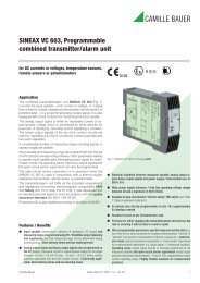
The purpose of the isolating amplifi er <strong>SINEAX</strong> <strong>TV</strong> <strong>808</strong> (Fig. 1) is<br />
to electrically insulate input and output signals, respectively to<br />
amplify and/or change the signal level or type (current or voltage)<br />
of the input signal.<br />
The instrument version <strong>SINEAX</strong> type <strong>808</strong>-1164 1A has an intrinsically<br />
safe output and FSK continuity function and is used to<br />
control smart I/P valve positioner in explosion hazard areas. The<br />
valve positioner adjust, for example, a pressure or the position of<br />
a valve in relation to the impressed output current (4…20 mA). The<br />
HART-bypass permits bi-directional FSK signals to pass according<br />
to the HART protocol.<br />
A green LED on the front side indicates device standing by.<br />
The power supply and the inputs and outputs are electrically<br />
insulated.<br />
The instrument fulfi ls all the important requirements and regulations<br />
concerning electromagnetic compatibility EMC and Safety (IEC<br />
1010 resp. EN 61 010). It was developed and is manufactured and<br />
tested in strict accordance with the quality assurance standard<br />
ISO 9001.<br />
Variants<br />
– and non-Ex isolating amplifi ers<br />
– Designed or not designed for FSK communication<br />
– User-specifi c input ranges<br />
– Power supply 24…60 V DC/AC or 85…230 V DC/AC<br />
Features / Benefi ts<br />
● Designed for FSK communication, hand-held terminal connected to<br />
separate terminals. This facilitates operation in conjunction with a<br />
smart I/P valve positioner designed for FSK and with a HART or userspecifi<br />
c protocol<br />
● Electric insulation between input, output 2.3 kV and power supply<br />
(3.7 kV) / Prevents measurement errors due to potential leakage<br />
● Burden voltage 20 V for non-Ex versions or 15 V for Ex instruments<br />
● Non-standard user-specifi c ranges available<br />
● AC/DC power supply / Universal<br />
<strong>Camille</strong> <strong>Bauer</strong> Data sheet <strong>TV</strong> <strong>808</strong>-115/6/7/8 Le – 12.08 1<br />
0102<br />
II (1) G<br />
Fig. 1. <strong>Isolating</strong> amplifi er <strong>SINEAX</strong> <strong>TV</strong> <strong>808</strong> in housing S17<br />
clipped onto a top-hat rail.<br />
● Available in type of protection “Intrinsic safety” [EEx ia] IIC<br />
(see “Table 3: Data on explosion protection”)<br />
Technical data<br />
Measuring input<br />
DC current: Standard range 4…20 mA<br />
Limit values 0…0.1 to 0…40 mA<br />
also live-zero,<br />
start value > 0 to ≤ 50% fi nal value<br />
– 0.1…0…+ 0.1 to<br />
– 20…0…+ 20 mA<br />
max. span ≤ 40 mA<br />
also bipolar asymmetrical<br />
R = 15 Ω<br />
i<br />
DC voltage: Limit values<br />
0…0.06 to 0…40, also live-zero,<br />
start value > 0 to ≤ 50% fi nal value<br />
– 0.06…0…+ 0.06 to<br />
– 20…0…+ 20 V,<br />
max. span ≤ 40 V<br />
R = 100 kΩ<br />
i<br />
1 FSK = Frequency Shift Keying
<strong>SINEAX</strong> <strong>TV</strong> <strong>808</strong>, 1 <strong>channel</strong><br />
<strong>Isolating</strong> Amplifi er, output Ex or non-Ex<br />
Overload capacity: DC current continuously 2-fold<br />
DC voltage continuously 2-fold<br />
Measuring output<br />
DC current: Standard ranges<br />
4…20 mA, 0…20 mA<br />
20…4 mA, 20…0 mA<br />
Burden voltage: Non-Ex version 20 V,<br />
Ex version 15 V<br />
External resistance: Non-Ex version 1000 Ω,<br />
Ex version 750 Ω<br />
Current limiter at<br />
R ext max.: Approx. 1.1 x I AN<br />
Voltage limiter at R ext = ∞: Approx. 26 V<br />
Residual ripple in<br />
output current: < 0.5% p.p.<br />
Response time: < 50 ms<br />
Power supply H<br />
AC/DC power pack (DC and 45...400 Hz)<br />
Table 1: Nominal voltages and tolerances<br />
Nominal voltage U N<br />
Tolerance<br />
24 … 60 V DC/AC DC – 15 … + 33%<br />
85 … 230 V AC ± 15%<br />
1 DC/AC<br />
24 … 60 V DC/AC<br />
85 … 230 V AC ± 10%<br />
DC – 15 … + 33%<br />
AC ± 15%<br />
85 … 110 V DC – 15 … + 10%<br />
Power input: ≤ 1.2 W resp. ≤ 3 VA<br />
Accuracy data (acc. to DIN/IEC 770)<br />
Instrument<br />
version<br />
Standard<br />
(Non-Ex)<br />
Type of<br />
protection<br />
“Intrinsically<br />
safe”<br />
[EEx ia] IIC<br />
Basic accuracy: Limit error ≤ ± 0.2%<br />
Including linearity and reproducibility<br />
errors<br />
Reference conditions:<br />
Ambient temperature 23 °C, ± 2 K<br />
Power supply 24 V DC ± 10% and<br />
230 V AC ± 10%<br />
Output burden Current: 0.5 · R ext max<br />
Infl uencing factors:<br />
Temperature < ± 0.1% per 10 K<br />
Burden infl uence < ± 0.1%<br />
Longtime drift < ± 0.3% / 12 months<br />
Switch-on drift < ± 0.2%<br />
Common and transverse<br />
mode infl uence < ± 0.2%<br />
Output + or –<br />
connected to ground < ± 0.2%<br />
Installation data<br />
Housing: Housing S17<br />
See section “Dimensional drawings”<br />
for dimensions<br />
Material of housing: Lexan 940 (polycarbonate)<br />
flammability class V-0 acc. to<br />
UL 94, self-extinguishing, nondripping,<br />
free of halogen<br />
Mounting: For snapping onto top-hat rail<br />
(35 ×15 mm or 35 × 7.5 mm) acc.<br />
to EN 50 022<br />
or<br />
directly onto a wall or panel using<br />
the pull-out screw hole brackets<br />
Position of use: Any<br />
Terminals: DIN/VDE 0609<br />
Screw terminals with wire guards,<br />
for light PVC wiring and<br />
max. 2 x 0.75 mm 2 or 1 x 2.5 mm 2<br />
Permissible vibrations: 2 g acc. to EN 60 068-2-6<br />
Shock: 3 x 50 g<br />
3 shocks each in 6 directions acc.<br />
to EN 60 068-2-27<br />
Weight: Approx. 0.19 kg<br />
Electric insulation: All circuits (measuring input / measuring<br />
output / power supply) are<br />
electrically insulated<br />
Regulations<br />
Electromagnetic<br />
compatibility: The standards DIN EN 50 081-2 and<br />
DIN EN 50 082-2 are observed<br />
Intrinsically safe: Acc. to EN 50 020: 1994<br />
1 For power supplies > 125 V, the auxiliary circuits should include an<br />
external fuse with a rating ≤ 20 A DC.<br />
2 Data sheet <strong>TV</strong> <strong>808</strong>-115/6/7/8 Le – 12.08 <strong>Camille</strong> <strong>Bauer</strong>
Protection (acc. to IEC 529<br />
resp. EN 60 529): Housing IP 40<br />
Connection IP 20<br />
Electrical standards: Acc. to IEC 1010 resp. EN 61 010<br />
Operating voltages: < 300 V between all insulated circuits<br />
Contamination level: 2<br />
Overvoltage category<br />
acc. to IEC 664: III for power supply<br />
II for measuring input and measuring<br />
output<br />
Double insulation: Power supply versus all other circuits<br />
Measuring input versus measuring<br />
output<br />
Test voltage: Measuring input versus:<br />
Measuring output<br />
2.3 kV, 50 Hz, 1 min.<br />
Power supply<br />
3.7 kV, 50 Hz, 1 min.<br />
Measuring output versus:<br />
Power supply<br />
3.7 kV, 50 Hz, 1 min.<br />
Environmental conditions<br />
Climatic rating: Climate class 3Z acc. to<br />
VDI/VDE 3540<br />
Commissioning<br />
temperature: – 10 to + 55 °C<br />
Operating temperature: – 25 to + 55 °C,<br />
Ex – 20 to + 55 °C<br />
Storage temperature: – 40 to + 70 °C<br />
Annual mean<br />
relative humidity: ≤ 75%<br />
Altitude: 2000 m max.<br />
Indoor use statement!<br />
Table 3: Data on explosion protection II (1) G<br />
Order Code<br />
Type of<br />
protection<br />
<strong>808</strong> - 1... [EEx ia] IIC<br />
<strong>SINEAX</strong> <strong>TV</strong> <strong>808</strong>, 1 <strong>channel</strong><br />
<strong>Isolating</strong> Amplifi er, output Ex or non-Ex<br />
Output Input/Power supply<br />
U o = 27.3 V<br />
I o = 99 mA<br />
P o = 675 mW<br />
IIC IIB<br />
Lo 4.1 mH 15 mH<br />
Co 82 nF 677 nF<br />
Table 2: Ordering Informations<br />
Description Marking<br />
1. Mechanical design<br />
Housing S17 for<br />
<strong>808</strong> - 1<br />
rail and wall mounting<br />
2. Number of <strong>channel</strong>s<br />
1 <strong>channel</strong> 1<br />
3. Version / Power supply<br />
[EEx ia] IIC, 24 … 60 V DC/AC<br />
5<br />
(output intrinsically safe)<br />
[EEx ia] IIC, 85 … 110 V DC / 230 V AC<br />
6<br />
(output intrinsically safe)<br />
Standard, 24 … 60 V DC/AC 7<br />
Standard, 85 … 230 V DC/AC 8<br />
4. Function<br />
1 input, 1 electrically insulated output 1<br />
1 input, 1 electrically insulated output, desig- 4<br />
ned for FSK communcation (HART)<br />
(Condition: Input and output 4 … 20 mA)<br />
5. Input signal<br />
4 … 20 mA 1<br />
Input [V] 9<br />
[V] 0 … 0.06 to 0 … 40, also live-zero,<br />
start value > 0 to ≤ 50% fi nal value<br />
[V] – 0.06 … 0 … + 0.06 to – 20 … 0 … + 20,<br />
max. span ≤ 40 V<br />
also bipolar asymmetrical<br />
Input [mA] Z<br />
[mA] 0 … 0.1 to 0 … 40, also live-zero,<br />
start value > 0 to ≤ 50% fi nal value<br />
[mA] – 0.1 … 0 … + 0.1 to – 20 … 0 … + 20<br />
max. span ≤ 40 mA<br />
also bipolar asymmetrical<br />
6. Output signal<br />
4 … 20 mA A<br />
0 … 20 mA B<br />
20 … 4 mA C<br />
20 … 0 mA<br />
With FSK communication (HART) only possible<br />
with 4 … 20 mA<br />
D<br />
Possible special versions, e.g. increased climatic rating on<br />
inquiry.<br />
U m = 253 V AC<br />
resp.<br />
125 V DC<br />
Type Examination<br />
Certifi cate<br />
PTB 97 ATEX 2191<br />
Mounting location<br />
Outside<br />
the hazardous<br />
area<br />
<strong>Camille</strong> <strong>Bauer</strong> Data sheet <strong>TV</strong> <strong>808</strong>-115/6/7/8 Le – 12.08 3
<strong>SINEAX</strong> <strong>TV</strong> <strong>808</strong>, 1 <strong>channel</strong><br />
<strong>Isolating</strong> Amplifi er, output Ex or non-Ex<br />
Compatibility<br />
Most of the usual smart valve positioners (current-to-pneumatic converter) on the market with IS approval are compatible with the<br />
intrinsically safe output of the <strong>TV</strong> <strong>808</strong> (see Table 4). On inquiry, we will verify if other valve positioners can be used.<br />
Table 4:<br />
Manufacturer Type Ex designation<br />
Neles<br />
Jamesbury<br />
Elsag Bailey-<br />
H & B<br />
ND820<br />
TZID<br />
Samson 3780<br />
Foxboro<br />
Eckhart<br />
Fisher<br />
Controls<br />
EEx ia IIC T5, T6<br />
Demko 96D, 120954<br />
EEx ia IIC T4, T5, T6<br />
PTB Nr. -94.C.2133 X<br />
EEx ia IIC T6<br />
PTB Nr. Ex-94.C.4069<br />
4 Data sheet <strong>TV</strong> <strong>808</strong>-115/6/7/8 Le – 12.08 <strong>Camille</strong> <strong>Bauer</strong><br />
U i<br />
[V]<br />
I i<br />
[mA]<br />
P i<br />
[mW]<br />
L i<br />
[mH]<br />
C i<br />
[nF]<br />
30 100 ––– 0 0<br />
30 150 1100 0.05 1.2<br />
28 115 1000 0 5.3<br />
SRD991 EEx ia IIC (T6) 30 130 900 0 1.4<br />
Fieldvue<br />
DVC 5000<br />
Siemens SIPART PS<br />
Electrical connections<br />
1 6<br />
2 7 12<br />
<strong>Camille</strong> <strong>Bauer</strong> <strong>AG</strong><br />
CH-5610 Wohlen<br />
Switzerland<br />
3 8 3 8<br />
4 9<br />
5 10<br />
Without<br />
transparent cover<br />
Front<br />
Without<br />
function<br />
1 6<br />
4 9<br />
E = Input<br />
HHT = Hand-Held-Terminal<br />
A = Output<br />
H = Power supply<br />
<strong>SINEAX</strong><br />
<strong>TV</strong> <strong>808</strong><br />
ON<br />
5 10<br />
EEx ia IIC T5<br />
LCIE 95.D6115<br />
With<br />
transparent cover<br />
EEx ib IIC T4, T5, T6<br />
PTB Nr. Ex-91, C, 2138<br />
Space e.g.<br />
for MSK designation<br />
ON<br />
Green LED for<br />
device standing by<br />
30 227 1700 0 0<br />
30 100 1000 1 6<br />
4 9<br />
–<br />
E<br />
+<br />
1 6<br />
–<br />
A<br />
+<br />
3 8<br />
–<br />
Burden voltage [V]<br />
Burden [Ω]<br />
HHT<br />
+<br />
5 10<br />
–<br />
H<br />
+<br />
12.6 V<br />
630 Ω<br />
10.8 V<br />
540 Ω<br />
10.8 V<br />
540 Ω<br />
12.0 V<br />
600 Ω<br />
12.0 V<br />
600 Ω<br />
11.0 V<br />
550 Ω
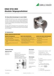
Table 5: Terminal allocation<br />
<strong>SINEAX</strong> <strong>TV</strong> <strong>808</strong>, 1 <strong>channel</strong><br />
<strong>Isolating</strong> Amplifi er, output Ex or non-Ex<br />
Instruments version Wiring diagram / Terminal allocation<br />
Types <strong>808</strong>-1154 1A<br />
or<br />
<strong>808</strong>-1164 1 A<br />
Input non-Ex,<br />
output intrinsically safe<br />
burden voltage 15 V,<br />
designed for FSK<br />
Fig. 2<br />
Types <strong>808</strong>-117. ..<br />
or<br />
<strong>808</strong>-118. ..<br />
Input and output non-Ex,<br />
burden voltage 20 V,<br />
FSK (option)<br />
Fig. 3<br />
1 HHT = Hand-Held-Terminal<br />
E<br />
E<br />
–<br />
+<br />
4…20 mA<br />
~ (–)<br />
H<br />
~ (+)<br />
–<br />
+<br />
–<br />
4…20 mA<br />
~ (–)<br />
H<br />
~ (+)<br />
1 6<br />
3<br />
4<br />
5<br />
Safe area<br />
<strong>Camille</strong> <strong>Bauer</strong> Data sheet <strong>TV</strong> <strong>808</strong>-115/6/7/8 Le – 12.08 5<br />
8<br />
9<br />
10<br />
1 6<br />
3<br />
4<br />
5<br />
8<br />
9<br />
10<br />
+<br />
Safe area<br />
A<br />
FSK<br />
FSK<br />
+ –<br />
4…20 mA<br />
–<br />
+<br />
+ –<br />
A<br />
Hazardous<br />
area<br />
X<br />
e.g. I/P-converter<br />
HHT 1<br />
HHT 1
<strong>SINEAX</strong> <strong>TV</strong> <strong>808</strong>, 1 <strong>channel</strong><br />
<strong>Isolating</strong> Amplifi er, output Ex or non-Ex<br />
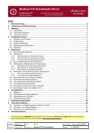
Dimensional drawings<br />
120<br />
17.5<br />
+0.5+<br />
0<br />
146.5<br />
Fig. 4. <strong>SINEAX</strong> <strong>TV</strong> <strong>808</strong> in housing S17 clipped onto a top-hat rail<br />
(35 ×15 mm or 35×7.5 mm, acc. to EN 50 022).<br />
Standard accessories<br />
1 Operating Instructions in three languages: German, French,<br />
English<br />
2 Labels (under transparent cover)<br />
1 Type Examination Certifi cate (for instruments in type of<br />
protection “Intrinsically safe” only)<br />
Subect to change without notice • Edition 12.08 • Data sheet <strong>TV</strong> <strong>808</strong>-115/6/7/8 Le<br />
120<br />
14<br />
134<br />
120<br />
17.5 +0.5+<br />
0<br />
6.5<br />
12<br />
Ø4.5<br />
Rely on us.<br />
145.5<br />
Fig. 5. <strong>SINEAX</strong> <strong>TV</strong> <strong>808</strong> in housing S17, screw hole mounting brackets<br />
pulled out.<br />
<strong>Camille</strong> <strong>Bauer</strong> Ltd<br />
Aargauerstrasse 7<br />
CH-5610 Wohlen / Switzerland<br />
Phone: +41 56 618 21 11<br />
Fax: +41 56 618 35 35<br />
e-mail: info@camillebauer.com<br />
www.camillebauer.com