A TUNE-UP FOR THE DUAL TURNTABLE - ThaiHDbox
A TUNE-UP FOR THE DUAL TURNTABLE - ThaiHDbox
A TUNE-UP FOR THE DUAL TURNTABLE - ThaiHDbox

You also want an ePaper? Increase the reach of your titles
YUMPU automatically turns print PDFs into web optimized ePapers that Google loves.
Reliable Reviews<br />
Oatley Electronics K272A Headphone Amp By Aren van Waarde<br />
Oatley Electronics (www.oatleyelectronics.<br />
com), which sells electronic parts and used<br />
equipment in New South Wales (Australia),<br />
has launched a small range of audio kits based<br />
on tube technology. My interest was raised<br />
by glowing reviews written by Mark Houston,<br />
DIY convener of the Melbourne Audio Club 1 .<br />
The kits employ subminiature valves (pentodes<br />
type 6418) made in the 1970s by the American<br />
company Raytheon for military purposes (use<br />
in cryptographic equipment) 2 . Such valves<br />
have also been employed by the Royal Dutch<br />
Navy, and as outdated navy stocks are sold by<br />
local dumpstores at rock-bottom prices, many<br />
6418s ended up in my junkbox. I intended to<br />
use these tubes for building a regenerative<br />
receiver, but never considered them for audio<br />
purposes until I discovered the Oatley products.<br />
Currently, the following vacuum tube kits<br />
are available: K261 Tube Preamplifier (single<br />
gain stage, for piezo transducer, e.g., of electric<br />
guitar, AUS $22), K270 Tube Preamplifier<br />
(like K261, but dual gain stage and volume<br />
control, AUS $29), K272A Stereo Tube Preamplifier/Headphone<br />
Driver (AUS $30), K281<br />
Tube-based 5/10W Power Amplifier (AUS<br />
$29), and K282 Tube-based Stereo RIAA<br />
Preamp (AUS $47). I ordered the K272A and<br />
the K282. The website allows secure ordering<br />
by credit card. Customers are treated courteously:<br />
by first confirming receipt of the order<br />
and receipt of payment and then sending<br />
the goods with package number. My kits arrived<br />
within two weeks. This article offers a<br />
description of the K272A, my experiences in<br />
wielding the soldering iron, and a subjective<br />
evaluation of the sonic results.<br />
K272A Circuit<br />
The schematic of the K272A is shown in Fig.<br />
1. As you will notice, the actual amplifier circuit<br />
is quite simple, but a few compounds<br />
have been added to provide DC power to the<br />
tube heaters and the output buffers.<br />
The gain stage of each stereo channel consists<br />
of a single 6418 wired in triode mode (V1<br />
and V2). Wired in this way, a 6418 will provide<br />
a voltage gain of about 7. Because the valves<br />
run at very low anode currents (between 10<br />
and 15�A!), they are not capable of driving<br />
headphones directly. The amplified signal at<br />
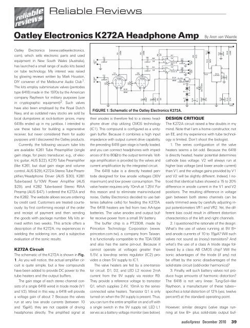
FIGURE 1: Schematic of the Oatley Electronics K272A.<br />
their anodes is therefore fed to a stereo headphone<br />
driver chip utilizing CMOS technology<br />
(IC1). This compound is configured as a unitygain<br />
buffer. Because it combines a high input<br />
impedance with output current drive capability,<br />
the preceding 6418 gain stage is hardly loaded,<br />
and you can connect headphones with impedances<br />
of 8 to 80� to the output terminals. Voltage<br />
amplification is provided by the valves and<br />
current amplification by the integrated circuit.<br />
The 6418 tube is a directly heated pentode<br />
designed for low anode voltages (30V<br />
maximum) and low power consumption. The<br />
valve heater requires only 10mA at 1.25V. For<br />
this reason and to eliminate mains-induced<br />
noise, Oatley Electronics decided to use batteries<br />
(alkaline cells) for feeding the K272A.<br />
The 6418 heaters are fed from two AA-type<br />
batteries. The valve anodes and output buffer<br />
receive power from a small 9V battery.<br />
The buffer chip is a PT2308, made by<br />
Princeton Technology Corporation (www.<br />
princeton.com.tw), a company from Taiwan.<br />
It is functionally compatible to the TDA1308<br />
and also has the same pin-out. Because it<br />
cannot operate at voltages greater than<br />
5.5V, a low-drop series regulator (IC2) provides<br />
a clean 5V supply to IC1.<br />
The valve heaters are fed by a one-transistor<br />
circuit. D1, D2, and LED L2 receive 2mA<br />
current from the 9V supply via resistor R9.<br />
They provide a reference voltage to transistor<br />
Q1, which supplies 2.4V, 10mA to the seriesconnected<br />
valve heaters. Transistor Q1 is only<br />
turned on when the 9V supply is present. Thus,<br />
you can turn the entire amplifier on and off with<br />
a single switch in the 9V supply rail. LED L1<br />
serves as a battery voltage monitor (see below).<br />
DESIGN CRITIQUE<br />
The K272A circuit raised a few doubts in my<br />
mind. Note that I am a home constructor, not<br />
an EE, and my experience with tube technology<br />
is limited. Don’t shoot the biologist.<br />
1. The series configuration of the valve<br />
heaters seems a bit odd. Because the 6418<br />
is directly heated, heater potential determines<br />
cathode bias voltage. V2 will always run at<br />
higher bias voltage (and lower anode current)<br />
than V1, and the voltage gains provided by V1<br />
and V2 will be slightly different. Indeed, I noticed<br />
that identical tubes showed a 15 to 20%<br />
difference in anode current in the V1 and V2<br />
positions. The resulting difference in voltage<br />
gain between both stereo channels can be<br />
easily trimmed away by carefully adjusting input<br />
potentiometers VR1 and VR2. Yet, the different<br />
bias could result in different distortion<br />
characteristics of the left and right channels.<br />
2. I questioned the rationale of the design.<br />
What’s the use of valves running at 9V B+<br />
and anode currents of 10 to 15�A? Will such<br />
valves not sound as (noisy) transistors? And<br />
what’s the use of a class A triode stage followed<br />
by a class AB CMOS chip? Will the<br />
sonic advantages of the triode (if any) not<br />
be offset by the sonic disadvantages of the<br />
solid-state circuit (odd-order harmonics)?<br />
3. Finally, will such battery valves not produce<br />
huge amounts of harmonic distortion?<br />
The 6418 is not very linear. Tung-Sol—like<br />
Raytheon, a manufacturer of these tubes—<br />
specifies a total distortion of 12% (yes, twelve<br />
percent!) at the standard operating point.<br />
However, similar designs (valve stage running<br />
at low B+ plus solid-state output buf-<br />
audioXpress December 2010 39