Tune-A-Cam Kit - Crane Cams
Tune-A-Cam Kit - Crane Cams
Tune-A-Cam Kit - Crane Cams

You also want an ePaper? Increase the reach of your titles
YUMPU automatically turns print PDFs into web optimized ePapers that Google loves.
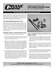
DEGREEING IN YOUR CAM<br />
The purpose of degreeing a cam is to insure that the<br />
cam is phased correctly with the crankshaft per the<br />
cam manufacturer's specifications. Some factors that<br />
may cause improper phasing are: <strong>Cam</strong> or crank gears<br />
incorrectly marked; keyways out of position on gears;<br />
or keyway in the crankshaft mis-indexed. It is the<br />
exception, rather than the rule, that a cam may be out<br />
of phase, but this factor should be known in order to be<br />
able to establish a baseline, or a point of tune. This kit<br />
will aid you in a complete engine reassembly or for just<br />
a check of the camshaft timing when the camshaft is<br />
replaced with the engine in the motorcycle. Refer to<br />
your service manual for any engine specifications or<br />
instructions necessary for proper assembly of your<br />
engine.<br />
EQUIPMENT IN YOUR KIT<br />
Included in your <strong>Tune</strong>-A-<strong>Cam</strong>-<strong>Kit</strong>:<br />
1. An accurate degree wheel for the crankshaft<br />
2. A pointer to be firmly attached to the engine to<br />
indicate points on the degree wheel.<br />
3. A dial indicator to accurately measure cam lift,<br />
end play and valve travel.<br />
4. Top dead center stop bolt.<br />
5. Checking springs to replace valve springs for<br />
checking valve clearances.<br />
6. Checking plug to replace stock hydraulic lifter<br />
plunger during dial indicator checks.<br />
ENGINE IN CHASSIS METHOD<br />
This is a quick check method to degree in your<br />
camshaft when the engine is in the chassis, and the<br />
primary drive side of crankshaft is not accessible for a<br />
degree wheel. The method uses a measurement<br />
taken at the lifter with the dial indicator. The measurement<br />
is from the heel of the cam to a point partially up<br />
4/00<br />
Installation Instructions<br />
<strong>Tune</strong>-A-<strong>Cam</strong> <strong>Kit</strong><br />
For “Big Twin” Harley-Davidson ®<br />
For more information, see www.cranecams.com<br />
1<br />
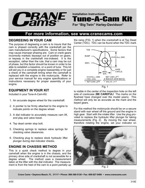
the ramp (FIG. 1) when the crankshaft is at Top Dead<br />
Center (TDC). TDC can be found when the TDC mark<br />
Fig. 1<br />
is visible in the center of the inspection hole on the left<br />
side of crankcase (BE CAREFUL! The marks on the<br />
flywheel have changed over the model years). This<br />
method will only be as accurate as the mark and the<br />
keyed gears.<br />
For this method the motorcycle should be on a secure<br />
stand with rear wheel off the ground and the engine in<br />
high gear. Start with the intake lifter. Use the plug provided<br />
to replace the hydraulic lifter plunger for taking<br />
measurements (Fig. 2). By moving the rear wheel,<br />
therefore rotating the engine, set your indicator on<br />
Fig. 2<br />
<strong>Crane</strong> <strong>Cam</strong>s • Daytona Beach, FL 31117 • Phone: 866-388-5120 • Fax: 608-627-0480 • www.cranecams.com<br />
310E
zero (0) when the lifter is riding on the heel of the cam<br />
(the lowest reading). Rotate your crankshaft forward<br />
until the indicator starts to move. Now watch for the<br />
TDC mark on the flywheel. When the mark is centered<br />
in the hole, read the dial indicator and write down the<br />
amount of travel. Turn the crankshaft back to where<br />
the lifter is on the heel again to double check your zero<br />
measurement. Compare with the figure on the specification<br />
card.<br />
Now check the exhaust lifter. The difference in exhaust<br />
measurement is that once you establish your "0" on<br />
the heel, you rotate the crankshaft backwards. When<br />
the indicator starts to move, watch for the TDC mark<br />
on the flywheel. When it is centered in the hole, take<br />
your reading. Double check it and compare with the<br />
specification card. Readings of +.005" or -.005" of the<br />
specification card will not have an adverse affect on<br />
tuning.<br />
ENGINE OUT OF CHASSIS METHOD<br />
The piston moves very little in relation to crankshaft<br />
rotation when it is near TDC, so it is practically impossible<br />
to find exact TDC with a dial indicator by rocking<br />
the crankshaft back and forth. The positive-stop<br />
method is the answer. Install the degree wheel so it<br />
can be read from the right side of the engine (Fig. 3).<br />
Rotate the crankshaft to get the front cylinder piston in<br />
approximate TDC position by looking through the<br />
spark plug hole. Next, adjust the degree wheel to TDC<br />
position in relation to the pointer. This is just a rough<br />
approximation, but it can save errors later. It is essential<br />
at this point that you have some means of rotating<br />
the crank that will not interfere with the degree wheel.<br />
No matter how tight it is, there is a definite chance of<br />
slight misalignment while forcing the crank around.<br />
After the degree wheel has been set approximately,<br />
and a means for turning the crank provided, you're<br />
ready to install and set the piston stop. This requires<br />
turning the crankshaft to lower the piston enough in<br />
4/00<br />
Fig. 3<br />
2<br />
the cylinder by moving the crankshaft 15-20 degrees.<br />
Screw in the piston stop until it touches the piston (Fig.<br />
4). Gently turn the engine in the same direction until<br />
Fig. 4<br />
the piston comes back up and touches the piston stop.<br />
Make a note of what degree the pointer is on. Rotate<br />
the engine in the opposite direction until the piston<br />
comes back up and touches the piston stop again.<br />
Make a note of what degree the pointer is on. Add<br />
these two numbers together then divide by two.<br />
Example: Let's say that the stop points are 16° in one<br />
direction and 20° in the opposite direction. The total<br />
would be 36 degrees. Divided in half would be 18<br />
degrees. Therefore, 18 degrees from either of your<br />
stop points is true Top Dead Center. Move the pointer<br />
to align with the 18 degree mark on the degree wheel,<br />
without moving the engine or degree wheel so the piston<br />
is still against the stop. Now turn the engine in the<br />
opposite direction until the piston comes back up and<br />
touches the stop. The pointer should be aligned with<br />
the 18 degree mark on the other side of the TDC mark.<br />
If this is correct, you have found positive top dead center.<br />
It is best to repeat this to make sure that nothing<br />
has moved.<br />
If you didn't get the same results both times, per our<br />
example, you will need to repeat the procedure until<br />
you get the same amount of degrees on both sides of<br />
TDC. Remove your piston stop and you are ready to<br />
properly degree your cam.<br />
It is important that the dial indicator's plunger be<br />
aligned as closely as possible with the lifter being<br />
measured. The lifter plug should be installed in the<br />
lifter. Any substantial angle between the axis of the<br />
plunger and the lifter will introduce geometrical errors<br />
in the lift reading (Fig. 5).<br />
When the degree wheel and its pointer are accurately<br />
set, and the dial indicator is solidly in place, rotate the<br />
crankshaft until the cam's base circle is under the lifter<br />
for the cam lobe being measured. Set the dial indica-<br />
310E
tor to zero at this point. Be sure the dial indicator is<br />
pre-loaded about .100" to insure that it will not run out<br />
of travel while on the base circle. Rotate the crankshaft<br />
to lift and lower the tappet several times to verify<br />
that the dial always returns to zero when the lifter is on<br />
the base circle. If it doesn't return to zero, there are<br />
several possible causes: (1) the dial indicator may not<br />
be mounted rigidly; (2) the lifter may not be contacting<br />
the base circle solidly; (3) the lifter could be sticking<br />
slightly in its bore. Find the trouble and correct it<br />
before proceeding.<br />
It may be necessary to apply slight finger pressure<br />
against the lifter when rotating the engine to insure its<br />
return to the base circle.<br />
CHECKING BASE CIRCLE RUNOUT<br />
This is a good time to check for runout of the cam's<br />
base circle. This is out-of roundness, or wobble, during<br />
rotation. If the cam lobe is concentric with the<br />
camshaft bearing journals there shouldn't be any<br />
appreciable runout. We try to hold base circle runout<br />
to less than .001" for optimum cam performance and<br />
ease of setting lash. If the runout on your cam measures<br />
to more than .002" we would suggest returning<br />
it to the manufacturer.<br />
If there is measurable base circle runout on your cam,<br />
adjust the dial indicator so the runout is divided equally<br />
on both sides of zero. This will give the minimum<br />
error for checking the cam's timing.<br />
CAM SPECIFICATION CARD<br />
All the information you need for checking the timing<br />
accuracy and phasing of a camshaft is provided on the<br />
specification card that you receive with your cam. This<br />
will include the opening and closing timing points and<br />
the amount of lift (at the lifter) at which the timing<br />
should be checked.<br />
4/00<br />
Fig. 5<br />
3<br />
There are two popular methods of checking cam phasing:<br />
(1) Using the opening and closing figures at tappet<br />
lift off the base circle of the cam; (2) Using the<br />
intake centerline method.<br />
When checking with either method, always turn the<br />
engine in the normal direction of rotation because of<br />
possible slack in the timing gear drive.<br />
Using the opening and closing at cam lift, obtained<br />
from the information on your cam specification card,<br />
turn the engine in the normal direction of rotation.<br />
Watch the dial indicator move up .053" from the base<br />
circle, then stop rotating the engine. Record the<br />
degree number the pointer is on. Then continue to<br />
rotate the engine in the same direction. Watching the<br />
dial indicator, it will change direction at maximum lobe<br />
lift. Record the cam lobe lift. Continue to rotate the<br />
engine in the same direction until you reach .053"<br />
before returning to the base circle. Record this degree<br />
number. Continue on to zero lift and verify that the dial<br />
indicator has returned to zero. The opening and closing<br />
figures should be within +1 or -1 degree of the card<br />
figures.<br />
If you have any type of problem, contact your cam<br />
manufacturer for more information.<br />
If the intake centerline method is going to be used, you<br />
must first understand the difference between intake<br />
and exhaust certerline and lobe centerline (which<br />
should be more understandably stated as lobe separation).<br />
Lobe centerline (or separation) is the distance<br />
in cam degrees between the maximum lift point (centerline)<br />
of the intake lobe and the maximum lift point<br />
(centerline) of the exhaust lobe. This separation is<br />
ground in the cam and can't be changed unless the<br />
cam is reground. Intake and exhaust centerline relates<br />
to the phasing of the cam to the crankshaft.<br />
To locate the intake or exhaust centerline you must<br />
find the maximum lift of that lobe. Similar to finding<br />
TDC you must use an arbitrary figure, this time in thousandths<br />
of an inch instead of degrees, say .050". With<br />
the dial indicator on the intake lifter, rotate the engine<br />
in the normal direction until you reach maximum lift.<br />
This is where the dial indicator changes direction. At<br />
this point set the dial indicator at zero. Back the<br />
engine up until the dial indicator reads .100". Turn the<br />
engine back in the normal direction of rotation until the<br />
dial indicator reads .050". At this point record the<br />
degree number the pointer is on. Continue to rotate in<br />
the normal direction of rotation until the dial indicator<br />
goes past zero to .050" on the other side of maximum<br />
lift. Record the degree number the pointer is on. Add<br />
the two degree numbers together and divide by two.<br />
310E
That number will be the location of<br />
the maximum lift of the intake lobe in<br />
relation to the crankshaft. As you<br />
can see, this method does not tell<br />
you anything about the cam, or how<br />
well it is made.<br />
If the cam card you are using does<br />
not state what the intake centerline<br />
is, don't assume any number on the<br />
specification card is the intake centerline.<br />
In most cases the lobe separation<br />
(lobe centerline) is not the<br />
same as the intake centerline.<br />
Another point about the intake centerline<br />
method is that most cams<br />
today are of a non-symmetrical<br />
design, which means that the opening<br />
side of the lobe is not a mirror<br />
image of the closing side. Therefore,<br />
the "as measured" centerline will not<br />
be correct.<br />
Once the cam is phased with the<br />
crank, per the manufacturer specs,<br />
then a baseline can be established.<br />
From that baseline of performance<br />
you can dial the cam exactly to your<br />
combination. The cam can be<br />
advanced or retarded from the card<br />
specs up to 4 degrees. Advancing<br />
the cam will move the power band<br />
down in the RPM range. Whatever<br />
you gain in bottom end power you will<br />
lose on the top. Retarding the cam<br />
will move the power band up in the<br />
RPM range. If 4 degrees is not<br />
enough, a different camshaft profile<br />
would be needed.<br />
4/00<br />
Fig. 6<br />
Fig. 7<br />
Fig. 8<br />
4<br />
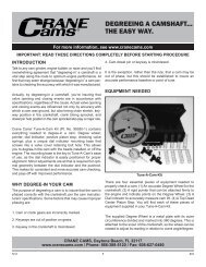
CHECKING<br />
CRANKSHAFT END PLAY<br />
Crankshaft end play is the maximum<br />
movement from side to side<br />
as pressure is applied to the ends<br />
of the crankshaft. Crankshaft end<br />
play should be checked at the time<br />
of assembly (Fig. 6).<br />
CHECKING CAMSHAFT<br />
END PLAY<br />
When your engine is reassembled<br />
or a camshaft is replaced, the<br />
camshaft end play must be<br />
checked (Fig. 7).<br />
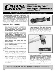
CHECKING VALVE<br />
COLLAR TO GUIDE<br />
TRAVEL<br />
A <strong>Tune</strong>-A-<strong>Cam</strong> <strong>Kit</strong> will check the<br />
distance a valve will travel from the<br />
fully closed position to the point the<br />
collar touches the valve guide. Set<br />
the dial indicator assembly up as<br />
shown in Fig. 8 with the kit's checking<br />
springs installed in place of<br />
valve springs. Set the dial indicator<br />
hand to zero and record the reading.<br />
Push the valve down (fully<br />
open position) and record that<br />
reading. Subtract the open reading<br />
from the closed reading and the difference<br />
will be the maximum possible<br />
valve travel. It is always best to<br />
allow .050" clearance from the collar<br />
to the guide at maximum lift to<br />
eliminate the possibility of contact<br />
during actual operation.<br />
310E