

Validation of turbine noise prediction tools with acoustic - MTU Aero ...
Validation of turbine noise prediction tools with acoustic - MTU Aero ...
Validation of turbine noise prediction tools with acoustic - MTU Aero ...

Create successful ePaper yourself
Turn your PDF publications into a flip-book with our unique Google optimized e-Paper software.
As can be seen, the microphones have been equally spaced in the axial direction and have been arranged<br />
in two lines to reduce the axial extent. Based on the assumption that the mean aerodynamic and aero<strong>acoustic</strong><br />
field are time-invariant for the duration <strong>of</strong> one test campaign, this setup using a traversable duct section<br />
permits the recording <strong>of</strong> the full circumference <strong>with</strong> a drastically reduced number <strong>of</strong> sensors. Finally, at the<br />
downstream end <strong>of</strong> the <strong>acoustic</strong> test section, the flow is redirected again into the vertical direction and leaves<br />
the laboratory through an exhaust stack at ambient conditions.<br />
Concerning the aerodynamic design, the LPT stage has been designed to represent the last stage <strong>of</strong> an<br />
LPT <strong>of</strong> a modern commercial aero engine at approximately half scale. With respect to the characteristic<br />
small expansion <strong>of</strong> the flow path at the rear stages <strong>of</strong> a typical engine, the cylindrical annular duct cross<br />
section motivated by <strong>acoustic</strong> reasons can be justified. Although designed for an aero design point (ADP), the<br />
rig has been operated at the three <strong>noise</strong> certification operating points (OP) approach, cutback, and sideline<br />
which are related to the ADP by the following factors (compare Table 2) to represent realistic operating<br />
conditions.<br />
Table 2. Rig operating points in relation to ADP [Ref. 2]<br />
parameter ADP Sideline Cutback Approach<br />
total pressure ratio [%] 100 97 85 73<br />
mass flow [%] 100 95 75 50<br />
shaft speed [%] 100 97 91 71<br />
shaft power [%] 100 87 48 16<br />
II.B. <strong>Aero</strong>dynamic and <strong>acoustic</strong> measurements<br />
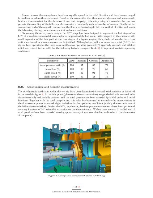
The aerodynamic conditions <strong>with</strong>in the test rig have been determined at several axial positions as indicated<br />
in the sketch in figure 4. In the inlet plane (plane 0) to the turbomachinery stage, the inflow is assumed to be<br />
circumferentially and radially uniform, and the total pressure has been recorded by a Kiel probe at 5 radial<br />
locations. Together <strong>with</strong> the total temperature, this value has been used to normalize the measurements in<br />
the downstream planes to cancel slight variations in the operating conditions (mainly due to variations <strong>of</strong><br />
the inflow characteristics). Behind the IGV, in plane A, five-hole probe measurements have been performed<br />
covering 4 sectors <strong>of</strong> 24 ◦ azimuthal extension on the circumference. Within these sectors, 21 radial and 17<br />
axial positions have been recorded starting approximately 4 mm from the duct walls (due to the dimensions<br />
<strong>of</strong> the probe).<br />
Figure 4. <strong>Aero</strong>dynamic measurement planes in STTF rig<br />
4 <strong>of</strong> 13<br />
American Institute <strong>of</strong> <strong>Aero</strong>nautics and Astronautics


![Download PDF [5,37 MB] - MTU Aero Engines](https://img.yumpu.com/21945461/1/190x125/download-pdf-537-mb-mtu-aero-engines.jpg?quality=85)