MXZ-2A52VA - Mitsubishi Electric Australia
MXZ-2A52VA - Mitsubishi Electric Australia
MXZ-2A52VA - Mitsubishi Electric Australia

You also want an ePaper? Increase the reach of your titles
YUMPU automatically turns print PDFs into web optimized ePapers that Google loves.
SPLIT-TYPE AIR CONDITIONER<br />
INSTALLATION MANUAL<br />
Model <strong>MXZ</strong>-<strong>2A52VA</strong><br />
HFC utilized<br />
R410A<br />
Refer to the installation manual of each indoor unit for indoor unit installation.<br />
FOR INSTALLER<br />
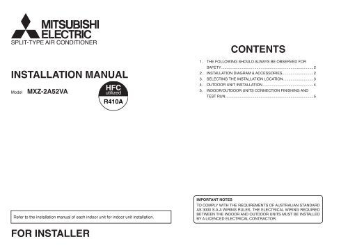
CONTENTS<br />
1. THE FOLLOWING SHOULD ALWAYS BE OBSERVED FOR<br />
SAFETY .........................................................................................2<br />
2. INSTALLATION DIAGRAM & ACCESSORIES ..............................2<br />
3. SELECTING THE INSTALLATION LOCATION .............................3<br />
4. OUTDOOR UNIT INSTALLATION .................................................4<br />
5. INDOOR/OUTDOOR UNITS CONNECTION FINISHING AND<br />
TEST RUN .....................................................................................5<br />
IMPORTANT NOTES<br />
TO COMPLY WITH THE REQUIREMENTS OF AUSTRALIAN STANDARD<br />
AS 3000 S.A.A WIRING RULES, THE ELECTRICAL WIRING REQUIRED<br />
BETWEEN THE INDOOR AND OUTDOOR UNITS MUST BE INSTALLED<br />
BY A LICENCED ELECTRICAL CONTRACTOR.
1. THE FOLLOWING SHOULD ALWAYS BE OBSERVED FOR<br />
SAFETY<br />
● Be sure to read “THE FOLLOWING SHOULD ALWAYS BE OBSERVED FOR SAFETY” before installing<br />
the air conditioner.<br />
● Be sure to observe the cautions specifi ed here as they include important items related to safety.<br />
● The indications and meanings are as follows.<br />
WARNING: Could lead to death, serious injury, etc.<br />
CAUTION: Could lead to serious injury in particular environments when operated incorrectly.<br />
● After reading this manual, be sure to keep it together with the OPERATING INSTRUCTIONS in a<br />
handy place on the customer’s site.<br />
■ Do not install the unit by yourself (customer).<br />
Incomplete installation could cause injury due to fi re,<br />
electric shock, the unit falling or leakage of water.<br />
Consult the dealer from whom you purchased the<br />
unit or special installer.<br />
■ Install the unit securely in a place which can bear<br />
the weight of the unit.<br />
When installed in an insuffi cient strong place, the unit<br />
could fall causing injury.<br />
■ Use the specifi ed wires to connect the indoor<br />
and outdoor units securely and attach the wires<br />
fi rmly to the terminal block connecting sections<br />
so the stress of the wires is not applied to the<br />
sections.<br />
Incomplete connecting and fi xing could cause fi re.<br />
■ Do not use intermediate connection of the power<br />
cord or the extension cord and do not connect<br />
many devices to one AC outlet.<br />
It could cause a fi re or an electric shock due to defective<br />
contact, defective insulation, exceeding the<br />
permissible current, etc.<br />
■ Check that the refrigerant gas due not leak after<br />
installation has completed.<br />
If refrigerant gas leaks indoors, and comes into contact<br />
with the fi re of a fan heater, space heater, stove,<br />
etc., harmful substances will be generated.<br />
■ Perform the installation securely referring to the<br />
installation manual.<br />
Incomplete installation could cause a personal injury<br />
due to fi re, electric shock, the unit falling or leakage<br />
of water.<br />
■ Perform earthing.<br />
Do not connect the earth wire to a gas pipe, water<br />
pipe, lightning rod or telephone earth wire. Defective<br />
earthing could cause an electric shock.<br />
■ Do not install the unit in a place where an infl ammable<br />
gas leaks.<br />
If gas leak and accumulate in the area surrounding<br />
the unit, it could cause an explosion.<br />
■ Fasten a fl are nut with a torque wrench as specifi<br />
ed in this manual.<br />
When fastened too tight, a fl are nut may broken after<br />
a long period and cause a leakage of refrigerant.<br />
WARNING<br />
■ Perform electrical work according to the installation<br />
manual and be sure to use an exclusive<br />
circuit.<br />
If the capacity of the power circuit is insuffi cient or<br />
there is insuffi cient electrical work, it could result in a<br />
fi re or an electric shock.<br />
■ Attach the electrical cover to the indoor unit and<br />
the service panel to the outdoor unit securely.<br />
If the electrical cover in the indoor unit and/or the<br />
service panel in the outdoor unit are not attached securely,<br />
it could result in a fi re or an electric shock due<br />
to dust water, etc.<br />
■ Be sure to use the part provided or specifi ed<br />
parts for the installation work.<br />
The use of defective parts could cause an injury due<br />
to a fi re, an electric shock, the unit falling, leakage of<br />
water, etc.<br />
■ Be sure to cut off the main power in case of setting<br />
up the indoor electronic control P.C. board<br />
or wiring works.<br />
It could cause an electric shock.<br />
■ The appliance shall be installed in accordance<br />
with national wiring regulations.<br />
■ When installing or relocating the unit, make sure<br />
that no substance other than the specifi ed refrigerant<br />
(R410A) enters the refrigerant circuit.<br />
Any presence of foreign substance such as air can<br />
cause abnormal pressure rise or an explosion.<br />
CAUTION<br />
■ Install an earth leakage breaker depending on the<br />
installation place (Where it is humid).<br />
If a earth leakage breaker is not installed, it could<br />
cause an electric shock.<br />
■ Perform the drainage/piping work securely according<br />
to the installation manual.<br />
If there is a defect in the drainage/piping work, water<br />
could drop from the unit and household goods could<br />
be wet and damaged.<br />
2<br />
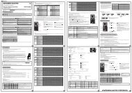
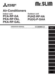
2. INSTALLATION DIAGRAM & ACCESSORIES<br />
Before installation<br />
This installation manual is only for the outdoor unit installation. In installing the indoor units, refer to the<br />
installation manual attached to each indoor unit.<br />
Any structural alternations necessary for the installation must comply with the local building code<br />
requirements.<br />
More than 100 mm<br />
Open as a rule<br />
More than 500 mm if<br />
the back, both sides<br />
and top are open<br />
Open as a rule<br />
More than 500 mm<br />
if the front and both<br />
sides are open<br />
K D<br />
More than 350 mm<br />
More than 100 mm<br />
More than 200 mm if<br />
there are obstacles to<br />
both sides<br />
Note:<br />
The dimensions given along the arrows above are required to guarantee<br />
the air conditioner’s performance. Install the unit in as wide a place as<br />
possible for later service or repairs.<br />
H<br />
C<br />
E<br />
J<br />
I<br />
F
Parts to be locally procured<br />
A<br />
B<br />
Power supply cord<br />
(3-core 2.5 mm2 )<br />
Indoor/outdoor unit connecting wire<br />
(4-core 1.0 mm2 /1.5 mm2 )<br />
C Extension pipe According to “Selecting pipe size” 1<br />
D Wall hole cover 1<br />
E Piping tape 1<br />
F<br />
Extension drain hose<br />
(or soft vinyl chloride hose of 15 mm in internal dia.<br />
or hard vinyl chloride pipe VP16)<br />
G Refrigeration oil Little amount<br />
H Putty 1<br />
I<br />
J<br />
Pipe fi xing band<br />
(The number depends on the pipe length.)<br />
Fixing screw for I<br />
(The number depends on the pipe length.)<br />
1<br />
1<br />
1<br />
2 to 7<br />
2 to 7<br />
K Wall hole sleeve 1<br />
L<br />
NOTE:<br />
Soft vinyl chloride hose of 25 mm in internal dia. or<br />
hard vinyl chloride pipe VP25<br />
● Do not use the drain socket and the drain cap in the cold region.<br />
Drain may freeze and it makes the fan stop.<br />
● The “Q’ty” for B to K in the above table is the quantity to be used per indoor unit.<br />
WARNING:<br />
Be sure to use specifi ed accessories and supplied parts for installation work. If there is some defi -<br />
ciency in parts, it may cause a risk of fi re, electric shock, injury by a unit fall or water leakage.<br />
Constraints On Indoor Unit Installation<br />
You should note that indoor unit that can be connected to this outdoor unit have the following constraints<br />
on them.<br />
● Indoor units with model numbers 22, 25 and 35 can be connected. Refer to the table below for possible<br />
indoor unit combinations.<br />
<strong>MXZ</strong>-<strong>2A52VA</strong> Combination<br />
2 UNIT 22+22 22+25 22+35 25+25 25+35 35+35<br />
1<br />
3<br />
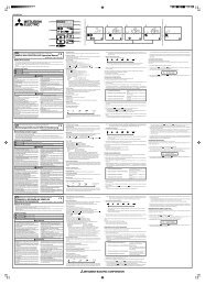
3. SELECTING THE INSTALLATION LOCATION<br />
● Where it is not exposed to strong wind.<br />
● Where airfl ow is good and dustless.<br />
● Where it is not exposed to rain and direct sunshine.<br />
● Where neighbours are not annoyed by operation sound or hot air.<br />
● Where rigid wall or support is available to prevent the increase of operation sound or vibration.<br />
● Where there is no risk of combustible gas leakage.<br />
● When installing the unit at a high level, be sure to fi x the unit legs.<br />
● Where it is at least 3 m away from the antenna of TV set or radio. Operation of the air conditioner may<br />
interfere with radio or TV reception in areas where reception is weak. An amplifi er may be required for the<br />
affected device.<br />
● Install the unit horizontally.<br />
● Please install it in an area not affected by snowfall or blowing snow. In areas with heavy snow, please install<br />
a canopy, a pedestal and/or some baffl e boards.<br />
Note:<br />
It is advisable to make a piping loop near outdoor unit so as to reduce vibration transmitted from<br />
there.<br />
WARNING:<br />
Be sure to install the unit in a place that well sustains its weight.<br />
Installing in a place with less strength may result in a unit falling, causing a risk of injury.<br />
CAUTION:<br />
Avoid the following places for installation where air conditioner trouble is liable to occur.<br />
● Where fl ammable gas could leak.<br />
● Where there is much machine oil.<br />
● Salty places such as the seaside.<br />
● Where sulfi de gas is generated such as<br />
a hot spring.<br />
● Where there is high-frequency or wireless<br />
equipment.<br />
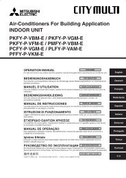
285<br />
17.5<br />
304~325<br />
344.5<br />
Note:<br />
When operating the air conditioner in low outside temperature, be sure to follow the instructions described<br />
below.<br />
● Never install the outdoor unit in a place where its air inlet/outlet side may be exposed directly to<br />
wind.<br />
● To prevent exposure to wind, install the outdoor unit with its air inlet side facing the wall.<br />
● To prevent exposure to wind, it is recommended to install a baffl e board on the air outlet side of the<br />
outdoor unit.<br />
Air in<br />
150<br />
500<br />
Air<br />
in<br />
Air<br />
out<br />
800<br />
4-10 x 21 Oval holes<br />
(Unit mm)
4. OUTDOOR UNIT INSTALLATION<br />
4-1 INSTALLING THE UNIT<br />
● Be sure to fi x the unit’s legs with bolts when installing it.<br />
● Be sure to install the unit fi rmly to ensure that it does not fall by an earthquake or a gust.<br />
● Refer to the fi gure in the right for concrete foundation.<br />
4-2 MOUNTING ARRANGEMENT OF DRAIN SOCKET<br />
Please perform the drain piping work only when draining from one place.<br />
CAUTION:<br />
Do not use drain socket and drain cap in the cold region.<br />
Drain may freeze and it makes the fan stop.<br />
1 Please choose one hole to discharge drain and install the drain socket to the hole.<br />
2 Please close the rest of the holes with the drain caps.<br />
3 Please connect a vinyl hose of 25 mm in the inside diameter on the market with the drain socket and lead<br />
drain.<br />
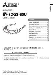
4-3 INDOOR/OUTDOOR WIRE CONNECTION AND OUTDOOR POWER SUPPLY<br />
CORD CONNECTION<br />
● Be sure to lead in the power supply cord A to the air conditioner in accordance with the specifi cation table<br />
below and “Technical Standards for <strong>Electric</strong>al Installation”.<br />
● Be sure to use special circuits for room air conditioner.<br />
CAUTION:<br />
Attach an earth leakage breaker according to your installation location. If any breaker is not attached,<br />
it may cause a risk of electric shock.<br />
WARNING:<br />
Be sure to comply with “Technical Standards for <strong>Electric</strong>al Installation”, follow this manual and use<br />
special circuits for electrical work. If there is a lack of circuit capacity or some defi ciency in installation,<br />
it may cause a risk of fi re or electric shock.<br />
Overcurrent that might be produced may include DC substances. Be careful to choose the correct type<br />
of overcurrent protection switch.<br />
Rated Voltage Breaker capacity Connect to the supply terminals and leave a contact separation of<br />
at least 3 mm at each pole to disconnect the source power pole.<br />
230 V 15A (When the power switch is shut off, it must disconnect all poles.)<br />
● Peel off both ends of the cables as shown in the right.<br />
● Take care not to let the cables contact the pipes inside the unit.<br />
● Take enough care to connect the indoor/outdoor unit connecting wire correctly between<br />
the respective indoor units and the outdoor unit.<br />
● Make earth wire a little longer than the others. (more than 35 mm)<br />
15 mm<br />
35 mm<br />
● For the power supply cord and the indoor/outdoor unit connecting wires, be sure to use the ones in compliance<br />
with the standards.<br />
● Be sure to push the core until it is hidden and pull each cable to make sure that it is not pulled up. Incomplete<br />
insertion may cause a risk of burning the terminal blocks.<br />
Power supply cord Specifi cation Cable 3-core 2.5 mm2 , in conformity with Design 245 IEC 57.<br />
Indoor and Outdoor connecting wire Specifi cation Cable 4-core 1.0/1.5 mm2 , in conformity with Design 245 IEC 57.<br />
This installation manual is only for the outdoor unit installation. In installing the indoor units, refer to the<br />
installation manual attached to each indoor unit.<br />
Indoor/outdoor unit connecting wire<br />
UNIT<br />
UNIT<br />
}<br />
}<br />
<br />
POWER SUPPLY LY L<br />
~/N 230 V 50 Hz<br />
1 Remove the service panel.<br />
2 Connect the indoor/outdoor wire and power supply cable to the terminal block.<br />
Be sure that the indoor/outdoor unit<br />
connecting wire B does not contact<br />
the stop valve.<br />
Firmly tighten the indoor/outdoor unit connecting<br />
wire B and the power supply cord A.<br />
B unit<br />
A unit<br />
Route the indoor/outdoor unit connecting wire<br />
B and the power supply cord A along with the<br />
unit.<br />
Cable clamp<br />
Power supply cord A<br />
WARNING:<br />
● Be sure to attach the service panel of the outdoor unit securely, otherwise it may result in a fi re or an<br />
electric shock from dust or water.<br />
● Use the indoor/outdoor unit connecting wire that meets the Standards to connect the indoor and<br />
outdoor units and fi x the wire to the terminal block securely so that no external force is conveyed to<br />
the connecting section of the terminal block. Incomplete connection or fi xing of the wire could result<br />
in a fi re.<br />
● Be sure to attach the terminal block cover on the both indoor and outdoor units. If the terminal block<br />
cover is incorrectly attached, it may cause a risk of fi re or electric shock due to dust or water penetration.<br />
4
5. INDOOR/OUTDOOR UNITS CONNECTION FINISHING AND TEST RUN<br />
5-1 FLARED CONNECTIONS<br />
PIPE LENGTH AND HEIGHT DIFFERENCE<br />
Limits <strong>2A52VA</strong><br />
Pipe length per indoor unit 20 m max.<br />
Total pipe length for multi-system 30 m max.<br />
Height difference* 15 m max.<br />
No. of bends per indoor unit 20 max.<br />
Total No. of bends for multi-system 30 max.<br />
* If the outdoor unit is installed higher than the indoor unit, max. height difference is reduced to 10 m.<br />
Refrigerant adjustment ....... If pipe length exceeds 20 m, additional refrigerant (R410A) charge is required.<br />
(The outdoor unit is charged with refrigerant for total pipe length up to 20 m.)<br />
Up to 20 m No additional charge is required.<br />
Pipe length<br />
Exceeding 20 m<br />
Additional charge is required.<br />
(Refer to the table below.)<br />
Refrigerant to be added 20 g/m × (refrigerant piping length(m)-20)<br />
Indoor unit B<br />
UNIT<br />
Indoor unit AUNIT<br />
● For pipe size, see the table below.<br />
SELECTING PIPE SIZE<br />
The diameter of connection pipes differs according to the type and capacity of indoor units. Match the diameters<br />
of connection pipes for indoor and outdoor units according to the following table.<br />
Model<br />
name<br />
22<br />
25<br />
35<br />
<strong>MXZ</strong>-<strong>2A52VA</strong><br />
A UNIT<br />
B UNIT<br />
Pipe size for indoor unit<br />
Allowable<br />
connection<br />
pipe size<br />
Liquid pipe ø6.35 mm ø6.35 mm<br />
Gas pipe ø9.52 mm ø9.52 mm<br />
Valve size for outdoor unit<br />
Liquid pipe ø6.35 mm<br />
Gas pipe ø9.52 mm<br />
Liquid pipe ø6.35 mm<br />
Gas pipe ø9.52 mm<br />
Outdoor<br />
unit<br />
5<br />
PIPING PREPARATION<br />
1 If you use commercially available copper pipes, use the following table for pipe specifi cations.<br />
Outside diameter Wall thickness<br />
Liquid pipe ø6.35 mm 0.8 mm<br />
Gas pipe ø9.52 mm 0.8 mm<br />
2 For insulation material, use 8 mm-thick heat-insulating expended polyethylene with a specifi c gravity of<br />
0.045.<br />
3 Ensure that the 2 refrigerant pipes are insulated to prevent condensation.<br />
4 Refrigerant pipe bending radius must be 100 mm or more.<br />
CAUTION:<br />
Be sure to use the insulation of specifi ed thickness. Excessive thickness may cause incorrect installation<br />
of the indoor unit and lack of thickness may cause dew drippage.<br />
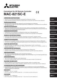
5-2 FLARING WORK<br />
● Main cause of gas leakage is defect in fl aring work.<br />
Perform fl aring work correctly in the following procedure.<br />
1. Pipe cutting<br />
● Cut the copper pipe correctly with pipe cutter.<br />
2. Burrs removal<br />
● Completely remove all burrs from the cut cross<br />
section of the pipe.<br />
● Put the end of the copper pipe downward to prevent<br />
burrs from dropping in the pipe.<br />
3. Putting nut on<br />
● Remove fl are nuts attached to indoor and outdoor<br />
units, then put them on pipe having completed<br />
burr removal. (not possible to put them on after<br />
fl aring work)<br />
● Flare nut for R410A pipe may differ from R22 pipe<br />
depending on the diameter of pipe.<br />
Copper<br />
pipe<br />
Burr<br />
Good<br />
90<br />
Flare nut<br />
Copper pipe<br />
No good<br />
Tilted Uneven Burred<br />
Spare<br />
reamer<br />
Pipe cutter<br />
Copper pipe
4. Flaring work<br />
● Perform fl aring work using fl aring tool as shown in the<br />
right.<br />
Outside<br />
diameter Flare tool for<br />
R410A clutch type<br />
A (mm)<br />
Conventional fl are tool<br />
Clutch type Wing nut type<br />
ø6.35 mm 0 to 0.5 1.0 to 1.5 1.5 to 2.0<br />
ø9.52 mm 0 to 0.5 1.0 to 1.5 1.5 to 2.0<br />
Firmly hold copper pipe in a die in the dimension shown in<br />
the table above.<br />
5. Check<br />
● Compare the fl ared work with the fi gure below.<br />
● Smooth all around<br />
If fl are is noted to be defective, cut off the fl ared section<br />
and perform fl aring work again.<br />
5-3 PIPE CONNECTION<br />
Note:<br />
Fasten a fl are nut with a torque wrench as specifi ed in the table below.<br />
When fastened too tight, a fl are nut may be broken after a long period and cause a leakage of refrigerant.<br />
1. Indoor unit connection<br />
● Connect both liquid pipe and gas pipe to indoor unit.<br />
- Apply a thin coat of refrigeration oil to the seat surface of pipe.<br />
- For connection, align the center of both pipe and union, then tighten the fi rst 3 to 4 turns in fl are nut by<br />
hand.<br />
- For tightening the union part of the indoor unit side, use the table below as a standard and tighten the<br />
fl are nut with two wrenches. Excessive tightening damages the fl ared section.<br />
Pipe diameter<br />
N·m<br />
Tightening torque<br />
kgf·cm<br />
ø6.35 mm 13.7 to 17.7 140 to 180<br />
ø9.52 mm 34.3 to 41.2 350 to 420<br />
Even length<br />
all around<br />
Flaring tool<br />
Die<br />
Copper pipe<br />
Clutch type<br />
A<br />
Flare nut<br />
Wing nut type<br />
2. Outdoor unit connection<br />
● Connect pipes to the pipe joint part of the stop valve in the same method as the indoor unit.<br />
- For tightening, use the same tightening torque applied for indoor unit and tighten the fl are nut with<br />
torque wrench or spanner.<br />
INSULATION AND TAPING<br />
1 Cover piping joints with pipe cover.<br />
2 For outdoor unit side, surely insulate every piping including valves.<br />
3 Using piping tape E, apply taping starting from the entry of outdoor unit.<br />
● Fix the end of piping tape E with adhesive tape.<br />
● When piping has to be arranged through above ceiling, closet or area where the temperature and humidity<br />
are high, wind additional commercially sold insulation for prevention of condensation.<br />
Yo r k<br />
Die<br />
Copper pipe<br />
Inside is shining without any scratches<br />
6<br />
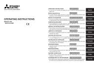
5-4 PURGING PROCEDURES • LEAK TEST<br />
● Perform the manifold valve work securely according to the installation manual of the manifold valve.<br />
PURGING PROCEDURES<br />
Connect the refrigerant pipes (both liquid pipe and gas pipe) between the indoor and the outdoor<br />
unit.<br />
Remove the service port cap of the stop valve on the gas pipe side of the outdoor unit. (The stop<br />
valve will not work in it initial state fresh out of the factory [totally closed with cap on].)<br />
Connect the gauge manifold valve and the vacuum pump to the service port of the stop valve on the<br />
gas pipe side of the outdoor unit.<br />
Run the vacuum pump. (Vacuumize for more than 15 minutes.)<br />
Check the vacuum with the gauge manifold valve, then close the gauge manifold valve and stop<br />
the vacuum pump.<br />
Leave it as is for one or two minutes. Make sure the pointer of the gauge manifold valve remains in<br />
the same position. Confi rm that the pressure gauge shows –0.101 MPa [Gauge] (–760 mmHg).<br />
*Perform the purging procedures<br />
on both A unit and B unit sides.<br />
Charge hose (for R410A)<br />
Stop valve<br />
(gas side)<br />
Service port<br />
-0.101MPa<br />
(-760 mmHg)<br />
Handle<br />
Low<br />
Compound pressure<br />
gauge (for R410A)<br />
Window<br />
Adapter for<br />
preventing<br />
the back flow<br />
Pressure gauge<br />
(for R410A)<br />
Gauge manifold<br />
valve (for R410A)<br />
Vacuum<br />
pump<br />
Handle High<br />
Charge hose<br />
(for R410A)<br />
Remove the gauge manifold valve quickly from the service port of the stop valve.<br />
(or the vacuum<br />
pump with the<br />
function to prevent<br />
the back flow)<br />
After refrigerant pipes are connected and evacuated, fully open all stop valves on both sides of gas<br />
pipe and liquid pipe.<br />
Operating without fully opening lowers the performance and this causes trouble.<br />
Pipe length up to 20 m<br />
No gas charge is needed.<br />
Pipe length exceeding 20 m<br />
Charge the prescribed<br />
amount of gas. (refer to 5-1)<br />
Tighten the cap to the service port to obtain the initial status.<br />
Retighten the cap.<br />
Leak test
WARNING:<br />
When installing or moving the unit, do not mix anything other than specifi ed refrigerant (R410A) into<br />
the refrigerating cycle.<br />
If air is mixed, it may cause the refrigerating cycle to get abnormally high temperature, causing a risk<br />
of burst.<br />
N·m<br />
Tightening torque<br />
kgf·cm<br />
Cap for service port 13.7 to 17.7 140 to 180<br />
Cap for stop valve 19.6 to 29.4 200 to 300<br />
5-5 EARTHING WORK<br />
Put the earth circuit to the ground in accordance with “Technical Standards for <strong>Electric</strong>al Installation”.<br />
CAUTION:<br />
Do not connect the earth cable to any gas pipe, water pipe, lightening rod or telephone earth cable.<br />
If there is some defi ciency in earthing work, it may cause a risk of electric shock.<br />
The product incorporates a frequency inverter and so requires earthing in order to observe electric charge and<br />
noise caused by static electricity.<br />
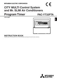
5-6 LOCKING THE OPERATION MODE OF THE AIR CONDITIONER (COOL, DRY,<br />
HEAT)<br />
● Description of the function:<br />
With this function, you can lock the operation mode<br />
of the outdoor unit. Once the operation mode is<br />
locked to either COOL/DRY mode or HEAT mode,<br />
the air conditioner operates in that mode only.<br />
● Initial setting is required to activate this function.<br />
Please explain about this function to your customers<br />
and ask them whether they want to use it.<br />
[How to lock the operation mode]<br />
1 Be sure to turn off the main power for the air conditioner<br />
before making the setting.<br />
2 Set the 2nd Dip Switch of SW1 on the outdoor controller<br />
board to ON to enable this function.<br />
3 To lock the operation mode in COOL/DRY mode, set<br />
the 1st Dip Switch of SW1 on the outdoor controller<br />
board to OFF. To lock the operation in HEAT mode,<br />
set the same switch to ON.<br />
4 Turn on the main power for the air conditioner.<br />
ON<br />
ON ON<br />
COOL/DRY HEAT AT A<br />
7<br />
5-7 LOWERING THE OPERATING NOISE OF THE OUTDOOR UNIT<br />
● Description of the function:<br />
With this function, you can lower the operating<br />
noise of the outdoor unit when the operation load is<br />
small, for example, during nighttime in COOL mode.<br />
However, please note that the cooling and heating<br />
capacity can also be lowered if this function is activated.<br />
* Initial setting is required to activate this function.<br />
Please explain about this function to your customers<br />
and ask them whether they want to use it.<br />
[How to lower the operating noise]<br />
1 Be sure to turn off the main power for the air conditioner<br />
before making the setting.<br />
2 Set the 3rd Dip Switch of SW1 on the outdoor controller<br />
board to ON to enable this function.<br />
3 Turn on the main power for the air conditioner.<br />
5-8 CHECKING AFTER INSTALLATION<br />
ON<br />
ON<br />
Lower the operating<br />
noise<br />
After fi nishing the installation, check the following items again by marking c.<br />
c Have special circuits been provided?<br />
c Is power supply voltage as specifi ed?<br />
c Has indoor/outdoor connecting wire been inserted into terminal block?<br />
c Has indoor/outdoor connecting wire been secured fi rmly?<br />
c Has intermediary connection between power cable and indoor/outdoor connecting wire been carried out?<br />
c Is combination of connection pipes and indoor/outdoor connecting wire correct (Room A, Room B)?<br />
c Is earth cable connection correct?<br />
c Has leak test been carried out?<br />
c Has air purge been carried out?<br />
c Is stop valve fully open?<br />
c Has drain discharge been checked?<br />
c Is insulation over connection pipe joints correct?<br />
c Is strength of installation location well enough?<br />
c Have all of WARNING and CAUTION items in “1. THE FOLLOWING SHOULD ALWAYS BE OB-<br />
SERVED FOR SAFETY” been checked?<br />
5-9 GAS CHARGE<br />
Perform gas charge to unit.<br />
1 Connect gas cylinder to the service port of stop valve.<br />
2 Perform air purge of the pipe (or hose) coming from refrigerant gas cylinder.<br />
3 Replenish specifi ed amount of the refrigerant, while operating the air conditioner for cooling.<br />
Note:<br />
In case of adding refrigerant, comply with the quantity specifi ed for the refrigerating cycle.
CAUTION:<br />
When charging the refrigerant system with additional refrigerant, be sure to use liquid refrigerant.<br />
Adding gas refrigerant may change the composition of the refrigerant in the system and affect normal<br />
operation of the air conditioner. Also, charge the system slowly, otherwise the compressor will be<br />
locked.<br />
To maintain the high pressure of the gas cylinder, warm the gas cylinder with warm water (under 40°C) during<br />
cold season. But never use naked fi re or steam.<br />
5-10 TEST RUN<br />
R<br />
c<br />
o<br />
(<br />
Union<br />
refrigerant charging<br />
● Be sure to perform the test run for each unit. Make sure each indoor unit operates properly following the<br />
installation manual attached to the unit.<br />
● If you perform the test run for all indoor units at once, you cannot detect any erroneous connection, if any, of<br />
the refrigerant pipes and the indoor/outdoor unit connecting wires.<br />
About the restart protective mechanism<br />
Once the compressor stops, the restart preventive device operates so the compressor will not operate for 3<br />
minutes to protect the air conditioner.<br />
5-11 EXPLANATION TO THE CUSTOMER<br />
● Recommend the customer to read the OPERATING INSTRUCTIONS carefully.<br />
● Using the OPERATING INSTRUCTIONS for each unit, explain the following to the customer, how to control<br />
temperature, how to remove the air fi lters, how to remove or put the remote controller in the remote controller<br />
holder, how to clean, precautions for operation, etc.<br />
If the customer (user) is absent, explain to the purchaser (owner, building’s controller, etc) about those<br />
points.<br />
8
HEAD OFFICE: TOKYO BLDG., 2-7-3, MARUNOUCHI, CHIYODA-KU, TOKYO 100-8310, JAPAN<br />
SG79Y644H01