DURISOL WALL FORM SYSTEM - Durisol Building Systems Inc.
DURISOL WALL FORM SYSTEM - Durisol Building Systems Inc.
DURISOL WALL FORM SYSTEM - Durisol Building Systems Inc.

Create successful ePaper yourself
Turn your PDF publications into a flip-book with our unique Google optimized e-Paper software.
SUPERIOR DESIGN BY NATURE<br />
<strong>DURISOL</strong><br />
<strong>WALL</strong> <strong>FORM</strong> <strong>SYSTEM</strong><br />
TECHNICAL AND<br />
INSTALLATION GUIDE<br />
Updated:<br />
January 2012
Technical Guide – Wall Form System<br />
TABLE OF CONTENTS<br />
TABLE OF CONTENTS ................................................................................................................................. i<br />
LIST OF FIGURES ........................................................................................................................................ ii<br />
LIST OF TABLES .......................................................................................................................................... iii<br />
PHOTOGRAPHIC RECORDS ...................................................................................................................... iii<br />
WARRANTY ................................................................................................................................................. iv<br />
DISCLAIMER ............................................................................................................................................... iv<br />
1.0 <strong>SYSTEM</strong> OVERVIEW ............................................................................................................................. 1<br />
1.1 <strong>Durisol</strong> Wall Forms ............................................................................................................................. 1<br />
1.2 Applications ........................................................................................................................................ 2<br />
1.3 Performance Advantages .................................................................................................................. 2<br />
1.3.1 Impact Resistance ..................................................................................................................... 2<br />
1.3.2 Improved Indoor Air Quality ....................................................................................................... 2<br />
1.3.3 Sound Protection ....................................................................................................................... 3<br />
1.3.4 Thermal Mass effect .................................................................................................................. 4<br />
1.3.5 Negligible Thermal Bridging ...................................................................................................... 4<br />
1.3.6 Fire Resistance .......................................................................................................................... 5<br />
1.3.7 Moisture Protection .................................................................................................................... 5<br />
1.3.8 Termite Resistance .................................................................................................................... 6<br />
1.4 Construction Advantages ................................................................................................................... 6<br />
1.5 Design Flexibility ................................................................................................................................ 7<br />
1.6 Research and Testing ........................................................................................................................ 7<br />
1.7 Standard Wall Forms (Imperial) ......................................................................................................... 8<br />
1.8 Standard Wall Forms (SI) .................................................................................................................. 9<br />
1.9 Thermal Wall Forms (Imperial) ........................................................................................................ 10<br />
1.10 Thermal Wall Forms (SI) ................................................................................................................ 11<br />
1.11 Wall System Summary................................................................................................................... 12<br />
2.0 INSTALLATION ..................................................................................................................................... 13<br />
2.1 General ............................................................................................................................................ 13<br />
2.1 Modular Planning and Design .......................................................................................................... 13<br />
2.2 Footings and Slabs-on-Grade .......................................................................................................... 14<br />
2.3 Wall Layout ...................................................................................................................................... 16<br />
2.4 Material Unloading and Placement .................................................................................................. 16<br />
2.5 Placement of First Course ............................................................................................................... 17<br />
2.6 Placement of Subsequent Courses ................................................................................................. 18<br />
2.7 Reinforcement .................................................................................................................................. 19<br />
2.7.1 Horizontal Reinforcing ............................................................................................................. 19<br />
2.7.2 Vertical Reinforcing.................................................................................................................. 21<br />
�<br />
i
Technical Guide – Wall Form System<br />
TABLE OF CONTENTS<br />
2.8 Door and Window Openings ............................................................................................................ 22<br />
2.9 Reinforcement at Door and Window Openings ............................................................................... 28<br />
2.10 T-Walls and Pilasters ..................................................................................................................... 28<br />
2.11 Non 90 o Corners ............................................................................................................................ 30<br />
2.12 Wall Alignment and Bracing ........................................................................................................... 31<br />
2.13 Electrical Services and Wall Penetrations ..................................................................................... 35<br />
2.14 Concrete Placement ...................................................................................................................... 37<br />
3.0 INTERIOR FINISHES ........................................................................................................................... 40<br />
3.1 Gypsum Board ................................................................................................................................. 40<br />
3.2 Interior Plaster/Stucco ...................................................................................................................... 41<br />
3.3 Other Interior Finishes ..................................................................................................................... 41<br />
4.0 EXTERIOR FINISHES .......................................................................................................................... 42<br />
4.1 Below-Grade Waterproofing ............................................................................................................ 42<br />
4.2 Above-Grade Finishes ..................................................................................................................... 43<br />
4.2.1 Acrylic based coatings ............................................................................................................. 43<br />
4.2.2 Traditional non-acrylic stucco .................................................................................................. 44<br />
4.2.3 Masonry Veneer ...................................................................................................................... 46<br />
4.2.4 Siding ....................................................................................................................................... 50<br />
5.0 AIR-VAPOUR BARRIER REQUIREMENTS ......................................................................................... 53<br />
LIST OF FIGURES<br />
Figure 1.1 – Wall Form System Overview .................................................................................................... 1<br />
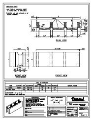
Figure 1.2 – Standard Wall Form Schematic ................................................................................................ 8<br />
Figure 1.3 – Standard Wall Form Schematic (SI) ......................................................................................... 9<br />
Figure 1.4 – Thermal Wall Form Schematic ............................................................................................... 10<br />
Figure 1.5 – Thermal Wall Form Schematic (SI)......................................................................................... 11<br />
Figure 2.1 – Typical Step Footing ............................................................................................................... 15<br />
Figure 2.2 – Typical Reinforcement Placement .......................................................................................... 20<br />
Figure 2.3 – Window Opening and Buck Detail .......................................................................................... 23<br />
Figure 2.4 – Window Buck at Jamb Detail 1 ............................................................................................... 24<br />
Figure 2.5 – Window Buck at Jamb Detail 2 ............................................................................................... 25<br />
Figure 2.6 – Window Buck Detail at <strong>Durisol</strong> Lintel ...................................................................................... 26<br />
Figure 2.7 – Window Buck Detail at Non-<strong>Durisol</strong> Lintel .............................................................................. 27<br />
Figure 2.8 – T-Wall Construction ................................................................................................................ 29<br />
Figure 2.9 – Non-90 o Corners ..................................................................................................................... 30<br />
Figure 2.10 – <strong>Durisol</strong> Wall Alignment Wedges .......................................................................................... 32<br />
Figure 2.11 – <strong>Durisol</strong> Wall Alignment / Bracing System ............................................................................ 33<br />
Figure 2.12 – Electrical Service Installation ............................................................................................... 35<br />
�<br />
ii
Technical Guide – Wall Form System<br />
TABLE OF CONTENTS<br />
Figure 4.1 – Masonry Veneer Detail 1 ....................................................................................................... 47<br />
Figure 4.2 – Masonry Veneer Detail 2 ....................................................................................................... 48<br />
Figure 4.3 – Masonry Veneer Detail 3 ....................................................................................................... 49<br />
Figure 4.4 – Strapping Attachment Plates ................................................................................................. 51<br />
Figure 4.5 – Siding Attachment Detail ....................................................................................................... 52<br />
LIST OF TABLES<br />
Table 1.1 – <strong>Building</strong> Material Off-Gas Test Results ...................................................................................... 3<br />
Table 1.2 – STC Rating of Typical <strong>Durisol</strong> Wall <strong>Systems</strong> ............................................................................. 3<br />
Table 1.3 – Thermal Bridging Effects of <strong>Durisol</strong> vs. Conventional Wall Construction .................................. 5<br />
Table 1.4 – Termite Resistance of <strong>Durisol</strong> .................................................................................................... 6<br />
Table 1.5 – Standard Wall Form Dimensions (Imperial) ............................................................................... 8<br />
Table 1.6 – Standard Wall Form Dimensions (SI) ........................................................................................ 9<br />
Table 1.7 – Thermal Wall Form Dimensions (Imperial) .............................................................................. 10<br />
Table 1.8 – Thermal Wall Form Dimensions (SI) ........................................................................................ 11<br />
Table 1.9 – Wall Form Types and Availability (Nominal Dimensions) ........................................................ 12<br />
Table 1.10 – Wall System Summary ........................................................................................................... 12<br />
Table 3.1 – Fastener Types and Pull-out Loads ......................................................................................... 40<br />
PHOTOGRAPHIC RECORDS<br />
Typical Projects ........................................................................................................................................... 56<br />
Construction Photographs ........................................................................................................................... 63<br />
�<br />
iii
Technical Guide – Wall Form System<br />
WARRANTY<br />
We warranty our products to be free of defects and manufactured to meet published physical properties<br />
when cured and tested according to ASTM, CSA and <strong>Durisol</strong> Standards.<br />
Under this warranty, <strong>Durisol</strong> will provide replacement product for any <strong>Durisol</strong> Wall Form proven to be<br />
defective when applied in accordance with written instructions and in applications recommended by<br />
<strong>Durisol</strong> for this product.<br />
All claims must be made within 1 (one) year of shipment. Absence of such claim in writing during this<br />
period will constitute a waiver of all claims with respect of such products.<br />
This warranty is in lieu of any and all other warranties expressed and implied.<br />
DISCLAIMER<br />
The recommendations, suggestions, statements and technical data in this technical guide are based on<br />
<strong>Durisol</strong>’s best knowledge. They are given for informational purposes only and are not to be<br />
construed as overriding any requirements of any applicable building code.<br />
<strong>Durisol</strong> <strong>Building</strong> <strong>Systems</strong> <strong>Inc</strong>. has no control over installation, workmanship, inspection, building<br />
conditions or applications. There is no responsibility, expressed or implied warranty, either as to<br />
merchantability or fitness for the particular purpose, made as to the performance or results of an<br />
installation using <strong>Durisol</strong> Wall Forms.<br />
Structures built with the <strong>Durisol</strong> Wall Forms should be designed and constructed in accordance with<br />
applicable building codes. <strong>Durisol</strong> material is not designed to carry any structural load other than<br />
temporary concrete pressures that occur during construction. The concrete core within the Wall<br />
Form is intended to be the primary load carrying material of the wall system. The design of the <strong>Durisol</strong><br />
wall system should be conducted and reviewed by an engineer.<br />
<strong>Durisol</strong> material is not designed to prevent the penetration of moisture through the wall system.<br />
The design of the <strong>Durisol</strong> wall system should be conducted and reviewed by a design professional to<br />
ensure there is a properly designed weather barrier with adequate flashing to prevent the penetration of<br />
moisture through the wall and into the interior.<br />
This document is not intended to override any applicable codes and practices that may be required in<br />
local jurisdictions. The user should refer to applicable building code requirements when exceeding the<br />
limitations of this document, when requirements conflict with the building code, or when an engineered<br />
design is specified. This specification is not intended to limit the appropriate use of concrete or<br />
construction not specifically prescribed. This document is also not intended to restrict the use of sound<br />
judgment or exact engineering analysis of specific applications that may result in designs with improved<br />
performance and economy.<br />
�<br />
iv
Overview – Wall Form System �<br />
1.0 <strong>SYSTEM</strong> OVERVIEW<br />
The <strong>Durisol</strong> Wall System is a proven method of constructing modular insulated concrete walls with over<br />
50 years of in-place experience. It is based on simple interlocking wall form units that are made from the<br />
unique <strong>Durisol</strong> material. <strong>Durisol</strong> is a proprietary material that is composed of only natural raw materials;<br />
specially graded wood chips (100% natural lumber) and Portland cement. We do not use polystyrene,<br />
foams, plastics or other potentially detrimental materials in the manufacture of our products.<br />
The wood chips are mineralized and bonded under pressure with Portland cement. The resulting<br />
lightweight, open-textured product is highly durable, practically incombustible and resistant to insects and<br />
rot.<br />
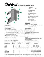
Figure 1.1 – Wall Form System Overview<br />
1.1 <strong>Durisol</strong> Wall Forms<br />
1.Optional Mortar Bed<br />
2.Levelling Shims<br />
3.Wall Reinforcing<br />
4.Lintel Reinforcing<br />
5.Lintel Form<br />
6.Square End Form<br />
7.Corner Form<br />
The Wall Form units are approximately 12” high and either 24” or 36” long. They are available in<br />
various widths. The units are dry-stacked and filled with concrete and reinforcing steel. This efficient<br />
method of concrete construction results in a wall that has built-in thermal, fire and acoustic protection.<br />
1
Overview – Wall Form System �<br />
The standard Non-thermal Wall Form unit has an insulation value of R8. Additional insulation inserts<br />
made from various materials may also be incorporated directly within the Wall Form at the time of<br />
manufacturing. Currently the most common type of insert is made from mineral fibre insulation, which<br />
can provide for insulation values that range from R14 to R28+, depending on the specific application.<br />
1.2 Applications<br />
<strong>Durisol</strong> Wall Forms have been used worldwide in every possible building application both above and<br />
below-grade. In our 50-year history of <strong>Durisol</strong> Wall Forms, wall systems have been constructed for<br />
use in the following:<br />
- Residential (Single and Multi-Unit)<br />
- Industrial<br />
- Agricultural<br />
- Commercial<br />
- Institutional<br />
- High Rise (Over 26 story buildings in-place)<br />
<strong>Durisol</strong> Wall Forms have been designed to accommodate all practical ranges of concrete thickness.<br />
The load carrying capacity of the wall system depends entirely upon the thickness of the concrete<br />
core and the steel reinforcing schedule.<br />
The 4-hour Fire Resistance Rating of the 8” Wall Form makes the <strong>Durisol</strong> wall system ideal for use as<br />
a party wall or common wall between residential units. The high Sound Transmission Class Rating<br />
(STC) of over 52 provides for quiet living in apartments or next to highways, railroad tracks, airports<br />
and other loud environments.<br />
1.3 Performance Advantages<br />
The <strong>Durisol</strong> Wall System has a unique combination of desirable properties. In-service advantages<br />
are outlined as follows:<br />
1.3.1 IMPACT RESISTANCE<br />
Standard stuccos applied directly to the <strong>Durisol</strong> material result in a finish that is less expensive<br />
and more impact resistant than conventional EIFS systems (polystyrene, lath and stucco).<br />
1.3.2 IMPROVED INDOOR AIR QUALITY<br />
The cement content of the <strong>Durisol</strong> material creates an above average pH environment at the wall<br />
surface, which inhibits the growth of fungi and viruses. The <strong>Durisol</strong> material is completely inert<br />
with no VOCs or off-gasing. Furthermore, the hygroscopic nature of the material moderates RH<br />
level. This regulation of water vapour keeps humidity low and further serves to repress any type<br />
2
Overview – Wall Form System �<br />
of fungal growth. The following table summarizes the levels of VOCs that are emitted by various<br />
construction materials:<br />
Table 1.1 – <strong>Building</strong> Material Off-Gas Test Results<br />
Material TVOCs<br />
( � g m �<br />
2 h<br />
)<br />
Water Extract<br />
Formaldehyde<br />
( � g g)<br />
Isocyanurate Foam < 1 < 2<br />
Glass Fiber Batt 3.6 200<br />
<strong>Durisol</strong> < 10 4<br />
Drywall 20 8<br />
Concrete Block 26 < 1<br />
Polystyrene 280 < 2<br />
Laminate / Particle Board 590 420<br />
1.3.3 SOUND PROTECTION<br />
Notes:<br />
1. Test conducted by Ortech as part of report submitted to Canada<br />
Mortgage and Housing Corp for Build Green Program (1995).<br />
<strong>Durisol</strong> wall systems provide considerable protection against unwanted noise. The sound<br />
absorptive properties of our material in combination with the mass of the wall system can provide<br />
an ideal combination of sound absorption and sound transmission properties. STC ratings for<br />
<strong>Durisol</strong> wall systems can range between 52 and 68, while the exposed surface of the <strong>Durisol</strong> Wall<br />
Form can provide Noise Reduction Coefficient (NRC) ratings as high as 1.0.<br />
Table 1.2 – STC Rating of Typical <strong>Durisol</strong> Wall <strong>Systems</strong><br />
Wall System STC Rating<br />
WF20 (8”) + plaster / EIFS 52<br />
WF20 (8”) + plaster/stucco 56<br />
WF25 (10”) + plaster/stucco 64<br />
WF30 (12”) + plaster/stucco 68<br />
Notes:<br />
2. Higher STC ratings are possible by altering wall configurations.<br />
3. Test Reports are available upon request.<br />
3
Overview – Wall Form System �<br />
1.3.4 THERMAL MASS EFFECT<br />
Materials like concrete, brick, and <strong>Durisol</strong> have a high heat capacity; that is, they can store a<br />
significant amount of heat energy. This benefit of thermal mass, as the ability to store heat is<br />
called, results in reduced heating costs as the energy/heat in the wall is transferred back into the<br />
cooler air. Similarly, when the surrounding air is warmer than the walls, heat will be transferred to<br />
the thermal mass and reduce cooling energy consumption. The benefits of thermal mass are<br />
increased through the use of <strong>Durisol</strong> Wall Forms since the majority of the insulation is located on<br />
the exterior face of the wall system. This is unlike foam concrete forms that have 50% of the<br />
insulation on the interior face and reduce the net benefit that is obtained through the effects of<br />
thermal mass.<br />
The true benefit that is realized from thermal mass effects depends on a number of site-specific<br />
parameters such as climatic conditions and building orientation. Simple blanket statements such<br />
as “R-40 when including thermal mass” are inaccurate and misleading. <strong>Durisol</strong> <strong>Building</strong> <strong>Systems</strong><br />
has a staff of engineers experienced in the field of <strong>Building</strong> Science who will provide customers<br />
with detailed evaluation of thermal mass effects upon request. Alternately, publications such as<br />
ASHRAE Fundamentals or ASHRAE Standard 90.1 will provide guidance to evaluation of<br />
different wall systems and corresponding dynamic effects.<br />
1.3.5 NEGLIGIBLE THERMAL BRIDGING<br />
<strong>Durisol</strong> and framed wall systems are not simple one-dimensional assemblies. Real buildings are<br />
three-dimensional, with corners, window openings, etc. However, most wall R-value calculation<br />
methods, and almost all marketing brochures, do not factor in the effects of framing at windows,<br />
doors, corners, etc. Thus they tend to over-estimate the true thermal performance.<br />
The construction details that increase heat flow through a framed wall system have little or no<br />
influence on the heat flow through the <strong>Durisol</strong> Insulated Wall Form System. <strong>Durisol</strong> Wall Forms<br />
are designed to ensure that the R-value through the core of the wall is almost the same as that<br />
through the web. This not only avoids thermal short-circuiting, it ensures uniform wall<br />
temperatures with no cold spots to encourage condensation, create discomfort, or cause dust<br />
marking.<br />
Recent studies by Oakridge National Labs, ASHRAE 90.1 committee and other independent<br />
research agencies have shown how these factors influence the overall performance of wall<br />
systems (see following table).<br />
4
Overview – Wall Form System �<br />
Table 1.3 – Thermal Bridging Effects of <strong>Durisol</strong> vs. Conventional Wall Construction<br />
Wall Type Nominal R-value Whole Wall R-value<br />
2x6 (24” o/c) wood stud with<br />
R-19 batt insulation<br />
2x4 (24” o/c) metal studs with<br />
R-11 batt insulation + 1”<br />
continuous EPS on exterior<br />
R-20 R-13.7<br />
R-17 R-10.2<br />
<strong>Durisol</strong> WF30 T3 (12” R-20) R-20 R-19.8<br />
Notes:<br />
1. The above Whole Wall insulation value considers thermal bridging effects only.<br />
2. Mass effects will further increase the relative performance of <strong>Durisol</strong> and other mass wall systems.<br />
3. Contact <strong>Durisol</strong> for detailed evaluation of dynamic thermal performance.<br />
1.3.6 FIRE RESISTANCE<br />
The fire resistant properties of <strong>Durisol</strong> itself and the <strong>Durisol</strong> wall system as a whole provide<br />
considerable protection from fires. Tests in Canada have been conducted for two and four-hour<br />
fire ratings while in Austria, six-hour fire ratings have been obtained.<br />
The surface burning characteristics of <strong>Durisol</strong> far surpass all other types of stay-in-place<br />
formwork. <strong>Durisol</strong> has a flame spread and smoke spread rating of zero. Unlike foam, <strong>Durisol</strong> will<br />
not ignite, melt, sustain fire or release toxic fumes in the event of a fire.<br />
- Over 4 hour Fire Resistance Rating<br />
- Zero Flame Spread<br />
- Zero Smoke Developed<br />
- Zero Fuel Contributed<br />
1.3.7 MOISTURE PROTECTION<br />
Since no exterior finish will act as a perfect rain barrier, it is good practice to have a wall system<br />
that is capable of compensating for imperfections in the veneer. In the event that moisture does<br />
become temporarily trapped within the wall, the <strong>Durisol</strong> is capable of accommodating this<br />
moisture without any damage to itself. Damage to other wall components is of course a<br />
possibility. Although the <strong>Durisol</strong> material will not prevent moisture damage, it will mitigate the<br />
effects of moisture penetration through the exterior weather barrier. The behavior of <strong>Durisol</strong> in<br />
this regard is similar to any other type of cement based product with moisture storage capability -<br />
such as concrete masonry. The permeable nature of the <strong>Durisol</strong> serves to regulate the water<br />
vapour in the air and provides a smoothing effect to rapid swings in relative humidity.<br />
5
Overview – Wall Form System �<br />
1.3.8 TERMITE RESISTANCE<br />
Unlike foam insulation, <strong>Durisol</strong> provides effective resistance to termite attack. A number of<br />
testing programs have been conducted where <strong>Durisol</strong> samples were placed in termite infested<br />
areas for as long as six years without any destruction of <strong>Durisol</strong> material occurring.<br />
Test Sample<br />
<strong>Durisol</strong> placed on surface at<br />
termite test site<br />
<strong>Durisol</strong> placed 2” below-grade<br />
at termite test site<br />
<strong>Durisol</strong> set on wood base<br />
placed on surface of test site<br />
<strong>Durisol</strong> placed 2” below-grade<br />
on wood base at test site<br />
<strong>Durisol</strong> set 3” above grade on<br />
masonry base at test site<br />
<strong>Durisol</strong> stored inside (no<br />
exposure to termites)<br />
Table 1.4 – Termite Resistance of <strong>Durisol</strong><br />
Panel Damage Index (PDI)<br />
3 years 4 years 5 years 6 years<br />
0.4 0.8 1.0 1.0<br />
0.4 0.6 1.0 1.0<br />
0.6 0.6 1.0 1.0<br />
0.8 0.6 1.0 1.0<br />
0.2 0.6 0.6 1.0<br />
0 0 0 0<br />
Control wood samples 5 4 4.5 5<br />
* Summary of test report FS-SRS-4502-4.204 conducted by US Forest Service at termite<br />
facilities in Mississippi and Arizona. Contact <strong>Durisol</strong> for detailed test information.<br />
PDI: 0.0 - Sound; no feeding or surface investigation<br />
1.0 - Surface investigation only<br />
2.0 - Light Damage; penetration into panel<br />
3.0 - Moderate Damage; penetration into panel<br />
4.0 - Heavy Damage; extensive penetration and damage to panel<br />
5.0 - Failure; complete or near complete destruction of panel<br />
1.4 Construction Advantages<br />
<strong>Durisol</strong> Wall Forms are lightweight and straightforward to use. With each Wall Form unit covering<br />
approximately 3 ft 2 (0.028m 2 ) of wall area, construction is fast and efficient. This results in lower<br />
labour costs and shorter construction time.<br />
The <strong>Durisol</strong> material can be easily cut, nailed and screwed with simple carpenter tools. This provides<br />
the builder with the flexibility to cut and fit shapes to suit site-specific situations. Wood bucks and<br />
bracing can be directly attached to the <strong>Durisol</strong> Wall Forms using nails and screws.<br />
6
Overview – Wall Form System �<br />
The insulating properties of <strong>Durisol</strong> Wall Forms allow winter construction without additional heating or<br />
insulation sources being required. <strong>Durisol</strong> wall systems have been constructed in temperatures as<br />
low as 22 �F (- 6�C) without any complication.<br />
The unique free-draining <strong>Durisol</strong> material allows the use of high-slump concrete in the field that<br />
makes for easier and faster concrete pouring that ensures a solid wall without any compromise in<br />
strength. Ideally, concrete with a slump between 7” and 9” is recommended for use in conjunction<br />
with <strong>Durisol</strong>.<br />
Interior and exterior finishes are applied directly to the <strong>Durisol</strong> material, eliminating subsequent steps<br />
in the construction process. Drywall can be attached anywhere on the Wall form surface, while the<br />
open-textured nature of hardened <strong>Durisol</strong> makes it an ideal substrate for plasters and stucco.<br />
1.5 Design Flexibility<br />
<strong>Durisol</strong> Wall Forms can be ordered with R-values ranging from R-8 to R-28+. This allows for optimal<br />
wall design catered to the specific applications (i.e. above-grade, below-grade, residential,<br />
commercial, etc). Designs can be customized to suit the needs of the project and provide the most<br />
cost-effective solution without compromising performance of the building envelope.<br />
1.6 Research and Testing<br />
<strong>Durisol</strong> is committed to research and development, with over 50 years of independent research, inhouse<br />
testing and continuous improvement. Specific test reports on topics such as thermal<br />
resistance, fire performance, termite resistance, etc., may be available upon request.<br />
7
Overview – Wall Form System �<br />
1.7 Standard Wall Forms (Imperial)<br />
* Configuration of horizontal interlock varies among<br />
Wall Form types<br />
Figure 1.2 - Standard Wall Form Schematic<br />
Wall<br />
Form<br />
Type<br />
6” WF<br />
8” WF<br />
10” WF<br />
12” WF<br />
14” WF<br />
Plan View<br />
Wall<br />
Form<br />
Weight<br />
(lbs)<br />
16<br />
33<br />
40<br />
31<br />
38<br />
T<br />
(in)<br />
5 7/8<br />
7 7/8<br />
10<br />
12<br />
14<br />
Table 1.5 - Standard Wall Form Dimensions (Imperial)<br />
t<br />
(in)<br />
1 3/8<br />
1 5/8<br />
1 3/4<br />
1 3/4<br />
1 3/4<br />
2”<br />
2”<br />
<strong>FORM</strong> DIMENSIONS<br />
a<br />
(in)<br />
1 7/8<br />
1 3/4<br />
1 3/4<br />
1 3/4<br />
2<br />
Section<br />
c<br />
(in)<br />
1 3/4<br />
1 1/2<br />
1 3/4<br />
1 3/4<br />
1 3/4<br />
12”<br />
w<br />
(in)<br />
3 1/4<br />
4 3/8<br />
6 3/4<br />
8 1/2<br />
10 3/8<br />
Standard - 3 Core<br />
(8” & 10” WF only)<br />
L - Corner<br />
(8” & 10” WF only)<br />
End<br />
(14” WF only)<br />
split/End = 2 Half Form<br />
(8”, 10”, 12” WF only)<br />
Standard - 2 Core<br />
(6”, 12”, 14” WF only)<br />
b<br />
(in)<br />
9 1/8<br />
9 1/2<br />
9 1/2<br />
9 3/8<br />
9 1/8<br />
h<br />
(in)<br />
3 1/8<br />
4 3/4<br />
6 3/4<br />
8 1/2<br />
10 3/8<br />
CONCRETE CORE<br />
DATA<br />
X-Sect<br />
Area<br />
(in 2 )<br />
28.5<br />
44.3<br />
64.1<br />
79.7<br />
94.5<br />
Fill<br />
Volume<br />
(yd 3 / ft 2 )<br />
0.0088<br />
0.0132<br />
0.0173<br />
0.0221<br />
0.0273<br />
8
Overview – Wall Form System �<br />
1.8 Standard Wall Forms (SI)<br />
* Configuration of horizontal interlock varies among<br />
Wall Form types<br />
Figure 1.3 - Standard Wall Form Schematic (SI)<br />
Wall<br />
Form<br />
Type<br />
6” WF<br />
8” WF<br />
10” WF<br />
12” WF<br />
14” WF<br />
Plan View<br />
Wall<br />
Form<br />
Weight<br />
(kg)<br />
8<br />
15<br />
18<br />
14<br />
17<br />
T<br />
(mm)<br />
150<br />
200<br />
255<br />
305<br />
360<br />
Table 1.6 - Standard Wall Form Dimensions (SI)<br />
t<br />
(mm)<br />
35<br />
40<br />
42<br />
45<br />
45<br />
50<br />
50<br />
<strong>FORM</strong> DIMENSIONS<br />
a<br />
(mm)<br />
46<br />
43<br />
45<br />
45<br />
51<br />
Section<br />
c<br />
(mm)<br />
46<br />
38<br />
45<br />
45<br />
48<br />
305<br />
w<br />
(mm)<br />
80<br />
120<br />
172<br />
216<br />
265<br />
Standard - 3 Core<br />
(8” & 10” WF only)<br />
L - Corner<br />
(8” & 10” WF only)<br />
b<br />
(mm)<br />
233<br />
238<br />
242<br />
238<br />
232<br />
End<br />
(14” WF only)<br />
split/End = 2 Half Form<br />
(8”, 10”, 12” WF only)<br />
Standard - 2 Core<br />
(6”, 12”, 14” WF only)<br />
h<br />
(mm)<br />
80<br />
120<br />
172<br />
216<br />
265<br />
CONCRETE CORE<br />
DATA<br />
X-Sect<br />
Area<br />
(mm 2 )<br />
18650<br />
28000<br />
41500<br />
51400<br />
61500<br />
Fill<br />
Volume<br />
(m 3 / m 2 )<br />
0.073<br />
0.109<br />
0.142<br />
0.182<br />
0.225<br />
9
Overview – Wall Form System �<br />
1.9 Thermal Wall Forms (Imperial)<br />
12” 12” 12”<br />
Plan View<br />
* Configuration of horizontal interlock varies among<br />
Wall Form types<br />
Figure 1.4 - Thermal Wall Form Schematic<br />
Wall<br />
Form<br />
Type<br />
10” WF (R-14)<br />
12” WF (R-14)<br />
12” WF (R-21)<br />
14” WF (R-14)<br />
14” WF (R-21)<br />
14” WF (R-28)<br />
Wall<br />
Form<br />
Weight<br />
(lbs)<br />
43<br />
35<br />
39<br />
39<br />
41<br />
44<br />
Table 1.7 - Thermal Wall Form Dimensions (Imperial)<br />
T<br />
(in)<br />
10<br />
12<br />
12<br />
14<br />
14<br />
14<br />
t<br />
(in)<br />
1 3/4<br />
1 3/4<br />
1 3/4<br />
1 3/4<br />
1 3/4<br />
1 3/4<br />
Section<br />
<strong>FORM</strong> DIMENSIONS<br />
a<br />
(in)<br />
1 3/4<br />
1 3/4<br />
1 3/4<br />
2<br />
2<br />
2<br />
2”<br />
2”<br />
c<br />
(in)<br />
1 3/4<br />
1 3/4<br />
1 3/4<br />
1 3/4<br />
1 3/4<br />
1 3/4<br />
12”<br />
Standard - 3 Core<br />
(8” & 10” WF only)<br />
L - Corner<br />
(8” & 10” WF only)<br />
w<br />
(in)<br />
5 1/4<br />
7<br />
5 1/2<br />
9<br />
7 1/2<br />
5 1/2<br />
End<br />
(14” WF only)<br />
split/End = 2 Half Form<br />
(8”, 10”, 12” WF only)<br />
Standard - 2 Core<br />
(6”, 12”, 14” WF only)<br />
i<br />
(in)<br />
1 1/2<br />
1 1/2<br />
3<br />
1 1/2<br />
3<br />
5<br />
b<br />
(in)<br />
9 1/2<br />
9 3/8<br />
9 3/8<br />
9 1/8<br />
9 1/8<br />
9 1/8<br />
h<br />
(in)<br />
5 1/4<br />
7<br />
5 1/2<br />
9<br />
7 1/2<br />
5 1/2<br />
CONCRETE CORE<br />
DATA<br />
X-Sect<br />
Area<br />
(in 2 )<br />
49.9<br />
65.6<br />
52.3<br />
82.1<br />
68.4<br />
50.2<br />
Fill<br />
Volume<br />
(yd 3 / ft 2 )<br />
0.0130<br />
0.0180<br />
0.0130<br />
0.0230<br />
0.0180<br />
0.0120<br />
10
Overview – Wall Form System �<br />
1.10 Thermal Wall Forms (SI)<br />
* Configuration of horizontal interlock varies among<br />
Wall Form types<br />
Figure 1.5 - Thermal Wall Form Schematic (SI)<br />
Wall<br />
Form<br />
Type<br />
10” WF (R-14)<br />
12” WF (R-14)<br />
12” WF (R-21)<br />
14” WF (R-14)<br />
14” WF (R-21)<br />
14” WF (R-28)<br />
305 305 305<br />
Plan View<br />
Wall<br />
Form<br />
Weight<br />
(kg)<br />
20<br />
18<br />
19<br />
19<br />
20<br />
21<br />
Table 1.8 - Thermal Wall Form Dimensions (SI)<br />
T<br />
254<br />
305<br />
305<br />
360<br />
360<br />
360<br />
t<br />
45<br />
45<br />
45<br />
45<br />
45<br />
45<br />
Section<br />
<strong>FORM</strong> DIMENSIONS (mm)<br />
a<br />
45<br />
45<br />
45<br />
51<br />
51<br />
51<br />
c<br />
45<br />
45<br />
45<br />
48<br />
48<br />
48<br />
50<br />
50<br />
305<br />
w<br />
133<br />
178<br />
140<br />
227<br />
190<br />
138<br />
Standard - 3 Core<br />
(8” & 10” WF only)<br />
L - Corner<br />
(8” & 10” WF only)<br />
End<br />
(14” WF only)<br />
split/End = 2 Half Form<br />
(8”, 10”, 12” WF only)<br />
Standard - 2 Core<br />
(6”, 12”, 14” WF only)<br />
i<br />
38<br />
38<br />
76<br />
38<br />
76<br />
127<br />
b<br />
241<br />
238<br />
238<br />
232<br />
232<br />
232<br />
h<br />
133<br />
178<br />
140<br />
227<br />
190<br />
138<br />
CONCRETE CORE<br />
DATA<br />
X-Sect<br />
Area<br />
(mm 2 )<br />
32100<br />
42300<br />
33700<br />
52650<br />
44100<br />
32100<br />
Fill<br />
Volume<br />
(m 3 / m 2 )<br />
0.109<br />
0.143<br />
0.105<br />
0.186<br />
0.148<br />
0.098<br />
11
Overview – Wall Form System �<br />
1.11 Wall System Summary<br />
The following Tables summarize the Wall Forms and overall wall systems that are possible using the<br />
standard <strong>Durisol</strong> Wall Forms.<br />
Wall Form Shape<br />
Standard 3 Core<br />
L - Corner (2 Core) 1<br />
Corner (Modified End)<br />
End (2 Core)<br />
Split/End (2 Core)<br />
Standard 2 Core<br />
Table 1.9 – Wall Form Types and Availability (Nominal Dimensions)<br />
Size<br />
(height x<br />
length)<br />
(12” x 36”)<br />
(12” x 24”)<br />
(12” x 24”)<br />
(12” x 24”)<br />
(12” x 24”)<br />
(12” x 24”)<br />
6” WF<br />
�<br />
�<br />
�<br />
�<br />
�<br />
�<br />
8” WF<br />
�<br />
�<br />
�<br />
�<br />
�<br />
�<br />
AVAILABILITY<br />
10” WF<br />
�<br />
�<br />
�<br />
�<br />
�<br />
�<br />
12” WF<br />
�<br />
�<br />
�<br />
�<br />
�<br />
�<br />
14” WF<br />
1<br />
All Corner Wall Forms are L-shaped with 12” return. Since the WF30 system has a thickness of 12” ,<br />
the corner unit is a modified End Unit.<br />
Table 1.10 - Wall System Summary<br />
Concrete Weight<br />
Wall Thickness Fill Vol. of Wall<br />
Thickness R‐Value (in) (yd 3 / ft 2 ) (LB / ft 2 ) Application<br />
6"* 8 3 1/8 0.0089 50 ABOVE GRADE<br />
8" 8 4 3/4 0.0132 69 ABOVE GRADE<br />
10" 8 6 3/4 0.0173 87 ABOVE & BELOW GRADE<br />
10" 14 5 1/4 0.0132 82 ABOVE GRADE<br />
12" 8 8 1/2 0.0222 112 ABOVE & BELOW GRADE<br />
12" 14 7 0.0174 94 ABOVE & BELOW GRADE<br />
12" 21 5 1/2 0.0127 76 ABOVE GRADE<br />
14" 8 10 3/8 0.0273 137 ABOVE & BELOW GRADE<br />
14" 14 9 0.0227 118 ABOVE & BELOW GRADE<br />
14" 21 7 1/2 0.018 100 ABOVE & BELOW GRADE<br />
14" 28 5 1/2 0.0118 76 ABOVE GRADE<br />
* 6” WF is not typically intended for use as a load-bearing wall.<br />
�<br />
�<br />
�<br />
�<br />
�<br />
�<br />
12
Installation – Wall Form System �<br />
2.0 INSTALLATION<br />
2.1 General<br />
<strong>Durisol</strong> insulating concrete forms are modular building blocks with the versatility to be designed to suit<br />
any wall dimension and any wall height. The blocks can be cut easily, providing the length and height<br />
of wall dimensions required<br />
<strong>Durisol</strong> ICFs can be used for any building project application, including above and below grade walls,<br />
both interior and exterior walls, and multi-story or tall wall applications. Since 1953, <strong>Durisol</strong> has been<br />
used for all building types, including residential, institutional, commercial, industrial, or agricultural<br />
applications.<br />
Throughout this section, you will see various symbols for bullet points. They have the following<br />
specific definitions:<br />
INSTALLATION GUIDE ICONS<br />
This icon refers to items that provide additional information and things to be considered.<br />
This icon refers to items that are recommended to be followed to ensure a successful<br />
<strong>Durisol</strong> installation.<br />
This Installation Guide has been prepared with the assumption that the reader has a basic knowledge<br />
of conventional construction methods and terminology. It is strongly recommended that anyone<br />
building with <strong>Durisol</strong> ICF successfully complete an <strong>Durisol</strong> training course to become a trained<br />
installer of ICFs. This training course is offered frequently and will provide knowledge and tips to<br />
ensure a successful and efficient build with <strong>Durisol</strong> ICFs. Although insulating concrete forms are<br />
relatively easy to install, the installation of reinforcing steel, placement of concrete and working from a<br />
scaffold may be new to some builders. The <strong>Durisol</strong> technical support team is available to answer<br />
questions.<br />
2.1 Modular Planning and Design<br />
In designing with <strong>Durisol</strong> ICFs, it is recommended that the overall design approach integrate the<br />
natural coursing of the blocks, which is on a 12” increment both horizontally and vertically. The<br />
<strong>Durisol</strong> Wall Form units are nominally 12” high x 36” long and come in various widths. Although it is<br />
not a requirement, planning the building layout on a 12” (305mm) horizontal module and 12” (305mm)<br />
vertical module will increase speed of construction. Also, having openings that are sized and placed<br />
on this 12” module will further increase the productivity of construction. Depending on how tightly the<br />
Wall Forms are stacked next to each other, a wall length can increase by as much as 1.5% during<br />
13
Installation – Wall Form System �<br />
construction. For example 10 Wall Forms laid side by side can measure as much as 365” if not tightly<br />
placed next to each other. If the Wall Forms do require cutting, it is easily accomplished with a hand,<br />
circular, reciprocating saw or even chainsaw. Where cutting has destroyed the inherent stability of a<br />
Wall Form, pieces can be screwed together temporarily using ordinary wood screws.<br />
HORIZONTAL <strong>WALL</strong> DIMENSIONS SHOULD BE 12” INCREMENTS X 1.015 TO FIT “AS<br />
INSTALLED” BLOCK DIMENSIONS.<br />
OVERALL VERTICAL <strong>WALL</strong> HEIGHTS SHOULD BE 12” INCREMENTS<br />
HORIZONTAL SPACING BETWEEN OPENINGS SHOULD BE ON 12” INCREMENTS X<br />
1.015. ROUGH OPENING WIDTHS CAN BE ANY SIZE<br />
ROUGH OPENING HEIGHTS SHOULD ALIGN WITH GENERAL COURSING (12”<br />
INCREMENTS)<br />
<strong>DURISOL</strong> CAN PROVIDE CUSTOM HEIGHT UNITS FOR ANY PROJECT. SIMPLY<br />
INCLUDE THE TYPE OF UNIT, HEIGHT OF UNIT REQUIRED AND QUANTITY AT THE<br />
TIME OF ORDER.<br />
2.2 Footings and Slabs-on-Grade<br />
When considering the footings of a building, there is no differentiation between <strong>Durisol</strong> walls and<br />
concrete walls that are constructed using conventional forming techniques. The <strong>Durisol</strong> Wall Form<br />
system results in reinforced concrete walls that are range in thickness from 5.25” to 10.4”. Footings<br />
should be designed and constructed as following normal good practice, and in strict compliance with<br />
local building codes and regulations.<br />
As with any type of construction, it is good practice to ensure that all footings are level. In the event<br />
that site conditions require step footings, it is recommended that vertical steps of 12” be used to<br />
correspond with the height of the <strong>Durisol</strong> Wall Form units. This will eliminate unnecessary on-site<br />
cutting of Wall Forms as courses can simply carry on past the footing over the course below.<br />
It is recommended that a key-way in the top of the footings be provided as well as steel reinforcing<br />
dowels that protrude from the top of the footing into the foundation wall. Although this is not required<br />
by most building codes, it is considered good building practice.<br />
14
Installation – Wall Form System �<br />
Figure 2.1 – Typical Step Footing<br />
117/8”<br />
Mortar Bed<br />
DUE TO THE WIDE VARIETY OF BUILDING CONDITIONS, IT IS RECOMMENDED THAT<br />
A LOCAL DESIGN PROFESSIONAL BE CONSULTED TO DETERMINE ALL RELEVANT<br />
FACTORS TO BE CONSIDERED WHEN DETERMINING DESIGN AND<br />
REINFORCEMENT FOR FOOTINGS AND SLABS ON GRADE.<br />
THE FOOTINGS OR SLAB ON GRADE TO SUPPORT A <strong>DURISOL</strong> <strong>WALL</strong> SHOULD BE<br />
DESIGNED AND CONSTRUCTED AS THEY WOULD BE FOR CONVENTIONAL<br />
CONCRETE <strong>WALL</strong> CONSTRUCTION, WITH STRICT COMPLIANCE TO APPLICABLE<br />
BUILDING CODES AND REGULATIONS. FOOTINGS OR SOG SHOULD ALWAYS BE<br />
CONSTRUCTED IN ACCORDANCE WITH THE CONSTRUCTION DRAWINGS.<br />
FOOTING STEP HEIGHTS SHOULD BE 12” INCREMENTS. LENGTH OF STEPS<br />
SHOULD BE 12’ INCREMENTS X 1.015.<br />
DOWELS FROM FOOTING SHOULD BE SPACED EITHER 24” OR 36” AND ALIGN WITH<br />
THE CORES OF THE <strong>DURISOL</strong> BLOCKS.<br />
DOWELS SHOULD PROJECT INTO THE <strong>DURISOL</strong> <strong>WALL</strong> MINIMUM 12” – 18”.<br />
12”<br />
12”<br />
15
Installation – Wall Form System �<br />
2.3 Wall Layout<br />
Once the footings are in place, it is necessary to check the exact building dimensions (if not<br />
surveyed) and ensure that all corners are square. Once the corners have been pinned according to<br />
the specified building measurements, the footing should be marked with a chalk line to represent the<br />
inside and outside edges of the Wall Form. It is good practice to fasten guide boards to the footing<br />
along marked chalk lines. This will prevent complications from inadvertent removal of the chalk line or<br />
wall movement. When laying out chalk lines on the inside face of a wall, it is suggested that lines be<br />
marked approximately ½” (12mm) off the actual layout. This offset will allow lines to remain visible if<br />
subsequent adjustment is required during the first course placement.<br />
Once the building is accurately laid out on the footing, mark locations of door and window openings<br />
for future reference.<br />
SET VERTICAL POSTS (2x4) PLUMB AND BRACED TO THE FOOTING THAT ALIGN<br />
WITH THE INTERIOR CORNERS OF THE STRUCTURE. THESE VERTICAL POSTS CAN<br />
THEN BE USED AS A GUIDE TO ENSURE THAT THE INTERIOR SURFACE OF THE<br />
<strong>WALL</strong> IS KEPT FLUSH AND IN LINE WITH THE INTENDED <strong>WALL</strong> LAYOUT<br />
2.4 Material Unloading and Placement<br />
The Wall Forms are shipped on either conventional 48” x 48” pallets, stacked 7 courses (7 ft) high or<br />
36” x 72” pallets stacked 6 high. Typically, the <strong>Durisol</strong> Wall Forms are shipped within a standard vanstyle<br />
trailer. Each pallet will weigh between 1400 and 2700 lbs (depending on Wall Form type), and a<br />
forklift will be required onsite for unloading of material. Forklifts are readily available at local<br />
construction equipment rental outlets at nominal cost.<br />
Stacking the Wall Forms is easier from the inside of the structure. For this reason, all material should<br />
be placed inside the perimeter of the wall. Ideally, Wall Form pallets should be placed at a 10-foot<br />
spacing along the length of the walls with approximately 7 feet of space between the pallet and<br />
footing. This will eliminate unnecessary movement of Wall Form units around the job site. When<br />
moving Wall Forms, use caution and avoid reckless handling. The rough texture of the <strong>Durisol</strong><br />
material makes it difficult to notice a damaged wall form.<br />
SET PALLETS ON THE INTERIOR OF THE STRUCTURE WHENEVER POSSIBLE.<br />
SPACE PALLETS EVERY 6FT AROUND PERIMETER<br />
16
Installation – Wall Form System �<br />
2.5 Placement of First Course<br />
Prior to placing the first course of <strong>Durisol</strong> Wall Forms, one should have the necessary material on<br />
hand for framing the rough window and door openings; using 2x8, 2x10 or 2x12 lumber, depending<br />
on the Wall Form thickness.<br />
Because footings and slabs are never 100% level, the first course should be set in a 1/2” to 1”<br />
leveling bed that will allow for accurate leveling of the first course. Accuracy at this stage assures<br />
that all subsequent courses are parallel, level and trouble free. Other materials such as construction<br />
adhesive may be used in lieu of conventional mortar. Adjusting the embedment of the Wall Forms in<br />
the mortar bed will compensate for most uneven footings. Another method for correcting uneven<br />
footings is to use shims to level successive courses. Finally, if the footing is drastically uneven, the<br />
bottom of the Wall Forms can be cut to fit the contour of the footing.<br />
Beginning at the corners, place a corner Wall Form so that it lines up with the building lines<br />
established earlier. The use of vertical guide boards at the corners can help in positioning the first<br />
and subsequent courses so that they do not move.<br />
When using Wall Forms with insulation inserts, ensure that the insulation is placed on the outside<br />
face of the wall (typical for temperate climates). By first placing the corner forms and stringing a<br />
plumb line between them, stacking the remaining forms is made easy and accurate.<br />
YOU CAN USE MORTAR, ADHESIVE OR SHIMS TO GET THE FIRST COURSE LEVEL.<br />
USE THE CORNER POSTS AS GUIDES FOR A STRINGLINE TO KEEP THE <strong>WALL</strong><br />
STRAIGHT<br />
17
Installation – Wall Form System �<br />
2.6 Placement of Subsequent Courses<br />
The second course can be stacked immediately after placement of the first course and horizontal<br />
reinforcement. Beginning with the corner, stagger the corner block so that the “running bond” pattern<br />
is created in the wall. The running bond pattern is not essential to the integrity of the wall system and<br />
is primarily employed to increase wall stability during construction. While creating the running bond<br />
pattern, it is essential to ensure that the vertical cores of the wall forms are aligned from one course<br />
to the next.<br />
Proceeding around the wall in the same direction as in the first course, a cutting pattern will be<br />
established that may be followed throughout the entire wall construction process. Following this<br />
method will group all cut forms in the same general location, thus ensuring easier installation of Wall<br />
Forms. Also, since all cut forms should be braced separately, grouping cut forms will minimize the<br />
extent of additional wall bracing required.<br />
Check to ensure the wall is level when the first two courses of forms have been placed. Courses<br />
above the first and second can be placed by following the pattern established in the first two courses.<br />
As stacking progresses, it will be necessary to accommodate the variances among Wall Form units<br />
by using shims, screws or other methods of adjustment (mortar, adhesive, etc.) to create a level and<br />
plumb wall prior to pouring.<br />
18
Installation – Wall Form System �<br />
AFTER THE FIRST COURSE, USE THE STRINGLINE TO KEEP THE <strong>WALL</strong> LEVEL<br />
EVERY 2 ND OR 3 RD COURSE.<br />
USE CARBIDE TIP BLADES, RECIPROCAL SAWS OR HAND SAWS TO CUT THE<br />
<strong>DURISOL</strong> <strong>FORM</strong>S WHEN REQUIRED.<br />
ALWAYS MARK THE LOCATION ON THE <strong>WALL</strong> WHERE <strong>DURISOL</strong> BLOCKS ARE CUT.<br />
ADDITIONAL BRACING FOR THE <strong>WALL</strong> BE REQUIRED HERE TO PREVENT<br />
BLOWOUTS.<br />
GROUP ALL THE CUT BLOCKS AT ONE LOCATION IN THE <strong>WALL</strong> WHEREVER<br />
POSSIBLE.<br />
YOU CAN STACK BOND BLOCKS WHERE REQUIRED INSTEAD OF THE NORMAL<br />
“RUNNING BOND” PATTERN.<br />
ALWAYS TRY TO ALIGN VERTICAL CORES<br />
2.7 Reinforcement<br />
The requirements for using reinforcing steel in <strong>Durisol</strong> walls are as per conventional reinforced<br />
concrete construction. The engineer’s structural drawings will provide the relevant information<br />
regarding bar size and spacing, splice lengths, clear cover from edge of poured concrete, etc.<br />
2.7.1 HORIZONTAL REINFORCING<br />
The engineering requirements will determine the size and position of the horizontal reinforcing.<br />
These requirements should be noted on the building drawings or engineers shop drawings.<br />
Horizontal reinforcing should be installed prior to the placement of the next course.<br />
19
Installation – Wall Form System �<br />
In below grade construction, the horizontal rebar can ensure the positioning of the vertical steel<br />
towards the inside face of the Wall Form while still maintaining the minimum required clear cover.<br />
In the case of above grade construction, the builder should stagger the horizontal rebar between<br />
the inside and outside groove. This allows the builder to easily slide the vertical reinforcing down<br />
from the top of the wall, so that the steel fits between the horizontal reinforcing (i.e. in the center<br />
of the wall).<br />
It is recommended to secure the horizontal rebar into position with a nail or clip every 6 feet. All<br />
reinforcing steel should be continuous, that is, lapped in accordance with applicable codes<br />
(typical minimum lap length is 40 x bar diameter) and bent around corners.<br />
PLACE HORIZONTAL REBAR AS YOU STACK THE BLOCKS. USE A SMALL<br />
FINISHING NAIL NEXT TO THE REBAR AND INTO THE WEB OF THE <strong>DURISOL</strong><br />
BLOCK TO KEEP THE HORIZONTAL REBAR FROM MOVING.<br />
2.7.2 VERTICAL REINFORCING<br />
Placing the vertical reinforcement so that it is positioned between the staggered horizontal rebar<br />
will ensure that the vertical reinforcing is held away from the face of the form, and guarantees that<br />
the required concrete cover will be maintained.<br />
Vertical reinforcement is inserted prior to, or immediately after the concrete has been placed. It<br />
should be continuous or lapped where required. Lapping of rebar should be avoided at the midheight<br />
of the wall and should be accommodated elsewhere along the height. Typically, the rebar<br />
will extend past the top of the pour sequence to accommodate the required lap lengths. All<br />
reinforcement requirements including minimum lap length should be based on the applicable<br />
concrete standards and building codes. The contractor should use a pouring sequence that<br />
ensures all bars meet the required minimum lap distances.<br />
Because of the relatively secured positioning of the reinforcement, tied reinforcement is not<br />
typically required.<br />
PLACE VERTICAL REBAR AFTER THE <strong>WALL</strong> IS STACKED, PRIOR TO POURING<br />
CONCRETE.<br />
<strong>DURISOL</strong> CAN PROVIDE BOTH STEEL AND GFRP REBAR WITH YOUR ORDER<br />
21
Installation – Wall Form System �<br />
2.8 Door and Window Openings<br />
Doors and window frames, whether wrap around or butt-type are easily installed while stacking Wall<br />
Forms. Openings in the <strong>Durisol</strong> wall system should be sized to accommodate the rough stud opening<br />
(RSO or RO) plus the thickness of the window buck. Also include any allowances necessary for<br />
exterior finishes. If <strong>Durisol</strong> End units are employed instead of wood bucks on the vertical sides of the<br />
opening, the horizontal opening length is not increased beyond the size of the RSO. Frames should<br />
have the same dimensions as the RSO dimensions supplied by the window or door manufacturer.<br />
Installing the frames during construction of the walls avoids the necessity for temporary opening<br />
bucks or <strong>Durisol</strong> End Units along the vertical sides and under the lintel. It also allows the fill concrete<br />
to flow directly against the frames to allow proper seal between the frames and the wall.<br />
It is the designer’s responsibility to ensure that all flashing and moisture protection around<br />
openings are adequately detailed to prevent moisture penetration.<br />
MAKE SURE THAT IF YOU ARE USING BUCKS FOR OPENINGS, THEY ARE<br />
ACCOUNTED FOR IN THE ROUGH OPENING DIMENSIONS AND THE WINDOW SIZE<br />
REQUIREMENTS.<br />
INSTALL WINDOW FLASHING, SILL BLOCKS AND ANY OTHER MOISTURE<br />
PROTECTION PRIOR TO INSTALLING WINDOWS.<br />
KEEP THE BOTTOMS (SILL) OF WINDOWS OPEN SO THAT THE CONCRETE CAN BE<br />
POURED AT THESE LOCATIONS. HAVE A WOOD BUCK ON HAND SO THAT WHEN<br />
THIS LEVEL IS REACHED IN THE POUR, THE SILLS CAN BE COVERED AND THE<br />
CONCRETE CAN BE CONTINUED TO BE POURED<br />
IF NOT USING BUCKS, METAL STRIPS WILL BE REQUIRED TO ENSURE THAT<br />
WINDOWS ARE FASTENED BACK TO CONCRETE CORE AND NOT JUST THE<br />
<strong>DURISOL</strong> MATERIAL.<br />
<strong>DURISOL</strong> CAN PROVIDE <strong>DURISOL</strong> AND INSULATION SEPARATELY IN SHEETS (24” X<br />
48” X 2” THICK). THIS WILL ALLOW THE INSTALLER TO MAKE CUSTOM SIZES OF<br />
<strong>DURISOL</strong> <strong>FORM</strong>S WHERE REQUIRED<br />
22
Installation – Wall Form System �<br />
It is recommended that the bottom of the window buck be created with two smaller pieces of wood<br />
(2x4 typically) in a manner that will provide a slot below the opening to allow proper placement and<br />
consolidation of concrete below the opening. Having the bucks pre-built can increase on-site<br />
productivity considerably. Once the forms are erected, openings may require bracing to prevent<br />
deflection of the wood frame under wet concrete pressure. This can be accomplished by placing a<br />
piece of lumber in the opening to brace from side to side and/or top to bottom.<br />
2.9 Reinforcement at Door and Window Openings<br />
The concrete lintel above the opening must be adequately reinforced to carry the required structural<br />
loads. Consult a local engineer for specific reinforcing information. Lintels for all Wall Forms can be<br />
designed in accordance with the Prescriptive Method of Insulating Concrete Forms, or the 1999<br />
Standard <strong>Building</strong> Code, or the 2000 International <strong>Building</strong> Code.<br />
The <strong>Durisol</strong> Design Guide will provide general reinforcing information that must be confirmed by a<br />
local design professional. Design review is necessary to properly determine the reinforcement<br />
required to strengthen the lintel area to support the loads being imposed on it. Some factors to<br />
consider are:<br />
- Opening width<br />
- Depth of lintel (i.e. number of courses above the opening)<br />
- Strength of concrete<br />
- Width of concrete (depends of Wall Form type)<br />
- Roof and floor loads that are applied to the lintel<br />
- Concentrated point loads the occur over openings<br />
Openings in concrete walls also require reinforcing around the perimeter to control cracks due to<br />
normal concrete shrinkage. This steel is required in all concrete walls, both plain and reinforced.<br />
Reinforcement requirements are outlined in ACI 318 or ACI 332, and CSA A23.3.<br />
LINTELS OVER OPENINGS SHOULD BE DESIGNED BY AN ENGINEER TO<br />
DETERMINE STIRRUP SIZES (IF REQUIRED) AND LONGITUDINAL REBAR<br />
2.10 T-Walls and Pilasters<br />
T-intersections and Pilasters can be formed easily with <strong>Durisol</strong> Wall Forms by simply cutting the<br />
forms to allow the perpendicular wall to intersect. Although not necessary, by alternating how the form<br />
units are cut when forming a tee intersection, it is possible to maintain an interlock between each wall.<br />
Reinforcing steel in the wall should be in accordance with structural drawings.<br />
28
Installation – Wall Form System �<br />
2.11 Non 90 o Corners<br />
Corners that are not 90 o can be accommodated by cutting Wall Forms on an angle equal to the<br />
desired corner angle. These modified Wall Forms should be fastened together with additional bracing.<br />
Since on-site alterations will reduce the inherent strength of the Wall Form, the additional bracing is<br />
required to guard against breakage during pouring. It may prove easier to use a stack-bond pattern in<br />
areas such as special corners, where Wall Forms require on-site alterations. This allows the installer<br />
to build a section of wall and alter (i.e. cut) the Wall Forms all at once along the height of the wall. Any<br />
type of saw (e.g. chain saw, reciprocating saw, etc.) may be used to cut the Wall Forms.<br />
50 o<br />
90-50=40 o<br />
50 o<br />
50 o<br />
25 o<br />
Figure 2.9 – Non-90 o Corners<br />
Additional Bracing<br />
50 o<br />
50 o<br />
50 o<br />
50 o<br />
25 o<br />
50 o<br />
30
Installation – Wall Form System �<br />
2.12 Wall Alignment and Bracing<br />
There are numerous methods to ensure wall alignment. Experience has shown that, depending on<br />
the individual preference of the installer, any combination of the following alignment options may be<br />
employed.<br />
Option 1 – No Integral Alignment<br />
The <strong>Durisol</strong> Wall Forms weigh approximately the same as a conventional masonry unit (35-45 lbs)<br />
but cover over three times the wall surface area (i.e. each Wall Form covers up to 3 ft 2 of wall area).<br />
Because of the weight and inherent stability of the Wall Form, interconnecting the Wall Form units<br />
vertically from one course to the next is not always required. As long as concrete is poured in four<br />
foot lifts, and proper care is taken during the erection and pouring of the wall, it is possible to build the<br />
<strong>Durisol</strong> wall system without interlocking the Wall Forms vertically. Occasionally, Wall Forms may be<br />
nailed or screwed together as required. This has been the standard practice for <strong>Durisol</strong> construction<br />
for over 50 years.<br />
Option 2 – Using the <strong>Durisol</strong> Alignment Wedges<br />
Since 1998, the <strong>Durisol</strong> Wall Forms have been manufactured with an alignment groove on the top<br />
and bottom of one side of the Wall Form. The alignment wedges that are provided will naturally<br />
extend beyond the top of the Wall Form when inserted into the top groove of a Wall Form. When the<br />
next Wall Form is laid on top of the unit with the protruding wedge, the wedge becomes automatically<br />
inserted into the bottom groove of the Wall Form and connects all of the Wall Forms together.<br />
Wedges may be left out where required (ex. at corner units, cut areas, etc.).<br />
Option 3 – Using other conventional alignment methods<br />
Installers can also employ other methods of ensuring wall alignment including:<br />
- Using conventional screws and nails to fix Wall Forms together and prevent relative movement<br />
- Using conventional construction adhesive (durabond, liquid nailer, etc.) to fix Wall Forms<br />
together. Care should be taken with this method, as minor adjustments are difficult after the<br />
adhesive has set.<br />
Once the wall has been erected and aligned, bracing will be required to keep the wall plumb and in<br />
position prior to and during the concrete pour. Any type of conventional bracing can be used including<br />
conventional lumber and/or proprietary wall bracing and alignment systems that are available for ICF<br />
products. Wall bracing is typically spaced at 8 ft but can be adjusted depending on quality of<br />
construction and other requirements (such as spacing of scaffold supports, etc.).<br />
Additional bracing will also be required at sections such as wall lintels, cantilevers and other sections<br />
that have been weakened by cutouts. Once the fill concrete has hardened, the elements become selfsupporting.<br />
Temporarily shoring the corners is good building practice and will provide string line<br />
connections. Once poured, the entire wall should be supported with standard construction braces<br />
until the roof or floor is installed and supports the top of the wall. In the case of foundation walls, no<br />
backfilling should occur until the top of the floor is securely fastened to the floor assembly. The height<br />
and distance between wall braces should be in accordance with applicable standards.<br />
31
TITLE:<br />
PROJECT:<br />
DATE:<br />
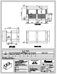
COMBINED<br />
BRACING/SCAFFOLDING/ALIGNMENT<br />
<strong>SYSTEM</strong><br />
<strong>DURISOL</strong> BUILDING <strong>SYSTEM</strong>S INC.<br />
REVISED:<br />
DRAWN BY:<br />
CHECKED BY:<br />
FILE NAME:<br />
FIGURE:<br />
SCALE:<br />
DWG. NO:<br />
DTG - 8a
Installation – Wall Form System �<br />
SET BRACES WITH THE <strong>WALL</strong> LEANING IN APPROX ½”. AFTER THE POUR, THE<br />
BRACES CAN BE TURNED TO PUSH THE <strong>WALL</strong> OUT AND INTO PLUMB ALIGNMENT.<br />
THIS IS PREFERABLE TO HAVING TO PULL THE <strong>WALL</strong> INTO ALIGNMENT<br />
THE BRACES ARE PRIMARILY REQUIRED FOR <strong>WALL</strong> ALIGNMENT – NOT TO<br />
PREVENT BLOWOUTS<br />
CONSULT LOCAL HEALTH AND SAFETY REQUIREMENTS FOR ADDITIONAL<br />
BRACING PRACTICES<br />
34
Installation – Wall Form System �<br />
2.13 Electrical Services and Wall Penetrations<br />
The <strong>Durisol</strong> Wall System easily accommodates electrical wiring and electrical service outlets. Surface<br />
grooves and outlet holes may be cut or drilled with ease using a router. The Wall Form surface<br />
material has sufficient depth to accommodate outlet boxes without the necessity to remove core<br />
concrete material. Alternately, electrical wires or conduits may be placed internally within the Wall<br />
Form cores prior to concrete placement.<br />
Wires in Surface Grooves Wires inside Cores<br />
Figure 2.12 – Electrical Service Installation<br />
Wires behind Drywall<br />
35
Installation – Wall Form System �<br />
Service Penetrations such as electrical conduits, water service pipes, air supply, and exhaust ducts<br />
can be easily placed by using a standard circular saw, reciprocating saw and/or hole saw. Simply use<br />
the saw to cut the Wall Form at the desired location and insert the appropriate service pipe or<br />
temporary blocking until the concrete is poured and hardened. The sleeve or conduit at the service<br />
penetration will create the void where services can be passed through later.<br />
If penetrations exceed 18” in either height or width, provide standard reinforcing around the opening<br />
in the same manner as window openings to prevent cracks from developing at the corners.<br />
CUT OUT THE <strong>DURISOL</strong> TO SHAPE SERVICE PENETRATIONS AND BLOCK OPENING<br />
TO PREVENT THE OPENING FROM FILLING WITH CONCRETE<br />
INSTALL PLATES AND CONNECTOR FOR EXTERIOR AND INTERIOR STRUCTURAL<br />
ATTACHMENTS (BRICK TIES, DECKS, PORCHES) PRIOR TO POURING CONCRETE<br />
CUT OUT <strong>DURISOL</strong> AND BLOCK OPENING FOR EXTERIOR FIXTURES<br />
CUT OUT <strong>DURISOL</strong> BLOCK OPENING FOR INTERIOR ATTACHEMENTS (CABINETRY<br />
ATTACHMENT POINTS)<br />
PREPARE DOOR OPENINGS (TRIM BLOCKS TO ALLOW DOORS TO OPEN GREATER<br />
THAN 90 DEGREES).<br />
INSTALL CHASES FOR PLUMBING AND SERVICES GREATER THAN 2”<br />
INSTALL ADDITIONAL BRACES (PLYWOOD) TO LOCATIONS OF CUT OUTS AND<br />
WHEREVER THE BLOCK HAS BEEN CUT AND THE WEB REMOVED<br />
ALWAYS MARK LOCATIONS ON <strong>WALL</strong> WHERE THE BLOCKS HAVE BEEN CUT AT THE<br />
TIME OF INSTALLATION. THIS WILL MAKE IT EASIER TO REMEMBER WHERE<br />
ADDITIONAL BRACING IS REQUIRED<br />
36
Installation – Wall Form System �<br />
2.14 Concrete Placement<br />
Prior to placing concrete in the <strong>Durisol</strong> Wall Forms, re-check the walls for plumb and make any<br />
adjustments necessary. Experience has shown that it is helpful to place a string line at the top<br />
perimeter of the wall to aid in adjusting the straightness of the wall prior to, during, and following<br />
placement of concrete into the Wall Forms.<br />
Refer to Fill Volume amounts contained in tables 1.2 – 1.5 for estimating concrete quantities. The Fill<br />
Volume in these tables is provided in units of yd 3 of concrete per ft 2 of wall surface area to be poured.<br />
The SI equivalent of this measure is m 3 of concrete per m 2 of wall area.<br />
All concrete placed within Wall Form units should be in accordance with applicable standards and<br />
codes (i.e. ACI 318 or ACI 332 in the USA and CSA A23.1 and CSA A438 in Canada). The concrete<br />
used with <strong>Durisol</strong> should have a minimum strength of 17 MPa (2500 psi) @ 28 days and a minimum<br />
slump of 175mm (7”). Maximum aggregate size should be 12mm (3/8”). High slump concrete and<br />
corresponding higher water to cement ratios are acceptable with <strong>Durisol</strong> Wall Forms because of the<br />
free-draining nature of the material. Once the concrete is placed within the forms, the water within the<br />
concrete immediately begins to drain through the <strong>Durisol</strong> material. This results in easier and faster<br />
concrete pouring that ensures a solid wall without voids and without any compromise in strength.<br />
Ideally, concrete with a slump between 7” and 9” is recommended for use in conjunction with <strong>Durisol</strong>.<br />
The insulating properties of <strong>Durisol</strong> Wall Forms allow winter construction without additional heating or<br />
insulation sources being required. <strong>Durisol</strong> wall systems have been constructed in temperatures as<br />
low as 22 �F (- 6�C) without any complication. When pouring in cold temperatures (i.e. less than 46�F<br />
or 8�C), the top of the walls must be covered with insulation so that the freshly poured concrete is not<br />
exposed to the cold.<br />
There are many methods of concrete placement that can be used with <strong>Durisol</strong> Wall Forms, including<br />
but not limited to, conveyor belts, concrete pumps, crane and bucket, by hand, or directly from truck<br />
chute. The concrete pump is typically the method of choice. Although initially more expensive, the<br />
extra cost of using a concrete pump will be offset by an easier construction process that results in<br />
faster overall construction and reduced labour costs. Placement of concrete by way of pumping<br />
should have a hose with a maximum exit nozzle size of 50mm to 80mm (2” – 3.5”). An elbow (“Shook”)<br />
at the bottom of the pump is required to slow the flow of concrete before it enters the Wall<br />
Form.<br />
Placement of concrete should typically begin by placing concrete below the window and door<br />
openings such that when the remainder of the wall is filled, a void is not created below the opening.<br />
Following this, the installer should then continue placing concrete into the remainder of the walls from<br />
the top and starting beside a window opening or not closer than 3’ to a corner. The concrete<br />
placement should continue around the building in lifts of not more than four feet per hour.<br />
37
Installation – Wall Form System �<br />
It is important to monitor the wall alignment relative to the string line installed prior to concrete<br />
placement. This will make the job of final alignment much simpler following concrete placement.<br />
As each layer of concrete is placed, care must be taken to ensure proper consolidation of the<br />
concrete and that the reinforcing bars are adequately embedded in concrete. Each successive lift<br />
must be properly consolidated with the previous pour to ensure that no cold joints occur. The most<br />
critical issue affecting the amount of consolidation that is required is the slump of the concrete mix<br />
being placed. A lower slump concrete will require additional work to properly consolidate the<br />
concrete. Consolidation is best accomplished by hand rodding in conjunction with a high slump<br />
concrete. This combination eliminates the unwanted additional form pressure that arises from using a<br />
vibrator. If a vibrator is used, the maximum diameter used should be no larger than 1-2” (25-50mm)<br />
and care must be taken to ensure the vibrator does not come into contact with the <strong>Durisol</strong> material.<br />
Once the concrete has been placed, make any final adjustments to the wall alignment to ensure a<br />
straight and plumb wall. If continuing <strong>Durisol</strong> above the present stage of construction, it is<br />
recommended that the initial placement of concrete stop 4” to 6” below the top the Wall Form with the<br />
surface left rough and unfinished to facilitate a better bond with subsequent lifts. Reinforcement<br />
required to bridge cold joints may be specified by shop drawings or by local codes.<br />
When the wall will not be continued for further stages of construction, the concrete will need to be<br />
finished at the top of the wall to provide a relatively smooth surface. Typically, the wall will have a<br />
wood plate installed in conjunction with anchor bolts to provide attachment for either floor joists, or<br />
roof trusses/rafters. Anchor bolts can be placed following finishing of the wall according to local<br />
building code requirements for anchorage.<br />
Before the fresh concrete has begun to cure, the wall should be rechecked for plumb and the<br />
necessary adjustments made.<br />
in the same manner as window openings to prevent cracks from developing at the corners.<br />
NEED AT LEAST 3 PEOPLE AT TIME OF POURING<br />
HAVE MATERIAL (BOARDS AND SCREWS) READY IN CASE OF BLOWOUT DUE TO<br />
MISSED BRACING REQUIREMENTS<br />
CALCULATE CONCRETE VOLUMES FROM TABLES IN SECTION 1 (ALSO ON<br />
WEBSITE)<br />
SPECIFY A “WET MIX” MINIMUM 7” – 8” SLUMP. SMALL AGGREGATE SIZE IS ALSO<br />
REQUIRED (3/8” MAX AGGREGATE).<br />
38
Installation – Wall Form System �<br />
TAKE CARE TO ENSURE NO VOIDS AT TIGHT LOCATIONS SUCH AS AROUND<br />
OPENINGS AND LINTELS. USE VIBRATOR AT THESE LOCATIONS IF DESIRED<br />
INSTALL CONCRETE ANCHORS / BASE PLATES<br />
CHECK PLUMBNESS OF <strong>WALL</strong> IMMEDIATELY AFTER POURING<br />
39
Interior Finishes – Wall Form System �<br />
3.0 INTERIOR FINISHES<br />
3.1 Gypsum Board<br />
The <strong>Durisol</strong> material provides a continuous solid surface for attaching interior finishes. Gypsum board<br />
can be applied directly to the <strong>Durisol</strong> material at any location on the surface of the wall. The hard and<br />
solid <strong>Durisol</strong> substrate provides support for the gypsum board and results in a durable and impact<br />
resistant finish. This is unlike conventional wall systems in which up to 88% of the wall surface behind<br />
the gypsum board is either open cavity, EPS or batt insulation, all of which provide little support for<br />
the drywall board and have potential to dent and/or break.<br />
Typically the sheet of gypsum board will be treated with conventional adhesive and screwed to the<br />
wall with coarse thread drywall screws. The following table outlines the different types of fasteners<br />
and their corresponding allowable pullout strengths while maintaining a minimum safety factor of 3.<br />
Table 3.1 – Fastener Types and Pull-out Loads<br />
Fastener Type Embedment Allowable Load (lbf)<br />
#6 x 2” Long<br />
Coarse thread drywall screw<br />
#6 x 2” Long<br />
Coarse thread drywall screw<br />
#8 x 3” Long<br />
Wood screw<br />
#12 x 3.5” Long<br />
Wood screw<br />
1 ¼ “ 33<br />
1 ¾ “ 37<br />
2 “ 52<br />
2 “ 47<br />
It is recommended that interior drywall be fastened directly to the <strong>Durisol</strong> Wall Form with standard #6<br />
x 2” long coarse threaded drywall screws as long as the following conditions are met:<br />
- Maximum spacing of fasteners is 16” in the body of the board<br />
- Maximum spacing of fasteners is 8” at the perimeter of the board<br />
- Conventional construction adhesive is employed at 4 corners and center of board<br />
- Caution is taken not to over drill and strip the <strong>Durisol</strong> material (i.e. use clutch drill).<br />
When choosing adhesives, ensure that they are compatible with the cement-based nature of <strong>Durisol</strong>.<br />
Contact your local adhesive supplier to ensure compatibility.<br />
Another option for fixing gypsum board is to use conventional furring strips that are adhered and<br />
screwed to the <strong>Durisol</strong> material.<br />
40
Interior Finishes – Wall Form System �<br />
3.2 Interior Plaster/Stucco<br />
The open textured nature of the <strong>Durisol</strong> material provides an ideal substrate for stuccos and plasters.<br />
Two or three coat applications of plaster work particularly well with no special pretreatment of metal<br />
lathe or glass fiber reinforcing being required. When transitioning from dissimilar materials (such as<br />
from wood to <strong>Durisol</strong>, concrete to wood, etc) additional reinforcing may be required. It is also<br />
recommended that conventional loose reinforcing fibers be added to the base coat mix to minimize<br />
and control cracking of the first coat. Consult your plaster supplier and installer for information<br />
regarding the types and quantities of fiber that are generally utilized.<br />
It is important to account for the rough, porous nature of <strong>Durisol</strong> when estimating finish material<br />
quantities. The quantity of base coat material required is approximately 25% higher than that required<br />
for conventional concrete masonry. Subsequent coats applied to the base coat will utilize the same<br />
amount of material as when used with other conventional wall types such as masonry and wallboard.<br />
For further information, please refer to the separate document outlining the guidelines for using<br />
plaster and stucco with <strong>Durisol</strong>.<br />
3.3 Other Interior Finishes<br />
Any finish material can be used with the <strong>Durisol</strong> wall system. It is important however to consult the<br />
finish material manufacturer’s installation instructions and specifications and follow all recommended<br />
procedures to ensure compatibility with <strong>Durisol</strong> (i.e. cement-based substrates).<br />
41
Exterior Finishes – Wall Form System �<br />
4.0 EXTERIOR FINISHES<br />
The <strong>Durisol</strong> material is a very durable and weather resistant material and as such can be left exposed<br />
without any damage occurring to the material itself. However, since the <strong>Durisol</strong> material is extremely<br />
porous and free-draining, it is important to provide an adequate weather/moisture/air barrier on the<br />
exterior surface of <strong>Durisol</strong> walls in applications where the interior environment must be controlled and<br />
protected from moisture and weather.<br />
4.1 Below-Grade Waterproofing<br />
Below-Grade Waterproofing is not required for foundation stem walls or other applications where the<br />
inside of the wall does not need to be completely dry (equipment storage buildings, etc.).<br />
There are many waterproofing products available for basement and other below-grade walls. All<br />
conventional waterproofing systems have been successfully used in conjunction with <strong>Durisol</strong>.<br />
Typically a cement based parge coat is first applied to the below grade <strong>Durisol</strong> wall surface. The base<br />
coat is a simple mixture of sand, cement and water (usually 3 parts sand and 1 part cement) that is<br />
applied to the <strong>Durisol</strong> surface to achieve the following purposes:<br />
- It completely seals the exterior surface (air barrier)<br />
- It provides a smooth inexpensive substrate for the next waterproofing layer. By using a parge<br />
coat first, the quantity of waterproofing material is reduced which in turn reduces overall costs.<br />
Depending on the soil conditions, alternate air barrier system and water protection systems<br />
employed, it is possible to substitute the parge coat with other materials or remove the parge coat<br />
altogether. This should be done only at the explicit design and instruction of the designer. It is<br />
always recommended to first apply a cement based parge coat that is followed by other moisture<br />
protection systems. The minimal extra cost of this first layer will provide considerable added<br />
protection from moisture and increase the redundancy of the waterproofing system.<br />
The other waterproofing products applied to the base coat include (but are not limited to) the<br />
following:<br />
- Bitumen-type roll applied damproofing and other “Tar” type materials<br />
- Adhesive backed membranes (”Peel ‘n’ Stick”)<br />
- Drainage layer / Air Gap membranes (Delta MS, Mira-drain, etc.)<br />
The <strong>Durisol</strong> recommended method of waterproofing is employing a combination of a standard cement<br />
parge coat that is followed by the bitumen-based “tar” product or other membrane type of<br />
waterproofing. As an added protection, we also recommend the use of the drainage layer type of<br />
membrane. This combination of systems provides a redundant waterproofing system that will ensure<br />
a moisture-free environment when installed properly.<br />
42
Exterior Finishes – Wall Form System �<br />
Please consult the waterproofing product manufacturer for installation procedures when applying their<br />
product to a cement-based parge layer (usually the same as procedure as for typical masonry<br />
foundation walls).<br />
<strong>DURISOL</strong> CAN PROVIDE MEMBRANE WATERPROOFING AND VAPOUR PERMEABLE<br />
AIR BARRIER <strong>SYSTEM</strong>S WITH YOUR ORDER.<br />
WATERPROOFING OPTION 1 – STUCCO PARGE, ROLL-ON WATERPROOFING,<br />
DIMPLE SHEET<br />
WATERPROOFING OPTION 2 – PEEL-N-STICK MEMBRANE (USE PRIMER ON<br />
<strong>DURISOL</strong> FIRST), EITHER DIMPLE SHEET OR INSULATION TO PROTECT MEMBRANE<br />
4.2 Above-Grade Finishes<br />
4.2.1 ACRYLIC BASED COATINGS<br />
Acrylic based coatings are used extensively in North America. A typical EIFS (exterior insulated<br />
finish system) system would consist of a wood or masonry wall system that is followed by a layer<br />
of EPS foam and then finished with the acrylic based stucco that contains a woven fiberglass<br />
mesh that is embedded in the base coat. Since the <strong>Durisol</strong> wall system provides the integral<br />
insulation, no additional EPS is required on the exterior surface. There are many vapour<br />
permeable (i.e. breathable) acrylic coatings available that will not compromise the performance of<br />
the <strong>Durisol</strong> wall system with respect to water vapour movement.<br />
In all circumstances, it is important to follow the EIFS manufacturers recommendations for<br />
application of their system to the <strong>Durisol</strong> wall surface. This will ensure proper moisture protection,<br />
eliminate possible defects in the finished installation and guarantee that any warranties offered by<br />
the EIFS manufacturer remain valid.<br />
When compared to conventional masonry, the rough, porous nature of <strong>Durisol</strong> results in<br />
25% more base coat material being required per square foot of wall surface area.<br />
Subsequent coats applied to the base coat will utilize the same amount of material as when used<br />
with other conventional walls such as masonry.<br />
For further information, please refer to the separate document outlining the guidelines for using<br />
plaster and stucco with <strong>Durisol</strong>.<br />
FOLLOW EIFS MANUFACTURER REQUIREMENTS FOR ACRYLIC STUCCO<br />
<strong>SYSTEM</strong>S.<br />
43
Exterior Finishes – Wall Form System �<br />
4.2.2 TRADITIONAL NON-ACRYLIC STUCCO<br />
Unlike the acrylic systems, cement-based and other natural stuccos are extremely dependent on<br />
the following:<br />
- Weather conditions at the time application<br />
- Quality of workmanship<br />
- Weather conditions and curing procedures after application<br />
- Preparation of the surface prior to stucco application<br />
It is recommended that traditional cement-based stuccos be used only by experienced, qualified<br />
installers who are aware of the implications of the above three items on the performance of the<br />
final exterior finish. Consult the installer or material supplier for mix design ratios. The following<br />
precautions must be taken with all stucco finishes:<br />
1. Careful consideration of whether a moisture barrier is required behind the stucco. The <strong>Durisol</strong><br />
is porous and will require a moisture barrier behind the stucco (ex. Paper-backed lath)<br />
depending on the region (windy/wet locations) and site specific locations (high elevations,<br />
building orientation, etc). If there is any concern regarding moisture protection, it is always<br />
recommended to incorporate a moisture barrier over the <strong>Durisol</strong> prior to applying stucco.<br />
2. When the <strong>Durisol</strong> material is wet, prior to stucco application, it can expand as much as 0.3%<br />
(3mm per 1000mm). As the material dries out, shrinkage of the <strong>Durisol</strong> material will cause<br />
the base coat to crack at the Wall Form joints. This cracking must be allowed to occur and<br />
sufficient time must be allowed to let the <strong>Durisol</strong> material completely dry out prior to applying<br />
subsequent coats. The second and third coats are applied to the base coat material that is<br />
only slightly wetted so that the <strong>Durisol</strong> material does not expand and contract too severely.<br />
3. The <strong>Durisol</strong> surface should be inspected and prepared prior to applying stucco. The ultimate<br />
demand for a truly level plaster base is very important because projecting blocks, stones or<br />
plates cause irregular plaster thicknesses that are prone to a higher risk of crack formation.<br />
The same applies to joints between blocks that are not at all or only partly filled. Joints that<br />
are greater than 5 mm (0.2 in) have to be filled with an appropriate material so that they are<br />
flush. At these joints, the plaster forms a bridge across the open joint. The slightest thermal<br />
changes (movement, tension) in the plaster base will cause the plaster to crack. Prior to<br />
plastering or precoating, wall surfaces need to be cleaned, any loose pieces need to be<br />
removed and replaced with an appropriate material.<br />
4. All stuccos should have reinforcing included in the stucco to minimize cracking in the finish.<br />
Both loose fiber reinforcement (polypropylene or glass - typical ½” - ¾“ fiber) added to the<br />
basecoat and/or manufactured woven fiberglass mesh (manufactured by Dryvit or equivalent)<br />
troweled into the base coat may be used (see options below). Conventional self-furring<br />
44
Exterior Finishes – Wall Form System �<br />
paperbacked expanded metal lath can be used if lath is attached to <strong>Durisol</strong> with coarse<br />
thread screws at maximum 8” spacing, and care is taken not to overdrill the screws or strip<br />
the <strong>Durisol</strong> material. For further information, please refer to the separate document outlining<br />
the guidelines for using plaster and stucco with <strong>Durisol</strong>.<br />
5. Woven fiberglass mesh (6oz glass fiber per ft 2 typical) should be employed in addition to the<br />
loose fibermesh fibers in all thermal Wall Forms incorporating insulation inserts. These rolls<br />
are the same as used in conventional EIFS systems and are available wherever systems<br />
such as Dryvit, Sto, or similar systems are found. Consult the stucco applicator or material<br />
supplier for detailed information and specifications for the woven fiberglass mesh.<br />
6. The stucco should be applied in layers not greater than 3/8” thick and must be allowed to<br />
cure properly in order to avoid the occurrence of significant cracks and joint telegraphing. As<br />
you progress from the base coat to the finish coat, each layer should become progressively<br />
weaker/softer. The base coat should be the stiffest/hardest coat, while the finish coat should<br />
be the weakest/softness coat. This is done to minimize the potential for cracking. For further<br />
information, please refer to the separate document outlining the guidelines for using plaster<br />
and stucco with <strong>Durisol</strong>.<br />
7. Acrylic additives should also be considered for use with each layer of stucco that is applied to<br />
<strong>Durisol</strong>. In right proportions, these additives increase stucco elasticity and minimize dryshrinkage<br />
cracks without compromising the vapour permeability of the wall system.<br />
For further information, please refer to the separate document outlining the guidelines for using<br />
plaster and stucco with <strong>Durisol</strong><br />
NOTE:<br />
All information contained in this manual is for general information purposes only. Consult local<br />
installers and suppliers of finish material as well as association guidelines (ex. Portland Cement<br />
Association guidelines for stucco finishes). Procedures will vary between areas and<br />
consideration must be made to items such moisture conditions, exterior/interior temperatures,<br />
exposure to wind/drying, etc. It is always the installer’s responsibility to ensure quality installation<br />
of all finishes.<br />
LIME STUCCOS (SAND + LIME ONLY) ARE MORE ELASTIC THAN CEMENT STUCCOS.<br />
THERE IS A DIFFERENCE BETWEEN HYDRAULIC LIME AND NON-HYDRAULIC LIME.<br />
ALWAYS CONSULT AN EXPERT WHEN USING NATURAL STUCCOS AND PLASTERS<br />
THE LIME USED FOR LIME MORTAR IS NOT ALWAYS THE RIGHT LIME FOR<br />
STUCCOS AND PLASTERS.<br />
UNLESS YOU HAVE EXPERIENCE AND KNOWLEDGE OF LIME STUCCOS AND MIX<br />
DESIGNS, IT IS RECOMMENDED TO USE SPIDERLATH MESH OVER THE <strong>DURISOL</strong><br />
TO ENSURE NO CRACKING.<br />
45
Exterior Finishes – Wall Form System �<br />
4.2.3 MASONRY VENEER<br />
Masonry veneer installed against a <strong>Durisol</strong> wall must be installed in full accordance with local<br />
building codes. This includes proper flashing details at the base of the veneer and around all<br />
window and door openings as well as other penetrations through the wall. Standard weep holes<br />
must also be provided as required by code.<br />
Because the <strong>Durisol</strong> material is susceptible to deflection under long-term loading, masonry<br />
veneer cannot be erected directly on top of the <strong>Durisol</strong> material. All veneers must be<br />
supported by solid concrete only. Depending on the wall thickness above and below the start<br />
of the masonry veneer, three methods of accommodating the veneer are possible (see drawings<br />
on following pages):<br />
1. The first method is used when <strong>Durisol</strong> is employed as foundation walls and not continued<br />
behind the masonry veneer, or when a smaller <strong>Durisol</strong> Wall Form is used behind the<br />
masonry veneer. In these situations the tapered <strong>Durisol</strong> Wall Form (i.e. DL) can be<br />
installed to provide a complete concrete bearing thickness of 8, 10 or 12” (i.e. the full<br />
width of the Wall Form).<br />
2. If the <strong>Durisol</strong> wall system is to be continued behind the masonry veneer, a brick ledge<br />
must be created on the exterior of the Wall Form. These brick ledges may be formed and<br />
poured integrally with the <strong>Durisol</strong> wall system at the time of wall construction. There are a<br />
variety of products available as brick ledge forms that are manufactured specifically for<br />
the ICF industry. Alternately, conventional forming techniques can be utilized to create<br />
the brick ledge.<br />
3. The third method of accommodating masonry veneer is using a conventional steel angle<br />
that is anchored into the concrete within the <strong>Durisol</strong> Wall Form. The angle is installed<br />
after the wall has been constructed and the concrete has cured. Angle sizes as well as<br />
anchor bolt size and spacing must be designed and specified by a local design<br />
professional.<br />
USE ICF MASONRY TIES THAT ARE EMBEDDED IN THE CONCRETE CORES PRIOR<br />
TO POURING THE CONCRETE<br />
46
Exterior Finishes – Wall Form System �<br />
4.2.4 SIDING<br />
When siding is used in conjunction with the <strong>Durisol</strong> wall system, it is recommended that strapping<br />
first be attached to the <strong>Durisol</strong> wall surface. Strapping material can be fastened to the <strong>Durisol</strong><br />
material using a number of approved methods. Our tests have shown that a #8 deck screw<br />
embedded 1 ¾” into the <strong>Durisol</strong> material has maximum pull out load of 110lbs. This translates to<br />
a design pullout load of 55lbs per fastener when incorporating a safety factor = 2. The following<br />
spacing requirements are based on wind speed = and a corresponding design load of<br />
Option 1 – Strapping is in direct contact with exterior <strong>Durisol</strong> Material<br />
If the strapping is applied directly to the <strong>Durisol</strong> material, it is assumed that there will be a<br />
weather/air barrier applied over the <strong>Durisol</strong> material in between the strapping lines (either spray<br />
applied, parging, etc). In this case, using fasteners in conjunction with conventional construction<br />
adhesive (ex. PL Premium adhesive by LePage) is best. Apply the construction adhesive to the<br />
back of the strapping and secure the strapping to the <strong>Durisol</strong> material using #8 exterior grade<br />
deck screws or equivalent. There should be at least 1 screw per 3 sq ft of wall area. For example,<br />
if the strapping is placed at 24” spacing, the screws should be spaced at 18” o/c maximum along<br />
the length of the strap. Screws should embed into the <strong>Durisol</strong> material a minimum of 1 ¾”. Care<br />
should be taken to ensure the screws are not overdrilled – otherwise the <strong>Durisol</strong> material can strip<br />
and there will be no pullout strength. If this does occur, simply use a second screw 3” away from<br />
the stripped screw location.<br />
Option 2 – Strapping is applied over a weather barrier (tyvek, building paper, etc)<br />
If there is a weather barrier between the strapping and the <strong>Durisol</strong> material, only fasteners are<br />
used to attach the strapping (adhesive will not provide any additional strength). In this case,<br />
remove a small portion of the weather barrier behind the strapping every 3ft and secure the<br />
strapping directly to the <strong>Durisol</strong> with adhesive. Also secure the strapping to the <strong>Durisol</strong> material<br />
(through the weather barrier) using #8 exterior grade deck screws or equivalent. There should be<br />
at least 1 screw per 1.5 sq ft of wall area. For example, if the strapping is placed at 24” spaces,<br />
the screws should be spaced at 9” o/c maximum along the length of the strap. Screws should<br />
embed into the <strong>Durisol</strong> material a minimum of 1 ¾”. Care should be taken to ensure the screws<br />
are not overdrilled – otherwise the <strong>Durisol</strong> material can strip and there will be no pullout strength<br />
to the fastener. If this does occur, simply use 2 additional screws 2” - 3” away in both directions<br />
from the stripped screw location.<br />
SIDING OPTION 1 – STRAPPING OVER <strong>DURISOL</strong> AND THEN WEATHER AIR BARRIER<br />
IN BETWEEN STRAPPING. USE COMBINATION OF ADHESIVE AND #8 SCREWS TO<br />
ATTACH STRAPPING<br />
SIDING OPTION 2 – WEATHER BARRIER OVER <strong>DURISOL</strong> AND THEN STRAPPING<br />
OVER WEATHER BARRIER. REMOVE 1.5” SQUARE OF WEATHER BARRIER BEHIND<br />
STRAPPING EVERY 36” AND USE ADHESIVE TO MECHANICALLY BOND STRAPPING<br />
TO THE <strong>DURISOL</strong> MATERIAL. USE #8 SCREWS TO SCREW DIRECTLY TO THE<br />
<strong>DURISOL</strong> AS WELL.<br />
50
Air-Vapour Barriers – Wall Form System �<br />
5.0 AIR-VAPOUR BARRIER REQUIREMENTS<br />
There is considerable confusion in the building industry regarding air barriers, vapour barriers and their<br />
respective purposes. The function of a vapour barrier is to prevent moisture and condensation related<br />
deterioration of the wall assembly. The function of an air barrier is to prevent heat loss and maintain<br />
energy efficiency.<br />
The polyethylene sheet commonly found on the interior of a conventionally framed wall system serves<br />
both as an air barrier and a vapour barrier, further confusing the function of the two barriers and their<br />
required location within the wall assembly. A vapour barrier is required on the interior of the insulation to<br />
prevent the warm moisture laden interior air from traveling through the insulation, to the cool side and<br />
condensing within the wall. This is based on winter conditions and a corresponding outward vapour drive.<br />
Since the polyethylene sheet serves as both the air barrier and vapour barrier, it is placed on the interior<br />
surface to satisfy the requirements for the vapour barrier function. Problems can still occur in this<br />
assembly, however, when exterior temperatures are warmer and more humid (summer conditions),<br />
resulting in the potential for an inward vapour drive and moisture still condensing within the wall system.<br />
The <strong>Durisol</strong> wall assembly will typically have a permeance ranging between 40 – 150 ng/(Pa.s.m 2 ),<br />
depending on interior and exterior finishes. This is a more vapour permeable wall system than<br />
conventional construction. This vapour permeability can actually contribute to improved indoor air quality<br />
by providing for more dynamic humidity control - when used in conjunction with hygric mass materials<br />
(such as <strong>Durisol</strong>) and wall components that are not adversely affected by moisture (materials such as<br />
concrete and <strong>Durisol</strong>). This buffering effect is beneficial in reducing large humidity fluctuations within the ,<br />
by not incorporating a vapour barrier with the <strong>Durisol</strong> system.<br />
The purpose of an air barrier is simply to prevent air flow through the wall. The location of the air barrier<br />
within the wall assembly is not important since the air barrier function is not related to RH and the<br />
potential for condensation. As long as the air can not move through the wall, there will be no<br />
corresponding heat loss due to air flow, and energy efficiencies are maintained. Consequently, for this<br />
purpose, the air barrier can be on the interior or exterior face of the walls system, or even within the wall<br />
system itself.<br />
Integral to the desired performance of the <strong>Durisol</strong> wall system is the inclusion of a continuous air barrier.<br />
The majority of thermal performance problems and related moisture / condensation problems, occur as a<br />
result of air leakage and not vapour diffusion. The <strong>Durisol</strong> wall assembly, by itself does not serve as an<br />
adequate air barrier and one must be incorporated into the wall assembly. This is typically achieved, by<br />
one of the following methods:<br />
- Continuous cement basecoat (Parge coat) applied to the exterior surface of the <strong>Durisol</strong> material<br />
- Continuous multiple coat exterior stucco systems (synthetic or natural stucco).<br />
- Exterior applied air membrane products<br />
- Exterior building wrap products<br />
- Interior airtight drywall approach (ADA)<br />
- Any other system as outlined by applicable building codes<br />
53
Air-Vapour Barriers – Wall Form System �<br />
The following is a list of typical finishes and the corresponding recommended air barriers:<br />
Exterior Cladding Recommended Air Barrier System<br />
Brick Veneer Separate air barrier system within air space between <strong>Durisol</strong><br />
and Veneer. Acceptable air barriers are stucco, parge coat,<br />
building paper/wrap, membrane products or any other system<br />
meeting the requirements of 2006 OBC air barrier systems.<br />
Exterior Stucco Stucco is an acceptable air barrier itself and no additional air<br />
barrier system is required.<br />
Siding Separate air barrier system within air space between <strong>Durisol</strong><br />
and Siding. Acceptable air barriers are stucco, parge coat,<br />
building paper/wrap, membrane products or any other system<br />
meeting the requirements of 2006 OBC air barrier systems.<br />
Other exterior finish If the exterior finish can not be shown to act as an adequate<br />
air barrier, a separate air barrier system is required between<br />
the <strong>Durisol</strong> and exterior finish. Acceptable air barriers are<br />
stucco parge coat, building paper/wrap, membrane products<br />
or any other system meeting the requirements of 2006 OBC<br />
air barrier systems.<br />
There may be special applications where an interior air barrier is preferable to an exterior air barrier.<br />
This is acceptable as long as it has been reviewed and accepted by a licensed professional engineer<br />
or architect.<br />
54