7 Light and Geometric Optics - BC Science Physics 11
7 Light and Geometric Optics - BC Science Physics 11
7 Light and Geometric Optics - BC Science Physics 11

You also want an ePaper? Increase the reach of your titles
YUMPU automatically turns print PDFs into web optimized ePapers that Google loves.
7 <strong>Light</strong> <strong>and</strong> <strong>Geometric</strong> <strong>Optics</strong><br />
By the end of this chapter, you should be able to do the following:<br />
➢ Use ray diagrams to analyse situations in which light<br />
reflects from plane <strong>and</strong> curved mirrors<br />
• state the law of reflection<br />
• identify the following on appropriate diagrams:<br />
– incident ray<br />
– reflected ray<br />
– angle of incidence<br />
– angle of reflection<br />
– normal<br />
• show how an image is produced by a plane mirror<br />
• describe the characteristics of an image produced<br />
by a plane mirror<br />
• identify a curved mirror as converging (concave) or<br />
diverging (convex)<br />
• identify the following on appropriate diagrams:<br />
– principal axis<br />
– centre <strong>and</strong> radius of curvature<br />
– image <strong>and</strong> object distance<br />
– focal point <strong>and</strong> focal length<br />
• draw accurate scale diagrams for both concave <strong>and</strong><br />
convex mirrors to show how an image is produced<br />
• describe the characteristics of images produced by<br />
converging <strong>and</strong> diverging mirrors<br />
• conduct an experiment to determine the focal<br />
length of a concave mirror<br />
By the end of this chapter, you should know the meaning to these<br />
key terms:<br />
• angle of incidence<br />
• angle of reflection<br />
• concave<br />
• convex<br />
• converging lens<br />
• diverging lens<br />
• electromagnetic radiation<br />
• electromagnetic spectrum<br />
• focal point<br />
• image distance<br />
• incident ray<br />
• law of reflection lens<br />
• mirror equation<br />
• normal<br />
• object distance<br />
• polarization<br />
• principal focus<br />
• real image<br />
• reflected ray<br />
• refraction<br />
• refractive index<br />
• Snell’s Law<br />
• virtual image<br />
By the end of the chapter, you should be able to use <strong>and</strong> know<br />
when to use the following formulae:<br />
1<br />
d i<br />
+ 1<br />
=<br />
do 1<br />
f<br />
c<br />
n =<br />
v<br />
➢ Analyse situations in which light is refracted<br />
• identify the following from appropriate diagrams:<br />
– incident ray – angle of incidence<br />
– refracted ray – angle of reflection<br />
– normal<br />
• use Snell’s law to solve a range of problems<br />
involving:<br />
– index of refraction – angle of incidence<br />
– angle of reflection<br />
• define critical angle <strong>and</strong> total internal reflection<br />
• solve problems involving critical angles<br />
• identify a lens as converging (convex) or diverging<br />
(concave)<br />
• for a lens, identify the following from appropriate<br />
diagrams:<br />
– principal axis<br />
– focal point (primary <strong>and</strong> secondary)<br />
– focal length<br />
– image <strong>and</strong> object distance<br />
• draw accurate scale diagrams for both convex <strong>and</strong><br />
concave lenses to show how an image is produced<br />
• describe the characteristics of images produced by<br />
converging <strong>and</strong> diverging lenses<br />
• conduct an experiment to determine the focal<br />
length of a convex lens<br />
n 1 sin(θ i ) = n 2 sin(θ r ) In this chapter you’ll learn how lenses can help<br />
you see things differently.<br />
© Edvantage Interactive 2012 ISBN 978-0-9864778-3-6 Chapter 7 <strong>Light</strong> <strong>and</strong> <strong>Geometric</strong> <strong>Optics</strong> 199
7.1 Re�ection<br />
Warm Up<br />
Make a pinhole camera with a Styrofoam or paper cup. Place<br />
a square of wax paper over the open end of the cup <strong>and</strong> hold<br />
it in place with a rubber b<strong>and</strong>. With a pin, poke a small hole<br />
in the other end of the cup. In a dark room with a light bulb<br />
at one end, observe the image formed on the wax paper.<br />
Make sure the pinhole faces the light. Describe the image.<br />
__________________________________________________<br />
_____________________________________________________________________________________________<br />
_____________________________________________________________________________________________<br />
_____________________________________________________________________________________________<br />
Properties of <strong>Light</strong><br />
The Electromagnetic<br />
Spectrum<br />
���������������<br />
�������������<br />
����������<br />
������������<br />
��������������<br />
����<br />
�����<br />
�������<br />
����<br />
����������<br />
���<br />
�������<br />
Many useful devices have been developed because of growing knowledge of how light<br />
behaves. One can describe many of the properties of light without knowing exactly what<br />
light is, <strong>and</strong> one can invent many devices that use these properties. Cameras, eyeglasses,<br />
mirrors, microscopes, periscopes, magnifying glasses, spectroscopes <strong>and</strong> various kinds of<br />
projectors are some of the optical devices that use well-known properties of light. In this<br />
chapter, you will investigate some of the important properties of light.<br />
<strong>Light</strong> is a form of electromagnetic radiation. Electromagnetic radiation is radiant<br />
energy that travels at the speed of light (300 000 km/s). Figure 7.1.1 shows the different<br />
forms of electromagnetic radiation that occur in nature. All the different forms together<br />
make up the electromagnetic spectrum. A key property of all forms of radiation is the<br />
wavelength-frequency-energy relationship. Figure 7.1.1 shows radiation such as AM<br />
radio having long wavelength, low frequency, <strong>and</strong> low energy. At the other end of the<br />
spectrum, X-rays have short wavelengths, high frequency, <strong>and</strong> high energy.<br />
��<br />
�����<br />
���������<br />
�����<br />
Figure 7.1.1 The electromagnetic spectrum<br />
������<br />
��������<br />
���������<br />
�����<br />
��������<br />
�����<br />
�������<br />
�����������<br />
�����<br />
����������������<br />
��������������<br />
�����������<br />
������ ����������<br />
200 Chapter 7 <strong>Light</strong> <strong>and</strong> <strong>Geometric</strong> <strong>Optics</strong> © Edvantage Interactive 2012 ISBN 978-0-9864778-3-6
Table 7.1.1 Major Forms of Electromagnetic Radiation<br />
Long wavelength<br />
Low frequency<br />
Low energy<br />
Short wavelength<br />
High frequency<br />
High energy<br />
Table 7.1.1 outlines the major forms of radiation found in the electromagnetic<br />
spectrum. Within this whole spectrum of radiation, visible light is a tiny slice of all the<br />
possible forms of radiation.<br />
Form Frequency Wavelength Description<br />
Aircraft <strong>and</strong><br />
shipping b<strong>and</strong>s<br />
10 2 –10 4 Hz 10 4 –10 6 m<br />
AM radio 10 6 Hz 1000 m<br />
Shortwave radio 10 7 Hz 100 m<br />
TV <strong>and</strong> FM radio 10 8 Hz 1 m<br />
Microwave <strong>and</strong><br />
radar<br />
10 12 Hz 0.01 m<br />
Infrared light 10 12 –10 14 Hz 0.001 m<br />
Visible light 10 15 Hz 10 −6 m<br />
Ultraviolet light 10 15 –10 17 Hz 10 −7 m<br />
X-rays 10 17 –10 21 Hz 10 −9 –10 −13 m<br />
Gamma rays 10 19 –10 21 Hz 10 −10 –10 −13 m<br />
Long waves used for aircraft <strong>and</strong><br />
shipping communications<br />
Radio waves used for sound<br />
broadcasting over short distances<br />
Radio waves used for sound<br />
broadcasting over long distances<br />
(around the world)<br />
Radio waves used for sound <strong>and</strong><br />
image broadcasting<br />
Radio waves that can penetrate the<br />
Earth’s atmosphere, making them<br />
ideal for satellite communication;<br />
short wavelengths so can be reflected<br />
off distant objects; also used in<br />
cooking.<br />
Radiation emitted from hot objects;<br />
the higher the temperature, the more<br />
infrared radiation emitted<br />
Radiation observable by the human<br />
eye<br />
Radiation from the Sun <strong>and</strong> humanmade<br />
devices such as mercury vapour<br />
lamps; gives humans tans; stimulates<br />
vitamin D production in the skin<br />
Two types used: long-wavelength<br />
X-rays used in medicine to penetrate<br />
skin (do not go through bone); shortwavelength<br />
X-rays used in industry to<br />
inspect metal for faults<br />
Produced when protons <strong>and</strong><br />
neutrons in the nucleus of an atom<br />
are rearranged; used in medicine; kill<br />
bacteria in food<br />
Example of<br />
Object of<br />
Similar Size<br />
© Edvantage Interactive 2012 ISBN 978-0-9864778-3-6 Chapter 7 <strong>Light</strong> <strong>and</strong> <strong>Geometric</strong> <strong>Optics</strong> 201<br />
Earth<br />
kilometre<br />
soccer field<br />
metre stick<br />
centimetre<br />
millimetre<br />
dust particle<br />
DNA<br />
molecule<br />
atom<br />
nucleus
Visible <strong>Light</strong><br />
Wavelengths We Use<br />
But Cannot See<br />
Wavelengths of visible light range from<br />
3.8 × 10 –7 m for violet light to 7.6 × 10 –7 m for<br />
red light. Wavelengths are often expressed in<br />
nanometres (nm), where 1 nm = 10 –9 m.<br />
Table 7.1.2 lists some typical wavelengths in<br />
the visible range.<br />
It is interesting to note that if your eye<br />
detects light in the range of wavelengths<br />
between 560 nm <strong>and</strong> 590 nm, it perceives<br />
the light as yellow. If, however, it sees a mix of<br />
colours, one in the range between 630 nm <strong>and</strong><br />
760 nm (red) <strong>and</strong> the other between 490 nm <strong>and</strong><br />
560 nm (green), it again perceives the light as<br />
being yellow!<br />
Table 7.1.2 Wavelengths of Visible <strong>Light</strong><br />
Colour Range of wavelengths<br />
red 630–760 nm<br />
orange 590–630 nm<br />
yellow 560–590 nm<br />
green 490–560 nm<br />
blue 450–490 nm<br />
violet 380–450 nm<br />
If a beam of white light is dispersed with a prism, <strong>and</strong> the spectrum is viewed on screen,<br />
you will see all the colours from violet to red on the screen. In the early nineteenth<br />
century, the English astronomer William Herschel (1738–1822) was experimenting to<br />
see which colours of light gave the greatest heating effect when allowed to shine on<br />
the blackened bulb of a thermometer. He moved the thermometer bulb through the<br />
various parts of the visible spectrum <strong>and</strong> observed increases in temperature caused by<br />
the different colours of light. He discovered to his surprise that the greatest heating effect<br />
was observed if the bulb was placed beyond the red end of the visible spectrum! This is<br />
how infrared radiation was discovered.<br />
Infrared radiation is extremely important to us. Infrared radiation from the Sun<br />
provides most of the thermal energy requirements of the planet. Scientists have<br />
developed infrared photographic techniques that permit satellite pictures of features<br />
on the Earth’s surface, which can be taken through clouds, fog, or smoke. Objects can<br />
be photographed in the dark using infrared photography. Some auto focus cameras<br />
use infrared for focussing, which means they work in the dark. Infrared has many uses,<br />
including heat lamps, physiotherapy, <strong>and</strong> medical diagnostic photography. Astronomers<br />
are now making good use of infrared images of the stars <strong>and</strong> other objects in the<br />
universe.<br />
Infrared wavelengths cover a wide range, the shortest wavelength beginning<br />
at the red end of the visible spectrum (760 nm) <strong>and</strong> the longest wavelength being<br />
approximately 300 000 nm. Beyond the infrared lies the radio part of the spectrum.<br />
In 1801, the German physicist, Johann Wilhelm Ritter (1776–1810), was studying the<br />
effect of visible light on the chemical compound silver chloride, AgCl. When light falls on<br />
silver chloride, the white compound decomposes <strong>and</strong> forms silver, which appears black,<br />
<strong>and</strong> chlorine, which escapes into the atmosphere. This is similar to the chemical reaction<br />
for photographic film development where silver bromide is used.<br />
Ritter knew that the effect was most noticeable at the violet end of the spectrum.<br />
He was surprised to find that if silver chloride was placed in a region beyond the violet<br />
end of the visible spectrum, the decomposition of the silver chloride was even more<br />
pronounced! Thus, ultraviolet radiation was discovered.<br />
You cannot see ultraviolet, but it is wise to know about it anyway. It is ultraviolet<br />
light that gives you a suntan or sunburn. Too much exposure to the Sun or to ultravioletrich<br />
sunlamps can be dangerous. Ultraviolet can also damage parts of your retina, thus<br />
impairing your vision.<br />
202 Chapter 7 <strong>Light</strong> <strong>and</strong> <strong>Geometric</strong> <strong>Optics</strong> © Edvantage Interactive 2012 ISBN 978-0-9864778-3-6
Linear Propagation<br />
of <strong>Light</strong><br />
The Law of<br />
Re�ection<br />
“Black lights,” sold to make posters fluoresce, are actually sources of ultraviolet light.<br />
They also give off light in the violet part of the spectrum. Some black lights are essentially<br />
mercury vapour lamps, like fluorescent lamps used to light your classroom. Instead of<br />
having an inner coating of fluorescent chemicals, they have a violet-coloured glass tube<br />
that allows violet <strong>and</strong> ultraviolet light to pass through it.<br />
<strong>Light</strong> travels in straight lines ⎯ sometimes. Over short distances, in a given medium<br />
such as air or water, light travels in a straight path. If light encounters a different medium<br />
or a reflecting surface, its path will change. Gravity can also deflect light from a straight<br />
path. Einstein predicted this long ago, <strong>and</strong> experiments verified his prediction. In most<br />
situations you will encounter, however, you may assume that the path of light in a given<br />
medium is straight. You can predict the size <strong>and</strong> shape of shadows by assuming linear<br />
propagation of light.<br />
When drawing pictures involving light, a straight arrow called a ray is used to<br />
represent the light. This type of diagram is called a ray diagram. Figure 7.1.2(a) shows a<br />
ray of light coming from the top of the c<strong>and</strong>le <strong>and</strong> moving toward a mirror. For you to see<br />
the image of this c<strong>and</strong>le in the mirror, the light needs to be reflected back to your eye.<br />
Another ray pointed in the other direction illustrates this situation. This completes the ray<br />
diagram (Figure 7.1.2(b)).<br />
������ ������ ������ ������<br />
(a) Draw the ray from the object to the mirror. (b) Draw the reflected ray back to the eye.<br />
Figure 7.1.2 Drawing a ray diagram<br />
If you look directly into a mirror <strong>and</strong> wink<br />
your left eye, which eye will your image<br />
wink? Now look at yourself in a wall<br />
mirror, note what fraction of your body<br />
you see in the mirror. Now walk back a<br />
few metres <strong>and</strong> look into the same mirror.<br />
Do you see more of your body, less, or<br />
the same fraction of your body? You<br />
are beginning to investigate the law of<br />
reflection <strong>and</strong> image formation in a plane<br />
mirror (Figure 7.1.3).<br />
© Edvantage Interactive 2012 ISBN 978-0-9864778-3-6 Chapter 7 <strong>Light</strong> <strong>and</strong> <strong>Geometric</strong> <strong>Optics</strong> 203<br />
���<br />
Figure 7.1.3 A mirror reflects the image back to the<br />
observer.
Image Formation in<br />
a Plane Mirror<br />
A ray approaching a mirror is called the incident ray. A reflected ray is the light<br />
that is reflected from the mirror. The dashed line that is perpendicular to the mirror is<br />
called the normal. The angle between the incident ray <strong>and</strong> normal is called the angle of<br />
incidence. The angle between the reflected ray <strong>and</strong> the normal is the angle of reflection.<br />
Figure 7.1.4 illustrates each of these terms.<br />
The law of reflection states the angle of incidence is equal to the angle of<br />
reflection in the same plane. This means if θ i = 45° then θ r = 45°.<br />
������<br />
������������ ������������<br />
θ �<br />
������<br />
θ �<br />
θ �� ��������������������<br />
θ �� ��������������������<br />
Figure 7.1.4 In this diagram, the mirror is lying horizontally. The angles shown occur whatever position of<br />
the mirror.<br />
A flat mirror is also called a plane mirror. When you look into a mirror you see an image<br />
that appears to be you, but there are several characteristics that make your mirror image<br />
different. An image that can be projected onto a screen is called a real image. Your mirror<br />
image cannot do this <strong>and</strong> is considered a virtual image. Figure 7.1.5 shows a ray diagram<br />
of the virtual image that forms “in” or behind the mirror. Note that the dotted lines<br />
represent an extension of the light ray.<br />
������<br />
Figure 7.1.5 A virtual image of the person or object appears in or behind the mirror.<br />
204 Chapter 7 <strong>Light</strong> <strong>and</strong> <strong>Geometric</strong> <strong>Optics</strong> © Edvantage Interactive 2012 ISBN 978-0-9864778-3-6
Quick Check<br />
The virtual image is an exact reflection of the real person or object so it has these<br />
characteristics:<br />
• The image is the same size as the original object.<br />
• It is upright.<br />
• It is the same distance from the surface of the mirror as the person or object is from<br />
the mirror.<br />
The distance between the person <strong>and</strong> the mirror is called the object distance. The<br />
distance between the mirror <strong>and</strong> the image is the image distance. The image is also<br />
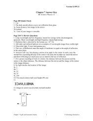
reversed. The right eye of the person is the left eye in the image. A common example<br />
of this is the word Ambulance printed in reverse on the front of the rescue vehicle.<br />
When drivers look in their rear view mirrors, they can read the word correctly. Table 7.1.3<br />
summarizes the characteristics that can be used to describe an image.<br />
Table 7.1.3 Words to Use to Describe an Image<br />
Image Characteristic Description<br />
Type real or virtual<br />
Attitude erect or inverted<br />
Magnification same size, smaller, larger<br />
Position distance from mirror surface<br />
1. You are a basketball player, 2 m tall. What is the shortest mirror you need to see your whole self in it?<br />
__________________________________________________________________________________________<br />
2. At night, have you ever seen your image in your living room window? Why don’t you see it during the<br />
daytime?<br />
__________________________________________________________________________________________<br />
3. (a) When you look into a mirror, where exactly is your image?<br />
__________________________________________________________________________________________<br />
(b) Is it on the mirror surface, in front of it, or behind it?<br />
__________________________________________________________________________________________<br />
(c) If you move closer to the mirror, what happens to your image?<br />
__________________________________________________________________________________________<br />
© Edvantage Interactive 2012 ISBN 978-0-9864778-3-6 Chapter 7 <strong>Light</strong> <strong>and</strong> <strong>Geometric</strong> <strong>Optics</strong> 205
Investigation 7-1A Looking into Mirrors<br />
Part 1<br />
Purpose<br />
To locate the image in a plane mirror<br />
Procedure<br />
1. Mount a sheet of clear glass or Plexiglas vertically, as in Figure 7.1.3. The Plexiglas will serve as a mirror. Place a<br />
c<strong>and</strong>le approximately 20 cm in front of the mirror. <strong>Light</strong> the c<strong>and</strong>le <strong>and</strong> turn off the room lights. You should see<br />
an image of the c<strong>and</strong>le in the mirror. Measure the distance from the c<strong>and</strong>le to the mirror. This is called the object<br />
distance.<br />
2. Obtain another unlit c<strong>and</strong>le the same height as the burning c<strong>and</strong>le. Place it behind the mirror, <strong>and</strong> move it<br />
around until it appears to be at the same location as the image of the c<strong>and</strong>le. Measure the distance from the<br />
image location to the mirror. This is called the image distance.<br />
3. Look very closely at the image in the mirror. Can you see a faint second image?<br />
Concluding Questions<br />
1. Where is the image in the mirror? How does the image distance compare with the object distance?<br />
2. According to your observations, where does the reflection of light occur in the “mirror”?<br />
Part 2<br />
Purpose<br />
To find out why the image in a plane mirror is “behind” the mirror<br />
Procedure<br />
1. Remove the light bulb section of your ray box. It will be your object for this investigation. Set up your light<br />
source approximately 10 cm in front of a plane mirror. A clothespin can be used to mount the mirror vertically.<br />
2. Use the five-slit opening of the plastic baffle for your ray box to create five beams of light from the bulb, as<br />
shown in Figure 7.1.6(a). Use a sharp pencil to make a few marks to indicate the path of one of the beams (a) as<br />
it travels to the mirror <strong>and</strong> (b) as it leaves the mirror. See Figure 7.1.6(b). Don’t move the mirror!<br />
3. Repeat step 2 for another beam of light going <strong>and</strong> coming from the mirror. Before you move the mirror, draw<br />
a line along the silvered back edge of the mirror where the reflection occurs. Also, mark the position of the<br />
filament of the light bulb as accurately as you can.<br />
Figure 7.1.6(a) Figure 7.1.6(b)<br />
206 Chapter 7 <strong>Light</strong> <strong>and</strong> <strong>Geometric</strong> <strong>Optics</strong> © Edvantage Interactive 2012 ISBN 978-0-9864778-3-6
4. Use your pencil marks as a guide to draw a line to show the path of the first beam of light (a) as it travelled to<br />
the mirror <strong>and</strong> (b) as it travelled away from the mirror after being reflected. Repeat for the second beam. When<br />
you draw a line to show the path that light takes, the line is properly called a light ray.<br />
5. Look carefully at one of the reflected rays. If you were looking directly into the mirror when the light bulb was in<br />
front of the mirror, from what point would this ray appear to have come?<br />
6. With your ruler, draw a dashed line “behind” the mirror for about 12 cm beyond the end of the reflected ray as<br />
in Figure 7.1.6(c). Repeat with the other reflected ray. Where do the two dashed lines meet? Mark this point with<br />
an X. Is this the same location as that of the image you saw in the mirror? To find out, put the light bulb <strong>and</strong><br />
the mirror back where they were before. Hold your pen where the X is as you look into the mirror. Is the image<br />
where the dashed lines meet?<br />
Figure 7.1.6(c)<br />
7. At the point where one of the beams reflects from the mirror, construct a line perpendicular to the mirror. This<br />
line is called a normal to the mirror. Measure the angle between the incoming or incident ray <strong>and</strong> the normal.<br />
This is called the incident angle. Also measure the angle between the normal <strong>and</strong> the reflected ray. This is the<br />
angle of reflection. Repeat this procedure for the other beam of light.<br />
Concluding Questions<br />
1. Compare the distance from the object to the mirror with the distance from the image to the mirror. Explain any<br />
difference you observe.<br />
2. The image in a plane mirror appears to be behind the mirror. Explain why this is so. Where does the light you see<br />
coming from the image really originate?<br />
3. For each beam, how did the angle of incidence compare with the angle of reflection? Is this consistent with<br />
what you observed with waves reflecting from a plane surface?<br />
Challenge<br />
1. Imagine that you wish to photograph your image in a plane wall mirror. You are st<strong>and</strong>ing 2 m in front of the<br />
mirror. At what distance should you set your camera lens? Try this at school or at home with your cellphone.<br />
© Edvantage Interactive 2012 ISBN 978-0-9864778-3-6 Chapter 7 <strong>Light</strong> <strong>and</strong> <strong>Geometric</strong> <strong>Optics</strong> 207
Investigation 7-1B Multiple Images<br />
Purpose<br />
To investigate multiple images in pairs of plane mirrors.<br />
Figure 7.1.7 illustrates two pieces of Plexiglas arranged to give many images of a single c<strong>and</strong>le. The Plexiglas acts as<br />
a mirror if the background is dark enough.<br />
Figure 7.1.7 Many images of a single object<br />
Procedure<br />
1. Arrange two flat mirrors at an angle of 120°, as shown in Figure 7.1.8. Place a small object such as a golf tee or<br />
a rubber stopper approximately 10 cm in front of the mirrors. Look into the mirrors <strong>and</strong> count the number of<br />
images you can see. How many images do you see when the mirrors are at 180°? Gradually decrease the angle<br />
between the mirrors <strong>and</strong> watch what happens to the number of images.<br />
Figure 7.1.8 Step 1<br />
208 Chapter 7 <strong>Light</strong> <strong>and</strong> <strong>Geometric</strong> <strong>Optics</strong> © Edvantage Interactive 2012 ISBN 978-0-9864778-3-6
2. To investigate the relationship between the number of images <strong>and</strong> the<br />
angle between the mirrors quantitatively, try setting your mirror at each<br />
of the angles in Table 7.1.4. In each trial, keep your head still (to avoid<br />
counting the same image twice by mistake) <strong>and</strong> count the number of<br />
images carefully. Copy the table into your notebook <strong>and</strong> record your<br />
results. Be sure to compare notes with other students.<br />
3. Look at the data. Can you figure out a simple rule that will allow you to<br />
predict how many images you will see if the mirrors are set at any one of<br />
these angles? Hint: There are 360° in a circle!<br />
4. If you think you have the rule figured out, predict how many images you<br />
will see if you set the mirrors at these angles: (a) 30° (b) 24° (c) 20° (d) 0°.<br />
(To check out your prediction for 0° , you will have to set the mirrors at 0°<br />
<strong>and</strong> then separate them, keeping them parallel with one another.)<br />
Concluding Questions<br />
1. What is the rule for predicting how many images you will see if you<br />
arrange two mirrors at an angle θ?<br />
2. You wish to make a kaleidoscope toy with which you will see the<br />
same pattern repeated four times including the object. At what angle<br />
should you arrange the two long plane mirrors inside the tube of the<br />
kaleidoscope?<br />
Table 7.1.4 Data Table<br />
Angle between<br />
Mirrors<br />
180°<br />
120°<br />
90°<br />
72°<br />
60°<br />
45°<br />
40°<br />
36°<br />
Number of<br />
Images<br />
Challenges<br />
1. Make an “infinity box.” Use one mirror tile as the floor of the box <strong>and</strong> make walls out of four other mirror tiles. At<br />
the centre of the “infinity box,” place an interesting object such as a flickering light bulb or a small moving toy.<br />
2. Make a periscope on a large scale, using mirror tiles, so you can see down a hallway over the heads of students<br />
in the hall.<br />
© Edvantage Interactive 2012 ISBN 978-0-9864778-3-6 Chapter 7 <strong>Light</strong> <strong>and</strong> <strong>Geometric</strong> <strong>Optics</strong> 209
7.1 Review Questions<br />
1. What is the relationship between frequency <strong>and</strong><br />
wavelength in the electromagnetic spectrum?<br />
2. What is considered the visible spectrum in the<br />
electromagnetic spectrum?<br />
3. Describe two forms of electromagnetic radiation<br />
that have wavelengths longer than visible light.<br />
4. List three forms of electromagnetic radiation that<br />
have frequencies shorter than visible light.<br />
5. Define the law of reflection <strong>and</strong> give one real-world<br />
example.<br />
6. In your own words, describe how you can use a<br />
mirror to see around a corner. In your explanation<br />
use the terms reflecting ray, incident ray, normal<br />
line, <strong>and</strong> law of reflection.<br />
7. What is the difference between image distance <strong>and</strong><br />
object distance.<br />
8. Why is the image you see in a plane mirror not<br />
considered a real image? (A real image is one<br />
formed by light arriving at a region in space, usually<br />
on a screen or film. The image in a plane mirror is<br />
called a virtual image.)<br />
210 Chapter 7 <strong>Light</strong> <strong>and</strong> <strong>Geometric</strong> <strong>Optics</strong> © Edvantage Interactive 2012 ISBN 978-0-9864778-3-6
9. How many images of yourself will you see if you look<br />
into a pair of hinged mirrors forming these angles?<br />
(Assume you can fit!)<br />
(a) 60° (d) 10°<br />
(b) 45° (e) 1°<br />
(c) 15°<br />
10. Imagine you are 180 cm tall. What is the shortest<br />
mirror you can use if you want to see your whole<br />
body? Use a diagram to illustrate your answer. Will it<br />
matter how far from the mirror you st<strong>and</strong>?<br />
<strong>11</strong>. Why is AMBULANCE written backwards on the front<br />
of the vehicle? Write your own name in such a way<br />
that it looks “right” when held up to a mirror. Draw a<br />
diagram to show why the letter “b” looks like a “d” in<br />
a mirror.<br />
12. In the Warm Up you made a pinhole camera. Draw<br />
a diagram that illustrates why the image on the wax<br />
paper or screen was inverted. What are the other<br />
characteristics of the image?<br />
13. Draw a diagram showing how you might use two<br />
prisms (45° –45° –90° ) as “mirrors” in a periscope.<br />
Show how the prisms must be arranged to act as<br />
mirrors.<br />
© Edvantage Interactive 2012 ISBN 978-0-9864778-3-6 Chapter 7 <strong>Light</strong> <strong>and</strong> <strong>Geometric</strong> <strong>Optics</strong> 2<strong>11</strong>
7.2 Curved Mirrors<br />
Warm Up<br />
Take a metal spoon. Hold it at arms length. Describe what the image looks like <strong>and</strong> how it changes as you bring it<br />
to your nose. Repeat with the other side. Share your findings with the class.<br />
_____________________________________________________________________________________________<br />
_____________________________________________________________________________________________<br />
_____________________________________________________________________________________________<br />
Types of Curved<br />
Mirrors<br />
You use many optical devices in your daily life, including eyeglasses, binoculars, cameras,<br />
microscopes, telescopes, <strong>and</strong> your own eyes. In this section, you will learn how some of<br />
these devices with mirrors work. Much use will be made of ray diagrams when explaining<br />
how light behaves when it passes through or into optical components such as plane <strong>and</strong><br />
curved mirrors. You will recall that a ray is simply a line drawn to show the path that light<br />
takes. Remember: A ray is a mathematical convenience <strong>and</strong> not a physical reality!<br />
The images you see in curved mirrors can be quite different from what you are<br />
accustomed to seeing in a plane mirror. If you st<strong>and</strong> close to a large concave mirror <strong>and</strong><br />
look into it, you will see yourself “right side up” <strong>and</strong> “larger than life.” A concave mirror has<br />
a shape that curves inward like a cave in a mountain. Some make-up or shaving mirrors<br />
are slightly concave. If you walk back from a concave mirror, you will find that at a certain<br />
distance your image is suddenly inverted <strong>and</strong> looks small (Figure 7.2.1(a)).<br />
Convex mirrors always make you look smaller than real life, no matter what distance<br />
you are from them (Figure 7.2.1(b)). Convex mirrors curve outwards in the opposite<br />
direction of concave mirrors. You see convex mirrors in shops, where they are strategically<br />
placed so that the shop owner can obtain a wide-angle view of the store <strong>and</strong> the<br />
customers in it. Some rear view mirrors may have a small convex section on them so that<br />
the driver gets a wider angle of view of what is behind him.<br />
(a)<br />
Figure 7.2.1 (a) A concave mirror; (b) A convex mirror<br />
212 Chapter 7 <strong>Light</strong> <strong>and</strong> <strong>Geometric</strong> <strong>Optics</strong> © Edvantage Interactive 2012 ISBN 978-0-9864778-3-6<br />
(b)
Characteristics<br />
of a Concave or<br />
Converging Mirror<br />
PA = principal axis<br />
V = vertex<br />
F = focal point<br />
f = focal length<br />
C = centre of curvature<br />
r = radius of curvature<br />
Figure 7.2.2 Characteristics of a concave or converging mirror<br />
��<br />
A good quality concave mirror is shaped so that rays of light incident on the mirror’s<br />
surface will reflect predictably. Figure 7.2.2 describes the characteristics of a converging<br />
mirror. The principal axis (PA) is an imaginary line drawn through the vertex (V),<br />
perpendicular to surface of the curved mirror. Rays parallel to the principal axis will<br />
reflect through a single point, called the focal point (F). The distance between the vertex<br />
<strong>and</strong> the focal point is called the focal length (f). The point where parallel rays of light<br />
converge in front of a concave mirror is also called the principal focus, if the focussing<br />
occurs on the principal axis of the mirror.<br />
��<br />
�<br />
� �<br />
Reflection is reversible so light coming from the focal point will reflect parallel to<br />
the principal axis. Of course, any ray incident on the mirror will reflect in such a way that<br />
the angle of incidence equals the angle of reflection. This is illustrated in Figure 7.2.3 as<br />
ray 1 <strong>and</strong> ray 2. Ray 3 shows that any ray travelling through the focal point to the vertex<br />
will be reflected directly back along the same path.<br />
The point C is called the centre of curvature. This is a point that represents the<br />
centre of the sphere from which the curved mirror was cut. The radius of curvature (r) is<br />
the distance from the centre of curvature to the mirror surface.<br />
�����<br />
�����<br />
�����<br />
Figure 7.2.3 <strong>Light</strong> rays reflecting on a concave mirror<br />
© Edvantage Interactive 2012 ISBN 978-0-9864778-3-6 Chapter 7 <strong>Light</strong> <strong>and</strong> <strong>Geometric</strong> <strong>Optics</strong> 213<br />
�<br />
�<br />
Diagrams used to illustrate concave mirrors are circular <strong>and</strong> two-dimensional. An<br />
inexpensive concave mirror is spherical in three dimensions. A top quality concave mirror<br />
is not quite spherical; the ideal mirror will be discussed later.<br />
�
Predicting Where an<br />
Image Will Form<br />
You can predict where a concave mirror will form an image if you simply keep in mind<br />
what the mirror was shaped to do <strong>and</strong> the behaviour of the two rays in Figure 7.2.3.<br />
In Figure 7.2.4, two rays have been drawn coming from the top of the object<br />
(a c<strong>and</strong>le). Ray 1 is parallel to the principal axis. It reflects from the mirror <strong>and</strong> passes<br />
through the focal point F. Ray 2 passes through the focal point, reflects off the mirror, <strong>and</strong><br />
moves out parallel to the principal axis. An image of the top of the c<strong>and</strong>le flame forms<br />
where these two rays converge.<br />
������<br />
���������<br />
���� �<br />
�����<br />
Figure 7.2.4 The two rays from the top of the c<strong>and</strong>le form an image after reflecting off the mirror.<br />
In Figure 7.2.5, a similar pair of rays has been drawn coming from a point at the<br />
bottom of the c<strong>and</strong>le. These rays reflect <strong>and</strong> converge at a point in front of the mirror. The<br />
image of the bottom of the c<strong>and</strong>le forms on a line just above the image of the top of the<br />
flame. Any number of pairs of rays might be drawn from points elsewhere on the c<strong>and</strong>le.<br />
All of these pairs of rays will converge on a line the same distance from the mirror as the<br />
other image points.<br />
������<br />
���������<br />
���� �<br />
�����<br />
Figure 7.2.5 With the addition of two rays from the bottom of the c<strong>and</strong>le, a complete image forms.<br />
The object is located quite far from the mirror. It is at a distance greater than the<br />
focal length <strong>and</strong> also greater than the radius of curvature of the mirror. To summarize, the<br />
characteristics of the image are:<br />
• Type: real<br />
• Attitude: inverted<br />
• Magnification: smaller than the object<br />
• Position: closer to the mirror<br />
214 Chapter 7 <strong>Light</strong> <strong>and</strong> <strong>Geometric</strong> <strong>Optics</strong> © Edvantage Interactive 2012 ISBN 978-0-9864778-3-6<br />
�<br />
�
Quick Check<br />
1. Complete these ray diagrams to show where the image of the object will form <strong>and</strong> what its relative size will<br />
be. Draw at least two rays for each diagram.<br />
(a)<br />
���<br />
(b)<br />
���<br />
(c)<br />
���<br />
The Concave Mirror<br />
as a Magni�er<br />
� �<br />
�<br />
�<br />
� �<br />
Type:<br />
Attitude:<br />
Magnification:<br />
Position:<br />
Type:<br />
Attitude:<br />
Magnification:<br />
Position:<br />
Type:<br />
Attitude:<br />
Magnification:<br />
Position:<br />
If you place your face very close to a concave mirror, so that you are closer than the<br />
principal focus, shown in Figure 7.2.6, you see an enlarged virtual image in the mirror.<br />
Unlike a real image from a concave mirror, the virtual image is right side up. The location<br />
of the image can be predicted using a ray diagram.<br />
A ray coming from the top of the object in a direction parallel to the principal axis<br />
will reflect through the principal focus, as usual. To locate the image, a second ray is<br />
drawn in a direction such that it appears to have come from the principal focus. This ray<br />
will reflect out parallel to the principal axis. The reflected rays do not converge anywhere.<br />
In fact, they diverge <strong>and</strong> cannot possibly form part of a real image.<br />
������<br />
�<br />
�������������<br />
Figure 7.2.6 When the object is between the principal focus<br />
<strong>and</strong> the mirror, the virtual image is larger than the object.<br />
© Edvantage Interactive 2012 ISBN 978-0-9864778-3-6 Chapter 7 <strong>Light</strong> <strong>and</strong> <strong>Geometric</strong> <strong>Optics</strong> 215
The Mirror Equation<br />
Now, imagine you are looking into the mirror. From what point would the two<br />
reflected rays appear to come? If you extrapolate the two rays back behind the mirror,<br />
they appear to be coming from a point at the top of the virtual image in Figure 7.2.6.<br />
Similar pairs of rays might be drawn from other points on the object. Coinciding image<br />
points would then be found on the line representing the virtual image in the figure. This<br />
image is virtual, erect, <strong>and</strong> enlarged.<br />
Can the location of an image formed by a concave mirror be predicted by calculation?<br />
There is an equation for concave mirrors that permits you to do this quite easily. To show<br />
where the equation comes from, some simple geometry will be used. In Figure 7.2.7, a<br />
third ray has been drawn from the object to the mirror. This ray passes along a radius of<br />
the mirror. It therefore strikes the mirror perpendicularly <strong>and</strong> reflects right back on itself.<br />
�<br />
� �<br />
� � � �<br />
Figure 7.2.7 Earlier diagrams only used two rays. In this diagram a third ray has been added.<br />
216 Chapter 7 <strong>Light</strong> <strong>and</strong> <strong>Geometric</strong> <strong>Optics</strong> © Edvantage Interactive 2012 ISBN 978-0-9864778-3-6<br />
�<br />
Several triangles are created in Figure 7.2.7. Notice that ∆IBF <strong>and</strong> ∆O'DF are similar.<br />
The height of the object is OA, which equals O'D. Distance FD is approximately equal to<br />
the focal length f of the mirror. The diagram exaggerates the difference between FE (f )<br />
<strong>and</strong> FD. You may assume that FD is very, very close to being equal to the focal length, f.<br />
Since ∆IBF is similar to ∆O'DF, ∴<br />
IB<br />
O'D<br />
= BF<br />
FD<br />
Now O'D is the same as OA (the height of the object) <strong>and</strong> FD is almost equal to f, so<br />
IB<br />
OA<br />
= BF<br />
f<br />
Notice that ∆OAF is similar to ∆ I'EF, so that<br />
I'E<br />
OA<br />
= EF<br />
AF<br />
Now I'E is the same as IB (height of the image) <strong>and</strong> EF is almost equal to f , so<br />
Combining equations (1) <strong>and</strong> (2),<br />
IB<br />
OA<br />
BF<br />
f<br />
=<br />
=<br />
f<br />
AF<br />
f<br />
AF<br />
(1)<br />
(2)<br />
(3)<br />
��<br />
��<br />
�
Now image distance di = BF + f, <strong>and</strong> object distance do = AF + f, so we can rewrite<br />
equation (3) like this:<br />
di – f<br />
f<br />
=<br />
f<br />
do – f<br />
Therefore, (d i – f )(d o – f ) = f 2 , or<br />
Dividing through by f d i d o gives 1<br />
f<br />
This can be re-arranged to read<br />
d i d o – f d o – f d i + f 2 = f 2 , or<br />
d i d o – f d o – f d i = 0<br />
© Edvantage Interactive 2012 ISBN 978-0-9864778-3-6 Chapter 7 <strong>Light</strong> <strong>and</strong> <strong>Geometric</strong> <strong>Optics</strong> 217<br />
– 1<br />
d i<br />
– 1<br />
d o<br />
1<br />
+<br />
do 1<br />
=<br />
di 1<br />
f<br />
= 0<br />
This equation will be referred to as the mirror equation.<br />
Sample Problem 7.2.1 — Using the Mirror Equation<br />
A concave mirror has a focal length of 20.0 cm. If an object is 1.00 m in front of the mirror, where will the image<br />
form?<br />
What to Think About<br />
1. Determine what is required.<br />
2. Select <strong>and</strong> rearrange formula.<br />
3. Solve for image location.<br />
How to Do It<br />
Find image distance.<br />
1 +<br />
do 1 di = 1 so<br />
f<br />
1<br />
di 1<br />
di =<br />
= 1<br />
f –<br />
=<br />
1<br />
d o<br />
1<br />
20.0 cm –<br />
4<br />
100.0 cm<br />
d i = 25.0 cm<br />
1<br />
100.0 cm<br />
The image forms 25.0 cm in front of the mirror.
Practice Problems 7.2.1 — Using the Mirror Equation<br />
1. A real image forms 25.0 cm in front of a concave mirror, which has a focal length of 20.0 cm. How far is the<br />
object from the mirror?<br />
2. An image forms in front of a concave mirror at the same distance from the mirror as the object. Solve for the<br />
object or the image distance in terms of the focal length, f.<br />
3. What is the focal length of a concave mirror that forms an image on a screen 40.0 cm away when an object is<br />
20.0 cm in front of the mirror?<br />
4. An object is placed 10.0 cm in front of a concave mirror of focal length 15.0 cm. Solve for d i . Why is the answer<br />
negative?<br />
The Ideal Shape for a<br />
Concave Mirror<br />
The concave mirrors you have used so far have been either cylindrical (with the ray box)<br />
or spherical. These mirrors are relatively inexpensive to manufacture <strong>and</strong> are adequate for<br />
many uses. You probably noticed that they do not focus light precisely.<br />
Parallel rays entering the mirror are converged to a narrow region, but not<br />
precisely to a point. There is some aberration. For precision work, as in quality telescopes,<br />
aberration must be avoided. The mirror must be shaped perfectly. What is the perfect<br />
shape for a concave mirror? In two dimensions, the name of the perfect curve for a<br />
concave mirror is a parabola. The three-dimensional equivalent of a parabola is called a<br />
paraboloid. To visualize what a parabola looks like, imagine a baseball being tossed into<br />
the air by a fielder to a catcher.<br />
218 Chapter 7 <strong>Light</strong> <strong>and</strong> <strong>Geometric</strong> <strong>Optics</strong> © Edvantage Interactive 2012 ISBN 978-0-9864778-3-6
Convex or Diverging<br />
Mirrors<br />
�����<br />
�����<br />
�����<br />
The path the ball takes is parabolic. Figure 7.2.8 shows what a parabola looks like.<br />
Reflecting telescopes use parabolic mirrors. Radio telescopes are also parabolic in shape,<br />
but they are much larger than optical telescopes.<br />
Figure 7.2.8 The shape of a parabola<br />
A convex mirror produces a virtual image that is erect <strong>and</strong> smaller than the object.<br />
Figure 7.2.9 illustrates the reflection of rays off a convex mirror. Note that the rays<br />
appear to be converging at the mirror’s focal point.<br />
Figure 7.2.9 Rays reflecting off a convex mirror<br />
© Edvantage Interactive 2012 ISBN 978-0-9864778-3-6 Chapter 7 <strong>Light</strong> <strong>and</strong> <strong>Geometric</strong> <strong>Optics</strong> 219<br />
�<br />
Figure 7.2.10 shows how to find the virtual image in a diverging mirror. Ray 1 is<br />
parallel to the principal axis <strong>and</strong> the reflected ray appears to have come from the focal<br />
point. Ray 2 comes from a point on the object <strong>and</strong> travels toward the focal point. The<br />
reflected ray is parallel to the principal axis. The image forms where the rays appear to<br />
intersect.<br />
Figure 7.2.10 A virtual image in a convex mirror<br />
�
Investigation 7-2A An Introduction to Curved Mirrors<br />
Purpose<br />
To observe how light reflects from concave <strong>and</strong> convex mirrors<br />
Part 1: Convex Mirrors<br />
Procedure<br />
1. Set up a ray box with a five-slit baffle. Adjust the position of the lens of the ray box so that all five beams are<br />
parallel. Aim the parallel beams at a cylindrical convex mirror, as shown in Figure 7.2.<strong>11</strong>.<br />
Figure 7.2.<strong>11</strong> Step 1— Convex mirror<br />
������������<br />
�������������<br />
2. Carefully mark the position of one of the incident beams <strong>and</strong> the reflected beam corresponding to it. Trace<br />
the outline of the reflecting surface of the mirror. Remove the mirror. Draw a normal to the mirror at the point<br />
of reflection. Measure the angle of incidence <strong>and</strong> the angle of reflection. Does the reflection resemble what<br />
happened at a point on a plane mirror?<br />
3. Obtain a spherical convex mirror from your teacher. Its shape is like a section of a sphere. Look into the mirror<br />
<strong>and</strong> describe the image you see. Is it right side up or inverted? Is it larger than your face, smaller, or the same<br />
size?<br />
Concluding Questions<br />
1. Why is a convex mirror called a diverging mirror?<br />
2. Why does a convex mirror give a wide-angle view when you look at it?<br />
3. Describe the nature of the image you see in a diverging mirror. Is it real or virtual? Enlarged or smaller? Erect or<br />
inverted?<br />
4. What would you look like in a tall, vertical mirror shaped like a cylinder?<br />
Part 2 Concave Mirrors<br />
Procedure<br />
1. Aim the five parallel beams from your ray box at a cylindrical concave mirror, as shown in Figure 7.2.12. Sketch<br />
the incident <strong>and</strong> reflected beams.<br />
Figure 7.2.12 Step 1 — Concave mirror<br />
������������<br />
��������������<br />
220 Chapter 7 <strong>Light</strong> <strong>and</strong> <strong>Geometric</strong> <strong>Optics</strong> © Edvantage Interactive 2012 ISBN 978-0-9864778-3-6
2. Block the light from the outermost beams coming from the ray box, so that only the middle part of the<br />
cylindrical mirror is being used. Do you notice an improvement in the focussing? (Is the focussed light<br />
concentrated in a smaller area than before?) Sketch the incident <strong>and</strong> reflected beams again.<br />
3. Measure the distance from the vertex or geometric centre of the concave mirror to the point where the light<br />
comes together on the axis of the mirror. This distance is called the focal length (f) of the mirror.<br />
Concluding Questions<br />
1. Why is a concave mirror called a converging mirror?<br />
2. Why are concave mirrors used in some telescopes?<br />
3. Does a cylindrical mirror focus all the incoming parallel beams of light to a single point? Discuss.<br />
Part 3: Finding the Focal Length of a Spherical Concave Mirror<br />
Procedure<br />
1. Set up your spherical concave mirror on an optical bench so that it faces a small light source, such as the<br />
bulb from an opened ray box or a c<strong>and</strong>le flame, which is at least 5 m away. See Figure 7.2.13. The rays of light<br />
coming from a small, distant source will be very close to being parallel. Wherever they converge in front of the<br />
mirror will be very, very close to being the focal point. If the focal point is on the principal axis of the mirror, it<br />
will be the principal focus. The distance from the vertex of the mirror to the principal focus is the focal length of<br />
your mirror.<br />
���������������������������������<br />
���������������������������<br />
Figure 7.2.13 Step 1 — Finding the focal length<br />
������<br />
����������� �<br />
�������������������������<br />
2. To see where the light from the distant source focuses, you will need a screen. Since you do not want to block<br />
the light coming into the mirror completely, cut a strip of file card about 1 cm wide <strong>and</strong> mount it in a screen<br />
holder in front of the concave mirror. Move the screen back <strong>and</strong> forth in front of the mirror until you see a<br />
sharply focussed, very small image of the distant light source. If the light source is sufficiently far away <strong>and</strong><br />
small, the image you see will be, for practical purposes, a point. The distance from the vertex of the mirror to<br />
this point is the focal length of your mirror.<br />
3. For future investigations, you will need to know the focal length of a spherical concave mirror. It is important to<br />
measure the focal length of your mirror carefully <strong>and</strong> label the mirror so that you use the same one later. Record<br />
the focal length on a small piece of masking tape on the side of the mirror.<br />
Concluding Questions<br />
1. If you placed the light source closer to the mirror (say 1.5 m), would the light from the source come to a focus?<br />
Would it converge at the principal focus? Discuss.<br />
2. Why is it important to use a distant light source when you are trying to measure the focal length of a concave<br />
mirror?<br />
© Edvantage Interactive 2012 ISBN 978-0-9864778-3-6 Chapter 7 <strong>Light</strong> <strong>and</strong> <strong>Geometric</strong> <strong>Optics</strong> 221
Investigation 7-2B Locating Images in Concave Mirrors<br />
Purpose<br />
To locate images formed by a concave mirror<br />
Procedure<br />
1. Mount your concave mirror at the far end of your optical bench or metre stick. Measure off a distance equal to<br />
the focal length of your mirror <strong>and</strong> mark the position of the principal focus on your metre stick with an F written<br />
on masking tape. At a distance equal to two focal lengths (2f), write a letter C on the tape.<br />
2. Place a suitable object, such as a small c<strong>and</strong>le or a miniature light bulb, at the other end of the metre stick or<br />
optical bench. The object distance d o will be greater than 2f. Locate the image by moving a thin white card back<br />
<strong>and</strong> forth in front of the mirror until you see the image of the object in sharp focus. Measure the distance from<br />
the vertex of the mirror to (a) the object (d o ) <strong>and</strong> (b) the image (d i ). Record these distances.<br />
������<br />
�����������<br />
��<br />
� �<br />
Figure 7.2.14 Step 1 — Locating an image in a concave mirror<br />
�<br />
��������<br />
������<br />
3. Try a second object position at a distance greater than 2f. Locate the image <strong>and</strong> object <strong>and</strong> measure d o <strong>and</strong> d i .<br />
4. Place the object at a distance of 2f from the mirror. Locate the image <strong>and</strong> measure d o <strong>and</strong> d i .<br />
5. Place the object at a distance of approximately 1.5f from the mirror. Locate the image <strong>and</strong> measure d o <strong>and</strong> d i .<br />
6. Place the object at the focal point F. Can you use this set-up to make a spotlight? If so, how would you do it?<br />
7. Place the object at a distance less than f from the mirror. Can you form a real image? Look directly into the<br />
mirror. Can you see a virtual image? Describe the image.<br />
Concluding Questions<br />
1. Draw ray diagrams showing where <strong>and</strong> why the real images formed when the object was at these distances:<br />
(a) >2f, (b) 2f, (c) 1.5f, (d) f.<br />
2. If this concave mirror is being used as an astronomical telescope, where will the image form?<br />
3. If the mirror is being used in an automobile headlight or in a spotlight, where will you place the object?<br />
4. Why is it difficult to obtain a good image of the object when it is at F?<br />
5. In general, what object distance range will give a real image?<br />
6. In general, what object distance range will give a virtual image?<br />
222 Chapter 7 <strong>Light</strong> <strong>and</strong> <strong>Geometric</strong> <strong>Optics</strong> © Edvantage Interactive 2012 ISBN 978-0-9864778-3-6
7.2 Review Questions<br />
1. What is the difference between a convex <strong>and</strong> concave lens?<br />
2. What is the difference between a diverging <strong>and</strong> converging lens?<br />
3. Which type of mirror makes the image smaller than real life?<br />
4. Which type of mirror would you use for the following situations? Explain your answer.<br />
(a) make-up or shaving<br />
(b) security mirror in a store<br />
(c) clothes store<br />
5. Match the following terms with the correct definition<br />
___ Principal axis A. The geometric centre of the curved mirror<br />
___ Vertex B. The point that represents the centre of the sphere from which the mirror was<br />
cut<br />
___ Focal point C. The distance between the focal point <strong>and</strong> the vertex<br />
___ Centre of curvature D. The distance between the centre of curvature <strong>and</strong> the mirror<br />
___ Radius of curvature E. An imaginary line drawn from the vertex <strong>and</strong> perpendicular to the curved<br />
mirror at that point<br />
___ Focal length F. Where light rays parallel to the principal axis converge after being reflected<br />
6. For converging mirrors, describe the image characteristics for the following object positions.<br />
Far away<br />
Outside centre of curvature<br />
At the centre of curvature<br />
Object Position Image Characteristics<br />
Between the focal point <strong>and</strong> centre of curvature<br />
At the focal point<br />
Between focal point <strong>and</strong> vertex<br />
© Edvantage Interactive 2012 ISBN 978-0-9864778-3-6 Chapter 7 <strong>Light</strong> <strong>and</strong> <strong>Geometric</strong> <strong>Optics</strong> 223
7. What shape of “trick” mirror would make:<br />
(a) A thin person look larger? ___________________________<br />
(b) A large person look thinner? _________________________<br />
(c) A tall person look shorter? ___________________________<br />
(d) A short person look taller? ___________________________<br />
8. Draw the ray diagrams for the following concave mirrors:<br />
(a) Object is more than two focal lengths away from the mirror<br />
(b) Object is between one <strong>and</strong> two focal lengths.<br />
(c) Object is at focal point.<br />
(d) Object is between mirror <strong>and</strong> focal point.<br />
9. On the diagram below, use two rays to show where the image of the arrow will be.<br />
������<br />
�������������<br />
� �<br />
�������������<br />
����������<br />
���������<br />
224 Chapter 7 <strong>Light</strong> <strong>and</strong> <strong>Geometric</strong> <strong>Optics</strong> © Edvantage Interactive 2012 ISBN 978-0-9864778-3-6
10. (a) Can a convex mirror form a real image? Explain your answer with a ray diagram.<br />
(b) Can a convex mirror form an enlarged image? Explain your answer with a ray diagram.<br />
Challenge<br />
1. The commercially available double concave mirror shown<br />
here is called a Mirage. It creates a very realistic image at the<br />
opening of the top mirror. Is this image real or is it virtual? On<br />
a separate sheet of paper, draw a ray diagram to explain why<br />
the image forms where it does.<br />
© Edvantage Interactive 2012 ISBN 978-0-9864778-3-6 Chapter 7 <strong>Light</strong> <strong>and</strong> <strong>Geometric</strong> <strong>Optics</strong> 225
7.3 Refraction of <strong>Light</strong><br />
Warm Up<br />
Fill a beaker about three-quarters full of water. Place a pencil or pen in the beaker. Draw what you observe.<br />
Explain your diagram by adding notes to it.<br />
Refraction<br />
Figure 7.3.2 Lines of soldiers<br />
bend as they move from<br />
one medium (pavement) to<br />
another (mud).<br />
A h<strong>and</strong> magnifier lens can make the Sun’s rays converge to a small area on a piece of<br />
paper (Figure 7.3.1). It is possible to ignite paper this way. Why does the light converge or<br />
come together? The property of light involved here is called refraction. Refraction occurs<br />
when light travels from one medium such as air into another medium such as glass. The<br />
change in direction of the light at the boundary of the two media is called refraction. The<br />
bend is due to the change in the speed of light. <strong>Light</strong> travels slower through different<br />
materials or media. (“Media” is the plural of “medium.”) The slower the light entering a<br />
medium, the greater the bend the light will make.<br />
226 Chapter 7 <strong>Light</strong> <strong>and</strong> <strong>Geometric</strong> <strong>Optics</strong> © Edvantage Interactive 2012 ISBN 978-0-9864778-3-6<br />
�����<br />
Figure 7.3.1 <strong>Light</strong> refracted through a h<strong>and</strong> lens converges on a point that becomes so hot, it sets the<br />
paper on fire.<br />
To underst<strong>and</strong> what causes refraction, imagine rows of soldiers marching side by<br />
side down a paved road. This is the first medium. There are many rows of soldiers one<br />
behind the other. Think of the first row of soldiers as a wavefront. The soldiers one behind<br />
the other form lines (Figure 7.3.2). The soldiers veer off the road at an angle toward a<br />
muddy field. This is the second medium. As soon as the first soldiers in the wavefront,<br />
reach the muddy field, each soldier in turn is slowed down, but tries to remain in step<br />
with adjacent soldiers. The wavefront is therefore refracted as it enters the slower<br />
medium. When the wavefront leaves the muddy field, the process is reversed, <strong>and</strong> the<br />
wavefront returns to its original direction.
Refractive Index<br />
Table 7.3.1 Indices of Refraction<br />
Medium<br />
Index of<br />
Refraction<br />
Water at 20°C 1.333<br />
Diamond 2.42<br />
1.5–1.9<br />
Glass<br />
(depends on<br />
composition)<br />
Air 1.00029<br />
Quartz crystal 1.54<br />
Snell’s Law of<br />
Refraction<br />
As the light enters a medium like glass it will bend. How much light bends depends on<br />
the refractive index of the medium in which the light travels. The refractive index of a<br />
medium is given the symbol n. It is calculated by dividing the speed of light in a vacuum<br />
by the speed of light in a medium:<br />
speed of light in a vacuum<br />
n =<br />
speed of light in a medium<br />
© Edvantage Interactive 2012 ISBN 978-0-9864778-3-6 Chapter 7 <strong>Light</strong> <strong>and</strong> <strong>Geometric</strong> <strong>Optics</strong> 227<br />
= c<br />
v<br />
Table 7.3.1 lists some indices of refraction. For water, the index of refraction<br />
is 1.33, or approximately 4/3. For glass, the index of refraction is approximately<br />
3/2. Different kinds of glass have slightly different indices of refraction. The index<br />
of refraction depends on the colour wavelength of light used <strong>and</strong> on the purity,<br />
temperature <strong>and</strong> composition of the material into which the light is travelling.<br />
Notice that the index of refraction of air is very close to 1. In other words,<br />
there is very little refraction when light travels from a vacuum (as in space) into air.<br />
Also, this means that the indices of refraction for light travelling from air into other<br />
media will be essentially the same as for light travelling from a vacuum into the<br />
same media.<br />
Generally, when light passes from a medium of low refractive index to one<br />
of higher refractive index, the light bends toward the normal. When light passes<br />
from a medium of higher refractive index to one of lower refractive index, the light<br />
bends away from the normal.<br />
Figure 7.3.3 shows a ray of light travelling from a vacuum into a medium such as glass.<br />
The ray refracts toward the normal. The incident ray is labelled AO <strong>and</strong> the refracted ray<br />
is OC. In the diagram, AO <strong>and</strong> OC are radii of the same circle; therefore they are equal in<br />
length. AB is the distance of the incident ray from the normal, <strong>and</strong> CD is the distance of<br />
the refracted ray from the normal. The angle of incidence is θ i ; the angle of refraction is θ r .<br />
�<br />
�<br />
�<br />
�<br />
������<br />
�<br />
�<br />
������<br />
�<br />
Figure 7.3.3 A ray of light refracts as it moves from a vacuum to a medium (glass).<br />
The two triangles ABO <strong>and</strong> CDO are right-angled triangles. In these two triangles,<br />
trigonometry tells us that<br />
sin θi = AB<br />
OA <strong>and</strong> sin θ CD<br />
r = =<br />
OC CD<br />
OA<br />
Dutch mathematician Willebrord Snell (1591–1626) discovered that there was<br />
an exact relationship between the angle of incidence <strong>and</strong> the angle of refraction for<br />
light travelling from one medium into another. Recall that for small angles, the angle of<br />
incidence was equal to the angle of refraction or vice versa. Snell was able to show that<br />
there was a relationship that was true for all angles greater than 0°.
In Figure 7.3.3,<br />
AB<br />
OA<br />
CD<br />
OC<br />
= sin θ i<br />
sin θ r<br />
= n where n is a constant for a given medium.<br />
It is called the index of refraction of the medium into which the light is moving from<br />
a vacuum.<br />
Snell’s law looks like this for light going from a vacuum into any medium:<br />
sin θi = n<br />
sin θr where n is the index of refraction of the medium into which the light is moving. The<br />
general form of Snell’s law accounts for two media where n1 is the incident medium <strong>and</strong><br />
n2 is the refracting medium.<br />
sin θi =<br />
sin θr n2 n1 n 1 sin θ i = n 2 sin θ r<br />
Quick Check<br />
1. <strong>Light</strong> entering a block of glass at an angle of incidence of 18.5° leaves the boundary between the air <strong>and</strong> the<br />
glass at an angle of 12.0°. What is the index of refraction of this type of glass?<br />
2. <strong>Light</strong> is incident on a diamond at an angle of 10.0°. At what angle will it refract?<br />
3. A beam of light is incident on a sheet of glass in a window at an angle of 30°. Describe exactly what path the<br />
light beam will take<br />
(a) as it enters the glass.<br />
(b) as it leaves the other side of the glass. Assume n = 1.500.<br />
4. What optical device is designed specifically to separate the colours in “white light” using the fact that<br />
different wavelengths (colours) have different indices of refraction in glass? Which colour refracts most?<br />
228 Chapter 7 <strong>Light</strong> <strong>and</strong> <strong>Geometric</strong> <strong>Optics</strong> © Edvantage Interactive 2012 ISBN 978-0-9864778-3-6
Using Snell’s Law to<br />
Calculate the Critical<br />
Angle<br />
You can increase the angle of incidence of the light going from water into air until<br />
you can no longer observe refraction. The smallest angle at which you can observe no<br />
refraction <strong>and</strong> only reflection is called the critical angle (θic ). At angles equal to or greater<br />
than the critical angle, the water-air boundary acts as a perfect mirror. At any angle equal<br />
to or greater than the critical angle, all light coming from the water will reflect back into<br />
the water. This is called total internal reflection. At incident angles less than the critical<br />
angle, refraction <strong>and</strong> weak reflection can both be observed.<br />
In Figure 7.3.4, if a ray of light is coming from air into water, Snell’s law might be<br />
applied:<br />
sin θi = nw where nw is the index of refraction of water.<br />
sin θr ������������<br />
���<br />
���<br />
�����<br />
��������������<br />
�����������������<br />
������������<br />
��������������<br />
�������������<br />
© Edvantage Interactive 2012 ISBN 978-0-9864778-3-6 Chapter 7 <strong>Light</strong> <strong>and</strong> <strong>Geometric</strong> <strong>Optics</strong> 229<br />
���<br />
���<br />
�����<br />
��������������<br />
���������������������������<br />
Figure 7.3.4 (a) The incident ray reaches the water’s surface at less than θic so it passes into the air; (b) The<br />
incident ray reaches the water’s surface at the θic so it is reflected back.<br />
For angles less than the critical angle, the path of light is reversible. For a ray of light<br />
coming from water out into air, what was the incident angle now becomes the angle of<br />
refraction <strong>and</strong> vice versa. For light going from water out into air:<br />
sin θi =<br />
sin θr 1<br />
nw Consider what happens as the incident angle approaches the critical angle,<br />
θic (Figure 7.3.4). The angle of refraction approaches 90°. Just as the critical angle is<br />
approached, we can write:<br />
sin θ ic<br />
sin 90°<br />
= 1<br />
n w<br />
where n w is the index of refraction for light coming from air into water.<br />
Solving for the critical angle, sin 90° = 1.0000 so:<br />
sinθ ic = (1)(1.000)<br />
n w<br />
= 1.000<br />
1.33<br />
<strong>and</strong> θ ic = 48.6°<br />
The critical angle for water is therefore 48.6°.<br />
= 0.750
Quick Check<br />
1. Calculate the critical angle for diamond, which has an index of refraction of 2.42.<br />
2. What is the critical angle for a glass that has an index of refraction of 1.500?<br />
3. A certain material has a critical angle of 52.0°. What is its index of refraction?<br />
The Rainbow —<br />
Dispersion by<br />
Raindrops<br />
If you have ever looked at a rainbow carefully, you probably have noticed these<br />
conditions prevailed:<br />
• The Sun was behind you.<br />
• There were rain clouds in the sky in front of you.<br />
• The rainbow forms an arc of a circle.<br />
• In the primary bow (the brightest one), red is at the top <strong>and</strong> violet at the bottom.<br />
• In the secondary bow, if it is visible, the colours are in reverse order.<br />
Figure 7.3.5(a) illustrates what happens inside the raindrops. White light from the<br />
Sun refracts as it enters a drop. The white light is dispersed into component colours<br />
during the refraction. All colours of light experience internal reflection at the back of the<br />
drop. They are then refracted again <strong>and</strong> further dispersed as they leave the drop at the<br />
“front.”<br />
When you see a rainbow, you see the dispersive effects of millions of drops of water,<br />
not just one or two! You see red at the top of the primary bow with all the other rainbow<br />
colours below, ending in violet.<br />
��������<br />
������<br />
����������������������<br />
����������������������<br />
���<br />
���<br />
������ ������<br />
Figure 7.3.5 (a) A primary rainbow: The red part of the rainbow is<br />
42° from the “axis” of the bow; violet is 40° from the “axis.”<br />
230 Chapter 7 <strong>Light</strong> <strong>and</strong> <strong>Geometric</strong> <strong>Optics</strong> © Edvantage Interactive 2012 ISBN 978-0-9864778-3-6<br />
���
Wave Speed <strong>and</strong><br />
Index of Refraction<br />
(Enrichment)<br />
Sometimes a secondary, fainter rainbow may be seen above the primary rainbow.<br />
A secondary rainbow has the colours in reverse order. Figure 7.3.5(b) shows the double<br />
internal reflection that happens inside droplets producing a secondary rainbow.<br />
��������<br />
���������<br />
�������������<br />
© Edvantage Interactive 2012 ISBN 978-0-9864778-3-6 Chapter 7 <strong>Light</strong> <strong>and</strong> <strong>Geometric</strong> <strong>Optics</strong> 231<br />
���<br />
������<br />
������<br />
Figure 7.3.5 (b) A secondary rainbow: The reversed colours of the secondary (higher) rainbow are due to<br />
double reflection of the Sun’s light within the droplets.<br />
Proof That the Index of Refraction n = v 1<br />
v 2<br />
Consider a wavefront (labelled Aa in Figure 7.3.6) arriving at the boundary between two<br />
media. Medium 2 is one in which light slows down from speed v 1 to speed v 2 . In the time<br />
t it takes for the wavefront at end A to reach the boundary B, the wavefront in medium 1<br />
travels a distance AB, which equals v 1 t.<br />
In the same time t, end a of the wavefront travels a distance ab inside medium 2.<br />
The distance ab equals v 2 t.<br />
In Figure 7.3.6, you will notice that sin θ i = AB/aB <strong>and</strong> sin θ r = ab/aB. Therefore the<br />
index of refraction, n, is equal to<br />
n = sin θ i<br />
sin θ r<br />
= AB/aB<br />
ab/aB<br />
= AB<br />
ab = v 1 t<br />
v 2 t = v 1<br />
v 2<br />
Therefore, the index of refraction is equal to the ratio of the speeds of light in the<br />
two media:<br />
n = v 1<br />
v 2<br />
����������������������������������������<br />
��������� �<br />
����������������������������������<br />
��������� �<br />
�������������������������������������<br />
� �<br />
�<br />
�<br />
�������<br />
���������������������������������<br />
Figure 7.3.6 As a wavefront moves from one medium to the next, it changes speed.
�<br />
When a beam of light of wavelength λ 1 enters a medium in which its speed is<br />
reduced from v 1 to v 2 , its wavelength is reduced to λ 2 <strong>and</strong> the beam is refracted as in<br />
Figure 7.3.7. When the waves leave the “slow” medium, the speed is returned to the<br />
original v 1 <strong>and</strong> the wavelength is again λ 1 . Refraction of a beam entering the second<br />
medium at an angle greater than 0° is caused by the change in speed of the waves.<br />
�������������������������������������� ��������������������������������������<br />
����������������������������������<br />
�<br />
�������������������������������������<br />
� �<br />
������������� �<br />
Figure 7.3.8 The lines show the paths taken by a single<br />
point on a wavefront.<br />
�<br />
��������������<br />
������������� �<br />
Figure 7.3.7 Wavelength changes as the waves move through the different media.<br />
232 Chapter 7 <strong>Light</strong> <strong>and</strong> <strong>Geometric</strong> <strong>Optics</strong> © Edvantage Interactive 2012 ISBN 978-0-9864778-3-6<br />
� �<br />
Recall that, for water, the index of refraction is 1.33. Snell’s law applied to light<br />
entering water from a vacuum (or air) says that sin θi = 1.33.<br />
sin θr The speed of light in air is 3.00 × 10⁸ m/s.<br />
The speed of light in water is 2.25 × 10⁸ m/s.<br />
The ratio of the speed of light in air to the speed of light in water is<br />
� �<br />
3.00 × 10 8 m/s<br />
2.25 × 10 8 m/s<br />
Note that the ratio of the speeds is equal to the index of refraction for water. This<br />
relationship holds for other media as well. In general,<br />
sin θi = n =<br />
sin θr v1 v2 You will notice that the angle of incidence in Figure 7.3.7 is shown as the angle<br />
between the incident wavefront <strong>and</strong> the boundary between the two media. Also, the<br />
angle of refraction is shown as the angle between the refracted wavefront <strong>and</strong> the<br />
boundary between the media. When you do Investigation 7-3A, the angle of incidence<br />
will be taken as the angle between the incident ray <strong>and</strong> the normal. The angle of<br />
refraction will be defined as the angle between the refracted ray <strong>and</strong> the normal.<br />
In Figure 7.3.8, lines have been drawn showing the paths<br />
taken by a single point on a wavefront as it moves into <strong>and</strong> out of<br />
the second medium. These lines, in effect, are identical with the<br />
incident ray <strong>and</strong> the refracted ray used in Investigation 7A. A little<br />
geometry will convince you that the incident angle (θi ) in<br />
�<br />
Figure 7.3.8 is equal to the incident angle i in Figure 7.3.7.<br />
Likewise, the angle of refraction (θr ) is the same in both diagrams.
Investigation 7-3A Refraction of <strong>Light</strong> in Water<br />
Purpose<br />
To observe refraction of light travelling from air into water <strong>and</strong> glass or Plexiglas<br />
Procedure<br />
1. Set up the clear plastic semi-cylindrical dish as in<br />
Figure 7.3.9. The centre of the flat side should be<br />
located on a normal drawn on a sheet of polar<br />
coordinate graph paper, as in the figure.<br />
�������<br />
���<br />
���<br />
���<br />
������������������<br />
2. Turn off the room lights. Aim a narrow beam of<br />
light from a ray box along a line at an angle of 30°<br />
to the normal, so that it arrives at the centre of the<br />
flat side of the plastic dish. The beam should pass<br />
through the thin-walled dish without any noticeable<br />
�� ������ �<br />
�<br />
������ ��<br />
3.<br />
deflection.<br />
Pour approximately 100 mL of water into the<br />
���<br />
dish. If available, use water that has a grain or two of<br />
Fluorescein dye in it to improve the visibility of the beam<br />
in the water. Observe the path of the beam of light now<br />
Figure 7.3.9 Step 1 — Refraction of light in water<br />
4.<br />
that there is water in the dish. Record the angle formed by the refracted beam <strong>and</strong> the normal. This is called the<br />
angle of refraction (θr ). Also, record the angle of incidence (θi ), which is the angle formed between the incident<br />
beam <strong>and</strong> the normal.<br />
Experiment by slowly changing the angle of incidence from 0° to 90° in small steps. Is the angle of incidence<br />
larger or smaller than the angle of refraction? What happens at 0°? at 90°? Does light entering water from air<br />
bend toward the normal or away from the normal? Where does the bending occur?<br />
5. You are now ready to do some serious measuring of angles of incidence <strong>and</strong> angles of refraction. For each angle<br />
of incidence in Table 7.3.2, measure as precisely as you can <strong>and</strong> record the corresponding angle of refraction.<br />
Table 7.3.2 Data for Investigation 7-3A<br />
Angle of Incidence (θ i ) 0° 10° 20° 30° 40° 50° 60° 70°<br />
Angle of Refraction (θ r )<br />
6. Plot a graph with the angle of incidence (θ i ) on the y-axis <strong>and</strong> the angle of refraction (θ r ) on the x-axis. These<br />
data will be used again later.<br />
7. Repeat Procedure steps 1 to 6, but this time replace the dish of water with a Plexiglas or glass semi-cylinder.<br />
8. Use your data from Part A to plot a graph of the sine of the angle of incidence against the sine of the angle of<br />
refraction for (a) water <strong>and</strong> (b) Plexiglas (glass). Determine the indices of refraction (n) of both materials from the<br />
slopes of the graphs.<br />
Concluding Questions<br />
1. Describe what happens to a beam of light when it enters water or Plexiglas from air.<br />
2. Find the slope of the straight part of each graph.What units would this slope have? What relationship exists<br />
between the angles of incidence <strong>and</strong> the angles of refraction for the angles where the graph is straight? Which<br />
refracts light more, water or Plexiglas (glass)?<br />
3. Is the refraction of light similar in any way(s) to the refraction of water waves? Discuss.<br />
© Edvantage Interactive 2012 ISBN 978-0-9864778-3-6 Chapter 7 <strong>Light</strong> <strong>and</strong> <strong>Geometric</strong> <strong>Optics</strong> 233
Investigation 7-3B Internal Reflection <strong>and</strong> Critical Angle<br />
Purpose<br />
To observe what happens to light coming from a medium of higher index of refraction into a medium of lower<br />
index of refraction, <strong>and</strong> to find out the necessary condition for total internal reflection of light<br />
Procedure<br />
1. You will use the plastic dish full of water that you used in Investigation 7-3A, but this time you will observe what<br />
happens when the light travels from water out into the air. Set up the equipment as in Figure 7.3.10.<br />
��<br />
������<br />
���<br />
�<br />
���<br />
���<br />
�����<br />
�<br />
������������������<br />
������<br />
����<br />
���<br />
Figure 7.3.10 Step 1 — Internal reflection <strong>and</strong> critical angle<br />
��<br />
2. Examine your data table from Investigation 7-3A. Shine light through the round side of the dish so that it passes<br />
through the water. You want it to hit the centre of the flat side of the dish at angles of incidence that are the<br />
same as the angles of refraction in Investigation 7-3A. Is the path of light reversible for some of the angles? Is it<br />
reversible for all the angles?<br />
3. Gradually increase the angle of incidence of the light going from water into air until you can no longer observe<br />
refraction. What is the smallest angle at which you can observe no refraction <strong>and</strong> only reflection? This angle is<br />
called the critical angle (θ ic ) for water. Record this angle. At incident angles less than the critical angle, refraction<br />
<strong>and</strong> weak reflection can both be observed.<br />
4. Repeat Procedure steps 1 to 3 using the Plexiglas (glass) semi-cylinder. What is the critical angle for Plexiglas<br />
(glass)?<br />
Figure 7.3.<strong>11</strong> An optical pipe<br />
Concluding Questions<br />
1. What is the critical angle for<br />
(a) water?<br />
(b) Plexiglas (glass)?<br />
2. Sketch how light can be made to travel by total internal reflection through the curved<br />
plastic “optical pipe” in Figure 7.3.<strong>11</strong>.<br />
234 Chapter 7 <strong>Light</strong> <strong>and</strong> <strong>Geometric</strong> <strong>Optics</strong> © Edvantage Interactive 2012 ISBN 978-0-9864778-3-6
Investigation 7-3C Polarization<br />
Purpose<br />
To observe examples of polarized waves<br />
Procedure<br />
1. You can produce your own polarized waves quite easily. Have your lab partner hold one end of a long spring<br />
while you set it vibrating by moving it up <strong>and</strong> down until you get a wave pattern set up in the spring<br />
(Figure 7.3.12). The waves you are producing are vertically polarized. Notice that the waves are transverse<br />
waves. You can just as easily produce horizontally polarized waves by making the spring vibrate horizontally.<br />
Polarized waves all move in the same direction.<br />
Figure 7.3.12 Step 1 — Making polarized waves<br />
<strong>Light</strong> waves can be polarized. <strong>Light</strong> waves are electromagnetic waves, which means that electric <strong>and</strong><br />
magnetic fields are involved. Details of the nature of polarized light must be left to later physics courses,<br />
but it is still possible to observe some of the effects of polarized light, using readily available materials.<br />
Polarizing filters are specially made glass or plastic filters designed polarize light. For example, some sunglasses<br />
have polarized lenses. Figure 7.3.13 illustrates one model of how a polarizing filter works. In this case, the “filter”<br />
consists of the vertical posts on the back of a kitchen chair. These permit vertically polarized “waves” to go<br />
through, but not horizontally polarized waves.<br />
������� �������<br />
�����������<br />
����������<br />
�����<br />
Figure 7.3.13 A model of how a polarizing filter works<br />
�������������<br />
����������<br />
�����<br />
© Edvantage Interactive 2012 ISBN 978-0-9864778-3-6 Chapter 7 <strong>Light</strong> <strong>and</strong> <strong>Geometric</strong> <strong>Optics</strong> 235
2. (a) Place a small sheet of polarizing filter material on the overhead projector stage. The light that passes<br />
through this filter will be polarized one way or another.<br />
(b) Place a second sheet on the overhead projector stage, <strong>and</strong> let part of it overlap the first sheet (Figure 7.3.14).<br />
Rotate either one of the sheets slowly through a full circle. Sketch what you observe happening.<br />
����������������������<br />
������������������<br />
�������<br />
Figure 7.3.14 Step 2 — Polarization<br />
3. Look out the window at the sky through a polarizing filter. Caution! Do not stare at the Sun! Rotate the filter<br />
through a full circle. Can you find an alignment that makes the blue sky darker <strong>and</strong> the clouds whiter than<br />
usual? Can you find an alignment that makes a roadway seem to have less glare?<br />
Glass windows, water surfaces, <strong>and</strong> roadways produce a glare, due to the reflection of light from<br />
these surfaces. The light reflecting from roads, windows, <strong>and</strong> water surfaces is generally polarized<br />
horizontally. Sunglasses with polarized lenses have filtering material inserted so that it lets vertically<br />
polarized light through but not horizontally polarized light. This is why these sunglasses reduce glare<br />
from these surfaces.<br />
4. Write the letter “e” on a sheet of plain white paper. Place a calcite crystal over the letter. The light passing<br />
through the calcite crystal is refracted in two different planes. This is called double refraction. Find out if the<br />
calcite crystal polarizes the light coming through the calcite. Hold a sheet of polarizing filter between the crystal<br />
<strong>and</strong> your eye. Rotate the filter slowly through a full circle. Observe what happens <strong>and</strong> record what you see.<br />
5. Place a drop of copper (II) sulfate (bluestone) solution on a microscope slide. Allow the water to evaporate<br />
so that small crystals of copper (II) sulfate form. Place the slide on the stage of a microscope. Hold one sheet<br />
of polarizing filter below the objective lens <strong>and</strong> one piece of polarizing filter between the eyepiece lens <strong>and</strong><br />
your eye. Slowly rotate one or the other of the filters. You should see some interesting colour effects. These are<br />
caused by a combination of polarization <strong>and</strong> interference of light waves.<br />
6. Place a sheet of polarizing filter on the stage of an overhead projector. On top of it, place a tall jar or beaker of<br />
clear corn syrup. Look down at the corn syrup through a second sheet of polarizing filter. Rotate the second<br />
filter slowly through 90°.<br />
Concluding Questions<br />
1. Why is polarization considered good evidence that light consists of waves rather than particles?<br />
2. Why are the polarizing filters in sunglasses arranged to transmit only vertically polarized light?<br />
3. When photographing a water surface, a photographer may use a polarizing filter. Why would this improve the<br />
picture?<br />
4. Does a calcite crystal act as a polarizing filter? Explain.<br />
236 Chapter 7 <strong>Light</strong> <strong>and</strong> <strong>Geometric</strong> <strong>Optics</strong> © Edvantage Interactive 2012 ISBN 978-0-9864778-3-6
7.3 Review Questions<br />
1. Why can’t the fisher in the drawing below see the<br />
specific ray shown coming from the fish? Can she<br />
see the fish at all?<br />
2. (a) The fisher wants to spear the fish in the drawing<br />
below.<br />
���<br />
���������<br />
��������<br />
Where should he aim? Circle one <strong>and</strong> use a diagram<br />
to explain your answer below.<br />
(i) at the apparent position of the fish<br />
(ii) above the fish<br />
(iii) below the fish<br />
(b) A high tech fisherman wants to zap the fish<br />
with a laser. Should she aim the laser at the fish,<br />
below the fish, or above the fish? Explain.<br />
3. Why can you see more than one image in a mirror<br />
made with very thick glass? Use a simple sketch to<br />
illustrate the effects of internal reflection within the<br />
glass of the mirror.<br />
4. What is the critical angle of a glass, if its index of<br />
refraction is 1.58?<br />
5. <strong>Light</strong> of frequency 5.00 × 10 14 Hz is emitted by a<br />
laser. If light speed is 3.00 × 10 8 m/s, what is the<br />
wavelength of the light, in nanometres?<br />
6. <strong>Light</strong> speed in a vacuum is 3.00 × 10 8 m/s. How<br />
fast does light travel in diamond, if the index of<br />
refraction of diamond is 2.42?<br />
7. Show that, in general, for light travelling from a<br />
medium with index of refraction n 1 into a medium<br />
with index of refraction n 2 , n 1 sin θ i = n 2 sin θ r .<br />
© Edvantage Interactive 2012 ISBN 978-0-9864778-3-6 Chapter 7 <strong>Light</strong> <strong>and</strong> <strong>Geometric</strong> <strong>Optics</strong> 237
8. When we say that the index of refraction of water<br />
is 1.33, what qualifiers should we add to this<br />
statement?<br />
9. (a) What three phenomena are involved in the<br />
production of a rainbow?<br />
(b) Under what conditions will you see a rainbow?<br />
(c) What are the colours in the primary rainbow,<br />
listed from the top of the bow <strong>and</strong> going down?<br />
10. In a vacuum, which colour of light travels fastest ⎯<br />
red, blue, or green? Explain. Which colour travels<br />
fastest in a block of glass?<br />
<strong>11</strong>. The index of refraction of a certain type of glass is<br />
1.50. What is the speed of light in glass? (The speed<br />
of light is 3.0 × 10 8 m/s in air.)<br />
12. <strong>Light</strong> travels with a speed of 1.95 × 10 8 m/s in a<br />
quartz crystal. What is the index of refraction of the<br />
quartz crystal?<br />
14. Brain buster: A laser sends red light of wavelength<br />
650 nm from air into water in a swimming pool. The<br />
index of refraction of the water is 1.33.<br />
(a) What wavelength will the light have in the<br />
water?<br />
(b) What colour would light of this wavelength<br />
appear if it were in air?<br />
(c) Why does a swimmer under the water see the<br />
light as red?<br />
Brain Stretch<br />
Use the Internet to find answers to the following<br />
questions.<br />
1. Why do diamonds sparkle?<br />
2. How is the science of fibre optics used to transmit<br />
telephone signals?<br />
3. How does the refraction of light lengthen your day<br />
by several minutes?<br />
4. What causes a mirage?<br />
5. Why does a swimming pool never look as deep as it<br />
really is?<br />
6. How can an expert quickly tell the difference<br />
between a real diamond <strong>and</strong> a fake diamond made<br />
of glass?<br />
7. Why do some restaurants use thick-walled glasses to<br />
serve their soda pop drinks?<br />
238 Chapter 7 <strong>Light</strong> <strong>and</strong> <strong>Geometric</strong> <strong>Optics</strong> © Edvantage Interactive 2012 ISBN 978-0-9864778-3-6
7.4 <strong>Optics</strong><br />
Warm Up<br />
Your teacher will give you one or two lenses. Move them so this text becomes as clear as possible. Copy the<br />
image you observe through the lens <strong>and</strong> describe its characteristics. Why is it different from what you normally<br />
see?<br />
Lenses<br />
Types of Lenses<br />
The word lens comes from a Latin word meaning lentil, perhaps because of the<br />
resemblance of the shape of a lens to the shape of that tiny bean.<br />
Lenses are among the most common applications of physics you will encounter<br />
in everyday life. In addition to the lenses in your own eyes, you may wear glasses as<br />
well. Lenses are found in all kinds of projectors, in binoculars, telescopes, microscopes,<br />
photocopiers, <strong>and</strong> h<strong>and</strong> magnifiers.<br />
Lenses come in various shapes <strong>and</strong> sizes. There are two basic types of lens, one concave<br />
<strong>and</strong> the other convex. A concave or diverging lens made of glass will cause incoming<br />
parallel rays of light to diverge or spread out. A convex or converging lens made of glass<br />
will cause incoming parallel rays to converge. Each of the lenses in Figure 7.4.1 can be<br />
given a descriptive name. See if you can figure out the reason behind each name. The<br />
prefix “plano” means flat.<br />
����������������� ���������������� ������������������<br />
����������������� ������������������ �������������������<br />
Figure 7.4.1 The different shapes of lenses have different uses.<br />
© Edvantage Interactive 2012 ISBN 978-0-9864778-3-6 Chapter 7 <strong>Light</strong> <strong>and</strong> <strong>Geometric</strong> <strong>Optics</strong> 239
The Terminology of<br />
Lenses<br />
Predicting Where<br />
Images Will Form on<br />
Thin Lenses<br />
A double convex lens, like the one in the simple camera in Figure 7.4.2, has two spherical<br />
surfaces. For each surface, there is a centre of curvature (C 1 <strong>and</strong> C 2 ). For a symmetrical<br />
lens, the radius of curvature (OC 1 or OC 2 ) would be the same on both sides of the lens.<br />
The line passing through C 1 , O, <strong>and</strong> C 2 is the principal axis of the lens.<br />
� �<br />
� �<br />
�<br />
Figure 7.4.2 A double convex lens<br />
�<br />
�<br />
�����������<br />
��������������<br />
The lens is shaped so that parallel rays from a very distant source will refract<br />
<strong>and</strong> converge to a focal point. If the focal point is on the principal axis, it is called the<br />
principal focus. The lens has two principal foci, labelled F 1 <strong>and</strong> F 2 . Sometimes these foci<br />
are called the primary <strong>and</strong> secondary focus.<br />
In Figure 7.4.2, film or digital sensor is located at the focal plane of the lens. A<br />
photograph of an object that is very far away will be in focus on the focal plane. For every<br />
point on the object, light will focus at a corresponding point on the image or photograph,<br />
which is on the focal plane.<br />
The diameter of the lens is called the aperture. In adjustable cameras, the aperture<br />
can be changed to suit different lighting conditions or for special effects desired by the<br />
photographer. The size of the aperture is expressed as a fraction of the focal length, f, of<br />
the lens. The focal length is the distance from the middle of the lens (O) to the principal<br />
focus (F).<br />
Typical apertures on an adjustable camera are: f/22, f/16, f/<strong>11</strong>, f/8, f/5.6, f/3.5, <strong>and</strong><br />
so on. The smallest opening of this group is f/22. The aperture is only 1/22 times the focal<br />
length. On a dull day or in a low-light situation, the photographer might want to use an<br />
aperture of f/2.8, where the aperture is 1/2.8 times the focal length. In addition to varying<br />
the aperture of the lens, a photographer can control how much light reaches the film<br />
during an exposure by adjusting the shutter speed.<br />
You can predict where a lens will form an image if you know the focal length of the lens.<br />
In the diagrams in Table 7.4.1, F 2 is the principal focus <strong>and</strong> F 1 is the secondary focus. The<br />
three statements <strong>and</strong> their diagrams in the table are helpful in predicting where the<br />
image will form.<br />
240 Chapter 7 <strong>Light</strong> <strong>and</strong> <strong>Geometric</strong> <strong>Optics</strong> © Edvantage Interactive 2012 ISBN 978-0-9864778-3-6<br />
� �<br />
� �
Table 7.4.1 Information for Predicting the Formation of Images in Lenses<br />
Description Converging Lens Diverging Lens<br />
1. Rays arriving at a converging<br />
lens parallel to the principal axis<br />
will converge at the principal<br />
focus of the lens. For a diverging<br />
lens, they will appear to come<br />
from the secondary focal point.<br />
2. Rays passing through the<br />
secondary focus in a converging<br />
lens will be parallel to the<br />
principal axis after leaving the<br />
lens. For a diverging lens, the ray<br />
will travel through the principal<br />
focus<br />
3. A ray passing through the centre<br />
of both types of thin lens will go<br />
through approximately straight.<br />
���<br />
���<br />
���<br />
� �<br />
© Edvantage Interactive 2012 ISBN 978-0-9864778-3-6 Chapter 7 <strong>Light</strong> <strong>and</strong> <strong>Geometric</strong> <strong>Optics</strong> 241<br />
� �<br />
Note that the rays in Table 7.4.1 are drawn as if they refracted at the centre of the<br />
lens. This is just a useful simplification. The refraction actually occurs at both the air-glass<br />
��� ��������������������������������<br />
��� �����������������������������������<br />
��������������������������������<br />
�������������������������������������<br />
�������������������<br />
Figure 7.4.3 Where refraction occurs<br />
�<br />
���<br />
���<br />
���<br />
� �<br />
� �<br />
� �<br />
� �<br />
� �<br />
� �<br />
�
Quick Check<br />
1. Using the diagrams in all three rows of Table 7.4.1, determine where the image will form <strong>and</strong> the<br />
characteristics of the image for a converging lens.<br />
2. Using the diagrams in all three rows of Table 7.4.1, determine where the image will form <strong>and</strong> the<br />
characteristics of the image for a diverging lens.<br />
The Lens Equation<br />
for Thin Lenses<br />
boundaries of the lens as in Figure 7.4.3(a).<br />
When you need glasses, the optometrist takes careful measurements to determine the<br />
lenses you need to improve your vision. The same is true for when engineers are creating<br />
a lens for a camera. Important lens measurements include the distance from object<br />
to lens, the distance from image to lens, <strong>and</strong> the focal length of the lens. Figure 7.4.4<br />
illustrates these measurements. AD is the distance from object to lens. DB is the distance<br />
�<br />
�<br />
������<br />
� � �<br />
��<br />
�����<br />
�� �<br />
242 Chapter 7 <strong>Light</strong> <strong>and</strong> <strong>Geometric</strong> <strong>Optics</strong> © Edvantage Interactive 2012 ISBN 978-0-9864778-3-6<br />
��<br />
from image to lens. FD is the focal length.<br />
Figure 7.4.4 Lens measurements<br />
Sign conventions are used to describe the image formed by different lens. Table<br />
7.4.2 summarizes these conventions.<br />
�
Table 7.4.2 Signs <strong>and</strong> Conventions for Describing images<br />
+ –<br />
Focal length of converging lens Focal length of diverging lens<br />
Object <strong>and</strong> image distance for real<br />
objects <strong>and</strong> images<br />
Object <strong>and</strong> image distance for<br />
virtual objects <strong>and</strong> images<br />
The following proof gives the lens equation for thin lens. Recall that the location of<br />
an image formed by a concave mirror can be predicted using the mirror equation,<br />
© Edvantage Interactive 2012 ISBN 978-0-9864778-3-6 Chapter 7 <strong>Light</strong> <strong>and</strong> <strong>Geometric</strong> <strong>Optics</strong> 243<br />
1<br />
d o<br />
+ 1<br />
d i<br />
= 1<br />
f<br />
As you will see in the following proof, the same equation applies to lenses. In<br />
Figure 7.4.4, ∆IBF' is similar to ∆O'DF', therefore<br />
IB<br />
=<br />
O'D<br />
but O'D = OA <strong>and</strong> F'D = f,<br />
so<br />
∆I'DF is similar to ∆OAF,<br />
but I'D = IB <strong>and</strong> DF = f,<br />
so<br />
Combining equations (1) <strong>and</strong> (2),<br />
Therefore<br />
Dividing by d o d i f ,<br />
Rearranging terms,<br />
the lens equation becomes<br />
IB<br />
OA<br />
∴ I'D<br />
OA<br />
IB<br />
OA<br />
BF'<br />
FD<br />
d i – f<br />
f<br />
BF'<br />
FD<br />
= BF<br />
f<br />
= DF<br />
AF<br />
=<br />
=<br />
=<br />
f<br />
AF<br />
f<br />
AF<br />
f<br />
d o – f<br />
(d i – f )(d o – f ) = f 2 , or<br />
(1)<br />
(2)<br />
∴ d i d o – d o f – d i f + f 2 = f 2 , or<br />
d i d o – d o f – d i f = 0<br />
1<br />
f<br />
1<br />
d o<br />
– 1<br />
d i<br />
+ 1<br />
d i<br />
– 1<br />
= 0<br />
do = 1<br />
f
Quick Check<br />
1. A convex lens has a focal length of 50.0 mm. How far from the lens will the image form of an object that is<br />
5.00 m away?<br />
2. An object is 100.0 mm away from a lens of focal length 50.0 mm. How far from the lens will the image form?<br />
3. A real image forms 60 mm away from a lens when the object is 30 mm from the lens. What is the focal length<br />
of the lens?<br />
Optical Instruments<br />
The Eye<br />
There are many kinds of devices that use lenses <strong>and</strong> mirrors to assist us to see things<br />
better. In this section, we’ll look at several optical instruments: the human eye, magnifiers<br />
<strong>and</strong> microscopes, <strong>and</strong> telescopes <strong>and</strong> binoculars.<br />
The human eyeball is approximately spherical in shape <strong>and</strong> is kept firm by a jelly-like<br />
fluid called the vitreous humour. <strong>Light</strong> enters the eye through a transparent layer called<br />
the cornea (Figure 7.4.5). The cornea has no blood vessels in it <strong>and</strong> is transparent to light.<br />
Notice that the cornea has considerable curvature to it. The cornea is responsible for<br />
most of the refraction that produces the image in your eye. The eye lens does the fine<br />
focussing.<br />
������<br />
�����<br />
����<br />
����<br />
������<br />
������<br />
����������<br />
���������������<br />
�����������<br />
Figure 7.4.5 Note that the image on the retina is inverted. The brain<br />
turns the image right side up.<br />
When you look into someone’s eyes, the coloured portion you see is called the iris.<br />
The iris may be brown, green, hazel, blue, or other colours depending on the pigments in<br />
it. The colour of your eyes is inherited.<br />
244 Chapter 7 <strong>Light</strong> <strong>and</strong> <strong>Geometric</strong> <strong>Optics</strong> © Edvantage Interactive 2012 ISBN 978-0-9864778-3-6
The Retina<br />
The iris serves a very important function. It contains one set of muscles, which can<br />
open the iris, <strong>and</strong> another set, which can close it. Inner muscles are circular, so when they<br />
contract, they make the opening smaller. Outer muscles are radial, so when they contract,<br />
they make the opening larger. The iris is very similar to the diaphragm of a variable<br />
aperture camera. Many quality cameras mimic the action of the eye, as they vary their<br />
aperture according to the amount of light arriving at the lens.<br />
The opening in the iris, called the pupil, looks black but is actually transparent.<br />
Most of the light entering the eye is absorbed <strong>and</strong> does not reflect back out, so the pupil<br />
appears to be black. The size of the pupil varies according to how much light the iris<br />
detects. Look into your partner’s eyes. Ask him or her to cover one eye with a h<strong>and</strong>. Watch<br />
how the pupil of the other eye becomes larger or dilates.<br />
<strong>Light</strong> passing through the pupil then goes through the lens. The eye lens is not<br />
rigid like a camera lens. It is quite elastic <strong>and</strong> can change its shape! Under normal viewing<br />
conditions, the shape of the lens is disc-like <strong>and</strong> fairly flat, <strong>and</strong> the lens can easily focus<br />
images of distant objects on the retina. When you look at something close to you, the<br />
muscles surrounding the lens (ciliary muscles) relax, <strong>and</strong> the lens becomes more convex<br />
(bulged). This shortens its effective focal length <strong>and</strong> permits focussing of the image of a<br />
near object on the retina.<br />
The retina of the eye is the innermost layer of the eyeball. It lines the inside of the<br />
eyeball, <strong>and</strong> is made up of millions of light-sensitive nerve cells. One type of nerve cell,<br />
the rod, is sensitive to dim light. It is particularly sensitive to variations in intensity or<br />
brightness of light. Rods contain a chemical called rhodopsin, which requires vitamin A<br />
for its production. If someone suffers from night blindness, he or she will have difficulty<br />
adjusting to darkness after encountering the bright headlights of an approaching vehicle.<br />
Night blindness indicates a lack of vitamin A in the body.<br />
Another type of nerve cell in the retina is the cone, which is capable of detecting<br />
colour. Three kinds of cones detect the three primary light colours (red, blue, <strong>and</strong> green).<br />
Collectively they somehow recognize all the various hues of objects around us. People<br />
who suffer from colour blindness have defective cones <strong>and</strong> cannot recognize all colours.<br />
The cones work best in brightly lit conditions. At night, it is very difficult to recognize<br />
colours accurately as most objects look grey in faint light.<br />
Two locations on the retina are of special interest. These are shown in Figure 7.4.5.<br />
The fovea centralis has cones but no rods. This small, yellowish spot on the retina is<br />
especially sensitive to detail. When you read a map or a metre scale, for example, your eye<br />
tries to keep the critical detail focussed on the fovea centralis. At the other extreme is the<br />
blind spot. This is where the nerve fibres from all the nerve cells in the retina gather <strong>and</strong><br />
leave the eye as the optic nerve, which transmits impulses to your brain. At this gathering<br />
point, there are no rods or cones. This is a blind spot.<br />
For people with normal eyesight, that is how the eye functions. To see properly,<br />
light rays entering your eye must focus on the retina. For many people, some change<br />
happens to the eye that distorts their vision. This leads to a variety of possible<br />
conditions depending on what actually happened. Some common eye effects include<br />
farsightedness, nearsightedness, <strong>and</strong> astigmatism.<br />
© Edvantage Interactive 2012 ISBN 978-0-9864778-3-6 Chapter 7 <strong>Light</strong> <strong>and</strong> <strong>Geometric</strong> <strong>Optics</strong> 245
�������������������<br />
�������������<br />
��������������<br />
���<br />
Figure 7.4.6 (a) If you are farsighted, light rays focus behind your retina. (b) Convex lenses are used to correct farsightedness.<br />
Nearsightedness<br />
(Myopia)<br />
�<br />
��<br />
�<br />
��<br />
�<br />
��<br />
�<br />
���<br />
Figure 7.4.8 This chart can be<br />
used to test for astigmatism.<br />
�<br />
�<br />
�<br />
�<br />
Farsightedness (Hypermetropia or Hyperopia)<br />
If the eyeball is too short, rays will tend to focus behind the retina instead of on it. This<br />
causes farsightedness (Figure 7.4.6). Farsightedness can be corrected with eyeglasses<br />
having convex lenses.<br />
������<br />
�������<br />
����<br />
If the eyeball is too long, then light rays from a distant object tend to focus in front of the<br />
retina, <strong>and</strong> the image you get will be blurred (Figure 7.4.7). A concave lens can be used<br />
to correct this vision defect. The front of the lens is convex, but the back is concave to a<br />
degree that the overall effect is the same as a concave lens.<br />
Figure 7.4.7 (a) If you are nearsighted, light rays focus in front of your retina. (b) Concave lenses are used to correct<br />
nearsightedness.<br />
�<br />
246 Chapter 7 <strong>Light</strong> <strong>and</strong> <strong>Geometric</strong> <strong>Optics</strong> © Edvantage Interactive 2012 ISBN 978-0-9864778-3-6<br />
���<br />
���<br />
��������<br />
����<br />
Astigmatism<br />
If the cornea or the lens of your eye is unevenly curved, light passing through either of<br />
the cornea or the lens will be distorted. Part of the object you are looking at will be in<br />
focus, while other parts will not be. Eyeglasses can have lenses that correct for this defect.<br />
The lenses must be especially shaped to compensate for irregularities in the curvature of<br />
your cornea or lens. A chart like the one in Figure 7.4.8 is used to determine whether you<br />
have astigmatism. If you do, some lines will appear to be sharply in focus, while others<br />
are blurred.
Magni�ers <strong>and</strong><br />
Microscopes<br />
The simplest kind of magnifier is a magnifying glass or h<strong>and</strong> lens, which is a single convex<br />
lens. Figure 7.4.9 shows how it works. The object is placed inside the principal focus. Rays<br />
from a point on the object diverge as they pass through the lens, so they cannot form a<br />
real image. A person looking into the lens, however, sees an enlarged, erect, virtual image<br />
of the object.<br />
A crude magnifier can be made from either a drop of water or a rounded blob of<br />
glass made by melting some thin glass tubing <strong>and</strong> letting it solidify into a spherical shape.<br />
�������������<br />
�<br />
������<br />
Figure 7.4.9 A single lens can act as a simple magnifier.<br />
�<br />
Compound Microscope<br />
In a compound microscope, there are two lenses. As Figure 7.4.10 shows, the objective<br />
lens forms an enlarged real image just inside the principal focus of a second lens, called<br />
the eyepiece lens. The real image serves as an object for the eyepiece lens, which acts as<br />
a magnifier for the first image. The final image is a virtual image formed by the eyepiece<br />
lens of the real image formed by the objective lens. The final image is an inverted image<br />
of the object, because the real image was inverted by the objective lens.<br />
© Edvantage Interactive 2012 ISBN 978-0-9864778-3-6 Chapter 7 <strong>Light</strong> <strong>and</strong> <strong>Geometric</strong> <strong>Optics</strong> 247<br />
���<br />
���������� �����<br />
�����������������������������������<br />
������������������������������������<br />
�����������������������������������<br />
� �<br />
� �<br />
� �<br />
��������<br />
�����������������������������������<br />
� �<br />
���������<br />
�����������������������������������<br />
Figure 7.4.10 In a compound microscope, two lenses work together to create the image you see.<br />
���
Telescopes <strong>and</strong> Binoculars<br />
In the astronomical telescope, the objective lens produces an inverted image that is<br />
magnified further by the eyepiece lens (Figure 7.4.<strong>11</strong>). The final image is virtual <strong>and</strong><br />
inverted, but in astronomical work this is unimportant.<br />
�����������������<br />
��������������<br />
�������������<br />
����������<br />
��������<br />
Figure 7.4.<strong>11</strong> An astronomical telescope produces an inverted image with light from a very distant source.<br />
In a terrestrial telescope, as used by a birdwatcher or a sea captain, it is important to<br />
have an upright image. This can be accomplished by adding a third lens in between the<br />
objective <strong>and</strong> the eyepiece. The objective lens forms an inverted real image. The third lens<br />
forms another real image, which is an inverted image of an inverted image. The eyepiece<br />
lens then magnifies the second real image. The final image is a virtual, upright image. A<br />
pair of binoculars is really two terrestrial telescopes side by side, except that the image is<br />
made right side up by using a pair of prisms inside each “telescope” to invert the image<br />
laterally <strong>and</strong> vertically so that the final image is right side up.<br />
248 Chapter 7 <strong>Light</strong> <strong>and</strong> <strong>Geometric</strong> <strong>Optics</strong> © Edvantage Interactive 2012 ISBN 978-0-9864778-3-6<br />
� �<br />
���
Investigation 7-4A Focussing on Lenses<br />
Purpose<br />
To observe how the property of refraction is used in lenses<br />
Procedure<br />
1. Place a dime in an empty test tube, as in Figure 7.4.12(a).<br />
Sketch a circle the size of the dime as you see it when<br />
you look straight down the test tube. Now add water to<br />
the test tube until it is partially full, as in Figure 7.4.12(b).<br />
Draw a circle showing the apparent size of the dime as<br />
you see it now. Add more water to the test tube until it is<br />
just about overflowing. The top surface will be convex as<br />
in Figure 7.4.12(c). Draw a circle to show the apparent size<br />
of the dime now.<br />
2. Set up your ray box so that parallel beams of light pass through a concave cylindrical<br />
lens, as in Figure 7.4.13(a). Sketch how the light refracts as it travels through the<br />
concave lens. Do the same with a convex lens, as in Figure 7.4.13(b). Repeat with both<br />
lenses together, as in Figure 7.4.13(c). Try separating the two lenses by a centimetre or<br />
two.<br />
3. (a) Fill a small Florence flask with water. Use the flask as a magnifying glass to read<br />
the writing on this page (Figure 7.4.14(a)).<br />
(b) <strong>Light</strong> a c<strong>and</strong>le. Darken the room <strong>and</strong> use the Florence flask as a slide projector to<br />
project an image of the flame on the wall of your classroom (Figure 7.4.14(b)).<br />
��� ���<br />
Figure 7.4.14 Step 3 — Focussing on lenses<br />
4. Place a water-filled aquarium near a window. Push an<br />
empty Florence flask down into the aquarium, as in Figure<br />
7.4.15. Look out the window through the empty flask.<br />
Describe the image you see. Now remove the empty flask,<br />
fill it with water <strong>and</strong> look at the same scene through the<br />
water-filled flask. Record what you saw in both situations.<br />
��� ��� ���<br />
��� ��� ���<br />
Figure 7.4.12 Step 1 — Focussing on lenses<br />
������<br />
© Edvantage Interactive 2012 ISBN 978-0-9864778-3-6 Chapter 7 <strong>Light</strong> <strong>and</strong> <strong>Geometric</strong> <strong>Optics</strong> 249<br />
���<br />
���<br />
���<br />
�������� ����� ���<br />
Figure 7.4.15 Step 4 — Focussing on lenses<br />
Figure 7.4.13 Step 2<br />
— Focussing on lenses<br />
�<br />
�<br />
�
Investigation 7-4B Locating Images Formed by Convex Lenses<br />
Purpose<br />
Part 1: To predict where images will be formed by a thin convex lens when the object is at different positions on the<br />
principal axis<br />
Part 2: To test each prediction by experimenting with a thin convex lens <strong>and</strong> an optical bench<br />
Part 1<br />
Procedure<br />
1. Using Figures 7.4.16(a) to (e), draw at least two rays in each diagram to predict where the image will form for the<br />
object’s location.<br />
Concluding Questions<br />
1. The arrangements in Figures 7.4.16(a), (b), <strong>and</strong> (c) are<br />
often used in photography. Which arrangement of<br />
object <strong>and</strong> lens would be used in:<br />
(a) a camera photographing a distant l<strong>and</strong>scape?<br />
(b) an enlarger?<br />
(c) a slide or movie projector?<br />
(d) an overhead projector?<br />
(e) a camera that is capable of photographing a<br />
ladybug full size?<br />
2. (a) Will you get a real image if you place an object at<br />
F, as in Figure 7.4.16(d)?<br />
(b What would happen if you placed a small bright<br />
light source right at F?<br />
3. (a) Will you get a real image if you place an object<br />
between F <strong>and</strong> the lens, as in Figure 7.4.16(e)?<br />
(b) Give an example of a situation where you would<br />
use this arrangement.<br />
� � � � � � � � �<br />
250 Chapter 7 <strong>Light</strong> <strong>and</strong> <strong>Geometric</strong> <strong>Optics</strong> © Edvantage Interactive 2012 ISBN 978-0-9864778-3-6<br />
���<br />
���<br />
���<br />
���<br />
���<br />
� � � � � � � � �<br />
� � � � � � � � �<br />
� � � � � � � � �<br />
� � � � � � � � �<br />
Figure 7.4.16 Part 1: Step 1 — Locating images
Part 2<br />
You are given a convex lens, a small light source (bulb or c<strong>and</strong>le), <strong>and</strong> an optical bench. Your job is to set up the<br />
apparatus the way it would be in each of the five diagrams in Figure 7.4.16, <strong>and</strong> to test the predictions you made<br />
with your ray diagrams.<br />
Procedure<br />
1. First, measure the focal length of your lens so that you know where to mount the lens in relation to the object.<br />
To do this, you need a distant light source so that the rays coming from it are essentially parallel as they arrive at<br />
the lens. Note that rays from a source too close will be diverging significantly <strong>and</strong> will not converge in the focal<br />
plane (Figure 7.4.17). Use a light source at least 5 m away. When you have measured the focal length, f, record<br />
it. The principal focus F of your lens will always be this distance from your lens. The centre of curvature C is<br />
twice as far from the lens as the principal focus F is. For example, if your focal length is 25 cm, then the radius of<br />
curvature will be 50 cm.<br />
(a) Parallel rays from a distant source converge<br />
at principal focus F.<br />
Figure 7.4.17 Part 2: Step 1 — Locating images<br />
�����<br />
�<br />
��������������������<br />
���������������<br />
�����<br />
(b) Diverging rays from a close source converge on an image<br />
point, but not at the principal focus F.<br />
2. In Figure 7.4.16(a) of your predictions, the object is at a distance, D o , greater than the radius of curvature CO.<br />
Where did you predict the image would form? Move your lens to a position where it is a distance greater than 2f<br />
from the object. Locate the image by moving your screen around until you see a sharply focussed image on it.<br />
Was your prediction correct?<br />
3. Test your prediction in Figure 7.4.16(b).<br />
4. Test your predictions in Figures 7.4.16(c), (d), <strong>and</strong> (e). In Figure 7.4.16(e), try looking through the lens toward the<br />
object. Is this a real image or a virtual image?<br />
5. Replace the convex lens with a concave lens. Can you produce a real image with it? Describe the image you can<br />
obtain with a concave lens.<br />
Concluding Questions<br />
1. You wish to project a slide on a screen. One of the letters on the slide is a p. When you place the slide in the<br />
projector, how must the letter look when you insert the slide (as seen from behind the projector)? (a) p (b) d<br />
(c) b (d) q. Explain.<br />
2. When you use an overhead projector, why do you not have to write upside down to get an image right side up<br />
on the screen?<br />
3. You wish to make a solar furnace using a very large convex lens. Where would the object that is to be heated be<br />
placed in relation to the lens?<br />
4. You wish to photograph a spider life size. Where must (a) the spider <strong>and</strong> (b) the film or image sensor be located<br />
in relation to the lens of the camera? (Assume the lens is a simple convex lens.)<br />
© Edvantage Interactive 2012 ISBN 978-0-9864778-3-6 Chapter 7 <strong>Light</strong> <strong>and</strong> <strong>Geometric</strong> <strong>Optics</strong> 251<br />
�
7.4 Review Questions<br />
1. What type of lenses can be found on eyeglasses?<br />
2. An object is 25 cm away from a lens of focal length<br />
50 cm.<br />
(a) Where will the image form?<br />
(b) Will it be a real image or a virtual image?<br />
3. A camera lens focussed at infinity forms a real image<br />
50 mm from the lens. How far out from the film must<br />
the lens be moved to focus on a person st<strong>and</strong>ing<br />
3.0 m in front of the lens?<br />
4. The distance from the lens of someone’s eye to the<br />
retina is 20.0 mm. If the image of a book held<br />
40.0 cm in front of the eye is in sharp focus, what<br />
is the effective focal length of the lens?<br />
5. A c<strong>and</strong>le 5.0 cm high is located 80.0 cm in front of a<br />
convex lens of focal length 20.0 cm. How tall will the<br />
image of the c<strong>and</strong>le appear to be on the screen?<br />
6. A c<strong>and</strong>le is placed 30.0 cm from a convex lens of<br />
focal length 20.0 cm. What will the magnification<br />
be? Will the image be real or virtual?<br />
7. The magnification caused by a convex lens is<br />
represented by H i /H o , where H i is the height of the<br />
image <strong>and</strong> H o is the height of the object. Using<br />
that ratio, show that the magnification caused by a<br />
convex lens is equal to d i /d o (the ratio of the image<br />
distance to the object distance).<br />
252 Chapter 7 <strong>Light</strong> <strong>and</strong> <strong>Geometric</strong> <strong>Optics</strong> © Edvantage Interactive 2012 ISBN 978-0-9864778-3-6
8. By convention, a concave (diverging) lens has a<br />
negative focal length. Draw an object, 5.0 cm high<br />
at a distance of 10.0 cm in front of a concave lens<br />
of focal length –6.0 cm. Describe the image by<br />
answering the questions below.<br />
(a) How far from the lens will the image form?<br />
(b) Will it be real or virtual?<br />
(c) Enlarged or diminished in size?<br />
(d) Right side up or inverted?<br />
(e) How tall will it be?<br />
(f) On which side of the lens will it be?<br />
9. What causes “red eye” in photographs? How<br />
can a photographer avoid “red eye” in his or her<br />
photographs?<br />
10. What is hypermetropia, <strong>and</strong> how is it corrected?<br />
<strong>11</strong>. What is myopia, <strong>and</strong> how is it corrected?<br />
12. You are looking through a microscope at a tiny bug<br />
crawling from the bottom left corner of your slide to<br />
the top right corner. In what direction will the bug<br />
be crawling when you look through the eyepiece<br />
lens?<br />
13. Find out what a Fresnel lens is. (There is one in your<br />
classroom’s overhead projector, <strong>and</strong> there may be<br />
one in the spotlights in your theatre.) What is the<br />
advantage of a Fresnel lens over a regular glass lens?<br />
© Edvantage Interactive 2012 ISBN 978-0-9864778-3-6 Chapter 7 <strong>Light</strong> <strong>and</strong> <strong>Geometric</strong> <strong>Optics</strong> 253
Chapter 7 Review<br />
1. What is one advantage a pinhole camera has over a<br />
lens camera?<br />
2. How was infrared light discovered?<br />
3. Give an example of diffraction of light that you<br />
would experience in everyday life.<br />
4. You are 1.6 m tall. What is the shortest wall mirror<br />
you need to see your whole body, while st<strong>and</strong>ing, in<br />
the mirror?<br />
5. In a clothing store, a pair of large mirrors is hinged<br />
so that the angle between them can be changed.<br />
How many images will you see of yourself if you<br />
adjust the mirrors so that the angle between them is<br />
45°?<br />
6. Why do shopkeepers often place large convex<br />
mirrors at strategic locations in their stores?<br />
7. You wish to form an enlarged real image of a light<br />
bulb filament using a concave mirror. Where should<br />
the light bulb filament be placed, in relation to the<br />
mirror’s vertex?<br />
8. If you use a concave mirror as a dressing or make-up<br />
mirror, where do you place your face in relation to<br />
the mirror?<br />
9. An object is 2.5 m away from a concave mirror with<br />
a focal length of 1.0 m. Where will the image form?<br />
Will it be real or virtual?<br />
10. What is the focal length of a concave mirror if a real<br />
image of an object 6.0 m away forms 3.0 m from the<br />
mirror?<br />
<strong>11</strong>. A beam of light makes an angle of 35° with the<br />
normal as it approaches a flat glass block. If the<br />
index of refraction of the glass is 1.60, at what angle<br />
will the refracted beam enter the glass, relative<br />
to the normal? At what angle will the beam leave<br />
the other side of the block of glass if the walls are<br />
parallel?<br />
254 Chapter 7 <strong>Light</strong> <strong>and</strong> <strong>Geometric</strong> <strong>Optics</strong> © Edvantage Interactive 2012 ISBN 978-0-9864778-3-6
12. What is the critical angle for a glass that has an index of refraction of 1.52?<br />
13. The critical angle of a liquid is 45°. What is the index of refraction of the liquid?<br />
14. Use a diagram to show why refraction causes a coin in the bottom of a swimming pool to look larger <strong>and</strong> closer<br />
than it really is.<br />
15. Why does red light refract less than violet light?<br />
16. At what speed would light travel in glass with an index of refraction of 2.0?<br />
17. A student wishes to find the index of refraction of a block of glass. She shines light into the block at various angles<br />
of incidence (θ i ) <strong>and</strong> measures the angles of refraction (θ r ) for each incident beam of light. Here are her data:<br />
angle of incidence θ i 0° 5.00° 10.00° 15.00° 20.00° 25.00°<br />
sin θ i<br />
angle of refraction θ r 0° 3.33° 6.65° 9.94° 13.20° 16.40°<br />
sin θ r<br />
(a) On a sheet of graph paper, use a suitable graph to determine the index of refraction of the glass. Use the most<br />
precise method, which involves Snell’s Law.<br />
(b) According to your graph, what is the index of refraction of the glass?<br />
(c) What would the critical angle be for this type of glass?<br />
18. In a movie, a nearsighted young boy is shown using the lenses from his eyeglasses to light a fire, by focussing the<br />
Sun’s rays on some dried grass. What is wrong with this scene?<br />
© Edvantage Interactive 2012 ISBN 978-0-9864778-3-6 Chapter 7 <strong>Light</strong> <strong>and</strong> <strong>Geometric</strong> <strong>Optics</strong> 255
19. You wish to use a convex lens to achieve each of the following types of image. Where, in relation to the lens <strong>and</strong><br />
the principal focus <strong>and</strong>/or centre of curvature, should you place the object?<br />
(a) a small, real, inverted image<br />
(b) a large, real inverted image<br />
(c) a real image the same size as the object<br />
(d) a large, erect virtual image<br />
20. Complete the following ray diagram to show where the image of the c<strong>and</strong>le will form <strong>and</strong> what its relative size will<br />
be.<br />
� �<br />
21. You wish to use a concave mirror (like the one in the diagram below) as a makeup mirror. You want your image to<br />
appear right side up <strong>and</strong> magnified larger than life. In relation to the mirror, where should your face be located if<br />
you are using the mirror for this purpose?<br />
(a) at 1<br />
(b) at 2<br />
(c) at 3<br />
(d) at 4<br />
(e) at 5<br />
� � � � �<br />
� �<br />
256 Chapter 7 <strong>Light</strong> <strong>and</strong> <strong>Geometric</strong> <strong>Optics</strong> © Edvantage Interactive 2012 ISBN 978-0-9864778-3-6
22. What is the distance from a concave mirror to a real image, if the focal length of the mirror is 15.0 cm, <strong>and</strong> the<br />
object is 45.0 cm in front of the mirror?<br />
23. Complete the following ray diagram to show where the image of the c<strong>and</strong>le will form <strong>and</strong> what its relative size will<br />
be.<br />
�� �� �� ��<br />
24. What is the focal length of a lens, if it forms a real image 20 mm away from one side of it, when a small lamp is<br />
placed on the other side, 30 mm from the lens?<br />
25. What is the position of an image of an 8.3 cm toy superhero that is placed 0.8 m from a +60.0 mm focal length<br />
converging lens?<br />
26. An object is placed 15.0 cm from a converging lens with a focal length of 20.5 cm. What is the image position?<br />
© Edvantage Interactive 2012 ISBN 978-0-9864778-3-6 Chapter 7 <strong>Light</strong> <strong>and</strong> <strong>Geometric</strong> <strong>Optics</strong> 257
Chapter 7 Extra Practice<br />
1. What phenomena are primarily involved in the<br />
making of a rainbow?<br />
2. What phenomena are mainly responsible for the<br />
blueness of the sky?<br />
3. Why do sunsets appear red?<br />
4. What property of light is used in lenses?<br />
5. When white light enters glass from air, what colour<br />
is refracted most?<br />
6. Sun tan <strong>and</strong> Sun burn are caused by what form of<br />
electromagnetic radiation?<br />
7. Which colour of light travels faster in a vacuum?<br />
8. A spotlight photographed through a glass filter with<br />
thin grooves in it will appear to have a starburst<br />
effect around it. What phenomenon is primarily<br />
involved here?<br />
9. Two plane mirrors are hinged <strong>and</strong> arranged to form<br />
an angle of 36° with each other. If you place a coin<br />
between them, how many images of the coin will<br />
you see when you look in the mirrors?<br />
10. You are st<strong>and</strong>ing 2.0 m in front of a mirror, <strong>and</strong> you<br />
wish to take a picture of yourself. At what distance<br />
should you focus your camera?<br />
<strong>11</strong>. If you run toward a mirror at 5.0 m/s, how fast does<br />
your image approach you?<br />
12. A basketball player is 2.2 m tall. How tall a mirror<br />
does she need to see the entire length of her body?<br />
13. When light of a certain pure colour enters a new<br />
medium at, say, 30°, what property of the light does<br />
not change?<br />
14. Diamonds are noted for their brilliance <strong>and</strong> colour<br />
when viewed in a well-lit environment. What<br />
property or properties account for this?<br />
15. A blue spotlight <strong>and</strong> a yellow spotlight are shone<br />
on the same area of a white screen. What colour will<br />
you see on the screen?<br />
16. Look at the diagram below. Where should the<br />
fisherman aim his spear if the fish, which is not<br />
moving, if he wants to have fish for dinner tonight?<br />
��������<br />
� �<br />
17. Two prisms are to be used to make a periscope.<br />
Which of the diagrams below shows the correct way<br />
to align the prisms inside the periscope?<br />
258 Chapter 7 <strong>Light</strong> <strong>and</strong> <strong>Geometric</strong> <strong>Optics</strong> © Edvantage Interactive 2012 ISBN 978-0-9864778-3-6<br />
�<br />
�<br />
18. A beam of light enters a liquid at an incident angle<br />
of 35°. It refracts at 25° to the normal. What is the<br />
index of refraction of the liquid?<br />
19. Diamond has an index of refraction of 2.42. If light<br />
enters the diamond at an angle of incidence of 63.0°,<br />
at what angle will the light refract?<br />
20. The speed of light is 3.00 × 10 8 m/s in air. What is its<br />
speed in a plastic, whose index of refraction is 1.453?<br />
�<br />
�<br />
�<br />
�