Class 9038.pdf - Electrical Part Manuals
Class 9038.pdf - Electrical Part Manuals
Class 9038.pdf - Electrical Part Manuals

Create successful ePaper yourself
Turn your PDF publications into a flip-book with our unique Google optimized e-Paper software.
9038 CLASS<br />
PAGE 2 Price Sheet<br />
MECHANICAL ALTERN A TORS<br />
TABLE OF OPERATING FORCES- TYPES AG, AR AND AW<br />
SEPTEMBER, 1966<br />
Supersedes Price Sheet 9038,<br />
Page 2, dated September, 1960<br />
Without length of Rod Which Can Be Supported<br />
Comp. Spring With Compensating Spring with Compensating Spring at Max Adjust.<br />
(To Trip (To Trip<br />
Type<br />
Force<br />
Up<br />
Force<br />
Down<br />
Max. Wgt. Down)<br />
of Rod Minimum<br />
&. Stops Fit. Wgt.<br />
Up)<br />
Minimum<br />
Fit. Buoy<br />
:j::<br />
Monel<br />
:j::<br />
Brass<br />
. :j::SII<br />
Steel<br />
:j::<br />
Alum.<br />
AG-1 (Min. lever Ext.) ..................... 10 oz. 14 oz. 48 oz. 21 oz. 32 oz. 6ft. 11 fl. 12ft. 35 ft.<br />
AG-1 (Max. Lever Ext.) ..................... 8 12 40 15 20 5 9 10 28<br />
AG-1 Form R (Min. Lever Ext.) ...... ...... . 7 5 32 11 24 3 7 7 21<br />
AG-1 Form R (Max. lever Ext.) ............. 6 4 28 10 20 3 5 6 18<br />
AR-1, AW-1 (Standard lever) ................ 7 7 72 32 36 12 23 25 72<br />
AR-1 Form R, AW-1 Form R (Std. Lever). . • . 9 4 90 32 34 15 18 18 55<br />
:j:: Rod length has been determined using weight of rod material furnished on <strong>Class</strong> 9049 accessories.<br />
TABLES OF FLOAT TRAVEL ADJUSTMENTS<br />
FLANGE MOUNTED ALTERNATORS- TYPES BG, BR AND BW<br />
FIGURE I CASTING<br />
MINIMUM TRAVEL MAXIMUM TRAVEL<br />
"E"<br />
Distance A B c D F A B c D F<br />
--- --- --- --- --- --- --- --- ---<br />
12" 4l/a" 6Va" 4Va" 6Va" 12l4. 7%" 9Y," 7%" 9Y," 19"<br />
--- --- --- --- --- --- --- --- ---<br />
14" 4V." 6%" 4Y," 6%" 13Y," 8%" 10%" 8l/a" 10%" 21 V."<br />
--- --- --- --- --- --- --- --- ---<br />
16" 5" 7Y," 5" 7V." 15" 9%" 12" 9l4" 12" 24"<br />
FIGURE II CASTING<br />
"E"<br />
MINIMUM TRAVEL MAXIMUM TRAVEL<br />
Distance A B c D F A B c D F<br />
--- --- --- --- --- --- --- --- ---<br />
12" 1" 9Y," 8%" 2Yl•" 11'Jii•" 1 " lOY," 9Y," 2Yl•" 12'Jii••<br />
--- --- --- --- --- --- --- --- --- ---<br />
14" Y2" 11 n 9V." 2Yls" 131�6" V." 12Va" 10%" 2Y,•" 14"%•"<br />
--- --- --- --- --- --- --- --- --- ---<br />
16" Va" 12Y,•" 10%" 2Yl•" 14%" V2" 13'Yt•" 12" 2Yl•" 16"<br />
FIGURE Ill CASTING<br />
MINIMUM TRAVEL MAXIMUM TRAVEL<br />
"E"<br />
Distance A B c D F A B c D F<br />
--- --- --- --- --- --- --- --- --- ---<br />
12" Va" 10%" 9%" 1l4" 12" Va" 10%" 9%" 1Y4" 12"<br />
--- --- --- --- --- --- --- --- ---<br />
14" %" 12%" 11 Va" "Va" 13l4" %" 13" 11%" "Va" 13%"<br />
--- --- --- --- --- --- --- --- --- ---<br />
16" 1%" 13%" 12V2" % " 14Y," 1 l4. 15Va" 13%" % " 15%"<br />
•NOTE: When F distance is not specified, switches will be furnished with minimum float travel.<br />
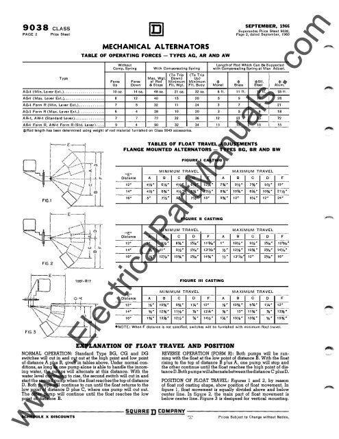
EXPLANATION OF FLOAT TRAVEL AND POSITION<br />
NORMAL OPERATION: Standard Type BG, CG and DG<br />
switches will cut in and cut out at the high point and low point<br />
of distance A plus B, given in tables above. Under normal conditions,<br />
as long as one pump alone is able to handle the incoming<br />
water, the pumps will alternate at this distance. With the<br />
water level continuing to rise, the second switch will cut in and<br />
start the second pump when the float reaches the top of distance<br />
D. Both pumps will continue to run until the float returns to the<br />
low point of distance D plus C, where one pump will cut out.<br />
The other pump will continue until the float reaches the low<br />
point of distance B.<br />
---- -- -- -- -- -- SQUARED<br />
REVERSE OPERATION (FORM R): Both pumps will be running<br />
with the float at the low point of distance B. With the float<br />
rising to the top of distance B plus A, one pump will stop and<br />
the other continue until the float reaches the high point of distanceD.<br />
Both pumps will alternate between the distance C plus D.<br />
POSITION OF FLOAT TRAVEL: Figures 1 and 2, by reason<br />
of float rod casting shape, show position of float movement. In<br />
figure 1, float movement is equally divided above and below<br />
center line. In figure 2, the main part of float movement is<br />
below center line. Figure 3 is designed for vertical mounting.<br />
I:DMPRNY ---- -- -- -- -- --<br />
www www . . <strong>Electrical</strong><strong>Part</strong><strong>Manuals</strong> <strong>Electrical</strong><strong>Part</strong><strong>Manuals</strong> . . com<br />
SCHEDULE X DISCOUNTS Prices Subject to Change without Notice.