www . ElectricalPartManuals . com
www . ElectricalPartManuals . com
www . ElectricalPartManuals . com

You also want an ePaper? Increase the reach of your titles
YUMPU automatically turns print PDFs into web optimized ePapers that Google loves.
W E S T I N G H 0 USE<br />
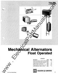
TYPE RR-7 REGISTER REGULATOR<br />
INSTRUCTIONS FOR INSTALLATION<br />
INSTRUCTION BOOK 5670-36-c<br />
(9-36)<br />
WESTINGHOUSE ELECTRIC AND MANUFACTURING COMPANY<br />
EAST PITTSBURGH WORKS EAST PITTSBURGH, PA.<br />
<strong>www</strong> . <strong>ElectricalPartManuals</strong> . <strong>com</strong>
o<br />
I<br />
U")<br />
v - SP ARE TUBES<br />
The following tubes should preferably be kept as mpares:<br />
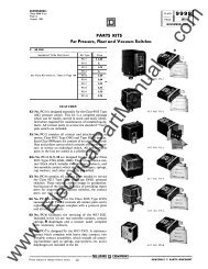
VI - RENEWAL PARTS<br />
One SK-60 phototubo<br />
One RJ-571 amplifier tube.<br />
One KU-627 or KU-636 grid glow tube.<br />
Name of Part<br />
Milliampere meter<br />
Potentiometer, 20,000 ohms<br />
Potentiometer dial<br />
KU tube socket<br />
RJ-571 tube socket<br />
Rectox Rectifier<br />
Transformer for 60 cycle<br />
* Transformer for 25 cycle<br />
Resistor tube<br />
Reactor<br />
Resistor 1 MEGOHM<br />
Resistor 500 ohms<br />
Resistor 0.25 MEGOHM<br />
Resistor 10,000 ohms<br />
Resistor 5 MEGOHM<br />
Capacitor AEROVOX 0.01 MF Type 284<br />
Capacitor AEROVOX 4 MF Type 407<br />
Capacitor<br />
Style<br />
818504<br />
846696<br />
8696f4<br />
7932 2<br />
8317 6<br />
9665 3<br />
t:<br />
943670<br />
850583<br />
860871<br />
9436,4<br />
861041<br />
799952<br />
829465<br />
-_ .......<br />
1014338<br />
* Specify as 25-cyc1e Transformer for Type RR-7 Register<br />
Regulator.<br />
<strong>www</strong> . <strong>ElectricalPartManuals</strong> . <strong>com</strong><br />
4.
WESTINGHOUSE ELECTRIC & MANUFACTURING COMPANY<br />
Business Addresses<br />
PARENT COMPANY<br />
Headquarters, East Pittsburgh, Pa.<br />
"AKRON, OHIO, 106 Sou.h Main St.<br />
'ALBANY, N. Y., 360 Broadway<br />
iALEXANDRIA, VA., 121 Frazier Ave.<br />
'ALLENTOWN, PA., 522 Maple S..<br />
"APPLETON, WISC., '1 Bellaire Court, P. O.<br />
Box: 206<br />
tAPPLETON, WISC., 1029 So. Ou.agamie St.<br />
"t'ATLANTA, GA., 426 Marietta St., N. W.<br />
·tFAIRMONT, W. VA., 602 Cleveland Ave.<br />
§FARGO, N. D., 319-12 Ave. N.<br />
'FORT WAYNE,IND., 1010 Packard Ave.<br />
"FORT WORTH, TEXAS, 501 Jones St.<br />
"GARY, IND., 101 WashingtOn St.<br />
"GRAND RAPIDS, MICH., 501 Monroe Ave.<br />
N. W.<br />
"GREENVILLE, S. C., Wen Earle St., P. O.<br />
Box 1591<br />
'PITTSBURGH, PA., 435 Seventh Ave.<br />
xtPITTSBURGH, PA., 543 N. Lang Ave.<br />
'PITTSBURGH, PA •• 3000 Liberty Ave.<br />
"PORTLAND. MAINE, 27 Deerfield Road,<br />
P. o. Box: 1797<br />
"PORTLAND, OREGON, 309 S. W. Sixth Ave.<br />
tPORTLAND, OREGON, 2138 N. Interstate<br />
Ave.<br />
xATTICA, N. Y. "HAMMOND, IND., 235 161th S.,<br />
'PORTLAND, OREGON. 720 N. ThompoOD<br />
'BAKERSFIELD, CALIF., 2224 San Emedio St. "HARTFORD CONN., Main &. Pearl Sra.<br />
St.<br />
"BALTIMORE MD., 118 E. Lombard St.<br />
tBAL TIMORE. MD., SOl East Preston Road<br />
IBALTIMORE, MD., 40 S. Calvert St.<br />
.... """ BEAUMONT, TEXAS, 2293 Broadway Ave..<br />
P. O. Box 2366<br />
'BIRMINGHAM, ALA., 2030 Second Ave.<br />
"BLUEFIELD, W. VA., 208 Bluefield Avenue,<br />
Box 8'18<br />
IBOISE, IDAHO, P. O. Box 1591<br />
"BOSTON, MASS., 10 High St.<br />
t.BOSTON, MASS., 12 Farnsworth St.<br />
"tBRIDGEPORT, CONN., Bruce Ave. &. Sey·<br />
xtHOMEWOob WORKS, Pittsburg!,.. Pa., 543<br />
N. Lang Ave.<br />
®'HOUSTON, TEXAS, 1314 Texas Ave.<br />
'HOUSTON, TEXAS, 2313 Commerce Ave.<br />
tHOUSTON, TEXAS, 2315 Commerce Ave.<br />
'f,HUNTINGTON, W. VA., 209 Ninth St.<br />
"INDIANAPOLIS, IND., 539 Madison Ave.<br />
lINDIANAPOLlS, IND., 551 West Merrill St.<br />
ISHPEMING. MICH., 433 High St.<br />
'JACKSON, MICH., 212 We .. Michigan Ave.<br />
"tJOHNSTOWN, PA. 47 Mes.enger St.<br />
"tIliKANSAS CITY, MO •• 2124 Wyandotte St.<br />
"KNOXVILLE.1. TENN., Gay &. Clinch St.<br />
"tPROVIDENCE, R. I" 16 Elbow St.<br />
"RALEIGH, N. C., 803 North Peraon St.<br />
IRALEIGH, N. C., 322 S. Harring.on St., P. 0,<br />
Box 911<br />
§READING. PA., 619 Spruce St.<br />
'RICHMOND, VA., Fifth &. Byrd<br />
tROANOKE, VA., 701 Carter Rd., Rale/llh<br />
Court<br />
"tROCHESTER. N. Y., 410 Atlantic Ave.<br />
'ROCKFORD, ILL., 130 South Second St.<br />
'SACRAMENTO. CALIF., 719 "K" St.<br />
"SALT LAKE CITY. UTAH, 10 Wes. Flnt<br />
South S •.<br />
mour St.<br />
"BUFFALO, N. Y., 814 Ellicott Square<br />
tlliBUFFALO, N. Y., 1132 Seneca St.<br />
'BURLINGTON, IOWA, P. O. Box 191<br />
"BURLINGTON, VER., 208 Park Ave.<br />
®" BUTTE MONTANA, 129 West Park Stteet<br />
"CANTON, OHIO, Market &. Tuscarawa. Sts.<br />
"t,CHARLOTTE, N. C., 210·East Sixth St.<br />
"LITTLE ROcK, ARK., 1115 West 24th St.,<br />
P. O. Box 1052<br />
tLiTTLE ROCK, ARK., % Fones Br05. Hdwe.,<br />
2nd &. Rock St ••<br />
"t'LOS ANGELES, CALIF., 420 So. San Pedro St.<br />
"LOUISVILLE, KY., 322 West Broadway<br />
"MADISON, WIse., 508 Edgewood Ave., P. 0,<br />
Box 228<br />
t,SALT LAKE CITY, UTAH, 346 A Pierpont<br />
Ave.<br />
fSALT LAKE CITY, UTAH, 23S W. S. Temple<br />
"SAN ANTONIO, TEXAS, 212 East Houston<br />
St.<br />
"SAN FRANCISCO, CALIF., 1 Monti/omery<br />
St.<br />
"SEATTLE, WASH .• 603 Stewart St.<br />
'CHATTANOOGA, TENN., 536 Market St.<br />
"CHICAGO. ILL •• 20 N. Wacker Drive, P. O.<br />
Box "bH<br />
t.CHICAGO, ILL, 2201 W. Pershing Road,<br />
P. O. Box 1103<br />
xMANSFIELD, OHIO, 200 East Fifth St.<br />
"MARSHALL. TEXAS. 202 W. Merritt St.,<br />
P. O. Box 412<br />
"MEMPHIS, TENN., 130 Madison Ave.<br />
"MIAMI FLA., 1036 N. Miami Ave., P. O.<br />
t.SEATTLE, WASH., 3451 East Marginal Way<br />
xSHARON, PA, 469 Sharpsville Ave.<br />
"SIOUX CITY, IOWA. 2311 George St.<br />
'SOUTH BEND. IND., 216 Ea .. Wayne St,<br />
§SOUTH BEND, IND., 107 E. Jefferson St.<br />
xCHICOPEE FALLS, MASSACHUSETTS<br />
·tIflCINCINNATI, OHIO, 207 West Third S..<br />
"txIliCLEVELAND, OHIO, 1216 We .. Fifty.Eighth<br />
St., Box 5811<br />
§COLUMBIA, S. C., 912 Lady St.<br />
'COLUMBUS, OHIO, Gay &. Third Su.<br />
Box 590<br />
"MILWAUKEE, WISC., 546 North Broadway<br />
tMILWAUKEE, WISC., 1669 N. Water St.<br />
"f' MINNEAPOLIS, MINN., 2303 Kennedy St.,<br />
N. E.<br />
'MONROE, LA., 1610 N. Fourth St.<br />
xSOUTH PHlLA. WKS., Essington, Pa.<br />
·SOUTH PHILA. WKS., P. O. Box 7348, PhIla.<br />
delphia, Pa.<br />
"SPOKANE, WASH., ISS Monroe St.<br />
'SPRINGFIELD, ILL., 130 So. Sixth St .. P. O.<br />
Box 37<br />
"DALLAS, TEXAS, 209 Browder St.<br />
'DALLAS, TEXAS, 1712 Carter St.<br />
'DAVENPORT, IOWA, 206 E. Second St.<br />
'DA YTON, OHIO, 30 North Main St.<br />
"DENVER, COLORADO, 900 Fifteenth St.<br />
iii DENVER, COLORADO. 1700 Sixteenth St.<br />
'NASHVILLE, TENN., 219 N. Second Ave.<br />
'NEWARK, N. J., 1180 Raymond Blvd.<br />
t,NEWARK, N. J., Haynes Ave. &. Lincoln<br />
High\Vy<br />
xNEWARK, N. J., Plane &. Orange St.<br />
'NEW HAVEN. CONN., 42 Church St.<br />
"tSPRINGFIELD. MASS., 395 Liberty St.<br />
xSPRINGFIELD, MASS., 653 Page Boulevard<br />
·ST. LOUIS, MO., 411 North Seventh St.<br />
t'ST. LOUIS, MO., 711 South Twelfth St.<br />
xST. LOUIS. MO., 3850 Bingham Ave.<br />
'SYRACUSE, N. y" 420 N. Geddes St.<br />
tDENVER. COLORADO, 2644 Walnut St. t'NEW ORLEANS. LA., 333 St. Charl.,. St.<br />
'TACOMA. WASH., 1023 "An St.<br />
xDERRY, PA.<br />
(D°DES MOINES, lOW A, 523 Sixrh Ave.<br />
"t,DETROIT, MICH .• 5757 Trumbull Ave.<br />
.NEW ORLEANS, LA., 527 Poydra. St.<br />
®'NEW YORK, N. Y., ISO Broadway<br />
tNEW YORK, N. Y., 460 West Thirty·Fourth St.<br />
'TAMPA, FLA., 417 EUamae Ave.<br />
"TOLEDO, OHIO. 245 Summi. St.<br />
*TULSA, OKLA., 303 East Brady St.<br />
'DULUTH, MINN., 10 Ea" Superior St.<br />
"EASTPORT, ME., p, o. Box 764<br />
'ELMIRA, N. Y., 338 Eas. Water Sr.<br />
"NIAGARA FALLS, N. Y., 205 Falls St.<br />
"NORFOLK, VA., 254 Tazewell St.<br />
'OKLAHOMA CITY, OKLA., 10 E. CalIfornia<br />
·tUTICA. N. Y., 113 N. Genesee St.<br />
"WASHINGTON, D. C., 1434 New York Ave.,<br />
N. W.<br />
"El PASO, TEXAS, 303 N. Oregon St. St.<br />
"WATERLOO, IOWA, 328 Jefferson St., P. O.<br />
IfIEL PASO. TEXAS, 4SO Canal St.<br />
tEL PASO, TEX., 'A> lork Hdwe. Co., 309 N.<br />
ElPaso St.<br />
f'EMERYVILLE, CALIF., 5815 Peladeau St.<br />
tEMERYVILLE CALIF lA££ P 11 S<br />
xEMER YVILLE, CALIF., 6161 Green St.<br />
"ERIE, PA .. 1003 State St.<br />
.OKLAHOMA CITY, OKLA., Third &. Alie<br />
Sr •.<br />
'OMAHA, NEB., 409 South Seventeenth St.<br />
iOMAHA, NEB., 117 N. nth St.<br />
'PEORIA, ILL, 104 E. State St.<br />
"fIliPHILADELPHIA, PA., 3001 Walnut St.<br />
'PHOENIX, ARIZONA, 11 West Jefferson St.<br />
xPITTSBURGH, PA., Nuttall Works, 200 Me:-<br />
Box 416<br />
'WICHITA, KAN., 400 South Emporia Sr.<br />
·fWILKES·BARRE, PA .• 267 N. l'ennsylvanla<br />
Ave.<br />
·tWORCESTER. MASS., 32 Sourhbrldge 5
Business Addresses-Continued<br />
WESTINGHOUSE ELECTRIC ELEVATOR COMPANY<br />
"AKRON, OHIO, 106 S. Main St.<br />
"BOSTON, MASS., 10 High St.<br />
'BUFFALO, N. Y., 826 E!licott Sq. Bldg.<br />
IxCHICAGO, ILL., 1500 N. Branch St.<br />
"CHICAGO, ILL •• 222 No. Bank Drive<br />
"CINCINNATI, OHIO, Third &. Elm Sts.<br />
"CLEVELAND, OHIO, 1006 Rockefeller Bldg.<br />
"COLUMBUS. OHIO, Gay &. Third Sr.<br />
• "DALLAS, TEXAS, 209 Browder St.<br />
(j)'DES MOINES, IOWA, 523 Sixth Ave.<br />
_"DETROIT, MICH., 5757 Trumbull Ave.<br />
"DUBUQUE, IOWA, 312 Seminary St.<br />
(j)"JACKSON. MISS., 249 N. Preti .. St.<br />
"KANSAS CITY, MO., 2124 Wy andotte St.<br />
*LOS ANGELES, CALIF., 420 So. San Pedro Sr.<br />
'NEW YORK, N. Y., 30 Rockefeller Plaza<br />
""PHILADELPHIA, PA., Thirtieth &. Walnut<br />
St>.<br />
"PHOENIX, ARIZONA, 66 E. Hoover Ave.<br />
t*PITTSBURGH, PA., 435 Seventh Ave.<br />
'ST. LOUIS. MO .. 411 North Seventh St.<br />
_ST. LOUIS, MO., 717 S. Twelfth St.<br />
"SAN FRANCISCO, CALIF., 1 Montgomery<br />
St.<br />
_SAN FRANCISCO, CALIF .. 741 Natoma St.<br />
'SEATTLE, WASH., 603 Stewart St.<br />
"WASHINGTON, D. C .. 1209 Eye St., N. W .<br />
WESTINGHOUSE ELECTRIC INTERNATIONAL' COMPANY<br />
(j)zNEW YORK CITY, N. Y., 150 Broadway<br />
'LONDON, W. C. 2, ENGLAND, 2 Norfolk<br />
St., Strand<br />
(j)'SYDNEY, AUSTRALIA, Box 263+EE, G.P.O.<br />
(j)'RIO DE JANEIRO, BRAZIL, Caixa Postal 687<br />
'SANTIAGO, CHILE, Casilla 1897<br />
(j)'SHANGHAI, CHINA, P. O. Box 959<br />
"MILANO, ITALY, Piazza Crispi 3<br />
'WELLINGTON, NEW ZEALAND, 19·23<br />
Blair St.<br />
• • A TI.ANT A, GA., 426 Marietta St.<br />
'BALTIMORE, MD., 118 E. Lombard St.<br />
xBELLEVILLE, N J., 720 Washington Ave.<br />
.. ,BLOOMFIELD, N. J .. Cleameld Ave.<br />
"BOSTON, MASS., 10 High St.<br />
III BOSTON, MASS., 12 Farnsworth St.<br />
"BUFFALO, N. Y., 295 Main St.<br />
"CHICAGO, ILL., 20 North Wacker Drive<br />
,CHICAGO, ILL., 2201·2221 W. Pershing Road<br />
'CINCINNATI, OHIO, Third &. Elm Su.<br />
'CLEVELAND, OHIO, 1216 W. 58th St.<br />
*COLUMBUS, OHIO, Gay &. Third St.<br />
(j)'DALLAS, TEXAS, 209 Browder St.<br />
iii DALLAS. TEXAS, 11 18 Jackson St.<br />
-DA VENPOR T, IOWA. 209 Eao< Second St.<br />
'DENVER, COLO., 910 Fifteenth St.<br />
"DES MOINES. IOWA. 218 West Second St.<br />
"'DETROIT, MICH., 5757 Trumbull St.<br />
(j)'LIMA, PERU, Edilido Wiese, S. A.<br />
Esquina Nunez y Filipina.<br />
(j)*MANILA, P. I., P. O. Box 998<br />
'SAN JUAN, Puerto Rico, P. O. Box 1539<br />
'CIA. WESTINGHOUSE INTERNACIONAL<br />
S. A., Avenida de Mayo 1035, Bue nos Aires,<br />
Argentine<br />
·CIA. WESTINGHOUSE ELEC. DE CUBA,<br />
Cane Jose de San Martin No •. 16 y 18, Apar.<br />
tado 2289. Havana, Cuba<br />
WESTINGHOUSE LAMP COMPANY<br />
"EMERYVILLE, CALIF., 1446 Powell St.<br />
@*HOUSTON, TEXAS, 1314 Tex.s Ave.<br />
·HUNTINGTON. W. V A" 209 Ninth St.<br />
-INDIANAPOLIS, IND., 539 Madison Ave.<br />
_"KANSAS CITY, MO., 2124 Wyandotte St.<br />
iii 'LOS ANGELES, CALIF .• 420 S. San Pedro St.<br />
'LOUISVILLE, KY .. 332 West Broadway<br />
"MEMPHIS, TENN., 130 Madison St.<br />
°MIL W AUKER, WISC., 534·546 North Broadway<br />
'MINNEAPOLlS, MINN., 2303 Kennedy St.,<br />
N. E.<br />
iii-NEW ORLEANS. LA., S16 Howard Ave.<br />
(j)yNEW YORK, N. Y., 150 Broadway<br />
"OKLAHOMA CITY, OKLA •• 10 E. California<br />
Sr.<br />
'OMAHA, NEB., Seventeenth &. Harney Su.<br />
"PHILADELPHIA, PA .. Thirtieth &. Walnut<br />
Sts.<br />
WESTINGHOUSE X-RAY COMPANY, INC.<br />
"WESTINGHOUSE ELEC. CO. OF INDIA.<br />
Feltham House, Graham Road, Ballard<br />
Eatate, Bombay, India<br />
·CIA. WESTINGHOUSE ELEC. INTERNA.<br />
ClONAL Edifido la National Apartado<br />
78-Bis. Mexico, D. F. Mexico<br />
'WESTINGHOUSE ELEC. CO. OF SOUTH<br />
AFRICA, LTD., P. O. Box 6067, Johanm".<br />
butg, South Africa<br />
"PITTSBURGH, PA., 435 Seventh Ave •<br />
"'PITTSBURGH, PA., Try St. & Terminal Bldg.<br />
(j)*RICHMOND, VA., 700 Franklin Street<br />
'ROCHESTER, N, Y., 240 St. Paul St .<br />
'SALT LAKE CITY, UTAH, 10 West Fim St.<br />
'SAN ANTONIO, TEXASJ<br />
,<br />
212 E. Houston St.<br />
'SAN FRANCISCO, CALI!:'., 1 Mon ery St.<br />
'SAN FRANCISCO, CALIF., 60 al St.<br />
'SEA TILE, WASH., 603 Stewart<br />
(j)ISEATTLE, WASH., 3451 East Marginal Way<br />
·ST. LOUIS, MO., 411 No. Seventh St.<br />
(j)IST. LOUIS, MO., 717 So. 12th Street<br />
(j)'SYRACUSE, N. Y., 109 So. Warren Street<br />
'TOLEDO, OHIO, 245 Summit St.<br />
xTRENTON, N. J., 400 Pennington Ave.<br />
'WASHINGTON, D. G. 1434 N, Y. Ave.,<br />
N. W.<br />
'YOUNGSTOWN, OHIO, 25 E. Boardman St.<br />
"ATLANTA, GA .. 565 W. Peachtree St., N. E. f"DETROIT, MICH., 5757 Trumbull Ave.<br />
'NEW YORK. N. Y., 173 E. Ehthty·Seventh St.<br />
'BALTIMORE, MD., 118 Ea .. Lombard St.<br />
'BOSTON, MASS., 270 Commonwealth Ave.<br />
• xLONG ISLAND CITY, N. Y., 21·16 43rd Ave.<br />
'LOS ANGELES, CALIF., 420 S. San Pedro Sr.<br />
"OMAHA, NEB., 117 N. Thirteenth St .<br />
"PHILADELPHIA. PA .. 3001 Walnur St.<br />
'CHICAGO, Ill .. 512 S. Peoria St.<br />
'MIL WAUKEE, WISC., 534 North Broadway<br />
'PITTSBURGH, PA., 3710 Fifth Ave.<br />
'DALLAS, TEXAS, 335 N. Sr. Paul St. "NEW ORLEANS, LA., 333 St. Charles St.<br />
'SAN FRANCISCO, CALIF., 870 Marlcet St.<br />
BRYANT ELECTRIC COMPANY WESTINGHOUSE RADIO STATIONS<br />
"BOSTON, MASS., 10 High St.<br />
zxBRIDGEPORT, CONN., Main Plant, 1421 State St.<br />
(j)xBRIDGEPORT, CONN., Plastics Division Plant, 1105 Railroad Ave.<br />
'IIICHICAGO, ILL., 844 West Adams St,<br />
'NEW YORK, N. Y., 100 East Forty·Second St.<br />
"'SAN FRANCISCO, CALIF., 325 Ninth St.<br />
"Salea OIIice tService OIIice<br />
®Changed or added .inee previous issue.<br />
R·S16<br />
STA TION KDKA, 310 Grant Sr., Pittsburgh, Pa.<br />
STATION WBZ, 271 Tremont St., Boston, Mass.<br />
STATION KYW. 1622 Chestnut St., Philadelphia, Pa.<br />
STATION WBZA, Hotel Kimball, Springfield, .Mas •.<br />
CANADIAN WESTINGHOUSE COMPANY, LIMITED<br />
@*tlCALGARY, 320 Eighth Avenue West, Calgary, Alberta, Can.<br />
,"EDMONTON, 10127, lO4rh St., Armstrong Block, Edmonton, Alberta, Can.<br />
,"FORT WILLIAM, Cuthbertson Block, Fort William, Ontatio, Can.<br />
(j)#*HALIFAX, 158 Granville St., Halifax, Nova Seorla, Can.<br />
(j)xz*HAMILTON, Hamilton, Ontario, Can.<br />
(j)'MONTREAL, 1135 Beaver Hall Hill, Montreal, Quebec, C)ln.<br />
(j)MONTREAL, 400 McGill St<br />
:,t<br />
Momreal, Quebec, Can .<br />
(j)tMONTREAL, 1844 William :::o r., Montreal Quebec, Can.<br />
'OTT A W A, Ahearn &. Soper Limired, P. O. Box 415, Ottawa, Ontario, Can.<br />
"UREGINA, 2408 Eleventh Ave., Regina, SasKarchewan, Can.<br />
(j)'HTORONTO, 355 King St. West, Toronto, Ontario, Can.<br />
CD'VANCOUVER, 1418 Marlne Bldg., Vancouver, B. C .. Can.<br />
(j)t#VANCOUVER, 1090 Homer St., Vancouver, B. C., Can.<br />
(j)f*fWINNIPEG, 158 Portage Ave. East, Winnipeg, Manitoba, Can.<br />
xWorks • Warehouse zHeadquanera yExe
( )<br />
<br />
4<br />
.s-<br />
.<br />
7<br />
8<br />
S<br />
I/J<br />
1'1<br />
/z<br />
/.JI<br />
14-<br />
1..5<br />
,OIA<br />
"._ .... _,... .,. .... 1<br />
B"p;. Ik.IIE<br />
B!i!WII"<br />
Y£l.l.t"iI/<br />
GREEN<br />
Rep<br />
WN/T£<br />
81.ve.<br />
&RCk<br />
(iii' E.IiII. YE#tY<br />
(l (l<br />
PI?NJ!!.I- (FKIINT 'l/6.W) PI9It1£L. CR£HN VIEW)<br />
WT£<br />
eH('.J'EI./.DW ,."..<br />
SV)"<br />
rEI. I. ow<br />
{'iEl)<br />
11/<br />
L<br />
<br />
Ct.lpr#<br />
---- -j<br />
- _._ ... -<br />
I<br />
8 TIIPO"<br />
I({/, 'Tulill£<br />
. .<br />
<br />
.¥o' ,.#<br />
7fiI'}"4 uP<br />
..., .. ill .... ,,'1> IJ.tN'RI UlIIIS)<br />
'/ICk·Nl)rl.<br />
'. ,. .... T<br />
0'" .. {.",. 'I1IfJfM.,1<br />
.s<br />
7A"#KS.<br />
1-/--' '1111 -flf...!<br />
I LJ<br />
R£IICT(JR.<br />
J<br />
. . '<br />
e,8. I<br />
'J-=HtA<br />
I "J.. I<br />
:. 6,",,'N'Af'De""'N'J). r -':{-... ... 3. q tt-l.
(,<br />
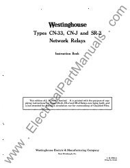
TYPE RX PHOTOTROLLER<br />
Instructions for Installation<br />
Figure 1 The Type RX is Intended for General Purpose<br />
Industrial Applications.<br />
Westinghouse Electric and Manufacturing Company<br />
East Pittsburgh, Pa.<br />
Printed in U.S.A. (6-38) I.B. 5670-43<br />
<strong>www</strong> . <strong>ElectricalPartManuals</strong> . <strong>com</strong>
'.<br />
..<br />
.<br />
Preface<br />
, : ;<br />
o Ii<br />
List of Applications - - -<br />
t ,' ,' ,.:,, : , , , ',, ' ""<br />
.<br />
'<br />
.,; . ,.. , ' . . '" ., .... ;<br />
.. '-<br />
. ",' ::::1i::;l,.(" · , t<br />
. .<br />
. . " <br />
: . " , ,, ' , "' .:<br />
:Westinghous _ Type, :\RX 'Plt9proller<br />
INDEX<br />
How to Select and Apply Phototrollers - - -<br />
Phototube Housings<br />
Light Sources - - - - - - -<br />
Principle of Operation<br />
Installation<br />
What to do if Phototroller Does Not Operate<br />
Satisfactorily-<br />
"Figure<br />
"<br />
,.....<br />
.-.<br />
LIST OF ILLUSTRATIONS<br />
1 The Type RX Phototroller. - - - - - - - -<br />
3<br />
4<br />
5<br />
6<br />
7<br />
Curve Showing Minimum Illumination as a<br />
Function of Maximum Illumination and Per<br />
Cent A-C Voltage Variation. - - - - - - -<br />
Type RX Phototroller. Diagram of Connections.<br />
- - - - - - - - - - - - - - -<br />
Control Voltage Characteristics.<br />
Calibration Curve. -<br />
- - - - -<br />
Outline 'rype RX Phototroller (60<br />
Outline 'rype RX Phototroller (25<br />
,", '<br />
' -. ,<br />
t<br />
..<br />
",':<br />
- -<br />
Sf ;<br />
' .<br />
- - -<br />
- -<br />
cycle)<br />
cycle)<br />
, t<br />
';'1."<br />
:;:<br />
-<br />
-<br />
-<br />
-<br />
-<br />
' ..<br />
Page<br />
<strong>www</strong> . <strong>ElectricalPartManuals</strong> . <strong>com</strong><br />
,3<br />
<br />
4<br />
<br />
6<br />
6'<br />
7<br />
10<br />
13<br />
14<br />
"15<br />
15<br />
16<br />
17<br />
."'.' .-' ..<br />
:",<br />
"./ ,i.;.' ;, :e"';,';.:"']<br />
; "<br />
\<br />
" ',1 , "<br />
, "<br />
:.<br />
I ,<br />
' ,, . '<br />
,
. .<br />
. . , "<br />
:.' "<br />
A<br />
>c"<br />
. ,<br />
, :;<br />
•<br />
'c<br />
"<br />
. .<br />
.<br />
,, '<br />
"<br />
.' '<br />
•<br />
:. , '. , . . '<br />
l\r"'Iil!.r.¥" ""j'-''''''dli:!l'<br />
, . .<br />
l. , .), , 3:, . ,,'"<br />
of' , ,< ",;;\' "<br />
"', Door . Opening : '- "boriiritie&' : ;', ,'; "<br />
....<br />
. '<br />
.<br />
J.I" . .. ,\. ' I.,;, --:-n-" ''':-'f(' <br />
, ' T} ;:;:/ }' '<br />
.<br />
; ; :: .:.':g" "'T{: if?:<br />
. ," ,"' .... : .<br />
'.' • ;. '. ,<br />
' ,,; 14_: ••<br />
. ." '<br />
, .' We !3ti:qgh.ous ., TY1)(;'P '<br />
RX ,ptotr.ol er .<br />
'-: . ' . .' ·: : :f ' : ;b.' ',¥<br />
. , . " • ),; .:t \. ': , : .. ' III i .. -.: t .<br />
, . '"<br />
.<br />
·.- ><br />
: l' •<br />
. ' • • .. ,Z·o ,-: . " ; '"<br />
.<br />
', ,',<br />
.:"._.:'. , ,'<br />
· . 1':<br />
· . ':,;.; .<br />
"<br />
- . v,. ... !, • .' f. . • •<br />
•<br />
'.. •<br />
, .... :. . ". '<br />
"'.' , ,'.. .<br />
\ ' . At the maximum. pe'ed .o.f opert,ion, at··c least 0.2 ·;;s·e'conds! .:;.:,.<br />
. : t : .. '.<br />
. . > . . # \01 . ' #; • (<br />
should' be : , allowed oetvteen' the centors of impulse.s',,-core:·spond.- .<br />
ing ·to. 300 operations per m.1nute. In order tt thiS:' humb '<br />
'<br />
i'<br />
'of operations POI' min.ute ma'$" be Qptained, the "antl',and t1;off" :";, .<br />
. intervals shoulct. :be· equal'.,;Howev:r,. the .approximat. ,mi:n:bnum'<br />
time of light change requ.1.rl§d· 'to ':or.ate the'.relayt:i:·: apout., 'l<br />
: .;:<br />
. ,.<br />
, . . 0.05 second • .<br />
The maximum'·.J;'e<strong>com</strong>ntended rate of. opeNj:tio:l's : " :<br />
. 150 pe r millu te ". . . ':' . ,.;. ' ,': .<br />
, :.;,.: ,<br />
If the. phototube 'is ':hlOlnted:an a separatehQU81ng,..:1:t· .. :{ . ',.<br />
may be located up .to 25 c.able·, feet; distant, aithoughstandard r .. .<br />
. housings.ar furnished wi'tlf:,1;O fet of'cable, 'l-fh,ich,ls usually',' ':;:\:<br />
suffiient. , Distances beyond 10 ·feet 'slow down ,·the ,pespons.e . ,'" .<br />
'25%, and . longer times tJ:1a:n' :.those given for ope.rtio!l; must' ' .: ,<br />
;':\ t:<br />
allowed. The. 'footcandle r4tins" of the unit is then also in:<br />
'creased to 6.5, footcandlei;L '<br />
, .<br />
E>.?fetl Control for;<br />
Elev'ator d0ors· , .<br />
.Pulverized fuel fur.l1..a.ces '. : '. : L<br />
.:<br />
Punch, prsses" : ' ,<br />
Railroaa crossings .P. idustril sidings<br />
(2) HOW Tel SELECT ::AN. APPLY PHOTO-_TROLLER§<br />
,<br />
The first· . fundamental in apPlicBrtion Of' PhMiotroli.ercfk .<br />
.'<br />
• •<br />
"f'<br />
':1ction. . <br />
.<br />
, t ",'" : ••••<br />
'"<br />
. . ... ! ' .<br />
.<br />
<br />
. . ' ....<br />
"<br />
" .<br />
. .<br />
. ,<br />
' .4 , '.<br />
. .. .<br />
<strong>www</strong> . <strong>ElectricalPartManuals</strong> . <strong>com</strong><br />
,<br />
. " i' ...<br />
;,,{', c, ,.,\'.::.:.-,- ....<br />
.. ..<br />
.. .i..-,.:..."..;.,.:.,.;,, . ..;i,,,;,,;';' ,;;;,<br />
,<br />
'. ' ..<br />
.<br />
',>'<br />
*_
Ii , ,' t ,<br />
\<br />
.C<br />
st1nghouse Type RX PhototrolJer<br />
Transmission is varied by arranging an opaque, partially<br />
opaque, ob ject to intercept 1;.he beam of light which normally<br />
passes from light source to phototube. This is the most <strong>com</strong>mon<br />
method of operation ,and may be used for automobiles, people,<br />
paper sheets, steel sheets, packages, etc. Clear cellophane is<br />
obviously not very opaque and, therefore, does not vary the light<br />
beam much wheh intercepted by it. When operating with material<br />
of this nature whose capacity is not high, it is very important<br />
to Jmow what :this capacity is. Such application's are usually<br />
more difficult and it is re<strong>com</strong>mended that they be referred to<br />
the nearest district office of the Westinghouse Company for<br />
re<strong>com</strong>mendatiohs.<br />
Refle,ction is varied by arranging the optical system so<br />
that the light beam is reflected from the material to the phototube<br />
and the extent of this ret"lection is varied by the character<br />
of the surface of the material.<br />
The RX ?hoto-troller does not have sufficient sensitivity<br />
for most reflected light applica.tions and, therefore, should<br />
not be used for this purpose. The RX-l Photo-troller, however,<br />
is specially desgned for reflected light applicat'ions.<br />
The aetua.l procedure to be used in selecting the proper<br />
photo-tollers and light, source is:<br />
1 - Determine what portion of the light beam will be<br />
available under maximum illumination conditions<br />
2 - Determine what portion of the illumination will' '<br />
be intercepted by the controlling object.<br />
3 - Select a photo-troller having the general characteristics<br />
desired, and then<br />
4 - Select" a <strong>com</strong>bination of photo-troller and light<br />
source such that at the distances and oerating,<br />
conditions determined under paragraphs (I) and (2),<br />
adequate sensitivity will be obtained.<br />
5 - Re-check all variable factors to make certain<br />
that adequate safety margin is provided in the<br />
<br />
se lectiqn.<br />
; ( 3) PHOTOTUBE HOUSINGS<br />
The RX Photo-troller is &rr anged so that the phototube<br />
may be mounted inside the case. When this is done the Jmockout<br />
in. the case door should be pressed out to permit the light to<br />
r.each the phototube. In many applications it is preferable to<br />
mount the phototllbe in a separte housing, and for this purpose<br />
one of the housings shown in attached Price List 18-315 should<br />
be used.<br />
<strong>www</strong> . <strong>ElectricalPartManuals</strong> . <strong>com</strong><br />
5 -<br />
•<br />
. '<br />
i' _.,.;J'-<br />
'I -;<br />
.-' . '<br />
,<br />
"
\<br />
.C<br />
.C<br />
"<br />
(4) LIGHT SOURCES<br />
(S)<br />
Various types of light sources are shown in attached<br />
Price List 18-316 all of which, except the type L, can be<br />
used with the Type RX Photo-troller. In selecting the light<br />
source care must be taken that the minimum illumination on<br />
the photo-tube must not exceed the values given in fig. 2.<br />
In this figure are shown different scales for the<br />
maximum illumination for different percentage changes in<br />
a-c line voltage. Using, for example, the basic 2% curve<br />
it is seen that if the maximum illumination is 30 foot<br />
candles, the minimum illumination must not exceed 15 foot<br />
candles. If, however, the maximum line voltage variation<br />
is 20 per cent and the maximum illumination is 30 foot candles<br />
at maximum a-c voltage, then the minimum illumination<br />
10 foot candles is found by following the circle from A to<br />
B, then to C and D.<br />
By using tho curves in fig. 2 in <strong>com</strong>bination with the<br />
light source curves in fig. 7 of Price List 18-316, the percentage<br />
reduction in light required can be determined.<br />
x8.mp1<br />
Light Source Type F.<br />
Voltage Variations 10%.<br />
Operating Distance 10 feet.<br />
From fig. 7 Price List 18-316 is found: 17 F.C.<br />
From fig. 2 ; 17 F.C. at 10% voltage variation gives<br />
7.5 F.C. minimum illumination.<br />
Consequently: Illumination must be reduced from<br />
17 F. C. to 7.5 J:il. C. or 56%.<br />
I t<br />
PRINCIPLE OF OPERATION<br />
The schematic diagram, for the type RX photo-troller<br />
is shown in fig. 3. The photo-troller is equipped with a<br />
type WL-629 Thyratron tube which is controlled by a type<br />
WL-735 phototube. The WL-629 tube is a gasf'i11ed discharge<br />
tube consisting of an anode connected to lS in fig. 3, a<br />
heater winding connected to leads 8 and 10, a cathode con<br />
.<br />
nected to Lead 8J and a control grid connected to the S<br />
MEG. resistor. The characteristics of the WL-629 tube are<br />
such that when the grid has a negative potential exceeding<br />
approximately 6 volts relative to the cathode the tube does n<br />
not be<strong>com</strong>e ionized, and no current is conducted through the<br />
tube. If the grid potential is made more positive, the<br />
tube breaks down,and conducts rectified current through<br />
relay coil I during the half cycles when lead 7 is positive<br />
in relation to lead 8.<br />
_<br />
6 _<br />
<strong>www</strong> . <strong>ElectricalPartManuals</strong> . <strong>com</strong><br />
, c
tt .' \ ,,,<br />
" <br />
-<br />
"<br />
Westingos Type RX Phototroller<br />
The grid control voltage as shown in fig. 3 consists<br />
of the a-c voltage <strong>com</strong>ponent between leads 8 and 13,<br />
obtained by means of the phase shift circuit consisting of<br />
resistor 9- 13 and capacity 8-13, and the d-c voltage <strong>com</strong>ponent<br />
C-13. Voltage 8-13 is advanced 135 degrees relative<br />
to voltage 8-7. The d-c voltage <strong>com</strong>ponent C-13<br />
changes its magnitude and polarity when the illumination<br />
on the phototube is varied, so that C is positive in relation<br />
to 13 when the degree of illumination on the phototube<br />
is high, and be<strong>com</strong>es negative when the illumination<br />
on the phototube is decreased.<br />
In fig. 4 are shown the relation between the various<br />
control voltages. The curve Ec is the characteristic grid<br />
control curve for the WL-629 tube. In order .to make the<br />
tube conduct current the instantaneous grid voltage must<br />
be more positive than shown by this curve. The grid control<br />
voltage as shown consists of the constant a-c voltage<br />
8-13 superimposed on the variable d-c voltage C-13.<br />
In the position shown voltage E<br />
g intersects voltage Ec at<br />
A, and at this point, therefore, the tube breaks down and<br />
conducts current during the remainder of the half cycle of<br />
voltage EA- If now voltage C-13 be made more negagive by<br />
decreasing the illumination on the phototube, voltage<br />
curve Eg is moved down so that the curve does not intercept<br />
the critical grid voltage curve E<br />
c<br />
' For this reason<br />
the WL-629 tube will not conduct current and the relay<br />
connected in series with the tube will be deenergized.<br />
(6) oup.ting<br />
(7)<br />
INSTALLATION<br />
Mount th e Photo-troller with the panel in a vertical<br />
position. If the phototube is to be mounted inside the<br />
Photo-troller case remove the knockout in the case door to<br />
permit light to reach the phototube. If the phototube is<br />
mounted in a separate housing, the housing may be mounted<br />
in any convenient position, up to 10 cable feet distant<br />
from the Photo-trolle.r, or 25 cable feet if the Phototroller<br />
is derated as outlined in paragraph 1.<br />
The light source may be mounted in any position except<br />
that the lamp base must not be higher than the lamp filament.<br />
Temperature Lim<br />
The Photo-troller should be mounted in a location<br />
where the ambient air temperature does not exceed 1100 F.<br />
If the Photo-troller is mounted near furnaces or other equipment<br />
radiating an excessive amount of heat, the Phototroller<br />
should be shielded by means of a suitable shield.<br />
The maximum air temperature at the location of the phototuoe<br />
housing should not excead 1500 F.<br />
<strong>www</strong> . <strong>ElectricalPartManuals</strong> . <strong>com</strong><br />
- 7 -<br />
\ .
I-'<br />
..jlo.<br />
f)<br />
l. <br />
--<br />
P,..,NEI.. _ (HE,,!R V/£W) , WIRING TA81..<br />
. 2"f ", f-;;; COI.O..R CO. LO<br />
..--- --/S" U I U ' .1<br />
I I REI) 1 .. :1" P:4TRIA...<br />
(-)<br />
7 t IJLI"'ICI1'-lf'fD TIf" 14! ?'q IRli_<br />
1f'£C'rc;c<br />
-' KfD -lJ/. I"'IC I't"<br />
Ii!.<br />
4 BLI"fCK<br />
S BlUE<br />
VNC'''''64£<br />
/"{)S 7#/5-<br />
,,.-<br />
ldAlOL"<br />
C:-o/vOVlr<br />
L""nl'"<br />
•<br />
I<br />
!<br />
I<br />
I<br />
I<br />
i<br />
I<br />
i<br />
I<br />
, I<br />
t-: I<br />
I<br />
I<br />
;<br />
I<br />
I<br />
I I<br />
-r<br />
!<br />
:<br />
I<br />
I I<br />
,<br />
i I<br />
I I I<br />
; i<br />
I<br />
I<br />
,<br />
!<br />
!<br />
,<br />
-<br />
I<br />
I I I<br />
I<br />
I<br />
I<br />
I I<br />
J<br />
I<br />
1<br />
I<br />
I<br />
I<br />
I<br />
I<br />
I<br />
I<br />
I<br />
I<br />
Wes tinghous e Type RX Phototroller<br />
I<br />
I<br />
,<br />
I<br />
I<br />
... I<br />
i<br />
i<br />
' I<br />
I ' I<br />
i i<br />
; j<br />
Fig. 4 Cont.rol Voltage Ch'aracteris tics<br />
" i<br />
i I !<br />
,. I<br />
i'.:)h<br />
"<br />
.<br />
'"<br />
t::<br />
iV, <br />
l'"t<br />
,( ..<br />
,\:<br />
!'"<br />
!-t.<br />
! -<br />
\,;<br />
"<br />
,-<br />
l-H- ·-tt+i<br />
"<br />
·t· T'-'<br />
."W<br />
'r.-<br />
+-<br />
I-t- 1-1<br />
1<br />
- - i\..<br />
..<br />
,. ,<br />
"<br />
I'-<br />
. --r-<br />
...<br />
I J.- "-<br />
I<br />
"<br />
.1<br />
I<br />
I<br />
"-<br />
'\.<br />
- \..'<br />
"-<br />
,<br />
I I<br />
, <br />
<br />
I 1 I<br />
," t-H<br />
I<br />
I<br />
10'"' i IA 101 iJ: <br />
I ...<br />
,<br />
-1 I" ,<br />
-v "0/ "11), t/".. III l"l<br />
b '"<br />
!""<br />
1<br />
!<br />
I<br />
+f=='"<br />
I I I<br />
I I<br />
Ll<br />
,il<br />
II' r lId."" ll;<br />
..J. "" .<br />
' " 140 I"" I'" 1"',"1"'<br />
I I<br />
II i<br />
IL<br />
Fig 5 Calibration Curve<br />
15<br />
I<br />
I<br />
'" , .-II"" ,.- +-<br />
,,,. In<br />
I"" 1"'""<br />
I<br />
I<br />
I<br />
,<br />
"<br />
I<br />
I I<br />
I I<br />
I<br />
- 1-1-<br />
<strong>www</strong> . <strong>ElectricalPartManuals</strong> . <strong>com</strong><br />
I<br />
,+ I
Fig. 1 - Type EM-I Photo-Troller with Long<br />
Focusing Tube - Cover Closed<br />
Application<br />
The Westinghouse 1ype RM-l Photo-Troller<br />
for heater control meets the requirement for a<br />
truly industrial device which operates from the<br />
light emitted from a piece of hot metal While being<br />
heated electrically. 1he light from the metal<br />
falls on a phototube controlling an amplifier<br />
tube, which in turn actuates a Thyratron tube<br />
directly. The Thyratron tube operates a contactor<br />
whose contacts will carry several amperes.<br />
1he equipment automatically shuts off the power<br />
supply to a heater. Since the amount of light<br />
emitted is proportional to the temperature of the<br />
metal, the Photo-Troller can be arranged to trip<br />
the power supply at a predetermined temperature.<br />
Provisions are included in the Photo-Troller to<br />
lock out the power cireuit immediately after the<br />
metal reaches the proper temperature and the operation<br />
is reinitiated only when the operator<br />
has put in a.new piece of metal and depressed a<br />
starting button manually.<br />
-<br />
Type RM·l Photo-Troller<br />
Instructions for Operating<br />
1<br />
Description<br />
,<br />
I. B. 5670-50<br />
The equipment is mounted in a sheet<br />
metal cabinet. The apparatus mouned in the<br />
cabinet consists of one RJ-571 amplifier tube,<br />
one KU-636 Thyratron tube and two 2-pole contactors.<br />
In addition, there is a phototube mounted<br />
on the lower end of the panel and facing toward<br />
the lens assembly. Sometimes the phototube and<br />
lens assembly is mounted remote from the cabinet.<br />
Behind the panel are located a transformer, rectifiers.<br />
capacitors, and other auxiliary parts.<br />
Extending from the bottom of the cabinet is a<br />
sight tube having mounted on its outer end a lens<br />
and a pr otective glass over the lens. On the<br />
front cover of the unit is mounted a pushbutton<br />
for emergency tr ip, a star t,pushbutton, a potentiometer<br />
for adjusting the operating points, and<br />
a dial to allow resetting of the equipment to a<br />
previously determined operating point.<br />
Installation<br />
The Photo-TrOller must be mounted vertically<br />
in order to keep the relays in the proper<br />
operating. position. The mounting of the Photo<br />
Troller should be as rigid as possible to insure<br />
fixed alignment of the optieal system.<br />
Fig. 2 Type B Phototube Housing<br />
The Photo-Troller will not be injured by<br />
any vibration which does not mechanically damage<br />
the apparatus,although vibration should be a minimum<br />
at the point of installation. The KU-636<br />
Thyratron tube which is supplied with-the Photo<br />
Troller is not affected by temperature changes and<br />
therefore the PhotO-Troller can be mounted in any<br />
location where the ambient temperature is between<br />
140 degrees F. and -10 degrees F. If the Photo<br />
Troller is being used on a heater for heating extremely<br />
large pieces of metal to h:lgh temperatures<br />
which result in a high radiation of energy, a<br />
shield or baffle of asbestos should be located between<br />
the PhotO-Troller and the hot metal. The<br />
baffle should be so arranged that there is a free<br />
circulation of air provided ar ound the Photo-Troller<br />
cabinet.<br />
The Photo-Troller should be mounted so<br />
that the hot metal to be observed lies on the axis<br />
of the lens and metal tube. Locate the lens 12"<br />
from the metal. 1he axis of the metal bar should<br />
be parallel with the axiS of the phototube in all<br />
cases.<br />
<strong>www</strong> . <strong>ElectricalPartManuals</strong> . <strong>com</strong>
Westinghouse Type RM-l Photo-Trol ler<br />
Panel (Front ew) (Rear V/ew)<br />
tube should break down and operate the relays .<br />
The milli-ampere meter<br />
0.4 when this occurs .<br />
should read app roximat ely<br />
Make sure that the image of the hot me tal<br />
is focused on the center of the phototube.<br />
The operation is initiated by operating the stop<br />
pushbutton. Ad just to the proper temperature for<br />
trip-out by turning the potentiome ter knob on the<br />
front of the cabinet to operate at the desired<br />
point . If the potentiometer cannot be adjus ted<br />
to make the unit trip out at a sufficiently high<br />
temperature, an aperture should be added in front<br />
of the phototube to reduce the amount of light<br />
reaching it and thus place the potentiometer in<br />
position to control at the de sired point . It<br />
should always be the obj ect to make adjustment in<br />
such a way that operation is obtained at the proper<br />
temperature when the potentiometer is as far<br />
from zero as possible. Do not operate with a<br />
smaller aperture than necessary. When properly<br />
adjusted as described, the operation should repeat<br />
it s elf accurately on successive heats.<br />
To obtain satisfactory operation the potentiometer<br />
must be adj usted to give a mi lli-ampere<br />
meter reading when the phototube is dark,<br />
which is at least 0.05 milliampere higher than the<br />
mi lliampere current required to operate the relays<br />
. If, for examp le, the relays operate when<br />
the mi lli-amp ere meter reads 0.4, the minimum potentiometer<br />
adj ustment whi ch can be used is that<br />
which gives<br />
is dark.<br />
0.45 milliampere when the phototube<br />
If the RM -l Photo-Troller is used to<br />
control tempera tures less than 1500 degrees F. it<br />
is important that no extraneous light , for exam <br />
ple , sun light or artificial room illumination<br />
reaches the metal piece to be heated, because<br />
reflection may be of an intenSity <strong>com</strong>parable with<br />
the light radia ted from the metal at low temperatures.<br />
Under these circumstances it be<strong>com</strong>es necessary<br />
to carefully shield the metal from the extraneous<br />
light . It often happens that sparking<br />
wi ll occur between the metal and the jaws wh en<br />
the metal is being inserted in the jaws . To prevent<br />
t'hi s sparking froll! prematurely tripping the<br />
Photo-Troller it may' be necessary to arrange a<br />
shield to prevent the light emitted from the se<br />
sparks from reaching the phototube. This shield<br />
may be in the form of a permanent aperture,<br />
shielding the outer rim of the metal, or may be<br />
arranged as a movable shield, mechanically or<br />
electro-magnetically operated which is interposed<br />
betWeen the phototube and the metal unt il such a<br />
time when the initial sparking has subsided .<br />
General:<br />
Maintenance<br />
The maintenance schedule for the Photo<br />
TrOller depends largely on the individual operating<br />
oonditions . However, it is re<strong>com</strong>mended thf t<br />
for service OL heater control, the adj ustment be<br />
checked each morning. It is particularly necessary<br />
that the lens and optical system be cleaned<br />
often enough to maintain maximum optical efficiency.<br />
In unusual cases, very frequent cleaning<br />
may be necessary, depending on the condition<br />
of the surrounding atmosphere . It mus t, of<br />
course, be epected that a dusty atmosphere will<br />
foul the glass surface's more quickly than clean<br />
air. The glass window whi ch protects the lens<br />
should be reolaced when it be<strong>com</strong>es pitted due to<br />
\<br />
Westinghouse Type RM-l Photo-Troller<br />
tube if mi lli-ampere meter reading is<br />
not 0.5 or higher.<br />
2. Adjust potentiometer until milli-ampere<br />
meter reads 0.4. Observe potentiometer<br />
position. By turning the po <br />
tentiometer 0.5 division counterclockwise<br />
from the ob served po sition the<br />
milliampere meter reading should be<br />
0.2 or less. If this is not the case,<br />
replace the RJ-57l tube.<br />
3. If the KU-636 tube does not operate<br />
when the mi lli-ampere meter is between<br />
0.25 and 0.45 replace the KU-636 tub e.<br />
4. If during the preceding tests the<br />
RJ -571 and KU- 636 tubes have performed<br />
satisfactorily, but if unsatisfactory<br />
overall operation is obtained,<br />
rep lace the SK-60 phototube .<br />
5. If rep la cement of tubes does no t improve<br />
operation, and if satisfactory<br />
results cannot be obtained during the<br />
preceding tests, proceed as follows :<br />
6. Milli-Ampere Meter Reads Always Zero :<br />
(a) Resistor 17- 19 is open-circuited.<br />
(b) Mi lli-ampere<br />
cuited.<br />
met er is open-cir<br />
(c) RJ -57l tube socket does not make<br />
contact with tube prongs .<br />
(d) Th ere is no voltage across 7-17<br />
and 9-7. This voltage should be<br />
app roximat ely 90 volts. Check by<br />
means of a d-c. voltmeter.<br />
(e) If there is no voltage across<br />
7- 17 and 9-7 check capacitors for<br />
short-circuit, Rectox 9-16 and<br />
16- 17 for open circuit , and check<br />
voltage across 16- 12 which should<br />
be 65 volts a-c.<br />
(f) Make sure that the RJ -57l filament<br />
30-31 is heated . Tube should<br />
feel warm af ter being in circuit<br />
for five minutes .<br />
(g) Check phototube leads for ground<br />
and short-circuit. Measure resistance<br />
between leads with phototube<br />
removed , and adapter removed<br />
from phototube socket . The resistan<br />
ce as measured by a megger<br />
should be 100 MEGS or higher.<br />
7. Mi lli-Ampere Meter Reads Always 0.5<br />
or Highe r:<br />
(a) Check a-c. voltage 27-28 should<br />
be approximately 75 volts .<br />
(b) Check d-c. voltage 10-14 which<br />
should be approximately 100 volts .<br />
<strong>www</strong> . <strong>ElectricalPartManuals</strong> . <strong>com</strong><br />
Tube Replacement :<br />
(c) Make sure that Phototube leads<br />
are not grounded.
out . It norma lly fails by clean up of the ga s.<br />
Thi s caus es the tube to be more difficult to<br />
break down. Thi s is evidenced by failure of the<br />
tube to break down even with the milli-amp ere<br />
me ter current as low as 0.3.<br />
The best method of checking the tubes is<br />
to replace them one at a time by new tubes or<br />
better still, by tubes which operate satisfactor-<br />
Apparatus<br />
Phototube . . . . . • . . . • . . • • • • . • . • . . . . • . . . •<br />
Thyratron Tube . • • , . . • • • • . . • • • . . • . . • . • . •<br />
Amplifier Tube . . . . • • . • • • • • . • • . . . . . . . . •<br />
Contactor with Coil, 50-60 Cycles . • . • •<br />
Contactor Coil, 50-60 Cycles • . • . . . . . . .<br />
Transformer, l15/230 Vo lts,50-60 Cycles.<br />
Transformer, 220/440 Volts,50-60 Cycles .<br />
Socket for RJ -571 Tube . • • . • • . . • . . . . . • .<br />
Socket for SK -60 or KU-636 Tube . . • • . . .<br />
Tube Clamp . . . . . • . • • • • • . • • • • • . . . • . • . . . .<br />
Rectox (27-28) ...................... . .<br />
Rectox (9- 16-17 ) . . . • . • • • . • . • • • . • . • . . • •<br />
Mill1-Amp ere Meter • • . • . • • • . • • . . • . . . . . .<br />
Westinghouse Type RM-l Photo -Tro ller<br />
Replacement Parts<br />
Style<br />
SK-60<br />
KU-636<br />
RJ -571<br />
1 008 540<br />
1 008 52 0<br />
966 515<br />
971 458<br />
831 726<br />
766 732<br />
968 211<br />
966 513<br />
971 170<br />
818 504<br />
lOlA l fA OIA KNOCK- OUTS, 2 ON EACH SID£ Or elise<br />
Ii- .J ON Top OF ellst;<br />
t Or KNOCK-D1J7S<br />
1 -jJi---J I<br />
1--- -- "6 --=---:.<br />
k 01/1. Ii {)fA ,<br />
?/<br />
\ v"-<br />
t"-<br />
$ I<br />
- I '4 fo--<br />
.. ..j<br />
..<br />
":... ....<br />
tl ..,<br />
I.S><br />
I<br />
ily 1n an identical Pho to-Troller.<br />
should always be kept on hand .<br />
Spare tubes<br />
The RJ -571 amplifier tube may fail due<br />
to burnout of the filament or by dec reased overall<br />
amplification fac tor, caused either by decreased<br />
emission or by exc essive grid current.<br />
The tube should be replaced if the test results<br />
outlined in paragraph 2 cannot be obtained .<br />
maratus<br />
Potentiometer (0.5 MEG ) • • • . • . • . . • • • . • •<br />
Capacitor 0.01 MF • . ' . . . .. . . . . . . . . .. . . . .<br />
Capacitor, Carnell-Dubilier Type • • • • . .<br />
!'tesistor 0.5 MEG • • • • • • . • • • • . . • • . • . • . •<br />
Resistor 10 MEG . • . • • • • • . • • . . . . . • • • • .<br />
Resistor 0.25 MEG • • . • • • . • • • • . . • • • . . • • .<br />
Pushbutton "Start " • . • • • • • • • • • . • . • . • • . .<br />
Pushbutton "Stop" • . • • . . • . • • • . . • • . • . • • •<br />
Knob and Pointer . • • • . . • • • • • • • • . . • • . • • •<br />
Switch • • . . . . . . • . . . . • • • • . . • • • • . . • . . . • . •<br />
KU -636 Grid Clip . • • • • . . • • . • • . . • . . • . • . •<br />
RJ -571 Grid Clip • . . • • • • • . • • • . . • • •. • . • • •<br />
4iJ<br />
.. ...,<br />
'"<br />
____ ____ -L<br />
Lt:N$<br />
Fig. 6 - Out line Drawing for Photo-Troller without Focusing Tube and<br />
with long Focusing Tube<br />
5<br />
•<br />
Style<br />
966 591<br />
1 014 540<br />
EH-9808 SL<br />
860 878<br />
846 670<br />
861 041<br />
511 813<br />
588 353<br />
845 309<br />
919 068<br />
829 334<br />
799 907<br />
<strong>www</strong> . <strong>ElectricalPartManuals</strong> . <strong>com</strong>
I. B. 5670-50<br />
LENS<br />
Westinghouse Type RM-l Photo -Troller<br />
tONe FtJcNG (NOH ·3,PLA.SH I¥tOOF)TUIIC ·3"919111(,<br />
(111(. Howc INCI.UDEO)<br />
--- -- -- -- -- -- -- -- - Izj<br />
SHORT focU!IINt; (NoN-SPLAIN-PROOF) Ti/tJ£ -S"JI9 819<br />
1iJ, D/A 2j -,<br />
I<br />
APfItTIJRE I'LAUS ; . ·AHRTIIR£<br />
"":"-'l<br />
.d<br />
- - T<br />
-., '"<br />
++-1--+ +- .I <br />
Fig . 7 - Out line Drawing for long Focusing Tub e, Style No . 919818, and<br />
short Focusing Tube, Style No. 919820<br />
L<br />
/<br />
; Srl1AIGkT P'P£ 1HD$.<br />
Fig. 8 - Out line Drawing for Phototub e Housing<br />
with Adapter, Style No . 919821<br />
<br />
<br />
ff<br />
AII4/OT/!It s· ,Sf/1.1<br />
Westinghouae Electric & Manufacturing Company<br />
<strong>www</strong> . <strong>ElectricalPartManuals</strong> . <strong>com</strong><br />
Eaat Pittsburgh, Pa. Printed In U.S.A.<br />
(500-7-37)<br />
I
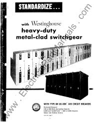
PURPOSE<br />
The purpose of this instruction book is to give the reader the<br />
maximum of useful information and suggestions concerning con<br />
struction, installation. operation and maintenance of \Vestinghouse<br />
Type RX-I Photo-Troller.<br />
The material contained herein has been assembled with a view<br />
toward facilitating installation and operation of the equipment<br />
and this book is intended to serve as a guide to installation and<br />
operating personnel so that the maximum useful life of the apparatus<br />
can be obtained .<br />
<strong>www</strong> . <strong>ElectricalPartManuals</strong> . <strong>com</strong>
COMMUNICATIONS<br />
When <strong>com</strong>municating regarding a product cov<br />
ered by this Instruction Book, replies will be greatly<br />
facilitated by citing COMPLETE NAME PLATE<br />
READINGS of the involved products. Also, should<br />
particular information be desired, please be very<br />
careful to clearly and fully STATE THE PROB<br />
LEMS AND ATTENDANT CONDITIONS.<br />
2<br />
<strong>www</strong> . <strong>ElectricalPartManuals</strong> . <strong>com</strong>
Type RX-l Photo-Troller<br />
Instructions for Installation<br />
FIG. I-THE RX-l PHOTO-TROLLER<br />
Westinghouse Electric & Manufacturing Company<br />
East Pittsburgh, Pa.<br />
3<br />
I.B. 5670-44-A<br />
<strong>www</strong> . <strong>ElectricalPartManuals</strong> . <strong>com</strong>
DESCRIPTION<br />
INDEX<br />
PREFACE . ......................... .<br />
LIST OF APPLICATIONS . . . . . . . . . . . . . . . . . . . . . . . . . . . . . . . . . . . . . . . . .<br />
Counting . ........................ ....... , . . , . ' ... . .. . . . '<br />
GENERAL DATA . ....................... , .. . . . . . . . . . . . . ..... .<br />
HOW TO SELECT AND APPLY PHOTO-TROLLERS . . ...... .... .<br />
Phototube Housings . ....... ..................... , ' , . . . . . . .<br />
PRINCIPLE OF OPERATION . ......................... , . .. . . .<br />
The Phototube-Amplifier Circuit . ................ , . .. ' .<br />
The Thyratron Control Circuit . ..... , , . , . . , . . , " . .. . , . .<br />
. . . .<br />
INSTALLATION ......... " . . . . . . . . . .. . .. . . .. . . .. . . . . . . . . .. . . . . .<br />
Mounting . .................... .<br />
Temperature Limits . . . . . . . .. . . , . . . . . . ... . . . .. . .. . ... . .. . . . . .<br />
A-C Voltage Variations . .... .. " . . .. . .. . ' . . .. . . . . . . . . . . , . .. .<br />
External Connections . , . . . .. . . . , . ..... . . , . . , , . . , . . . ..... , . . . .<br />
Operation , .. , . . . .. . . .. , . . , . . ' ... . . ' ... . .. . .. , .. . ' . . . ' , . . . . . . .<br />
Relay Characteristics . .... , . . . . . . . . . . . . . . . . . . . . . . . . . . . .<br />
Page<br />
Sensitivity . ......... , . . . . . .... . . . ... . . .. . . . .... . ... . . . . .. . . . . . 9<br />
Adjustments . . .................. , . . . " . . .. . . .. . , ' . . . . . . . . .<br />
WHAN TO DO IF PHOTO-TROLLER DOES NOT OPERATE<br />
SATISFACTORILy . ..... , . . . , . . .. . . . .. . . . . . .. . . . . , . . " . .. . . . .<br />
General Tests . ................................. ' , . . , . . . .<br />
Special Tests , .. ' . . . . ' , . . . , . . ' . ' . . . . . ' . ' .. . . . . , . . .. , . .. . , . . , . .<br />
Spare Tubes . ... ' . , . . . . . ' . ' . . . .. . .. . . . , . , . .. , . . . .. . . .. , , . . . . , .<br />
RENEWAL PARTS . , ... " . .. . . . .... . .. . . .<br />
" . . . , . ... . ...... . .. . , ..<br />
LIST OF ILLUSTRATIONS<br />
o.<br />
D<br />
5<br />
5<br />
5<br />
G<br />
6<br />
7<br />
7<br />
8<br />
8<br />
8<br />
8<br />
8<br />
n<br />
9<br />
9<br />
10<br />
10<br />
10<br />
10<br />
12<br />
12<br />
Page<br />
Fig. o.<br />
1 Type RX-l Photo-Troller . . . ... . . . . . , . . . . . . . . . . . . . . , . , . . 3<br />
2 Curve showing how much the phototube illumination must be<br />
decreased for various values of a-c. line voltage variation . .. , . . , . . . ()<br />
:3 Diagram of connections . .. . . . , .. , . , ........ , ........ , , . . . .. .. 7<br />
4 Thyratron tube operating characteristics . . , ........... , ...... , . . 8<br />
5 Curves showing dial position as a function of phototube illumination n<br />
6 Outline drawing for 60 cycle , . , . . , , , . ' , , , . , , .... , . . . . . . . . . . . . .. 11<br />
7 Outline drawing for 25 cycle . . .. . . . .. . . . . . . . . . .. . . . " ......... 11<br />
4<br />
<strong>www</strong> . <strong>ElectricalPartManuals</strong> . <strong>com</strong><br />
<br />
.."
(1)<br />
-westinghouse<br />
Type RX-l Photo-Troller<br />
PREFACE<br />
The RX-l photo-troller is one type of a line of<br />
general purpose photo-electric relays operated by<br />
an increase or decrease in the amount of light falling<br />
on a phototube. They are arranged to initiate<br />
an electrical scquency in response to changes of<br />
illumination caused by partially or <strong>com</strong>pletely<br />
interrupting a light heam. A few installations are<br />
shown which are representative of the great<br />
variety of applications.<br />
In order that maximum flexibility of application<br />
may be obtained, various types of light sources and<br />
phototube housings may be used as shown in<br />
attached Price Lists 1831O. Several types of<br />
photo-trollers are available, each of which is best<br />
adapted for particular applications.<br />
LIST OF APPLICATIONS<br />
Limit or "flag" switch where a mechanical switch<br />
is undesirable such as for<br />
Paper mills break indicator<br />
Automatic weighing<br />
Sheet catcher in steel mill<br />
Oscillating grinder belt<br />
Paper and cellophane bag machines<br />
Registering wrapper trademark on packaging<br />
machines<br />
Stopping mechanical devices at accurate position<br />
Liquid level control<br />
Initiating flying shear<br />
Door opening.<br />
Counting<br />
Parts on production lines such as crankshafts,<br />
boxes, tin sheets<br />
People entering or leaving buildings<br />
Automobile traffic.<br />
GENERAL DATA<br />
The RX-l photo-troIler is arranged with a steel<br />
panel which is hinged at the bottom of the case<br />
and held in place by one screw at the top. The<br />
indoor units are provided with a rectangular knockout<br />
in the door which may be removed to serve as a<br />
light aperturt' if the phototube is mounted in the<br />
cabinet.<br />
Instructions for Installation<br />
5<br />
A type SG relay is operated directly from the<br />
tube circuit. Thus, no interposing sensitive relays.<br />
such as are usually needed if radio amplifiers are<br />
used, are required. This relay has two pairs of<br />
contacts which can be arranged to give two normally<br />
closed contacts or one normally open and<br />
one normally closed contact.<br />
The RX-l photo-troller provides the power supply<br />
for a light source with either a 68 volts, ;j2<br />
candlepower lamp or a 6 volt. 5 ampere lamp.<br />
Style 849085.<br />
A terminal board is provided at the rear of the<br />
panel for all connections except to the relay contacts<br />
which are on the relay itself in front of the<br />
panel. The terminal board is readily accessible for<br />
installation, since the removal of a single screw<br />
permits swinging the panel down on hinges to hang<br />
from the bottom of the cabinet.<br />
The type RX-l is equipped with a phototube,<br />
an amplifier tube and a thyratron tube. The output<br />
of the WL-735 phototube is amplified by a 5i<br />
tube. This output, in turn, operates a \V L-B29<br />
thyratron which energizes the SG relay.<br />
A switch is provided so that the unit may be<br />
used to energize the SG relay, when light on the<br />
phototube is either increased or decreased. For<br />
either arrangement, a minimum of 1.0 foot-candle<br />
light intensity is required to operate the relay. The<br />
light intensity must be reduced at least 50% to<br />
insure positive operation of the relay.<br />
At least 0.2 second should be allowed between<br />
centers of light impulses, corresponding to 300<br />
operations per minute. At this speed of operation,<br />
the 0.2 second must be di vided equally between the<br />
"on" and "off" period. The maximum re<strong>com</strong>mended<br />
rate of operation is 150 per minute. However.<br />
the approximate time of light change required<br />
to operate the relay is 0.05 second.<br />
If the phototube is mounted in a separate housing,<br />
it may he located up to 25 cable feet distance,<br />
although standard housings are furnished with<br />
10 feet of cable, which is usually sufficient. Distances<br />
beyond 10 feet slow down the speed of<br />
response 25%, and longer times than those given<br />
for operation must be allowed . The footcandle<br />
rating of the unit is then also increased to 1.5<br />
footcandles.<br />
<strong>www</strong> . <strong>ElectricalPartManuals</strong> . <strong>com</strong>
(2) HOW TO SELECT AND APPLY<br />
PHOTO-TROLLERS<br />
The first fundamental in application of phototrollers<br />
is that it is desirable to have as much excess<br />
illumination as possible beyond ' that required by<br />
the rating, in order that the safety factor will be<br />
increased .<br />
Photo-trollers operate by variation of the quantity<br />
of light falling on the phototube. Ratings are<br />
given in terms of light intensity for greater convenience<br />
in application, and these ratings in terms<br />
of light intensity are based on the assumption that<br />
the full phototube or lens opening of the phototroller<br />
will be used, Therefore, if the photo-troller<br />
is used in such a manner that only a portion of the<br />
phototube or lens opening is open, proportionately<br />
greater light intensity must be allowed.<br />
If photo-electric equipment is to be operated in<br />
the vicinity of smoke, fog, dirt, steam or other<br />
similar conditions, it is necessary to add the best<br />
possible estimate of light loss factor so that adequate<br />
safety margin will be insured.<br />
Since photo-trollers operate by variation of the<br />
quantity of light falling on the phototube, it follows<br />
that the method of obtaining this variation is important.<br />
Two methods of varying illumination are<br />
in general use - variation of transmission and<br />
variation of reflection.<br />
Transmission is varied by arranging an opaq ue,<br />
or partially opaque, object to intercept the beam of<br />
light which normally passes from light source to<br />
.,<br />
'.c--i- --r-r- -,::r..-f-<br />
Westingho1tse Type RX-J Photo- Troller<br />
!1ax/mlJ.i'1'1<br />
""'-Fo ot Candle<br />
--'i--:r- --r., 111«?Minaoon<br />
100/0<br />
\<br />
2% Lme Voltage<br />
FIG. 2-CURVE SHO,\VING Hov .. ' Muca THE PHOTOTUBE ILLUM INATION<br />
MUST BE DECREASED FOR VARIOUS VALUES OF A-C, LINE VOL7AGE<br />
VARIATION<br />
6<br />
phototube. This is the most <strong>com</strong>mon method of<br />
operation and may be used for automobiles, people,<br />
paper sheets, steel sheets, packages, etc. Clear<br />
cellophane is obviously not very opaque and, therefore,<br />
does not vary the light beam much when<br />
intercepted by it. When operating with material<br />
of this nature whose opacity is not high, it is very<br />
important to know what this opacity is. Such<br />
applications are usually more difficult and it is<br />
re<strong>com</strong>mended that they be referred to the nearest<br />
District Office of the Westinghouse Company for<br />
re<strong>com</strong>mendations.<br />
Reflection is varied by arranging the optical<br />
system so that the light beam is reflected from the<br />
material to the photo-tube and the extent of this<br />
reflection is varied by the character of the surface<br />
of the material.<br />
The actual procedure to be used in selecting the<br />
proper photo-trollers and light source is:<br />
(1) Determine what portion of the light beam<br />
will be available under maximum illumination<br />
conditions.<br />
(2) Determine what portion of the illumination<br />
will be intercepted by the controlling obj ect.<br />
(3) Select a photo-troller having the general<br />
characteristics desired, and then<br />
(4) Select a <strong>com</strong>bination of photo-troller and<br />
light source such that at the distances and operating<br />
conditions determined under paragraphs (1)<br />
and (2) , adequate sensitivity will be obtained,<br />
(5) Re-check all variable factors to make certain<br />
that adequate safety margin is proceeded in the<br />
selection.<br />
(3) Phototube Housins<br />
The RX-1 photo-troller is arranged so that the<br />
phototube may be mounted inside the case. When<br />
this is done the knock-out in the case door should<br />
be pressed out to permit the light to reach the<br />
phototube. In many applications it is preferable to<br />
mount the phototube in a separate housing, and<br />
for this purpose, one of the housings shown in<br />
attached Price List 18-310 should be used.<br />
(4) Various types of light sources are shown in<br />
attached Price List 18-310, all of which , except the<br />
type L, can be used with the type RX-1 phototroller.<br />
In selecting the light source care must be<br />
taken that the minimum illumination on the<br />
phototube must not exceed the values given in<br />
Fig. 2.<br />
In this figure are shown different scales for the<br />
maximum illumination for different percentage<br />
changes in a-c line voltage. Using, for example, the<br />
<strong>www</strong> . <strong>ElectricalPartManuals</strong> . <strong>com</strong>
as«:: 2 per cent curve, it is seen that if the maximuti<br />
illumination is 3 foot candles, the minimum<br />
illumination must not exceed 1.9 foot candles.<br />
If, h,..'qwever, the maximum line voltage variation is<br />
20 p! cent and the maximum illumination is 3 foot<br />
candles at maximum a-c voltage, then the minimum<br />
illumination 0.9 foot candles is found by following<br />
the circle from A to B, then to C and to D. By<br />
using the curves in Fig. 2 in <strong>com</strong>bination with the<br />
light source curves in Fig. 7 of Price List 18-310,<br />
the required percentage reduction in illumination<br />
can be determined.<br />
Example : Light Source : Type F<br />
Voltage Variations : 10%<br />
Operating Distance : 30 feet<br />
From Fig. 7: Price List 18-3 lO is found, 2 footcandles.<br />
From Fig. 2: 2footcandies at 1O per cent voltage<br />
gives 0.8 footcandles. Minimum<br />
illumination.<br />
Consequently : The illumination must be decreased<br />
from 2 footcandles to 0.8<br />
footcandles, or 60 percent.<br />
PANEL (REAR VIEW)<br />
c<br />
G<br />
TRANS.<br />
Westinghouse Type RX-J Photo- Troller<br />
wIRE<br />
NO<br />
WIRING TABLE<br />
COLOR<br />
(5) PRINCIPLE OF OPERATION<br />
The RX-1 photo-troller as shown in Fig. 3 consists<br />
essentially of two different control circuits,<br />
namely the phototube-amplifier circuit and the<br />
Thyratron control circuit.<br />
The PhototubeAmp1ifier Circuit<br />
The purpose of this circuit is merely to amplify<br />
the variations in voltage caused by changing illumination<br />
on the phototube. The circuit consists of<br />
a d-c source supplied by the recto x rectifier connected<br />
between 16 and 17. A voltage divider, consisting<br />
of a 5000 ohm potentiometer and two 25000<br />
ohm resistors, is connected across this d-c source.<br />
The phototube circuit consists of the WL-735<br />
phototube connected between A and C and the 10<br />
MEGOHM resistor C-16. If the illumination on<br />
the phototube is increased, an increasing amount<br />
of current flows through the tube, thus making<br />
Lead C more positive relative to the potentiometer<br />
tap G. The voltage between C and G is the grid<br />
control voltage for the 57 amplifier tube. This tube,<br />
which is of the screen grid type consists of a heater<br />
connected to 13-14, a cathode connected to G, a<br />
screen grid connected to A, a control grid connected<br />
to C and an anode connected to 15.<br />
WIRE<br />
NO<br />
COLOR<br />
I REO ' 13 BROW c::::- N<br />
-::-:--:= -- ;<br />
2 BLACK' REO TR ,14 BLACK-BLUE<br />
3 RED- BLACK 15 COPPER WIRE<br />
I 4 BLACK 16 COPPER WIRE<br />
-- -_-<<br />
5 BLUE 17 COPPER WIRE<br />
6 BLUE 18 PIG T,"'AI"'L'-<br />
7 YElLOW- RED TR. 1 9 PIG TAI L<br />
B BROWN·GREENTR. 20 RED<br />
9 YELLOW<br />
,10 BLUE-YE LLOW<br />
II GREEN A REO<br />
12 BlACK:YEllOW TR C+BLO=A-=C""K-- -- ;<br />
1\ lTO<br />
BE USED<br />
OVER<br />
SHIELDED<br />
I<br />
CABLE •<br />
AS SHOWN '<br />
i L_ EXTERNAL CONNECTIONS<br />
20 '<br />
17<br />
<br />
18 ..J<br />
RI M HER<br />
TO PA STE IN I 025 MEG<br />
CAB""<br />
J<br />
FIG. 3-DIAGRA,r OF CONNECTIONS<br />
7<br />
, I<br />
III ______<br />
SCHEMATIC<br />
t2 24<br />
RELAY ,<br />
_ _______ ----'<br />
} 220/440<br />
220/440<br />
...J<br />
, LINE<br />
! VOLTS<br />
<strong>www</strong> . <strong>ElectricalPartManuals</strong> . <strong>com</strong><br />
115<br />
230<br />
220<br />
440
Vote ' EA Scale /5<br />
-- o of other<br />
Scales<br />
rime<br />
IFestinghouse Type RX-l Photo- Troller<br />
Voltage<br />
8-18<br />
EA '" Anode Vo/ta. 9"e<br />
8-20<br />
FIC, 4 -TllYR.\TRO'S TPBE OPER;\ TlNG CHARAC rERIS ncs<br />
The characteristics of the 57 tuhe are such that<br />
the tube will pass no current if the voltage between<br />
C and G is more negative than approximately 2<br />
vol ts. If the grid voltage is made less negative the<br />
current through the tube will increase and will<br />
reach its maximum value when the grid voltage<br />
is approximately zero.<br />
When the current through the 57 tube is zero the<br />
potential of 15 is positive in relation to the poten<br />
tial of A. As the 57 current is increased the potential<br />
difference between 15 and A is decreased to zero<br />
and then again increased so that the potential of<br />
15 be<strong>com</strong>es negative relative to the potential of A.<br />
From the preceding discussion it may be seen<br />
that when the illumination on the phototube is<br />
low the poten tial of 15 is positive relative to A,<br />
whereas with the phototube highly illuminated the<br />
potential of 15 is negative relative to A.<br />
The Thyratron Control Circuit<br />
The WL-62) Thyratron tube consists of a heater<br />
connected to 810, a cathode connected to 8, an<br />
anode connected to 20 and a control grid connected<br />
to the 0.25 MEG resistor connecting to lead 19.<br />
The anode is connected in series with the SG relay<br />
coil to lead 7, and the cathode is connected to lead<br />
8_ When the tube be<strong>com</strong>es ionized the resistance<br />
of the tube between 20 and 8 changes from an<br />
infinite value to a low value, and rectified a-c<br />
current flows from 7 through the relay coil to 20,<br />
through the tube and to 8. The voltage between the<br />
grid and the cathode determines whether the tube<br />
conducts current or not.<br />
If this voltage is more negative than approxi<br />
mately 6 volts, the tube does not be<strong>com</strong>e ionized,<br />
no current flows, and the SG relay is deenergized.<br />
If the grid voltage is made more positive, the tube<br />
conducts current and the relay is closed.<br />
The control voltage for the vVL-629 is a <strong>com</strong><br />
bination of a 135 degree phase shifted a-c voltage<br />
<strong>com</strong>ponent obtained from capacitor 8-18, and a<br />
8<br />
d-c <strong>com</strong>ponent obtained from the amplifier tube<br />
circuit 15-A, and which is applied to the grid<br />
circuit 18 19 by means of the double pole re<br />
versing switch.<br />
The control voltage characteristics for the<br />
WL-629 tube are shown in Fig. --1 in which<br />
represents th e critical grid voltage needed. It will<br />
be seen that when voltage 1819 is made more<br />
positive the \VIAI29 tube breaks down at A at the<br />
beginning of the a-c voltage wave , and conducts<br />
current during the remainder of the half cycle.<br />
The purpose of the reversing swi tch is to reverse<br />
the operation of the relay relative to the change of<br />
phototube illumination. Wi th the switch in the<br />
"UP" position the relay is closed when the photo<br />
tube is illuminated. With the switch in the "down"<br />
position the relay is energized when the phototube<br />
is dark.<br />
(6) Mounting<br />
INSTALLATION<br />
Mount the photo-troller with the panel in a<br />
vertical position. If the phototube is to be mounted<br />
inside the photo-troller case, remove the knockout<br />
in the case door to permit light to reach the photo<br />
tube. If the phototube is mounted in a separate<br />
housing, the housing may be mounted in any con<br />
venient position, up to 10 feet distant from the<br />
photo-troller, or 25 feet if the photo-troller is<br />
derated as outlined in paragraph l.<br />
The light source may be mounted in any position<br />
except that the lamp base must not be higher than<br />
the lamp filament.<br />
(7) Temperature Limits<br />
The photo-troller should be mounted in a loca<br />
tion where the ambient air temperature does not<br />
exceed llO°F. If the photo-troller is mounted near<br />
furnaces or other equipment radiating an excessive<br />
amount of heat , the photo-troller should be shielded<br />
by means of a suitable shield. The maximum air<br />
temperature at the location of the phototube hous<br />
ing should not exceed 150°F.<br />
(8) A-C Voltage Variations<br />
The a-c supply voltage should be within ± 10<br />
per cent of rated voltage. If the a-c voltage varies<br />
more than 2 per cent. total, the conditions out<br />
lined in paragraph 4 should be considered .<br />
<strong>www</strong> . <strong>ElectricalPartManuals</strong> . <strong>com</strong><br />
-
(9) External Connections<br />
Connect the photo-troller as shown in Fig. 3,<br />
making sure that connections to terminals 1 to 4<br />
are made as shown in the table in this figure.<br />
Connect the light source to terminals 5-6, using<br />
cahle with 80 amperes capacity. When an extended<br />
photo-tube is used , do not place the phototube<br />
in the socket inside the case, but connect the<br />
phototube housing to terminals A-C by means of<br />
cahle PDS-7415-2 as supplied with the phototube<br />
housing. Make sure that terminal A on the phototroller<br />
terminal board is connected to terminal A in<br />
the phototube housing.<br />
Run the cable in grounded metallic conduit.<br />
with no other leads in this conduit. The length of<br />
the phototube cable must not exceed 10 feet unless<br />
the photo-troller is derated as outlined in paragraph<br />
1, in which case cahle up to 25 feet long may<br />
he used . Do not splice the phototube cable, and<br />
use no friction tape or other types of tape at the<br />
ends of the cable.<br />
Ground terminal G inside the photo-troller case<br />
to a waterpipe.<br />
Run leads connecting to the rclay contacts directly<br />
to the knockouts on the left hand side of the<br />
photo-troller case. Do not run relay leads across<br />
the photo-troller either in front or in rear.<br />
(ll) Operation<br />
With the switch in up position the relay is<br />
closed when the phototube is illuminated. \\7ith<br />
the switch in the "down" position, the relay IS<br />
closed when the phototube is dark.<br />
(10) Relay Characteristics<br />
Contact Interrupting Capacity<br />
H'estingholtJe Type RX-J Photo-Troller<br />
One "lVlake" . ........ 20 12<br />
One "Break" . .......... 10 6<br />
*Two "lV1ake" in series . . 30 20<br />
*Reverse left hand stationary co ntact.<br />
Note : Two "Break" Contacts cannot be used.<br />
Contact Carrying Capacity<br />
One "make" contact: 12 amp. continuous.<br />
One "break" contact : 6 amp. continuous.<br />
Operations per Minute<br />
100<br />
80<br />
'"<br />
. 60<br />
:'\!<br />
"<br />
<br />
-... 40<br />
.
(13) Adjustments :<br />
(1) Turn on power and allow unit to warm up<br />
5 minutes.<br />
(2) Focus light source.<br />
(3) With phototube entirely dark turn potentiometer<br />
until relay operates. The dial position<br />
should now be approximately 70.<br />
(4) With maximum a-c supply voltage and<br />
minimum illumination on the phototube adjust the<br />
dial until the relay operates. Observe dial position<br />
D max. If necessary reduce the illumination by<br />
throwing the light beam out of focus so that D max.<br />
is not less than 40. With minimum a-c supply voltage<br />
and maximum illumination on the photo tube<br />
cut off . of the light by means of an opaque<br />
object in front of the phototube, and adjust the<br />
dial until the relay operates. Read the dial position<br />
D min. To assure reliable operation, D minimum<br />
should be at least 1.5 divisions less than D maximum.<br />
If 15 divisions are not obtained the intensitv<br />
of illumination must be increased by moving tile<br />
light source nearer the phototube, or the difference<br />
between maximum and minimum illumination<br />
must be increased. If, with one-half of maximum<br />
illumination, it is not possible to obtain relay<br />
operation, it is re<strong>com</strong>mended that the illumination<br />
be decreased until the relay operates with the dial<br />
at the 0 position.<br />
WHAT TO DO IF THE PHOTO-TROLLER<br />
DOES NOT OPERATE SATISI
"<br />
4 ..i. 16 1 ,<br />
I<br />
Westinghouse Ty}')e RX-J Photo-Troller<br />
2 Knockouts (Tall a Bottom)<br />
/ Locoled as Shown<br />
L I I-.J<br />
t 22<br />
2 '2 t<br />
2 Knockouts (Top 8 Bottom)<br />
Localed as Shown<br />
4 Holes for<br />
t" Mtc). Bol18<br />
F!G. 6-Ol:rL1:"H': DR.\.WING FOR 60 CYCLE<br />
FIG. 7-0UTLI"E DRAW'''G FOR 25 CYCLE<br />
11<br />
<strong>www</strong> . <strong>ElectricalPartManuals</strong> . <strong>com</strong><br />
4<br />
2<br />
lo lL<br />
8
Westinghouse Type RX-l Photo-Troller<br />
(16) Spare Tubes<br />
1 Phototube WL-735.<br />
1 RCA-57 Amplifier Tube.<br />
1 - \V T Aj29 Thvratron Tube.<br />
<strong>www</strong> . <strong>ElectricalPartManuals</strong> . <strong>com</strong><br />
,<br />
1
\,.,.,<br />
;"" .<br />
Supersedes all previous issues of Price List 18-310 and<br />
Price Supplement 18-310; Price List 18-315 and Price Supplement 18-31 5;<br />
Price List 18-316 and Price Supplement 18-316. PRICE LIST 18-310<br />
EFFECTIVE MARCH 20, 1942<br />
WESTI""GHOUSE INDUSTRIAL MOTORS AND CO""TROLLERS<br />
PHOTO.TROLLERS, PHOTOTUBE HOUSINGS<br />
AND LIGHT SOURCES<br />
(See Descriptive Data 18-310) (For Other Photo-Trollers See Price List 18-312)<br />
SELECTION OF EQUIPMENT<br />
Before re<strong>com</strong>mending equipment for any application, the customer's problem should be thoroughly understood and<br />
the following information should be obtained:<br />
1. Distance between light source and phototube,<br />
2, Interruption of 50% of light beam, based on a 1%;" diameter beam, necessary for maximum operating distance.<br />
3, Operating conditions such as temperature, dust and weather conditions (indoor or outdoor),<br />
4<br />
S d f ' { a. Number of operations per minute.<br />
• L pee 0 opera tIon. b. Time of single operation.<br />
5, Space available for mounting the light source, phototube housing and/or Photo-Troller.<br />
Having obtained above information, consult the charts below to select the proper equipment. For register regulator applications<br />
see Pr:cG Lists 18-311 and 18-5 13.<br />
TYPE F<br />
General<br />
Purpose<br />
to operate<br />
from<br />
Phol'O<br />
troUer', or<br />
5,5 volts<br />
o.<br />
TYPE 0<br />
voltagO<br />
General<br />
Purpose<br />
to operate<br />
from<br />
supply,<br />
115 volts<br />
TYPE L<br />
Pulsating<br />
light<br />
LIGHT<br />
SOURCES<br />
TYPE E<br />
TYPE L<br />
_ =-<br />
;;::<br />
eA ""g:j<br />
FOR INDOOR USE ONLY<br />
WHEN PHOTOTUBE HOUSING IS REQUIRED<br />
POO',',bo HOO'::::::::::,,:::: , : H , ,,tog fu,<br />
'HDTO..<br />
OVER 20' AND UP TO 40'<br />
:::::. - -- - ----- - ----r-<br />
<br />
---------<br />
_ _ "t' _ _<br />
OVER 20' AND UP TO 40'<br />
UP TO :W<br />
(Wlren .po .. I. no,
18-310 PRICE LIST<br />
PAGE 2 WESTINGHOUSE INDUSTRIAL MOTORS AND CONTROLLERS<br />
PHOTO-TROLLERS, PHOTOTUBE HOUSINGS AND LIGHT SOURCES-Continued<br />
Type Description<br />
Style<br />
Including<br />
Tubes<br />
RX Indoor<br />
*RX-I Indoor<br />
I<br />
PHOTO-TROLLERS<br />
POWER St;PPLY TUBES IcLuDED<br />
Volt:; Cycle; 0l'umber Type Description<br />
1 083 311<br />
1 083 312<br />
1 083 313<br />
115/230<br />
220/440<br />
115/230<br />
50/60<br />
50/60<br />
25<br />
1<br />
1<br />
WL-735<br />
WL-6Z9<br />
Phototube<br />
Thyratron<br />
$ 58<br />
58<br />
66<br />
1 083 314 220/440 25 6()<br />
1 083 315<br />
1 083 316<br />
115/230<br />
220/440<br />
50/60<br />
50/60<br />
1<br />
1<br />
WL-735<br />
WL-629<br />
Phototube<br />
Thyratron<br />
78<br />
78<br />
1 083 317<br />
1 083 ,3 18<br />
115/230<br />
220/440<br />
25<br />
25<br />
1 '57 Amplifier 80<br />
80<br />
1 WL-735 Phototube<br />
RX-2 Indoor 1 083 319 115/230 30/60 1 WL-629 Thyratron 108<br />
1 083 320 220/440 50/60 1 '57 Amplifier 108<br />
RX-2 Outdoor 1 083 321 115/230 50/60<br />
1<br />
1<br />
WL-735<br />
WL-629<br />
Phototube<br />
Thyratron<br />
HiS<br />
165<br />
1 083 322 220/440 50/60 1 '57 Amplifier<br />
RX·3 Outdoor<br />
Indoor<br />
RXT Time Delay<br />
1-5 Seconds<br />
*RR·5<br />
1 224 834 115/230 50/60 119<br />
1 224 835 220/440 50/60 1 WL-i35 Phototube 119<br />
1 227 682 115/230 25 1 WL-629 Thyratron 125<br />
1 227 966 220/440 25 125<br />
1 083 323 115/230 50/60 91<br />
1 083 324 220/440 50/60 1 WL-735 Phototube 97<br />
1 083 325 115/230 25 2 WL·629 Thyratron 99<br />
1 083 326 220/440 25 99<br />
1 WL-735 Phototube<br />
Indoor 966 579 115/230 5·/60 1 RJ-571 Amplifier 192<br />
Hi-Speed 1 032 195 115/230 25 1 KU-627 Thyratron 2112<br />
.. See Price List 18-513, for Register Regulator Applications,<br />
I<br />
LIGHT SOURCES<br />
Style POWER SUPPLY Shipping PRICE<br />
Type Description Incl,<br />
---<br />
Weight, Incl,<br />
Lamp<br />
Lbg, Lamp<br />
Volts<br />
Cycles<br />
Watts<br />
D General Purpose, with transformer, 829 396<br />
D indoor, visible light only 829 397<br />
E High intensity. with transformer. 849 186<br />
E Indoor, or outdoor, visible hght 849 187<br />
L Long range with motor driven in- 1 083 460<br />
L terrupter, indoor or outdoor 1 083 461<br />
. . Infra red filter for types E and L<br />
only. 10% transmission. 1 033 919<br />
. .<br />
Infra red filter for types E and L<br />
only. 20% transmission. 1 083 482<br />
F General purpose. indoor, visible<br />
For operation from<br />
to-'!f;;ller.<br />
Type I<br />
A<br />
Description<br />
General Purpose. with 10<br />
foot leads, Indoor only.<br />
B Splash-Proof with 10 foot<br />
leads. I ndDor only.<br />
ORDERING INSTRUCTIONS<br />
When the proper Photo-Troller has<br />
been selected, specify the following<br />
when ordering : (1) style, (2) type, (3)<br />
description, (4) voltage, (5) frequencycycles.<br />
The accessory light source and phototube<br />
housing should be entered as separate<br />
items,<br />
PHOTOTUBE HOUSINGS<br />
U5/230<br />
220/440<br />
115/230<br />
220/440<br />
115/230<br />
220/440<br />
. "<br />
. "<br />
, "<br />
" .<br />
25-60<br />
25-60<br />
25-60<br />
25-60<br />
5(}-60<br />
5!Hi0<br />
. - . -<br />
. - . .<br />
21 11 $21.511<br />
21 11 21 . 511<br />
35 18 27,00<br />
35 18 27.00<br />
65 30 92 ,00<br />
65 30 92 ,110<br />
. . 1 10.00<br />
" 1 10 .00<br />
831 706 5.5 a.-c. or dc. 18 4 15,00<br />
Style Shipping PRICE<br />
Without Weight, Not Incl.<br />
Tubes Lbs, Tubes<br />
I 073 380 5 $12<br />
1 073 382 5 14<br />
Spare tubes<br />
TUBES<br />
should be ordered as<br />
separate items on the order. Tube prices<br />
are found in Price Li::ts 86-520 and<br />
86-530, Renewal tubes for equipment<br />
in operation should be ordered direct<br />
from the Special Products Sales Department,<br />
Bloomfield Vlorks.<br />
Return of tubes for any reason should<br />
be made in accordance with Selling<br />
Instructions 86-500,<br />
Prices are subject to chang£' without notice.<br />
PRICES<br />
Photo-Troller prices include all necessary<br />
tubes,<br />
Light source prices include the lamp .<br />
Phototube housing prices do not include<br />
phototube,<br />
No reductions are made for the omission<br />
of cabinets on Photo-Trollers,<br />
Semi-dust-tight cabinets may be order<br />
ed for all Photo-Trollers except the type<br />
RX-2 outdoor modeL Add $3 to price<br />
listed above,<br />
iVhen leads longer than the standard<br />
10 feet furnished with phototube hous<br />
ings are desired specify required length<br />
of PDS 7415-2 cable as a separate item<br />
on order. Cable $. 15 per foot, W-2 fOI<br />
length over 10 feet,<br />
<strong>www</strong> . <strong>ElectricalPartManuals</strong> . <strong>com</strong>
..<br />
WESTINGHOUSE INDUSTRIAL MOTORS AND CONTROLLERS PAGE 3<br />
PHOTO-TROLLERS, PHOTOTUBE HOUSINGS AND LIGHT SOURCES-Continued<br />
APPLICATION INFORMATION ON GENERAL PURPOSE PHOTO-TROLLERS<br />
AND ACCESSORIES-FOR TRANSMITTED LIGHT<br />
DESCRIPTION OF TYPES The RR-5 is intended primarily for<br />
operation from the current received from<br />
Type RX a phototube. In addition, it may be<br />
For general purpose indoor, industrial operated by contacts and variable resist<br />
application where the change in light on ances or voltages in special applications.<br />
the phototube is more than 50% and It is particularly applicable if the light<br />
where less than 150 operations per change is of too short duration to actuate<br />
minute with equal "off"-"on" periods a magnetic relay coil using ordinary<br />
are required. 18-310 Photo-Trollers.<br />
Type RX-l<br />
For the same applications as the type<br />
RX above except where greater distances<br />
(up to 40 feet maximum) must be<br />
covered.<br />
Type RX-2<br />
APPLICATIONS<br />
"Photo-Troller" is the Westinghouse<br />
trade name for a photo-electric relay.<br />
For operation, Photo-Trollers depend<br />
upon the interruption of a light beam<br />
falling upon a phototube. In industrial<br />
practice photo-electric control usually<br />
For indoor or outdoor installations consists of at least two units, namely:<br />
where distances greater than 50 feet a light source and a Photo-Troller. In<br />
and up to 225 feet must be spanned. this case the Photo-Troller must con<br />
Since it is built to operate on modulated<br />
tain the phototube. However if the<br />
light it must be used with the special<br />
Photo-Troller cannot be mounted at the<br />
type L light source which produces<br />
desired location because of size or<br />
modulated light.<br />
appearance, the phototube may be<br />
Type RX-3<br />
placed in a phototube housing and<br />
mounted away from the Photo-Troller<br />
This Photo-Troller 1S designed for as far as 10 feet. This distance is limit<br />
outdoor service at distances up to 30 ed by the speed required. The closer<br />
feet between the light source and photo- the phototube is placed to the Photo<br />
tube when used with the type E outdoor Troller the faster the relay can act<br />
light source.<br />
Type RX-T<br />
The Photo-Troller can be used to<br />
perform automatically many tasks which<br />
Were formerly performed by manually<br />
This Photo-Troller has a time delay operated relays. It should be remember<br />
which begins when light is removed ed that a Photo-Troller is primarily a<br />
from the phototube and is adjustable control device and therefore, is always<br />
from 1 to 5 seconds. The time delay is<br />
automatically reset any time light is<br />
again placed on the phototube.<br />
Type RR-5<br />
A special Photo-Troller to be used<br />
where high-speed action or "lock-in"<br />
operation is required. It can also be<br />
used for register regulator applications.<br />
See Price List 18-513.<br />
used in conjunction with other elec<br />
trical devices which perform the actual<br />
operation. Following is a brief list of<br />
uses for Photo-Trollers:<br />
1. As a limit switch or flag switch :<br />
(a) In paper or rubber mills to<br />
indicate a break in paper or<br />
rubber web.<br />
(b) For automatic weighing.<br />
17<br />
(c) For stopping mechanical de<br />
vices at accurate or limit posi<br />
tions.<br />
(d) For liquid level.<br />
2. As a safety device for :<br />
(a) Elevator doors.<br />
(b) Pulverized fuel furnaces.<br />
(c) Punch presses, bending and<br />
shearing machines.<br />
(d) Railroad crossings on industrial<br />
sidings.<br />
(e) Electric test floors.<br />
3. As controls for :<br />
(al Alarms indicating the ap<br />
proach of unauthorized persons<br />
to forbidden areas.<br />
(b) Alarms indicating the ap<br />
proach to dangerous areas in<br />
chemical plants, powder mills,<br />
etc. or areas in which overhead<br />
cranes are operating.<br />
4. For counting of :<br />
(al Parts on production lines such<br />
as boxes, tin or paper sheets,<br />
packages, and numerous other<br />
items.<br />
(b) People entering or leaving<br />
buildings.<br />
,(') AuwlIlubile traffic.<br />
5. Opening of doors to garages, public<br />
buildings and factories.<br />
6. Automatic drinking fountain con<br />
trol.<br />
7. Temperature limit indicators for<br />
hot metals.<br />
LITERATURE REFERENCE<br />
Instruction Instruction<br />
Type Book Lea!let<br />
2641<br />
RX 5670--43 2640<br />
RX-!<br />
RX-2 5670-45<br />
5670--44<br />
2646<br />
RX-3 5670-4.l 2640<br />
RX-T 5670--46 2647<br />
RR-5 5751<br />
<strong>www</strong> . <strong>ElectricalPartManuals</strong> . <strong>com</strong>
18-310 PRICE LIST<br />
PAGE 4 WESTINGHOUSE INDUSTRUL MOTORS AND CONTROLLERS<br />
PHOTO-TROLLERS, PHOTOTUBE HOUSINGS AND LIGHT SOURCES-Continued<br />
PHOTO-TROLLER CONTACTOR<br />
RATINGS<br />
Contacts<br />
Provided<br />
One<br />
Normally<br />
Open<br />
One<br />
Normally<br />
Closed<br />
t' 20.<br />
Amps.<br />
12.<br />
7.<br />
2.<br />
0.7<br />
r 10.<br />
t : 1.<br />
t(<br />
RATI"G PER<br />
COKTACT A-C.<br />
0.4<br />
Volts<br />
110 A-C.<br />
220 A-C.<br />
440 A-C.<br />
125 D-C.<br />
250 D-C.<br />
110 A-C.<br />
220 A-C.<br />
440 A-C.<br />
125 D-C.<br />
250 D-C.<br />
--<br />
-- -- -- -<br />
30.<br />
110 A-C.<br />
Two<br />
20.<br />
220 A-C.<br />
Normally<br />
Open in<br />
Series<br />
10.<br />
3.<br />
1,<br />
Max. Continuous<br />
Carrying Capacity<br />
440 A-C.<br />
125 D-C.<br />
250 D-C.<br />
Normally Open--1 2 Amps.<br />
Normally Closed--6 Amps.<br />
---- -----<br />
POWER CONSUMPTION, DIMENSIONS AND WEIGHTS<br />
Type<br />
RX<br />
Indoor<br />
RX-I<br />
lrodoor<br />
RX-2<br />
Indoor<br />
Outdoor<br />
RX-3<br />
RX-T<br />
RR-S<br />
APPROXIMATE<br />
POWER<br />
CONSUMPTIOK<br />
WATTS<br />
Without With<br />
Light Light<br />
Source Source<br />
18<br />
30 48<br />
3S S3<br />
3:i 53<br />
30 i 48<br />
3'- .' : 53<br />
100 I 125<br />
Width I<br />
ApPROXIMATE<br />
OVERALL<br />
DIMENSIONS<br />
IN INCHES<br />
60 CYCLES ONLY<br />
Height I Depth<br />
ApPROXIMATE<br />
SHIPPING<br />
WEIGHT,<br />
Lns.<br />
9 11 5 }4 22<br />
9 11 5)4 22<br />
9 11 SJ{ 22<br />
17 9Y:j 4S<br />
13<br />
I<br />
13 17 9Y:j 46<br />
9 I 11 S!4' 22<br />
15 I 20 12 60<br />
<strong>www</strong> . <strong>ElectricalPartManuals</strong> . <strong>com</strong>
Memorandum<br />
(Use Ink)<br />
<strong>www</strong> . <strong>ElectricalPartManuals</strong> . <strong>com</strong>
Memorandum<br />
(Use Ink)<br />
20<br />
<strong>www</strong> . <strong>ElectricalPartManuals</strong> . <strong>com</strong>
-.-<br />
. ... \<br />
0""<br />
II g..,.<br />
i<br />
: V-, :<br />
>1<br />
?: - - . ! · C . ' .<br />
, ! •<br />
f', :<br />
I .!<br />
I<br />
1.$$'23-.1408<br />
;:; ... 'tiNE 5,6,7, a 8<br />
'12 ! of<br />
• ;; li , 04<br />
"1' . i · :;;<br />
: I ! ill .<br />
"lj'l! J<br />
j I . . m<br />
.<br />
Z<br />
ii' ,. '. o :Z:<br />
... ., ,W , «4 0<br />
J '4;<br />
... '" .- ; II!<br />
•<br />
•<br />
Oft<br />
n<br />
...<br />
<br />
<br />
,tl ! ;,;<br />
-- · .... i! n<br />
I I iii I <br />
.. L._t' . Q<br />
" , !<br />
I<br />
';-. 1· ... '"<br />
1 ': c:<br />
I · !.. ."<br />
. CD j/ . I;; ' ,. iol<br />
, or- ()<br />
' N i 2:<br />
I ....<br />
I I<br />
fUll<br />
.. = :::!<br />
(-------. \<br />
\ \<br />
<br />
"<br />
'>,<br />
\<br />
\<br />
,<br />
.... ----1<br />
_<br />
. r71L<br />
/}r' .\ .<br />
It"'>"- "-"'"<br />
....<br />
J'"<br />
\ .... ..<br />
.l..<br />
i 'J')<br />
t--+--::=s- ---<br />
r . . ··- -·-- . . _.<br />
"'----4- . ' . -. ' .-r<br />
\,, __ .j<br />
\?/'<br />
·\..···_···YJ<br />
" \ ,., / ;". (' ;'<br />
0/"<br />
/<br />
,.<br />
- --_ ... _ - - -- - - .. _-- - - - -- - ... .... .- -- -. - --- - --- - -- -<br />
;l" RX- I PHOTOT ROLLER<br />
j.,<br />
I OTOX .<br />
'REAR VIEW ' .<br />
WIRING<br />
-- - - -_ .. - - "---'- - ---,<br />
• IOT i<br />
I<br />
TS -t! .J i •<br />
I ·<br />
I<br />
. .<br />
I I<br />
• ·<br />
I 1 I<br />
.<br />
• L.J; d('"IOTI! IIAKE IUK TIIIa<br />
'<br />
L - --- -= - - --2!!!<br />
RESISTOR a POT. TABLE<br />
NO. IIALUE IN OHMS STYLE NO.<br />
I R<br />
1000 1250332<br />
22000 1496899<br />
3 111 22000 1496899<br />
4R 10000000 1441 110<br />
S ill 220000 14968,.<br />
811/ 220000 1496888<br />
711/ 100000 1496t03<br />
220000 1498886<br />
1 " - 5000 1249080<br />
2R<br />
G ill<br />
- .1. ' _. ..•. __ L. _ _<br />
1039904<br />
10'39905<br />
i I:: I
W E S T I N G H O U S E<br />
TYPE SC -1 REGISTER REGULATOR<br />
FOR WINDER CONTROL<br />
INSTRUCTIONS FOR OPERATION<br />
INSTRUCTIN BOOK 5670-72<br />
1·· "9 )<br />
./ I<br />
WEST INGHOUSE ELECTRIC AND MANUFACTURING COMPANY<br />
EAST PITTSBURGH WORKS<br />
EAST PITTSBURGH, PA .<br />
<strong>www</strong> . <strong>ElectricalPartManuals</strong> . <strong>com</strong>
C\J<br />
!:'-<br />
I<br />
o<br />
!:'<br />
\.0<br />
l.I\<br />
CAUTION - - - - - - -<br />
LB. 5670-72<br />
INDEX TO CONTENTS<br />
I - DESCRIPTION - - - - - - - - - -<br />
2. Control Cabinet -<br />
3. Scanner - - - - - - - -<br />
. Push Button and Transfer Sw itch -<br />
5. Limit Sw itches - - -<br />
II - OPERAT ION- - - - - - - - - - -<br />
III - INSTALLATION - - - - - - - -<br />
10. Mounting of Cabinet - - - - - - -<br />
11. Mounting and Location of Scanner<br />
13 . Connections - - - - - - - - - - -<br />
IV - PLACING INTO SERVICE - - - - - - - - -<br />
1 . Preliminary Tests - - - - - - - - - -<br />
15 . Operation of Tubes - - - - - - - - - - - - -<br />
16 . Adjustment of Toggle Switch No. 1 - - - - - - - - - -<br />
17 . Connection of Motor Field Leads 5-6 - - - - -<br />
18 . Adjustment of Limit Switches - - - - - - - - - - - -<br />
19 . Manua l Push Buttons - - - - - - - - - - - - - - -<br />
20. Connections of Jumper 11 to Resistor Termina ls- -<br />
2. Reconnection for Light or Dark Operation- - - - - - -<br />
V - ARRANGEMENT OF PRINTING AND COLOR OF MATERIAL - - - - -<br />
22 . Arrangement of Print ing - - - - - - - - - - -<br />
23. Color of Ma terial - - - ' - - - - - - - - - - - - - - -<br />
VI - ROUTINE OPERATION - - - - - - - - - - - - - - - -<br />
2. Adjus tment of Potent iometer - - -<br />
25. Starting - - - - - - - - -<br />
-<br />
•<br />
- -<br />
-<br />
- - - - - - -<br />
26. Stopping - - - - - - -<br />
27. 10-Pole Transfer Switch - - -<br />
-<br />
-<br />
-<br />
-<br />
-<br />
-<br />
-<br />
-<br />
-<br />
- - -<br />
VII - TUBE TESTS - - - - - - - - - - - - - - - - -<br />
VII I - SPARE TUBES - - - - - - - - - - - - - - - - - -<br />
IX - SENSITIVITY OF CONTROL - - - - - - - -<br />
X - WHAT TO DO IF EQUIPMENT DOES NOT OPERATE PROPERLY -<br />
35 . Genera l Tests - - - - - - - - - - - - - - - - - - - -<br />
36A.D-C. Motor Does Not Operate - - - - - - - - - - -<br />
36B . Tube I Does Not Conduc t Current When Tube II<br />
Conduc ts Current - - - - - - - - - - - - - - - -<br />
36C . Tube IV Does Not Conduct Current When Tube II<br />
Does Not Conduc t Current - - - - - - - - -<br />
36D . Tube II Does Not Conduc t Current When Tube III<br />
Does Not Conduct Current - - -<br />
-<br />
-<br />
-<br />
-<br />
-<br />
-<br />
36E. Tube II Breaks Down Cont inua lly -<br />
36F . Tube III Does Not, Break Down<br />
36G • Re gula t ion is Un,s table - - - -<br />
- -<br />
-<br />
-<br />
-<br />
-<br />
-<br />
-<br />
-<br />
-<br />
-<br />
-<br />
-<br />
-<br />
-<br />
- -<br />
- -<br />
-<br />
-<br />
DRAWING 'LIST<br />
2-A-278 - Scanner Arrangement and Operating<br />
. Comb inations<br />
2-A-7813 - Wiring ,Diagram<br />
<strong>www</strong> . <strong>ElectricalPartManuals</strong> . <strong>com</strong><br />
2 .<br />
3<br />
<br />
<br />
q<br />
<br />
<br />
5<br />
6<br />
6<br />
6<br />
7<br />
8<br />
8<br />
8<br />
9<br />
9<br />
10<br />
10<br />
10<br />
10<br />
11<br />
11<br />
11<br />
'12<br />
12<br />
12<br />
12<br />
12<br />
13<br />
13<br />
lq<br />
16<br />
16<br />
16<br />
16<br />
16<br />
17<br />
17<br />
17<br />
17
C\J<br />
t--<br />
I<br />
o<br />
t-<br />
\0<br />
L[\<br />
C A U T I O N<br />
(1) NEVER OPERATE "RIGHT", "LEFT", OR "AUTO" PUSH BUTTON<br />
UNT IL A-C . VOLTAGE HAS BEEN APPLIED· FOR AT LEAST TWO<br />
MINUTES<br />
(2) IF A-C . SUPPLY SOURCE IS GROUNDED THE GROUNDED TERMINAL<br />
SHOUID BE CONNECTED TO TERMINAL 2.<br />
NEVER OPERATE THE 10-POLE TRANSFER SWITCH OR THE TOGGLE;<br />
SWITCH #1 WITHOUT FIRST DISC ' ONNECTING THE A-C . SUPPLY<br />
VOLTAGE.<br />
IN OPERAT ING , CARE SHOUID BE TAKEN THAT THE SCANNER<br />
CABLE DOES NOT RUB AGAINST THE RUNNING WEB OR ANY OF<br />
THE ROTAT ING PARTS OF THE MACHINE.<br />
<strong>www</strong> . <strong>ElectricalPartManuals</strong> . <strong>com</strong><br />
3 .
(\J<br />
t--<br />
I<br />
o<br />
t-- 2<br />
\0<br />
l1\<br />
1 -<br />
I-DESCRIPTION<br />
The type SC -l Register Re gulator cons ists of a control<br />
cab inet , scanner, push button, d- c. reversing motor , two limit<br />
switches , and a transfer sw itch as shown in diagram 2-A-7813 .<br />
- Control Cab inet<br />
The ma in parts of the control cab inet are a power<br />
transf ormer , five tubes , one impuls e transformer, and various<br />
Rectox ectlfiers , reSistors and capac itors . The purpose of RCA-<br />
83 rectifier tube is to supply d-c. current to the d-c . reversing<br />
motor field. The two Ku- 628 thyratron tubes are us ed to<br />
supply and revers e the arma ture voltage of the revers ing mot or ,<br />
and the tw o KU 627 thyratron tubes operate to cont rol the Ku- 628<br />
tubes in accordanc e with the position of the pap er as describ ed<br />
la ter in this ins truction book.<br />
3 - Scanner<br />
The scanner cons ists of a synchronous , mot or with a<br />
lens assemb ly , lamp , WL-735 phototube and RCA -57, amplifier tube .<br />
4 - Push Butt on and Transfer Sw itch<br />
The push button is used for removing aut omatic cont rol<br />
from the motor , and for manua l control of the mot or . The 10pole<br />
double-throw trans fer switch is used to reverse the mot or<br />
field, limit switch and push button connections when toggle'<br />
: switch No . 1 is operated fr om "UP" to "DOWN" position or vice<br />
versa .<br />
5 -'Lim it Switches<br />
The purpos e of the limit sw itches is to disconnect<br />
the motor if the reel carriage reaches the me chanica l limit po<br />
, sition of it s trave l.<br />
<strong>www</strong> . <strong>ElectricalPartManuals</strong> . <strong>com</strong>
(\J<br />
t--<br />
I<br />
o<br />
t-<br />
\.0<br />
l..!1<br />
6 -<br />
II-OPERATION<br />
Referring to 'diagram 2-A-78l3 , it will be seen that the<br />
synchronous motor in the scanner is connected to terminals 12 ,13,<br />
l and the lenses , therefore , have a definite pos ition in relation<br />
to the a-c. voltage wave , and also the position of the light<br />
beam from any particular lens ha s a definite phase relation to<br />
the supply voltage wave. When a light beam intercepts the edge<br />
of the paper or the line printed on the paper, the illuminat'ion<br />
on the phototube is changed and through the RCA-57 amplifier tube<br />
an impulse is therefore produc ed in the sec ondary winding of the<br />
impulse transf ormer. It will be apparent that the point on the<br />
a-c . voltage wave where this impulse oc curs depends up on the position<br />
of the printed line or paper edge relative to the center of<br />
the light circle on the paper produced by the rotating lenses .<br />
7 - This impulse is applied ,to te grid circuit of tube III,<br />
and this tube, therefore , will break down and conduct current<br />
earlier or la ter in the a-c. voltage wave , dependent up on the position<br />
of the paper. By means of a phase-shifted, rectified, a-c .<br />
grid control circuit consisting of capacitor ql-2, resistor<br />
q2-q5 and a Rectox rectifier 39-q2, tube II is caused to break<br />
down at a definite point on the a-c. voltage wave, corresponding to approximately 90 degrees delayed phase angle . Resistor q3-q9<br />
is connected in the grid circuit of tube II , so that tube II cannot<br />
break down if dur ing that particular half cyc le tube III is<br />
already conduc ting current . By means of this circuit, selective<br />
operation of tube II is cbta ined as a function of the pos ition of<br />
the paper, i.e. , tube II will conduct current or will not conduct<br />
current dependent up on the position of the paper relative to the<br />
light circle.<br />
8 - Tube II supplies voltage to resistor 22A-9 so that 22<br />
is negative in relation to qO .if current flows through tbe II.<br />
If ,no current flows through tube II the voltage from q9-0 is applied<br />
across -O and lead 22 is positive in relation to led' qO.<br />
The volta ge across 22-qO is applied to the grid of tubes I and IV<br />
so tha t tube IV conduc ts current when 22 is positive and tube I<br />
c onduc ts current 'YThen 22 is nega ti ve .<br />
9 .- From the diagram will be seen tha t reversal of voltage across armature Al-A2 will result when current is transferred<br />
from tube I to tube IV, and consequently the direction of motor<br />
operation is reversed.<br />
<strong>www</strong> . <strong>ElectricalPartManuals</strong> . <strong>com</strong><br />
5.
C\J<br />
t--<br />
I<br />
o<br />
t-<br />
\.0<br />
Lf"\<br />
10 - ' Mount ing of Cabinet<br />
III-INSTALIATION<br />
Mount the cab ine t (when not already built int o the<br />
winder) at least 2 inches from a wa ll so that suffic ient vent ilation<br />
is ob ta ined . Do not cover up the large hole in the bott om<br />
of the cabinet. This hoie is used to ventilate the cab inet.<br />
Mount the scanner according to inf orma tion given in draw ing<br />
2-A-278.<br />
11 - Mounting and Location of Scanner<br />
As shown in drawing 2-A-278 the scanner mounting and<br />
location depends up on the type and color of the material being<br />
controlled , as well as the arrangement of the print ing on the<br />
ma terial.· One of <strong>com</strong>binations No . 1 to No. 30, as shown in. tab le<br />
I of Draw ing 2-A-278 should be used. To facilitate the selection<br />
of the correct <strong>com</strong>bination, a summary is shown in table II<br />
of Draw ing 2-A-278 . From this tab le will be seen ha t the equi<br />
ment can be used to register accord ing to a dark colored line<br />
printed on light colored paper or light colored printed foil or<br />
cellophane . The equipment may also be arranged to control the<br />
pos ition of the edge of paper, foil or cellophane of either dark<br />
or light colors . Before us ing Tab le No . 2 of Drawing 2-A-278<br />
the follow ing facts mus t be known :<br />
1 - Whether line control or edge control is to be used.<br />
2 - Type of ma terial (foil, .paper or cellophane ).<br />
3.- Color of ma terial (Dark or light ).<br />
- Arrangement of printing on either side of the<br />
line or near the edge if edge control is us ed.<br />
To illustrate the use of tab le No . 2 examples are shown as<br />
follows :<br />
A - Cond itions :<br />
B -<br />
ll<br />
Selected Combination: <br />
Cond itions : l lj Edge control.<br />
Se lected Comb ination: 16<br />
Line control.<br />
Foil printed light colors .<br />
Dark line color.<br />
Light-colored print ing on either<br />
side of line but no dark-colored<br />
print 1ng within 3/ " on left side<br />
of line .<br />
2 Dark-colored paper.<br />
3 No light-colored print ing<br />
within 1/8 " or right edge.<br />
<strong>www</strong> . <strong>ElectricalPartManuals</strong> . <strong>com</strong><br />
6.
C\J<br />
In selecting the various <strong>com</strong>b inations for edge control it should<br />
o be noted that best results are ob ta ined if the <strong>com</strong>b ination with<br />
(0 the lowest nwnb er is used .<br />
L!"\<br />
12 - When the correct <strong>com</strong>b ination is selected according to<br />
tab le No. 2 of Draw ing 2-A-278 , proceed to arrange the scanner<br />
as shown in 2-A-278 as follows :<br />
13 - Connections<br />
(1) Operate scanner switch to "Dark " or " Light "<br />
pos ition as specified in tab le No. 1.<br />
(2) Mount as per position A or B.<br />
(3) Operate toggle switch No. l on control panel<br />
to "UP" or " DOWN" pos i tion.<br />
() Locate scanner in locations 1, 2 or 3.<br />
(5) Cover roll with material.as specified .<br />
Make ex ternal connections using wire with 1500 volts<br />
insulation as shown in diagram 2-A-7813 . Make sure that the<br />
a-c . frequency is within 3 per cent of ra ted frequency. Measure<br />
the a-c. voltage and connect the link between termina l 61 and<br />
either of termina ls 58 , 59 , 60 as outlined in the tab le in<br />
diagram 2-A-7813 so that the a-c. line voltage does not exceed<br />
the termina l rat ing . If the a-c. supply source is grounded , the<br />
grounded side must be connected to terminal 2. Do not us e the<br />
series field on the d-c . reversing motor. Connect termina l 15<br />
t o a water pipe by means of a No. '10 copper wire , and connect<br />
termina l 15 to the mount ing strap on the machine to which the'<br />
scanner is assemb led . Ma ke preliminary connection of jwnper 11<br />
attached to the left hand side of the 10-inch resistor tubes<br />
mounted at top front of the panel so that no sections of the resistor<br />
tubes are short circuited , and change la ter if necessary<br />
as outlined in para graph 20 of these ins tructions . A 2-pole<br />
fus ib le line disconnecting switch or safety switch should be provided<br />
which is readily accessible to the machine operator.<br />
Line fuses of 15-ampere capacity should be ins talled .<br />
<strong>www</strong> . <strong>ElectricalPartManuals</strong> . <strong>com</strong><br />
7.
C\J<br />
t---<br />
I<br />
o<br />
(0<br />
Lf'\<br />
14 - Preliminary Tests<br />
IV-PIACING INTO SERVICE<br />
Place the tubes in their sockets . Press push button<br />
to "MANUA L" pos ition. Operate toggle switch No. 1 on the control<br />
panel to the position as outlined in para graph 12 and operate the 10-pole transfer sw itch to the correspond ing pos ition. Inspect<br />
the scanner to see that the lenses are clean and that the<br />
mot or shaft is turning freely. Close the ac supply switch.<br />
While the synchronous motor is running disconnect the a-c . supply<br />
voltage and measure the time required for the motor to reacQ<br />
standstill. If this time is less than 8 sec onds , there is too<br />
much fric t ion in the motor bearings and the mot or bearings shoud<br />
be cleaned or replaced . Inspect the tubes to see that the filaments<br />
are glowing with a dull red glow , and ob serve that the<br />
lens es are rotating in direction as specified in table I of<br />
Drawing 2-A-4278 , viewing it from ins ide the scanner case when<br />
the door is open. Check to see that the d-c. revers ing motor<br />
field is supplied with voltage by ob serving tha t there is a<br />
bluish glow in the RCA-83 rectifier tube.<br />
Place a piece of the ma terial without any printing on<br />
the roll below the scanner and turn the potent iometer dial on the<br />
control panel "all inll clockwise to position 100. There should<br />
now be a bluish glow in tube II, and no glow in tube III . If<br />
there is a glow in tube III the scanner is not properly lined up<br />
in relation to the roll, or the ground connections are not properly<br />
made.<br />
15 - Operation of Tubes<br />
To test the operation of the scanner and tubes 'XI and<br />
III, place the material in its norma l position beneath the scanner.<br />
Turn potent iometer to position 100. Place the line or<br />
edge in the approximate diametrical center of the light circle<br />
and move to left and right . Ob serve tube II which should be liON"<br />
as indicated by a bluish glow or " OFF " approx imately within the<br />
regions as indicated by Fig. 1 and 2 of Drawing 2-A-4278 . It<br />
will be noted that tube II will be on or off if the line or edge<br />
is moved slight ly away from the diametrical pos ition. If this<br />
"ON - OFF II position is not approximately in the diametrical position<br />
the location can be changed by turning the lens holder<br />
slight ly in relation to the motor shaft, although this should<br />
not be necessary because adjustment of the lens holder ha s been<br />
made at the factory, and the correct posit ion of the lens holder<br />
is indicated by a mark on the motor shaft oppos ite a mark on the<br />
lens holder bushing .<br />
It may be found in some cases tha t more points of control<br />
ex ist than are shown in Fig. 1 and Fig. 2 of Drawing 2-A-7tB<br />
By turning the potent iometer towards zero this cond ition can be<br />
eliminated.<br />
<strong>www</strong> . <strong>ElectricalPartManuals</strong> . <strong>com</strong><br />
8.
By ob serving tube III it will be seen that when the<br />
line is moved in the direction of travel of the light beam or<br />
rotation of the scanner neare st the phototube the glow in , the<br />
tube will decrease, and when the line is moved away from the<br />
diametrica l pOS ition oppos ite to the travel of light beam or<br />
scanner the glow will increase.<br />
In Fig. 1 and Fig. 2 of Draw ing 2-A-278 is shown the<br />
range of the control zone . If the line is .loca ted outs ide th is<br />
zone the equipment will not operate to bring the line ba ck to<br />
the norma l control position.<br />
16 - Adjustment of Toggle Sw itch No . 1<br />
The posit ion of Toggle switch No . 1 determines the di<br />
rection of rotation of the synchronous motor in the scanner.<br />
View ing the lens assemb ly from inside the case with the door open<br />
the lenses will rotate count er-clockwise with sw itch No. 1 up ,<br />
and will rotate clockw ise with switch No . 1 down. Sw itch No. 1<br />
should be in a position as shown in tab le No. I of Draw ing 2-A<br />
278 .<br />
It should be noted that the a-c. supply voltage must<br />
be disconnected and the motor must <strong>com</strong>e to stands till before<br />
switch No . 1 is op erated. If switch No . 1 is op erated while<br />
the synchronous motor is running,<br />
the motor will not reverse.<br />
the direction of rotation of<br />
When this equipment is installed on a winder prior<br />
to shipment all ext erna l interc onne ctions ha ve been properly made<br />
and the ma chine ha s been tested , therefore no changes in externa l<br />
wiring should be ma de unless proper operation cannot be ob tained.<br />
Para graphs 17 , 18 and 19 are inc luded for this purpose.<br />
17 - 'Connection of Mot or Field Leads 2-6<br />
The equ ipment has been tested after ha ving been mounted<br />
on the winder machine and the connection of the motor field leads<br />
should be correct .<br />
proceed as follows :<br />
In order to make sure that this is the case<br />
Open the a-c. SW itch, operate push button to "MANUALlI pos it ion and op erate the lO-pole transfer switch to same position<br />
as toggle switch No. 1. Close the a-c switch and place the<br />
ma terial with the line or edge within 1/8 inch of the diametrical<br />
cent er of the light circle. Wa it two minutes them operate push<br />
button to "AUT OMATIC " pOS ition. Observe that tube I glows when<br />
tube II glows , and that tube IV glows when tube / I does not glow .<br />
If' in doing the ab ove the control eqUipment operates to shift<br />
-the line or edge to another point not at the approx imate dia<br />
metrical pOS ition, the leads 5 and 6 should be reversed . Operate<br />
the "MANUA L" push button, close the line switch, wa it two minutes<br />
then close the "AUT OlvIAT IC I I push button, and repeat the ab ove test .<br />
The posit ion of the paper should now be ma,inta ined within a 1/32 -<br />
inch range , and "the mill roll control motor will rap idly oscil-<br />
la te ba ck and forth .<br />
<strong>www</strong> . <strong>ElectricalPartManuals</strong> . <strong>com</strong><br />
-<br />
9.
18 - Adjus tment of Limit SW itches<br />
With the 'IO-pole transfer switch in the same position<br />
as toggle switch No . 1, "inch" motor along under manua l control<br />
by operating the "LEFT" or "RIGHT" push button unt il one l1niit<br />
switch is opened. If opening the limit switch does not stop<br />
motor travel, reverse connections to the limit switches.<br />
19 - Left, Right , Automatic , Manua l Push Buttons<br />
The IIAUTOMATIC" push button places the equipment under<br />
automatic control, with the "LEFT" and "RIGHT" push buttons permitting<br />
manua l control to bring the line or edge to the norma l<br />
operating posit ion. If the "MANUAL" push button is operated,<br />
only manua l control can be ob ta ined . If manua l control only is ·<br />
desired for any continued run the scanner should be moved so<br />
that the light circle falls entirely on the rubber roll .<br />
Wlth the 10-pole transfer switch in the same position<br />
as toggle switch No. 1 operate the push buttons and observe the<br />
operation of the motor. If necessary , interchange connections<br />
between right and left push buttons , to make the paper move to<br />
the right or left when viewing it from the finishing end of the<br />
winder.<br />
20 Connections of Jumper lI to Resistor Termina ls<br />
10.<br />
The two 10-inch resistor tubes mounted at the top of<br />
the panel are conneoted in series with the motor armature . By<br />
short-circuit ing part of these resistors it is possible to in<br />
crease the response of the reversing motor. It should be noted<br />
that under no circumstances should more than two sections of the<br />
resistors be short-'9 ircuited as this would damage the KU-628<br />
tubes . The machine has been previously operated and the ,Q:onnec<br />
tion giving satisfactory torque ha s been indicated and left thus<br />
connected . However, if different respons e or rate of connection<br />
is needed jump er 11 may be connected to a different resis.tor ter<br />
mina l .<br />
21 - Reconnection of Scanner for Light or Dark Operation<br />
As shown in draw ing 2-A-4278 the scanner switch shOUld<br />
be 0perated to I I DARKII or "LIGHT " position as indicated in<br />
Table 1.<br />
<strong>www</strong> . <strong>ElectricalPartManuals</strong> . <strong>com</strong>
V-ARRANGEMENT OF PRINTING AND COLOR OF MATERIAL<br />
22 - Arrangement of Print ing<br />
•<br />
In Table I of Drawing 2-A-278 are shown different<br />
ru arrangement s of the print ing . The following general rules apt;-<br />
ply:<br />
o<br />
<br />
U\<br />
A - Line Control<br />
B - Edge Control<br />
23 - Color of Material<br />
A - Line Control<br />
(1) Tne color of the line must be considerably<br />
darker than the color of the material.<br />
(2) The width of the line must not be less<br />
than 1/16 inch.<br />
(3) The width of the line may be more than 1/16<br />
inch, for examp le a printed border 1 inch<br />
wide ma y be used for register, sinc e operation<br />
is obta ined from the nearest edge of<br />
printing.<br />
( ) There mus t be a 3/-inch space on one side<br />
of the line within which space there is no<br />
dark print ing .<br />
(5) The line may be located 1/8 inch distant from<br />
the edge of the ma terial provided the roll is<br />
covered with the ma terial.<br />
(1) The color of the material may be either dark<br />
or light .<br />
(2) If the color is dark and dark edge control is<br />
used there mus t be no light printing within<br />
1/8 inch of the edge.<br />
( 3 ) If th color is light , and light edge control<br />
is useq , there must be no dark printing within<br />
1/8 ine qf the edge.<br />
11.<br />
When da rk line control 1s used, the color of the<br />
material must be either white, yellow , red, pink , light<br />
green or light blue , or any <strong>com</strong>bination of light colors .<br />
The line or printed border should be either black , da rk<br />
b lue , dark green, brown or any <strong>com</strong>b ination of dark colors .<br />
It should be noted that foil appears da rk to the phototube.<br />
B - Edge Control<br />
The ma terial may be either dark or light-colored provided<br />
the roll is covered with a contrasting color as out lined<br />
in table I of Drawing 2-A-278<br />
<strong>www</strong> . <strong>ElectricalPartManuals</strong> . <strong>com</strong>
C\J<br />
l:-<br />
I<br />
o<br />
I:<br />
\0<br />
If\<br />
2 - Adjustment of Potent iometer<br />
VI-ROUTINE OPERATION<br />
It will be found that if there is sufficient contrast<br />
between the paper color and the color of the line , the equipment<br />
ma y operate satisfactorily with any potentiometer adjustment between<br />
0 and 100. In order to determine approximately the best<br />
operating position place the material in its norma l posit ion,<br />
when the web is not unw ind ing or the ma.chine is not in op eration.<br />
With the potentiometer in pos ition 100, the line or edge should<br />
be ma inta ined' in the approx i'na te diametrical center location of<br />
the light circle. Turn potent'iometer slow ly towards 0 unt il<br />
operation be<strong>com</strong>es erratic , then turn the potentiometer to a posit<br />
ion midway between 100 and the erratic pos ition, but turn at<br />
least 30 divisions and use this pos ition for operation. If satisfactory<br />
operation is obtained at posit ion 0 use for permanent<br />
adjus tment posit ion 50. Now start the winder and adjust the<br />
potent iometer slightly to either side of the position found with<br />
the winder stationary , unt il the best operating adjustment has<br />
been determined .<br />
25 - Start ing<br />
A - Starting from Complete Shutdown<br />
B - Start<br />
26 - Stopp'ins<br />
12 .<br />
(1) Make sure that the lO-pole transfer sw itch is in<br />
sme position as toggle switch No. 1.<br />
(2) Operate "MANUA L" push button.<br />
(3) C lose line sw itch.<br />
() Wa it 5 minutes.<br />
(5) Opera te "AUTOMATIC " push button.<br />
ing from ",11&NUAL" Operation<br />
(1) Opera te' "AU'rOMATIC II push button.<br />
A - Stopp ing for Prolonged Shutdown<br />
(1) Open line sw itch .<br />
(2) Operate "MANUAL" push button.<br />
B - Stoppine Temporarily<br />
27 - lO-Pole Transfer Sw itch<br />
(1) Operate "MANUA L" push button.<br />
If toggle switch No. 1 is operated from " UP " to "DOWN"<br />
p os ition the transfer sw itch should be operated correspond ingly.<br />
Never operate these sw itches unless the line sw itch ha s been<br />
operated to disconnect power to the equipment .<br />
<strong>www</strong> . <strong>ElectricalPartManuals</strong> . <strong>com</strong>
28 - (A ) Rep lace<br />
glows.<br />
29 -<br />
Keep<br />
VI I-TUBE TESTS<br />
.<br />
tube I if this tube fails to glow when tube II<br />
Replace tube I if this tube glows when tube II does not<br />
glow .<br />
13 .<br />
(B ) Replace tube IV if the tube glows when tube 1+ lows , or<br />
if tube IV fa ils to glow when tube II d,oes not glow .<br />
( C) If tube I glows continua lly regardless of the pos ition<br />
of the line , first check poten'tiometer adjustment per para graph 2 , then replace tube· IIIJ the RCA-57 tube in the<br />
scanner and the WL-735 phototube , one at a time .<br />
(D) Replace the RCA-8:; tube if the ,voltage across 5-6 is less<br />
than 190 volts . " .'<br />
.<br />
VI II-SPARE TUBES<br />
the follow ing spare tubes in stock:<br />
1 - RCA-57<br />
1 - RCA -83<br />
2 ..<br />
2 -<br />
KU-627<br />
KU-62<br />
8<br />
1 - WL-735<br />
2 - Lamp , 8#1014663<br />
<strong>www</strong> . <strong>ElectricalPartManuals</strong> . <strong>com</strong><br />
I
(\J<br />
IX-SENSITIVITY 0RJ"ON'l'.OL<br />
30 - As outlined in paragraph 16 the equipment w il,l ma intain the _<br />
paper in an oscillatory condition within a 1/32- inch range when<br />
r-;- the web is stationarY. If this cond ition is not ob tained ; the<br />
o cause may be either in the scanner and electrical circuits<br />
t'-<br />
or<br />
<br />
.<br />
in the mechanical characteris tic of the mill roll shifting<br />
L(\ mechanism.<br />
31 :.. To' .:oheck the scanner and the electrical equipment disconnect<br />
the C'ha in to the reversing motor and make tb. ·1ll0tor reverse<br />
by moving the paper with the l'1ne slightly reative to the light<br />
circle ab out the diametrical control point . If 1/6.q - inch movement<br />
of the line causes reversal of the motor , the scanner and<br />
the electrical control is in .good condition._· If more than 1/6.q <br />
inch movement is required cheek:<br />
(a) Synchronous motor for frietion per paragraph l.q .<br />
(b) Potentiome ter adjus tment per paragraph 2.q .<br />
(c) Tubes per paragraph 28 ..<br />
32 - If the equipment tests sa t181'aetorily accord ing to paragraph 31<br />
l.q .<br />
but does not meet the requirements' outlined in para graph 30 ,<br />
mechanical adjustments are needed on the _mill roli shifting<br />
mechanism to eliminate any lost motion between -the reversing<br />
motor and the paper carrying roll and paper support roll. First<br />
check all chains to see' that they are not too slack and take up<br />
all lost motion in linkages and worm screws . To tst the mechanical<br />
equipment move motor shaft by hand until pa.per roll moves.<br />
Now tUrn the motor shaft 15 mechanical degrees in the reverse.<br />
direction. This should cause the paper roll to move in the op <br />
pOSite direction. If this cond ition is not obta ined there is '.<br />
too much lost motion in the mechanical connections , and this con<br />
dit ion must be improved before succes sful register control will<br />
result.<br />
33 - It :is also importan.t . -t·o check the operation of the motor over<br />
the entire operating range of the, paper roll between the two<br />
limit switches to ma.ke sure that there is no excessive friction<br />
in the mechanical linka ge at any point within the operating<br />
range .<br />
3 - After the's tationary tests in paragraphs 30 to 33 have been made<br />
the regis ter control should operate satis,factorily at low paper<br />
speeds , for examp le 100 feet per minute. As the speed of ' the<br />
paper is increased eventually a point may be; r,eached where the<br />
varia tion in the position of the paper expressed in 11lQ:hes .D.e r<br />
second exceeds the ra te of correction, and obviousl under these<br />
cond itions , sat isfactory re,gulation will not result . ASS'Wlllng<br />
that, for examp le , the ra te of correction is l/ inc,h per, 3c ond<br />
and that the paper roll is wound so that a variation in pa.per<br />
<strong>www</strong> . <strong>ElectricalPartManuals</strong> . <strong>com</strong>
position of l/ inc h is ob ta ined in 5 feet of pap er , it is apparent<br />
tha t the maximum paper speed for which the regulator will<br />
mainta in the position of the line is 300 feet per minute . If<br />
the ra te of correct ion is increased or if the variation in paper<br />
posi t ion for 5 feet of paper is decreased the max imum op era ting<br />
speed will inc rease in proport ion.<br />
<strong>www</strong> . <strong>ElectricalPartManuals</strong> . <strong>com</strong><br />
15 .
(IJ 35<br />
t-<br />
I<br />
o<br />
t<br />
\0<br />
If'I<br />
'X-WHAT TO DO IF EQUIPMENT DOES NOT OPERATE PROPERLY<br />
- General Tests<br />
(a) Remove ground eonnect ion to terminal 15 and remove cable plug from scanner. Test resistance between termina l 15<br />
and ground . This resistance should be 5 megohms or more .<br />
(b) Measure the voltage across terminals 5-6. This voltage<br />
should be 190 volts or more.<br />
(c) Check to see that all tube filaments are heated when<br />
the a-c. voltage is supplied.<br />
(d) Test to see if· the· a-c. supply source is grounded. If<br />
grounded conneet the grounded side to termina l 2.<br />
36 - A - D-C MOTOR DOES NOT OPPt¥T;Jf .<br />
Tests (1) Measure voltage between 7 and 8. This . voltage<br />
should .be 110 volts a-c. or more. If no voltage<br />
check circuit from 1 to 8.<br />
(2) Measure d-c . voltage across 5-6 (190 volts or<br />
higher ) and make sure tha t motor field is mag<br />
·netized .<br />
B - TUBE I DOES NOT CONDUCT CURRENT WHEN TUBE II CONDUQ'rS<br />
.<br />
CURRENT<br />
. ."<br />
Tests (1) Make sure tha t the push butt ons and limit<br />
sw.itches are closed.<br />
(2) Measure with d-c. voltmeter with resis tance<br />
1000 ohms per volt , the d-c. voltage between<br />
qO and 22 . This voltage should be at least<br />
80 volts. 22 should be negative.<br />
(3) Replac tube I.<br />
e .. TUBE IV-DOES NOT CONDUCT CURRENT WHEN TUBE II DOES NOT<br />
. Test<br />
-_ .-----... .-<br />
CONDUCT CURRENT<br />
(1) Make sure tha t the push buttons and limit<br />
switches are closed .<br />
(2) Measure, us ing d-c . voltmeter with resistance<br />
1000 ohms per volt , the d-c. volta ge between<br />
40 and 22. This voltage should be at least<br />
80 volts.<br />
. (3 ) ReplaQ$. tube IV •<br />
.<br />
<strong>www</strong> . <strong>ElectricalPartManuals</strong> . <strong>com</strong><br />
'<br />
" ,<br />
16
(\/<br />
t-<br />
I<br />
o<br />
t-<br />
1..0<br />
L0<br />
D - TUBE II DOES NOT CONDUCT CURRENT WHEN TUBE III DOES NOT<br />
CONDUCT CURRENT<br />
Tests (1) Replace tube II.<br />
(2) Check voltage between top connection of tube II<br />
and the filament terminal 9. This voltage<br />
should be approximately 220 volts a-c .<br />
E - TUBE II BREAKS DowlI¥.?lfI'INUALLY<br />
Tests (1) Replace .,t:\lbe II.<br />
17 .<br />
(2) Check contl,nuity of grid circuit 9-3--GRID .<br />
(3) Measure d-c. voltage across 3- which should<br />
be approx1.mB.tely O volts .<br />
() Mea sure the d-c . voltage across 15- 17 which<br />
should be approximately 130 volt s .<br />
F - TUBE III DOES NOT BREAK DOWN<br />
Tests (1) Replace tube III.<br />
(2) Mea sure the a-c . voltage between 51 and 49,<br />
which should be approximately 220 volts.<br />
(3) Replace the RCA-57 amplifier tube and the WL-735<br />
phototube .<br />
G- RIDUIATION IS UNSTABLE<br />
Tests (1) While the synchronous motor is running disc<br />
onnect the a-c. supp ly voltage and measure the<br />
tie required for the motor to reach stands till .<br />
If this time is less than 8 sec onds there is<br />
too much fr ic tion in the mot or bearings and the<br />
motor bearings should be cleaned or replaced .<br />
(2) Adjust the potent iometer as outlined in para graph 24.<br />
(3) Replace the phototube and tne RCA-57 amplifier<br />
tube.<br />
J<br />
<strong>www</strong> . <strong>ElectricalPartManuals</strong> . <strong>com</strong>
--<br />
GItOUl' T"lJ'B 01' COIITRar.<br />
-<br />
IllIIK LINE<br />
A 011 LIGH'!'<br />
B<br />
c<br />
11<br />
lIA'l'l!IIIAL<br />
IlAIIK LINE<br />
Oil LIGll'l' I<br />
I IIATEl!IAL<br />
! (PREFERABLY<br />
! USE GROUP Al<br />
\<br />
!<br />
/<br />
,<br />
,<br />
,<br />
;<br />
I<br />
I<br />
Il!:F'l' EDGE<br />
COllTROL<br />
RIGHT EDGE<br />
0011'1'11
17<br />
J-11<br />
: I<br />
t!<<br />
Vf-/.-<br />
li/I<br />
1 6- ,<br />
1/3<br />
. a=y:;<br />
I<br />
liZ'<br />
\ o-- -<br />
I . I<br />
.<br />
119 . (d' .r://r:: I<br />
. I ! 1 I i<br />
1 '--. .,- -J<br />
1"'/<br />
1"c/vvP/"'/<br />
" " "'.f! . .:!ul"';'l.y'<br />
1.$ 'i'A"bU"""C.tD ,/<br />
4!IU"INlc r<br />
I tfL''NV";O<br />
; J/ 06 TO<br />
! 7';1/'/'1/-,-1"'1. 'z"<br />
I<br />
i<br />
/RGAI
--@ WESTINGHOUSE BUSINESS ADDRESSES @--- -- -- -- -- -- -<br />
Headquarters-306 4th Ave., Pittsburgh 30, Pa., P.O. Box 1017<br />
'AKRON 8, OHIO, 106 Somh Main St. #DENVER 2, COLORADO, 1700 Sixteenth St. 'NIAGARA FALLS, N. Y., 253 Second St.<br />
'ALBANY 4, N. Y., 456 No, Pearl St,<br />
(I) 'ALLENTOWN, PA., Farr Bldg., 739·741 Hamil·<br />
tDENVER 4, COLORADO, 988 Cherokee St,<br />
xDERRY, PA<br />
'NORFOLK I, VA., 2600 Hampton Boulevahl,<br />
P.O. Box 2120<br />
ton Sueet<br />
'API'LETON, WISe., 340 W, College Ave" P.O.<br />
Bo x 206<br />
'ASBURY PARK, N, L 60J BanRs Ave.', Room<br />
'DES MOINES 8, IOWA, 1400 Walmit St.<br />
'tiDETROIT 31, MICH., 5757 Trumbull Ave.,<br />
P.O. Bo x 828<br />
1'DULUTH 2, MINN" 10 East Superior Sr.<br />
INOR WOOD, OHIO, Mentor & Houston Aves.<br />
'OKLAHOMA CITY 2, OKLA., 120 N. Robin.<br />
son Street<br />
'OMAHA 2, NEB., 409 South Seventeenth St.<br />
708, Electric Bldg. : . .<br />
'Itt*ATLANTA 2, GA., J.299 North, •• !e Driw; N. W.,<br />
P.O. Box 4808<br />
xATTICA, N. Y.<br />
'tAUGUSTA, MAINE, 9 Bowman St.<br />
,#EAST PITTSBURGH, PA.<br />
'EL PASO, TEXAS, Otegon and Mills St.<br />
,' EL PASO, TEXAS, 450 Canal St,<br />
t 'EMERYVILLE 8, CALIF., 5915 Green St,<br />
#EMERYVILLE 8, CALIF., 6101 Green St.<br />
'PEORIA 2, ILL., 418 S. Washington St.<br />
1 'tPPHILADELPHIA 4, PA., 3001 Walnut St.<br />
'PHOENIX, ARIZONA, II West Jefferson St.<br />
xPITTSBURGH, PA., Nuttall Works, 200 Mc·<br />
Candless Ave.<br />
'BAKERSFIELD, CALIF., 2224 San Emedio St. 'ERIE, PA., 1003 State St. 'z'PITTSBURGH 30, PA., 306 4th Ave., Box 1017<br />
, 'BALTIMORE 2, MD., liS E, Lombard Sr.<br />
tBALTIMORE 24, MD., 4015 Fosrer Ave.<br />
'EVANSVILLE 8, [NO., 201 N. W. First Sr.<br />
'tFAIRMONT, W. VA., 10th and Beldine, P,O.<br />
tPITTSBURGH 8, PA., 543 N. Lang Ave.<br />
,PITTSBURGH 6, PA .. 6526 Hamilton Ave.<br />
xBALTIMORE 3, MD., 2519'Wilkens Ave. Box 1147 ,'PORTLAND 4, OREGON, 309 S.W. Sixth Ave.<br />
j'BATON ROUGE, LA, 555 Chocraw Drive<br />
'BEAUMONT, TEXAS,. 1213 American Narional<br />
Bank Bldg.<br />
'BINGHAMTON 62, N. Y., Suite 704, Marine<br />
'FORT WAYNE 6, IND., 1010 Packard Ave.<br />
'GARY, IND., 846 Broadway<br />
'GRAND RAPIDS 2, MICH., 148 Monroe Ave"<br />
N.W.<br />
tl'ORTLAND 12, ORE., 626 North Tillamock St.<br />
#PORTLAND 9, ORE., 1518 N.W. Marshall St.<br />
'tPROVIDENCE 3, R. L, 16 Elbow St.<br />
'RALEIGH<br />
' N. C., 803 North Person St., P.O.<br />
Midland Bldg., 86 Courr St. 'GREENVILLE, S. C., 106 W. Tallulah Drive,<br />
Box<br />
ZI<br />
46<br />
Q)'BIRMINGHAM 3, ALA., 1407 Corner Bldg.<br />
(l) 'BLUEFIELD, W. V A., Appalachian Elee. Power<br />
P.O. Box 1591<br />
'HAMMOND, IND" 235 Locust St.<br />
'RICHMOND 19, VA .• 301 S. Fifth St.<br />
'ROCHESTER 7, N. Y .• 1048 University Ave.<br />
Co. Bldg" Room 620, 704 Bland St., P.O. 'HARTFORD 3, CONN., 36 Pearl St. 'ROCKFORD, ILL, 130 Sourh Second St.<br />
Box 848 'HONOLULU, T. H .• Hawaiian Elec. Co., Agt. 'SACRAMENTO 14, CALIF., Rooms 411 & 412<br />
Q)nlOSTON 10, Mass., 146 Summer St. ,'HOUSTON Z, TEXAS, 1314 Texas Ave. Ochsner Building, 719 K St.<br />
'I 'BOSTON 10, MASS., 10 High St.<br />
Q)tBOSTON 27, MASS., 235 Old Colony Ave"<br />
So. Boston, Mass.<br />
IHOUSTON 2, TEXAS, 2301 Commerce Ave.<br />
tHOUSTON 2, TEXAS, 2315 Commerce Ave.<br />
Q) n'#HUNTINGTON I, W. VA., 1029 Sevemh Ave.,<br />
,'ST. LOUIS I, MO., 411 North Seventh Sr.<br />
tST. LOUIS 2, MO., 717 South Twelfth St.<br />
#ST. LOUIS 2, MO., 815 South Eleventh St.<br />
" tBRIDGEPORT 8, CONN., 540 Gram St.<br />
Q)' 'BUFFALO 3, N. y" 814 Ellicott Square Bldg.<br />
P.O. Box 1150<br />
,'INDIANAPOLIS 9, IND., 137 S. Penna. St.<br />
'SALT LAKE CITY I, UTAH, 10 West First<br />
S. St,<br />
Q)#BUFFALO 2, N. Y., 445 Pearl St.<br />
tBUFFALO 10, N. Y., 1HZ Seneca Sr.<br />
tlNDIANAPOLlS 2, IND" 551 West Merrill Sr.<br />
'JACKSON, MICH., 212 West Michigan Ave.<br />
tSALTLAKE CITY 7, UTAH,346A PierpomAve.<br />
SALT LAKE CITY 11, UTAH, 235 West South<br />
'BURLINGTON, VT .. 208 Flynn Ave. 'JACKSON, MISS., 1011 Pecan Blvd., P.O. Box Temple Sr.<br />
'BUTTE, MONTANA, 52 East Broadway<br />
#BUTTE, MONTANA, 50 East Broadway<br />
2064<br />
'JACKSONVILLE 3, FLA, 37 South Hogan Sr.,<br />
'SAN ANTONIO 5, TEXAS, 115 W. Travi. St.<br />
'SAN DIEGO I, CALIF., 861 Sixrh Ave.<br />
'CANTON 2, OHIO, 901 First Narional Bank<br />
Bldg., 120 W. Tuscarawas<br />
"CANTON 4, OHIO, Canton Ordnance Divi-<br />
1',0. Drawer K<br />
#'tJOHNSTOWN, PA., 107 Station Sr.<br />
,'KANSAS CITY 6, MO" 101 W. Eleventh Sr,<br />
,'SAN FRANCISCO 4, CALIF" 1 Montgomery St<br />
§SAN FRANCISCO 3, CALIF., 1355 Marker St:<br />
SAN FRANCISCO, CALIF., Western Publicity<br />
sion, P.O. Box 710<br />
'CEDAR RAPIDS, IOWA, 361 21st Sr., S. E.,<br />
"KANSAS CITY 8, MO., 20Z()'2024<br />
Street, c/o Walnut Warehouse, Inc.<br />
Walnut Div. Rooms 205-6 Hobart Bldg., 582 Market Sc.<br />
Q)SAN FRANCISCO 11, Cal. Shore Based Warep.o.<br />
Box 148 'KNOXVILLE 8, TENN., Gay & Clinch St. house 215 Embarcadero St.<br />
xCENTER LINE, MICH., 23500 Mound Road<br />
'CHARLESTON, S. C" 89 G. Smith St., P.O.<br />
Box 303<br />
LESTER 13, PA, Merchant Madn. Plant, P.O.<br />
Box 9177, Phila., Pa.<br />
xLIMA, OHIO<br />
,n 'SEATTLE 4, WASH., 3451 East Marginal Way<br />
§SEATTLE 4, WASH., 1051 First Ave., So.<br />
xSHARON, PA, 469 Sharpsville Ave.<br />
'CHARLESTON 23, W. VA .• 610 Union Bldg"<br />
P.O. Box 911<br />
, 'tICHARLOTTE I, N. C., 210 East Sixrh St.<br />
'CHATTANOOGA 2, TENN., Volunreer State<br />
Lif., Bldg., Georgia Ave. & East Ninth Sr.<br />
,'CHICAGO 6, ILL, 20 N. Wacker Drive, P.O.<br />
Box B<br />
tCHICAGO 9, ILL, 2211 W. Pershing Road,<br />
P.O. Box 1103<br />
#CHICAGO 21, ILLINOIS, 3201 S. Kedzie Ave.<br />
'tCINCINNATI 2, OHIO, 207 West Third St.<br />
" t#LOS ANGELES 13, CALIF., 420S. San Pedro Sr.<br />
'LOUISVILLE 2, KY., 332 West Broadway<br />
xLOUISVILLE I, KY., P.O. Box 1860<br />
'MADISON 3, WISe., 1022 E. Washington Ave.<br />
"MANOR, PA., BenoHte Corporation<br />
xMANSFIELD, OHIO, 246 E. Fourth St.<br />
'MEMPHIS 3, TENN., 130 Madi.on Ave.<br />
'MIAMI 4, FLA., 11 N. E. Sixth St., 1'.0, Box 590<br />
,'MILWAUKEE 2, WISC., 538 N. Broadway<br />
tMILWAUKEE 3, WISe., 424 North Fourth Sr.<br />
H'#MINNEAPOLIS 13, MINN., 2303 Kennedy St.,<br />
'SIOUX CITY 17, IOWA, 2307 Kennedy Driv.,<br />
'SOUTH BEND 4, IND., 216 Ea.t Wayne St.<br />
"SOUTH PHILA. WKS., Essington 13, Pa.<br />
Firsr-dass mail, P.O. Box 1348, Phila. I, Pa.<br />
Q) 'SPOKANE 8, WASH., 1023 W. Riverside Ave.<br />
-SPRINGFIELD. ILL., 601 E. Adams St., Box 37<br />
,'tSPRINGFIELD 1, MASS., 395 Liberty St.<br />
"SPRINGFIELD 2, MASS., 653 Page Boulevard<br />
"SUNBURY. PA., 1354 Susquehanna Ave.<br />
'SYRACUSE 4, N. Y., 420 N. Geddes St.<br />
tSYRACUSE, N. Y., 961 Genesee St,<br />
xCLEVELAND I, OHIO, 1216 W. Fifty-Eighth Sr.<br />
,'CLEVELAND 13, OHIO, The Standard Bldg.,<br />
1370 Ontario Street<br />
tCLEVELAND 2, OHIO, 5901 Breakwater Ave·<br />
nue, Station A<br />
#CLEVELAND 14, OHIO, 1748 E. 22 Srreet<br />
'COLUMBUS 15 OHIO, 85 E, Gay St.<br />
'DALLAS I, TEXAS, 209 Browder St.<br />
N.E.<br />
'MONROE, LA., 1107 N. 2nd St., P.O. Box 1851<br />
'NASHVILLE 3, TENN" 219 Second Ave., N.<br />
'NEWARK 2, N. J., 1180 Raymond Blvd.<br />
,NEWARK 2, N. J., 123-7 Plane St.<br />
xNEWARK I, N. }., Plane & Orange St..<br />
tNEWARK 1, N. J., Haynes Ave. &Uncoln Hwy.<br />
'NEW HAVEN 8, CONN., 42 Church St., P.O.<br />
'TACOMA 2, WASH" 1115 "A" St,<br />
'TAMPA I, FLA., 417 EJlamae Ave., Box 230<br />
'TOLEDO 4, OHIO. 245 Summit St,<br />
x:TRAFFORD, PA.<br />
'TULSA 3, OKLA., 303 East Brady St.<br />
PtiUTICA I, N. Y., 113 N. Genesee St,<br />
,'WASHINGTON 6 D. e., 1625 K Street, N,W,<br />
'WICHITA 2, KANSAS, 233 S. Sr. Francis Ave.<br />
#DALLAS 2, TEXAS, 1712 Laws St. Box 1811 t , 'WILKES-BARRE, PA .. 267 N. Pennsylvania Ave.<br />
'DAVENPORT, IOWA, 206 E. Second St., P.O. ,'NEW ORLEANS 12, LA, 333 Sr. Charles St. 'WILLIAMSPORT I, PA, 348 W. Fourth Sr.<br />
Box 29 "NEW PHILADELPHIA, OHIO, Powe< Train 'WORCESTER 8, MASS., 501 Main Sr,<br />
'DAYTON 2, OHIO, 30 Norch Main St.<br />
,'DENVER 2, COLORADO, 910 Fifteenth St.<br />
Div., 406 Mill Ave., Drawer 912<br />
,'NEW YORK 5, N. Y .. 40 Wall St.<br />
Q)'YORK, PA., 137 So. George St., P.O. Box 1466<br />
'YOUNGSTOWN 3, OHIO, 25 E. Boardman St.<br />
"!here add .. e88 and P.Oa box are both given, Bend ulail to P.,O .. box, telegrams to address indicated ..<br />
WESTINGHOUSE AGENT JOBBERS<br />
Westi nghouse Electric Supply Company-Headquarters-40 Wall St., Wall St. Station, P.O, Box 25, New York 5, N.Y,<br />
Fully equipped Bales offices and warehouses are maintained at a.1l addresses .<br />
ALBANY 4, N. Y" 454 No. Pearl Sr.<br />
Q)ALLENTOWN, PA, Fart Bldg., 739-741 Hamilton<br />
St.<br />
Q)AMARILLO, TEXAS, First & Taylor Srs.<br />
ATLANTA 2, GA, I299 Northside Drive, N.W.<br />
AUGUSTA, MAINE, 90 Water Sr.<br />
BALTIMORE 2, MD., 40 South Calvert St.<br />
BANGOR, MAINE, 175 Broad St.<br />
BINGHAMTON 6OF, N. Y., 87 Chenango St.<br />
BOSTON 10, MASS., 88 Pearl St.<br />
BURLINGTON, VT., 208 Flynn Ave.<br />
BUTTE, MONTANA, 50 East Broadway<br />
CHARLOTTE 1, N. e., 210 East Sixth St.<br />
CHICAGO 7, ILL., 113 Norrh May Sr.<br />
§CINCINNATI 6, OHIO, 2329-2331 Gilbert Ave.<br />
CLEVELAND 3, OHIO, 6545 Carnegie Ave.<br />
COLUMBIA, S. C .. 915 Lady St.<br />
Q)COLUMBUS 16, OHIO, 266 North 4th Sr.<br />
CORPUS CHRISTI, TEXAS, Norrh end of<br />
Mesquite St. .<br />
DALLAS 2, TEXAS, 405 No. Griffin Sr.<br />
DAVENPORT, IOWA, 402 E. Fourth Sr.<br />
DES MOINES 8. IOWA, 1400 Walnut Sr.<br />
DETROIT 2, MICH., 547 Harper Ave.<br />
DULUTH 2, MINN., 308 W; Michigan St.<br />
ERIE, PA., 1013 Stare St.<br />
Q)EV ANSVILLE 8, IND., 201 N. W. First St.<br />
FORT WAYNE 2, IND., 612 S. Harrison St.<br />
FORT WORTH, TEXAS 210 Jones St.<br />
GRAND RAPIDS 2, MICH., 511 Monroe Ave.,<br />
N.W.<br />
GREENVILLE S. C., 226 Pendleton ROANOKE, V A., 726 First St., S. E.<br />
Q)GREEN BAY, WISC., 619 Main St. ROCHESTER 7, N. Y., 1048 University Ave.<br />
HOUSTON 2, TEXAS, 1903 Rulz St. SACRAMENTO 14, CALIF., Room 413 Ochsner<br />
INDIANAPOLIS 9, IND., 137 S. Pennsylvania St. Building, 719 K St.<br />
JACKSONVILLE 3, FLA., 37 South Hogan St.<br />
LOS ANGELES 54, CALIF., 905 Easr Second St.<br />
ST. LOUIS 2, MO., 1011 Spruce Sr,<br />
ST. PAUL I, MINN., 259 E. Fourth St.<br />
MADISON 3, WISC., 1022 E. Washington Ave.<br />
MEMPHIS 1. TENN., 366 Madison Ave., Box 157<br />
SALT LAKE CITY 11, UTAH. 235 West South<br />
Temple St.<br />
MIAMI 4, FLA., 11 N. E. Sixth St.<br />
MILWAUKEE 2, WISe., 546 N. Broadway<br />
SAN ANTONIO 6, TEXAS, 1211 E. Houston Sr .,<br />
P.O. Box 1700<br />
MINNEAPOLIS 5, MINN., 515 South Seventh St. SAN FRANCISCO I, CALIF., 260 Fifth Sr.<br />
NEWARK 5, N. J" 49 Liberty Sr. SEATTLE 4, WASH., 1051 First Ave., 80.<br />
NEW HAVEN 8, CONN., 240 Cedar St.<br />
NEW ORLEANS 6, LA., 420 South Perers St.<br />
zNEW YORK 5, N. Y., 40 Wall St., Wall Sr. Sra.,<br />
P.O. Box 25<br />
*#NEW YORK 13, N. Y., 150 Varick St.<br />
SIOUX CITY 4, IOWA, 1005 Dace St.<br />
SPOKANE I, WASH., 152 So. Monroe Sr,<br />
SPRINGFIELD 3, MASS., 46 Hampden Sr,<br />
SYRACUSE 4, N. Y .• 961 W, Genesee St.<br />
TACOMA 2, WASH., 1115 "A". St.<br />
NORFOLK I, VA. 2600 Hampton Blvd., P.O. TAMPA I, FLA., 411 Ellamae Sr.<br />
Box 2120<br />
OAKLAND 7, CALIF., Tenth & Alice Srs.<br />
TOLEDO 2, OHIO, I9Z0 N, Thirteenth St.<br />
TRENTON 10, N. J., 444 S. Btoad St.<br />
OKLAHOMA CITY 2, OKLA., 850 N. W. 2nd Sr. TULSA 3, OKLA" 301 East Brady St.<br />
OMAHA 2, NEB., 111 North Thirteenth St.<br />
PEORIA 2, ILL., 412 S. Washington St.<br />
PHILADELPHIA 7, PA, 141 North Eleventh St.<br />
UTICA t, N, Y., 113 N. Genesee St.<br />
WASHINGTON, D. e., 1216 "K" St., N.W.<br />
Q)WATERLOO, IOWA, 300 West 3td St.<br />
PHOENIX, ARIZONA, 315 WeSt Jackson St.<br />
PITTSBURGH 19, PA., 575 Sixth Ave.<br />
PORTLAND 9, OREGON, 134 N. W. Eighth St.<br />
PROVIDENCE I, R. I., 66 Ship St.<br />
RALEIGH, N. C., 319 W. Martin St.<br />
READING, PA., 4th and Elm Srs.<br />
RICHMOND 19, V A, 301 Scuth Fifth St.<br />
WHEELING W ' VA<br />
"<br />
1111 Main St<br />
WICHITA '"" " KANSAS<br />
233 S o. S t. F' ranm • A ve.<br />
WILLIAMSPORT 1, PA., 348 W, Fourth St.<br />
Q)WILMINGTON 99, DEL., 216 E. Second St.<br />
WORCESTER 4, MASS., 17 Mulbercy St.<br />
Q)YORK :1., PA., 143 S. George St., 1'.0, Box 867<br />
Other Than Westinghouse Electric Supply Company<br />
AKRON 8, OHIO, The Moock Elecrric Supply Co.<br />
BlRMINGHA11 2,ALA., Mo,;,reHanJl ey Hdw, Co,<br />
t DENVER 17, COL., TheMine&SmelterSupplyCo,<br />
tEL PASO, TEX., The Mine and Smelter Supply Co.<br />
HUNTINGTON 6 I W. VA Bank. Miller<br />
Supply Co.<br />
NASHVILLE 2, TENN., Tafel Electric Supply Co.<br />
§NEW YORK 10, N. Y., Times Appliance Co., Inc.<br />
.<br />
RENO t NEV ", " Savu!t'S ' EI ecrnca I P fO d cts<br />
<br />
C or.<br />
C<br />
CHATI ANooGA, TENN.,<br />
Supply Co.<br />
Mills & Lupton<br />
KANSAS CITY 8 MO Col b' EI 'I C<br />
,<br />
KANSAS CTY 8, MO., Continental Elec. Co.<br />
LEXINGTON 31, KY., Tafel Elee. & Supply Co,<br />
SCRANTON 9, PA., Penn Electtical Eng'ntg Co.<br />
YOUNGSTOWN 1, OHIO. The Moock Electric<br />
BLUEFIELD, \\. V A., Supenor·Srerlmg Co.<br />
BUFFALO 2, N. Y., Buffalo Elec,(rk Co., Inc.<br />
CANTON 2, OHIO, The Moock Electric Supply<br />
• . • urn tan ec . o. Oistnbunng CO.<br />
CHICAGO 6, ILL., Hyland Electrical Supply Co. LOUISVILLE 2, KY., Tafel Electric & Supply Co. Supply Co.<br />
SAN DIEO, CALIF., The ElectrIc Suppbes<br />
<strong>www</strong> . <strong>ElectricalPartManuals</strong> . <strong>com</strong><br />
, Sales OfIice t Mfg. and Repair Shop x Works # Warehouse § Merchandising Products Only z Headquarters , District Eng. and Service Dept,<br />
(I)Changed or added since previous issue.<br />
February. l!H5<br />
11-816 Busin"". Addretl.Oes Supersede. Ioue dated December, 1944
ABILENE, KANSAS, Union Electric Co.<br />
ALLENTOWN, PA., H. N. Crowder, Jr., Co.<br />
BATTLE CREEK, MICH., B, C. Electric Supply<br />
Co.<br />
BECKLEY. WEST VA., lkckley Machine &<br />
Elec tric Co.<br />
BLOOMSBURG, PA .• E. R. Beer. Electric Co.<br />
BRIOOEPORT, CONN., Sprague Electric Sup·<br />
plies, Inc.<br />
BRlSTOL, V A., Service Appliance Co,<br />
'ALBANY 4, N. Y .. 454 N. Pearl S,.<br />
I'ATLANTA 2, GA., tl9'1 Northside Drive N.W,<br />
P.O. Box 4898<br />
'BALTIMORE 2, MD" US E. Lombard St.<br />
xBELLEVILLE, N. J., 720 Washingron Ave,<br />
zxBLOOMFIELD, N. J., Mac Arthur Ave.<br />
'BLOOMFIELD, N. j" Mac Arthur Ave.<br />
II'BLOOMFIELD, N. J" Mac Arthur Ave,<br />
'BOSTON 10, MASS., 10 High Sr.<br />
IBOSTON 10, MASS., 44 Fatnsworth Sr.<br />
'BUFFALO 3, N. Y., 295 Main Scree<<br />
'CHICAGO 6, ILL., 20 North Wacker Drive<br />
ICHICAGO 9, ILL., 4339 S. Winchester Ave.<br />
'CINCINNATI 2, OHIO, 207 Wesr Third St,<br />
'CLEVELAND 2, OHIO, Srandard Bldg. 1370<br />
Ontario St.<br />
'COLUMBUS 15, OHIO, 85 E. Gay St.<br />
'DALLAS I, TEXAS, 209 Browder St.<br />
CD 'ALLEN TOWN , PA., Farr Bldg., 739-741 Hamilton<br />
Sr.<br />
'ATLANTA 2, GA., 1299 North,ide Drive, N.W,<br />
'BALTIMORE 2, MD., 118 East Lombard Sr.<br />
'BIRMINGHAM 5, ALA., 1032 So. 20th St.<br />
'BOSTON 16, MASS., 270 Commonwealth Ave.<br />
'BUFFALO 3, N. y" 8l'! Ellicott Square Bldg.<br />
CD'CHARLESTON 3, W, V A., 110 Easr HE" St.<br />
CD'CHARLOTTE 1, N. C., 210 E, Sixth Sr.<br />
'CHICAGO 6, ILL., 20 N. Wacker Drive<br />
'CINCINNATI 2, OHIO, 207 W. Third St.<br />
I'CLEVELAND 3, OHIO, 7016 Euclid Ave,<br />
'COLUMBUS 15, OHIO, 85 E. Gay St.<br />
'DALLAS 1, TEXAS, 209 Browder Sr.<br />
'DENVER 2, COLO., 910 Fifteemh St.<br />
'DES MOINES 8, IOWA, 1400 Walnut Sr.<br />
,'DETROIT 31, MICH., 5757 Trumbull Ave., P.O.<br />
Box 828<br />
Other Westinghouse Agents<br />
CINCINNATI 2, OHIO, Johnson Electrk Supply<br />
Co.<br />
COLUMBUS, GA., Columbus Iron Works Co.<br />
DAYTON 2, OHIO, The Nichols Electric Co.<br />
EASTGN, PA., H. N. Crowder, Jr. Co.<br />
rALL RIVER, MASS., Smith Electric Supply Co.<br />
I·T. WAYNE 2, IND., The National Mill Supply<br />
Co.<br />
HARLAN, KY. Kemucky Mine Supply Co.<br />
HARTFORD, CONN., Electrical Suplies, Inc.<br />
HONOLULU, T. H., The Hawaiian Electric Co.<br />
WESTINGHOUSE ELECTRIC & MFG. CO., LAMP DIVISION<br />
KNOXVILLE, TEN N .,RodenElecrricaISupply Co.<br />
MOBILE, ALA., McGowin Lyons Hdw. &. Supply<br />
Co.<br />
MUSKEOON, MICH., Industrial Eleerric Supplv .<br />
Co.<br />
NEW ORLEANS, LA., Electrical Supply Co.<br />
ROCKFORD, ILL., Forest City Elecrrical Supply<br />
Co.<br />
SAGINA W, MICH., J. Geo. Fischer &. Sons, Inc<br />
SOUTH BEND ", IND. ,The McCaffery CO.<br />
Headquarters-MacArthur Ave., Bloomfield, N. J.<br />
'DA VENPORT, lOW A, 206 East Second St. 'OKLAHOMA CITY 2,OUA.,S50 N. W.Second St.<br />
'DA YTON 2, OHID, 3J N, Main St.<br />
'DENVER 2, COLO" 910 Fifteenth St.<br />
'OMAHA 2, NEB'j 409 So, Seventeenth Sr,<br />
'ORANGE, N. J., oyce St.<br />
,,'DETROIT 31, MICH., 5757 Trumbull Ave. 'PHILADELPHIA 4, PA" 3001 Walnut St,<br />
'EMERYVILLE 8, CAUl'" 5915 Green St. 'PITTSBURGH 30, PA" 306 4th Ave" Box 1017<br />
IxFAIRMONT, W, VA" P.O. Box 1312 '#PITTSBURGH 22, PA., 32 Boulevard of Allies<br />
'HOUSTON 2, TEXAS, 1314 Texas Ave, PORTLAND 4, OREGON, 309 S, W, Sixth Ave.<br />
'HUNTINGTON, W. VA" 1029 Seventh Ave. 'RICHMOND 19, VA" 301 South 5rh Street<br />
'INDIANAPOUS 9, IND., 137 So. Penna. Sr. 'ROCHESTER 7, N, Y., 1048 Universiry Ave.<br />
'KANSAS CITY 6, MO., 101 W. Eleventh St. 'ST. LOUIS 1, MO.,"l! N, Seventh Sr" Room 1524<br />
f'LOS ANGELES 13, CAUF., 420 S. San Pedto St. HST, LOUIS 3, MO., IZ19 Gramit St.<br />
'LOUISVILLE Z, KY., 332 West Broadway 'SAN FRANCISCO 4, CAUF., 1 Montgomery St,<br />
'MEMPHIS 3, TENN., 130 Madison Sr.<br />
'MILWAUKEE 2 WISC 538 N h B d<br />
'MiNNEAPOLIS<br />
'SAN cRANCISCO 7 CALIc 60 "ed IS<br />
' 13, MiNN., n03 K:.J; Y Sr"<br />
N.E.<br />
'!SEATTLE 4, WASH" 3451 East Marginal Way<br />
SYRACUSE 4. N. Y., 961 W. Genesee St,<br />
'NEW ORLEANS 12, LA., 333 Sr. Chades Se.<br />
'NEW YORK 13, N. Y., 150 Varick St,<br />
IxTRENTON 7, N, J" 400 Penningron Ave.<br />
'WASHINGTON 6, D. C, 1625 K Street, N.W.<br />
WESTINGHOUSE ELECTRIC & MFG. CO" X-RA Y DIVISION<br />
Headquarters and Works-25 19 Wilkens Ave., Baltimore 3, Md.<br />
'DURHAM, N, C" 1004 Monmouth St.<br />
'ORAND RAPIDS 2, MICH., Sl1 Monroe Ave.,<br />
N,W.<br />
'HOUSTON 2, TEXAS, 1314 Texas Ave.<br />
'HUNTINGTON, W. VA., 1029 7rh Ave.<br />
'KANSAS CITY 6, MO" 101 W. Elevnth St.<br />
',LOS ANGELES 13, CALlF., 420 S. San Pedro St.<br />
'MIAMI 4, FLA., 11 N,E. Sixrh St.<br />
'MILWAUKEE 2, WISC., 538 North Broadway<br />
'NEWARK 2, N. J., 1180 Raymond Blvd,<br />
'NEW HAVEN 8, CONN" 42 Church St., P.O.<br />
Box 1817<br />
'NEW ORLEANS 13, LA., 427 Baronne St.<br />
'NEW YORK 16 N, Y., 386 Fourth Ave.<br />
'OMAHA " 409 So. Seventeenth Sr.<br />
'PHILA IA 4, PA" 3001 Walnut St.<br />
,'PITTSBURGH 13, PA., 3702 Fifth Ave,<br />
WESTINGHOUSE ELECTRIC ELEVATOR COMPANY<br />
Headquarters-150 Pacific Ave., Jersey City 4, N. J.<br />
• r , ,'., r era t.<br />
'PORTLAND 5, OREGON, 1210 S.W. Morrison<br />
St,<br />
'RICHMOND 19, VA., 301 South 5th Streer<br />
'ROCHESTER 7, N. y" 1048 University Ave.<br />
SACRAMENTO H, CALIF., Room, 411 &. 412<br />
Ochsner Building, 719 K St,<br />
'SAGINAW, MICH" 1013 N. Fayette Sr,<br />
'SAN DIEGO I, CALIF., 861 Sixth Ave.<br />
'SALT LAKE CITY I, UTAH, 10 W. Plrst So. St,<br />
ST. LOUIS 1, MO., 411 Norrh 7th St.<br />
',SAN FRANCISOO B, CALIF., 450 Sutter St.<br />
'SEATTLE 4, WASH., 3451 E. Marginal Way<br />
'SYRACUSE 4, N. y, 420 N. Geddes St.<br />
CD'SPOKANE 8, WASIl , 1023 W. Riverside Ave.<br />
'WASHINGTON 6, D. C., 1615 K Streer N,W.<br />
'WICHITA 2, KANSAS, 233 S. St. Francis Ave.<br />
'WILKES-BARRE, PA., 267 N. Pennsylvania Ave,<br />
CD'YORK 2, PA., 137 S. George St., P.O. Box 1 466<br />
CD*ATLANTA 3, GA., 308 Peachtree St., N. E, +DES MOINES 8, IOWA, 1408 Walnur Sr, NEW YORK 20, N. Y., 9 Rockefeller Pla.a<br />
BALTIMORE 1, MD., 35-49 West Lexington Ave., DETROIT 8, MICH., 5757 Trumbull Ave, NEW YORK 51, N, Y., 260 E. 161sr St., Bronx<br />
Room 1101 Lexington Bldg.<br />
+BlRMINGHAM, ALABAMA, c/o W,E.&.M.Co.<br />
BOSTON 10, MASS., 10 H,gh Sr,<br />
+DUBUQUE IOWA Roshek Stores<br />
CD+FLINT 7 MiCH., s+n Lapeer Road<br />
+HARTFORD 3 OONN A10 A I S<br />
BROOKLYN 2, N, Y., 32 Court Sr. ' ., ., 'y urn r.<br />
PHILADELPHIA 4, PA., 3001 Walnut Sr.<br />
PITTSBURGH 19, PA" 435 Seventh Ave.<br />
CD +RALEIGH, N. C., 601 Durham Ufe In,. Bldg .<br />
+SACRAMENTO 17, CALIF., 719 "K" St.<br />
BUFFALO 3, N. Y., 802 Ellicott Square Bldg. +HOUSTON 2, TEXAS, 1314 Texa, Ave. ST. LOUIS I, MO., 1601 Ambassador Bldg.<br />
CDCHICAGO 10, ILL, 506 S. Dearborn St. +INDlANAPOLIS 2, IND., 551 W. Merrill St, SAN FRANCISCO 4, CALIF., 110 Sutter Sr.<br />
CINCINNATI 2, OHIO, 419 Provident Bank xzjERSEY CITY 4, N. J., 150 Pacific Ave. +SHREVEPORT 24, LA" Commercial Bldg., 389<br />
Bldg., Vine and Seventh Srs,<br />
CLEVELAND 13, OHIO, 842 Rockefeller . Bldg,<br />
+COLUMBUS 15, OHIO, 85 Gay Sr" OhlO Sav-<br />
inJlS Bank Bldg.<br />
+KANSAS CITY 6 MO 101 W Elevenrh St Texas Ave.<br />
+TULSA 3, OKLA., 303 Ea't Brady St.<br />
LOS ANGELES 13 CALIF " 420 S 0, S an Ped ro S r.<br />
'<br />
WASHINGTON 6, D. C., 1112 21st St., N.W.<br />
CD+LANSING 6, MICH., ii 17 Eur;ka St,<br />
DALLAS Z TEXAS 405 North Griffin Srreet +LOUlSVILLE 8, KY., 2500 Concord Drive +WHEELING, W. VA., 1117 Main St.<br />
+DENVER 2 ' , COLO.: 1052 Gas &. Electric Bldg. NEWARK 2, N. J" 17 Academy Sr. CD+WICHlTA Z, KANSAS, 233 S. St. Francis Ave,<br />
WESTINGHOUSE ELECTRIC INTERNATIONAL COMPANY<br />
Headquarters-40 Wall St., New York 5, N. y" U.S.A.<br />
(j)'ARGENTINA, BUENOS AIRES, Westinghouse CD'CUBA, HAVANA, Westinghouse Electric Co., 'PANAMA, R. P., PANAMA, Westinghouse<br />
Elecrric Co., S. A,<br />
'<br />
S. A. Electric Co., S. A., Apartado 742,<br />
'AUSTRALIA, WATERLOO, N.S.W" P,0.BoxZ3 'ENGLAND, LONDON, W,C. 2, 2 Norfolk St., 'PERU, LIMA, Casilla 1685<br />
'BRAZIL RIO DE JANEIRO. Westinghouse Elec- Strand 'PUERTO RIOO, San Juan, P,O. Box 1748<br />
Reprinted 8-42<br />
/(<br />
C'7 "<br />
.. ..,) '5"0 }!) (:)<br />
TYPE RR-8 REGISTER REGULATOR<br />
INSTALLATION, OPERATION AND MAINTENANCE<br />
INSTRUCTION BOOK 5670-74-A<br />
We stinghouse Electric & Manufaturing Compeny<br />
East Pittsburgh" Pa .,<br />
<strong>www</strong> . <strong>ElectricalPartManuals</strong> . <strong>com</strong>
De scriJ2tion<br />
INDEX TO CONTENTS<br />
List of Illustrations • • • • • • • • • • • • • • •<br />
I - Description • • • • • • • • • • • • • • • • • • • •<br />
II - Ge neral Application Reguirements • • • • • • • • •<br />
III - Description of Parts<br />
IV<br />
v<br />
VI -<br />
VII -<br />
RR-8 Regis ter Regula tor • • • • • • • • • • • • •<br />
Scanner • • • • • • • • • • • • • • • • • • • • •<br />
Selector Sw itch • • • • • • • • • • • • • • • • •<br />
Brush Assembly • • • • • • • • • • • • • • • • • •<br />
Princ iple of Opyra tion • • • • • • • • • • • • • •<br />
Application Data<br />
'A-C . Supply Voltage • • • • • • • • • • • • • • •<br />
Transmitted or Reflected Light • • • • • • • • • •<br />
Size and Position of Spot • • • • • • • • • • • •<br />
Color of Spot • • • • • • t • • • • • • • • • • •<br />
Sensi tivi ty • • • • • • • • • • • • • • • • • • •<br />
Paper Speed • • • • • • • • • • • • • • • • • • •<br />
Tempera. ture • • • • • • • • • • • • • • • • • • •<br />
Tubes • • • • • • • • • • • • • • • • • • • • • •<br />
Dimens ions of Light SpOt . • • • • • • • • • • • •<br />
Relay Contact Capacity • • • • • • • • • • • • • •<br />
Ins ta lla tion<br />
Mounting • • • • • • • • • • • • • • • • • • • • •<br />
Connections • • • • • • • • • • • • • • • • • • •<br />
Placi into Service<br />
A-C. oltage . . . . . . . . . . . . .,. . . . . . .<br />
Tubes • • • • • • • • • • • • • • • • • • • • • •<br />
Scanner Adjus tment • • • • • • • • • • • • • • • •<br />
57 Tube Tea t • • • • . !. • • • • • • • • • • • • •<br />
Phototube Test • • • • • • • • • • • • • • • • • •<br />
Selector Adjus tment • • • • • • • • • • • • • • •<br />
Adjustment of Easic Paper Speed • • • • • • • • •<br />
ColQr of Spot • • • ; • • • • • • • • • • • • •<br />
VIII .. Final Adjus tme nt<br />
Lower :Etote·ntl ome ter<br />
Uppe r Potentiometer<br />
IX -<br />
X<br />
XI<br />
Te stins<br />
General Tests • • • • • •<br />
Special Tests • • • • • •<br />
Trouble Shooting • • • ,<br />
•<br />
Spare Tubes and I.B.ms • • •<br />
; . 4P i •<br />
• • • • • • • • • • • • • • •<br />
• • • • • • • • • • • • • • •<br />
• •<br />
• •<br />
• I<br />
• •<br />
• •<br />
• •<br />
• •<br />
• •<br />
• •<br />
• •<br />
• •<br />
•<br />
•<br />
• •<br />
• •<br />
• "<br />
• •<br />
• • • •<br />
• • • •<br />
• • • •<br />
• • • •<br />
enewal .%'s • • • • • • • • II • • • • • • • , •<br />
<strong>www</strong> . <strong>ElectricalPartManuals</strong> . <strong>com</strong><br />
-2-<br />
3<br />
4<br />
4<br />
5<br />
5<br />
6.<br />
6<br />
6<br />
7<br />
8<br />
8<br />
9<br />
10<br />
10<br />
10<br />
10<br />
10<br />
10<br />
11<br />
11<br />
12<br />
12<br />
12<br />
13<br />
13<br />
13<br />
14<br />
14<br />
14<br />
14<br />
14<br />
15<br />
1 5<br />
16<br />
17
"' ....<br />
LIST OF ILLUSTRATIONS<br />
Fig . 1 - Wil"ing Diagram for Type RR -8 Regi ste:r Regulator<br />
Fig. 2 - Sc hematic Arrangement of Mechanical Equipment<br />
Fig . 3 - Type RR -8 Regi ster Regulator Control Cabinet<br />
Fig. 4 - Selector Switch<br />
Fig. 5 - Bru sh Assembly<br />
Fig. 6 - Scanner for Reflected Light<br />
Fig. 7 - Scanner for Transmitted Li ght<br />
Fig . 8 - Additional Parts to Change from Reflec ted Light<br />
to Transmit ted Light Scanne<br />
Fig . 9 - Scanner for Transmitted Light without Light Source<br />
P.L. 18-310 - Types of Light Sourc es<br />
(Not to be used for Pric es)<br />
-3 -<br />
<strong>www</strong> . <strong>ElectricalPartManuals</strong> . <strong>com</strong>
,.<br />
I - Description<br />
TYPE RR-8 FlEGISTER REGUJdtTOR<br />
(1 ) The RR-8 register regulator is a photo-e lectric de<br />
vice which may be made to ,operate either from a sudden decrease<br />
in illumination or from a sudden increase in illumination on the<br />
phototube . The register re gulator responds only to sudden changes<br />
in illumination" and does not respond to a gradual alo"l'f change . in<br />
level of illumination.<br />
A change in phototube illumina tion persisting 0.0002<br />
second or lQnge r will cause operation with the re sult that the<br />
type SG rQY bec ome s energized and remains closed during a time<br />
of 0.05 s ei;6nd to 0.1 second " de pending upon the adjustment of the<br />
timing potntiometer.<br />
(2 ) A selector switch may be connected to the equipment<br />
as shown in connection 2 of the wiring diagram so that the regiter<br />
regulator operates only if this external selector switch is<br />
closed. This arrangement is used for example in register control<br />
applications for wrappers" paper bags , or other maeria l where it<br />
is desired to control the speed of the paper re lative to the<br />
cutter so as to cut the paper according to designs or characters<br />
previ ously printed on it .<br />
In some designs of packaging and wrap,ping machines a<br />
mechanical interlock or selector is used, so that although the<br />
register regula tor re lay operate s each time a spot on the paper<br />
interrupts the light beam, mechanical correction of the paper<br />
position is obtained only if the paper is out of register With<br />
this arrangement the selector switch is not used, and terminals<br />
10-11 are short-c ircuited as shown in connection 1 of the diagram<br />
.<br />
II - General APElication Requirements<br />
(3) The RR-8 r ' egister re gulator may be applied to control<br />
the cutting of paper or other material which by means of a<br />
pair of feed rolls, is be ing continua lly fed to a rotary cutter"<br />
so that the cut will always have a definite position in relation<br />
to an printed design on the paper. The photo-electric indication<br />
of the paper position is obtained by means of light reflected<br />
from or transmitted through a spot printed on the paper. In<br />
applying the device, it should be borne in mind that the photoelectric<br />
control equipment is not a cure-all for any erratic paper<br />
cutter or wrapping machine , and in new applications therefore "<br />
the performance and the mechanical feature s of the machine should<br />
be given seri ous conS ideration.<br />
(4) The basic requirement for successful operation of<br />
the photo-electric control equipment is tha t the position 'of the<br />
paper in re lation t.o the cutter be controlled inste,ad of the speed<br />
of the paper. Position control is usually obtained by connecting<br />
a mechanical differential or solenoid-ope rated gee.r shift me chanism<br />
between the feed rolls and the cutter as shown in Fig; 2,<br />
<strong>www</strong> . <strong>ElectricalPartManuals</strong> . <strong>com</strong>
The paper is usua lly arranged to feed slightly too fa st. As the<br />
paper advances too far the register regula tor relay energizes a<br />
solenoid or some other suitable mechanism which activates the<br />
,....,. mechanical differential or gear shift mechanism to temporarily<br />
" decrease the speed of the paper, and in this manner causes the<br />
.<br />
paper to attain its correct position rela tive to the cutter knife .<br />
Many machine s are equipped with a va riable speed transmi's<br />
sion between the cutter and the feed rolls . This variable<br />
speed device will usually prove adequate for manual control of<br />
the paper position; it should, however, not be attempted to use<br />
the se means alone for automatic control of register cutting,<br />
since such an attempt most likely would result in considerable<br />
hunting caused primarily by lost motion and slippa ge in the variiable<br />
speed transmission When a mechanical differential or gear<br />
shift mechanism is being used to control the position of the paper<br />
it should be realized too t . . the mechanical equipment can only<br />
correct for a definite range of change in paper speed, de termined<br />
by the mechanical characteristic If variations in average paper<br />
speed exceed this range , dUe to varying slip between the feed<br />
rolls and the paper, it be<strong>com</strong>e s necessary to either change the<br />
tension on the paper, or change the speed ratio between the rotary<br />
cutter and the feed rolls in order to keep within the control<br />
range .<br />
In order to obtain stable operation of the control equipment<br />
, it is essential that the range of mechanical differential or gear shift mechanism control be limited so that the pOSition<br />
of th paper will not be changed more than 3/32 inch if the r.elay<br />
of the register regula tor is closed by hand during a I-second<br />
interval. 'If a wider range of control is attempted, excessive<br />
hunting may be experienced, and the result will be decreased<br />
sensitivity.<br />
III - Description of Parts<br />
(5) Item 1 - RR-8 Register Regulator ( Outline Fig . 3 )<br />
115-230 Volts, 60 Cycles, Style No . 1116697; The<br />
style number does not include .tubes. The following<br />
tube s are used: Two WL-629 Thyratron Tube s.<br />
The RR8 register regulator consists of an assembly<br />
of tw o thyra tron tubes, a transf ormer, a relay and<br />
various Rectox rectifiers, capacitors and resistors.<br />
Item 2 -<br />
Scapner<br />
(Type K-l )<br />
canner for refected light, with lamp but without<br />
tupes, Style No 1116733 . Outline Fig 6<br />
Scanner fo:r t:ransmitted light, with lamp but without<br />
tubes, Style No. 1116735. Outline Fig. 7 f<br />
<strong>www</strong> . <strong>ElectricalPartManuals</strong> . <strong>com</strong><br />
:<br />
"
""" ..<br />
Additional parts to change reflocted light scanner to<br />
transmitted light scanner, Style No .. 974402 . Outline<br />
Fig. 8.<br />
Scanner for transmitted light vithout light source<br />
assembly, vithout tubes, Style No. 1116737 . Outline<br />
Fig. 9.<br />
Type J Light Source for above scanner vith lamp, Style<br />
No. 849084 . Outline Fig. 10 of Price List 18-316.<br />
The scanners cons ist of a Type 57 Amplifier Tube and a<br />
Type SK-60 Phototube mounted in a sheet steel hous ing.<br />
A cable c onnec tor is supplied vith the scanner. A lam!,<br />
(85 volts, 4 amperes ) Style No. 1014663 is supplied<br />
vith the scanners The type J light source is equipped<br />
vith a 6 .. volt, 5-ampere lamp, Style No . 849085' Item 3 - Selector Sv itch (Outline Fig. 4)<br />
Tile selector svitch, Style No. 856361, consists of :tvo<br />
Micarta discs mountd toge ther for assembly on a 1.75inch<br />
diame ter shaft; Eah disc is equipped vith tv o<br />
separate brass segments covering 90 degrees and 270<br />
degree s of the circumference .<br />
Item 4 " Brush Assembly (Outline Fig. 5)<br />
The brush assembly , Style No. 856464, cbnsists of tv o<br />
carbon bru shes vith holders. These brushes should be<br />
used vith the s'elector svitch item 3.<br />
IV - Princ iple of Operatiop<br />
(6 ) In Fig 1 is shovn the diagram for the RR-8<br />
register regulator. The 57 amplifier tube , vhich is a highvacuum<br />
tube , consists of an anode connected to 4, a heater connected<br />
to 5-6, a cathode a.nd a suppressor grid conne cted to 5,<br />
a screen grid connected to 2, and a control grid connected to 38.<br />
The characteristics of this tube is such that the re Sistance of<br />
the tube 1s extremely higp if the potential of 38 re lative to the<br />
cathode 5 is more negative than approximately 3 volts If the<br />
grid voltage is made more positive the tube resistance is de <br />
creased, and a current flows from the positive terminal 19,<br />
through resistor 19-4, through the tube from 4 to 5, and back to<br />
the negative terminal 3 of the d-c . voltage supply 3-19.<br />
The SK-60 phototube consists of an anode A and a cathode<br />
C. The resistance of the tube decreases as the illuminationon .<br />
the tUbe is increased so tha t vith increasing illumination current<br />
flovs from the positive terminal 57 through the phototube<br />
from A to CJ through re sisor 39-3 and back to 3 vhich is the<br />
negs. tive terminal of the d-c ; supply. It viII be seen that the<br />
grid of tube 57 s connected to the negative d-c . supply by means<br />
of resistor 38-3 . The cathode is connected to the tap of potentiom.e<br />
ter Pl . By moving this tap towards 3, the grid voltage of<br />
te 57 tube 18 made ore positive and the ouvent through the<br />
<strong>www</strong> . <strong>ElectricalPartManuals</strong> . <strong>com</strong><br />
.. 6 ....
tube is increased. A capacitor is connected be tween 38 and 39.<br />
Assume now that the phototube is illuminated, and tha t therefore<br />
39 is highly positive rela tive to 3 This causes capacitor 38-39<br />
to became charged so tha t 39 will be positive re lative to 38. If<br />
now the illumination on the phototube is suddenly decreased, 39 is<br />
made more ne gative and capacitor 38-39 discharges through re sistor<br />
38-3, thus making the grid 38 more ne ga tive relative to the<br />
cathode • . This causes the current through the 57 tube to decrease,<br />
and teinal 4 is made highly positive .<br />
(7 ) The #1 WL-629 tube is a thyra tron tube which consists<br />
of an anode 30, a hea te r connected to 21-22, a cathode conne<br />
cted to 20 and a grid conne cted to 29. If a positive voltage<br />
is applied be tween the anode and the cathode , the tube will conduct<br />
current if the potential of the grid re la tive to he cathode<br />
is made less ne ga tive than 6 volts . Af ter the tube starts conduc<br />
ting current, the current flow can only be interrupted by<br />
lowering the potential between the anode and the cathode to a<br />
value le s s than approximately 15 volts • .<br />
It will be seen that, hen 10-11 is short-circuited ,<br />
the tube is connected in serie ith reSistor 11-19 across the d-c .<br />
supply source 20-19 , where 19 is posititte re la tive to 20 ; If<br />
under the se conditions lead 4 is ma de temporarily positive re lative<br />
to 20, the capacitor 11-20 which is charged up to the potential<br />
of 20-19 will discharge thr ough the #1 WL-629 tube ; This<br />
discharge will persist until the voltage across the capacitor is<br />
approxima tely 15 volts, when the #1 WL-629 tube be c ome s non-c onducting<br />
capaCitor 11-20 now starts to charge up through re sistor<br />
11-19.<br />
During this charging pe riod the grid 27 of the #2 629<br />
tube is made highly Positive and the #2 WL-629 tube therefore conduc<br />
ts current and energizes re lay I. The time during which re lay<br />
I remains energized can be decreased by moving the tap of<br />
.<br />
potentiome ter P2 towards 24;<br />
(8) From the previous descript ion it may be appa rent<br />
that if the illumina tion on the phot otube is deceased by a dark<br />
spot intercepting the beam of light frOm the light source, relay<br />
I will be caused to rama in closed a definite time , depending upon<br />
'<br />
the adjustment of potentiome ter P2 -<br />
If a light spot on da rk paper is used the same opera tion<br />
re sults if the scanner connections are changed to conne ctions for<br />
light spot operation'<br />
V - Application Data<br />
(9) A-C . Supply Voltage<br />
The equipment is de signed for opera tion from an a-c .<br />
source, 105 to 125 volts, or 210 to 250 volts ; The fre <br />
queJ.?cy should be w1 th.1ng + 10 per oent Of name pla. te ra t ..<br />
1ns. It should be noted 't'hat the &-0 supp1r voltage<br />
l1mt. given bove apply Only it the voltlig8 . oMns1ng<br />
-7-<br />
<strong>www</strong> . <strong>ElectricalPartManuals</strong> . <strong>com</strong>
gradua lly . If the voltage changes quickly over a wide<br />
range the sudden variation in lamp voltage may cause<br />
inc orrect operation of the equipment . To obtain best<br />
performance, therefore , the a-c. voltage should be as<br />
cons tant as poss ible , and it is 're<strong>com</strong>mended that the<br />
lighting circuit be 'used as poer supply . It is prefer<br />
able to run the a-c ; leads directly to the load center<br />
and to have no other variable load connected to this<br />
c ircui t.<br />
The maximum permissible instantneous line voltage<br />
variation depends upon the color of the spot; If there<br />
is a considerable difference between the spot color and<br />
the pape color a large variation may be permi tted;<br />
For the average application a sudden voltage variation<br />
of 4 per cent will be found to be quite satisfactory .<br />
As a general rule it may be stated tha t if the voltage<br />
variations are suffiiently slow so tha t they are not<br />
noticeable on a 100.watt Mazda lamp the voltage supply<br />
is suitable for the RR-8 regulator.'<br />
Attention is ca lled to the fa ct that even though<br />
a voltage dip may oc cur oc casionally, exceeding the 4<br />
per cent range , it would hardly affect the register of<br />
the paper to a, noticeable degree . If the equipment is<br />
used to operate from a spot whose color differs slight <br />
ly from the paper color, as for example a red spot on<br />
white paper, and if there are frequent SUdden voltage<br />
varia tions exceeding 2 per cent , it is re<strong>com</strong>mended that<br />
the lamp voltage be supplied by a cons tant voltage 'regula ting transformer with 7.5 volts, 4 amperes output.<br />
The volt-ampere load of the RR-8 regulator is 60;<br />
(10 ) Transmitted or Retlected Light<br />
When the re gister regulator is applied to exclusively<br />
control the register ot cellophane or glassine<br />
paper, it is re,c ommended to use a transmitted light<br />
scanner, as shown in Fig . 7. If both cellophane and.<br />
ordinary opaque paper is used on the same ma chine,' a<br />
reflected light scanner, shown in Fig. 6 is re<strong>com</strong>mended.<br />
In order to use the reflected light scanner in<br />
connection with cellophane , either a dark spot should<br />
be printea on the cellophane , and the cellophane sheet<br />
should' be arranged to slide on top of a white tile<br />
plate so tha t ample reflection of the light is obtained<br />
when the printed spot does not intercept the light<br />
beam, or a whi te spot should be printed on the cellophane<br />
and no reflecting plate used on the reverse side<br />
of the celloPhane '<br />
(11 ) S!ze and Poslton of Spot<br />
It is reconunended to use a spot 1/8 inch wide in<br />
the direction of travel of the paper although a spot '<br />
1/16 inch wide can be used The spot may be made wider<br />
than 1/8 1no if deslred' The length of the spot<br />
should at lea st 1/4 1ncl1 plus the maximum s1deways<br />
<strong>www</strong> . <strong>ElectricalPartManuals</strong> . <strong>com</strong><br />
-8
travel of the paper . If, for example , the lateral travel<br />
of the paper is 1/4 inch, the spot should be mad e 1/2<br />
inch long . It is preferabl e to arrange the spot so tha t<br />
there is no other pr inting between th e spo ts . Under no<br />
cix'cums tances mu st there be any print ing within a<br />
distanc e fr om the spot c,orre sponding to 10 per cent of<br />
the length of cut .<br />
(12 ) Color of Spot<br />
(a ) Reflected Light<br />
In reflected light applications it is essential<br />
tha t care be exercised in selecting the color of<br />
the indicat:t:ng spot; Sinc e the color sensitivity of<br />
the phototube is not equivalent to the color sens itivity<br />
of the human eye it will frequently be found tha t no<br />
phototube resppns e is obtained from a spot even though<br />
cons iderable 'cqntras t is apparent be tween the spot and<br />
the paper when viewed with the eye . It is rec ommended<br />
to use a black, dark blue or dark green spot although<br />
other dark hue colors may be used, if the paper color<br />
is light , and to conneot ,the scanner for "dark spot "<br />
operation. If the color of he paper is dark blue ,<br />
black, gray or green, a ye llow, white or red spot may<br />
be used. In that case the scanne r should be connected<br />
for IIlight spot" operation.<br />
The glossine ss of the spot affects the phototube<br />
response to same extent , so that inc rea sed gl ossine<br />
ss tends to increase the re spons e from the pho totube .<br />
For this reason it is de s irable to print the spot with<br />
ink to give minimum glossiness if the equipment operates<br />
from a dark spot on a light colored paper, and to<br />
arrange a glossy spot if the phototube is conne cted to<br />
operate from a light colored spot on a dark colored<br />
paper. In order to test whe ther a spot can be used<br />
pr oceed as outlined in paragraph 25.<br />
(b) Transmi tted Light<br />
If transmitted light is used, the denSity of<br />
the spot is more important than the. color. A white"<br />
spot on cell ophane will thus give satisfact ory oper-'<br />
ation with a scanner conne cted for "darkll spot oper<br />
ation. To ge t reliable opera tion, the difference be-<br />
_ tween tbe transmittancy of the spot and the capaCity of<br />
the paper should be at least 5 per cent.<br />
If, for example , the paper transmi ts 80 per<br />
cent of the light the spot should transmit 75 per cent<br />
or le as.<br />
When a watermark is used as an indicating<br />
spot 1t ia preferable to use a watermark with higher<br />
tranSmi ttancy than the paper 1e., a spot which is<br />
le ss dense than the par, The minimum 41ttrence is<br />
<strong>www</strong> . <strong>ElectricalPartManuals</strong> . <strong>com</strong>
transmi ttancy be tween the paper and the wa termark should<br />
be 5 per cent as defined above . In order to test<br />
wh ether a<br />
graph 25 .<br />
spot can be used pr oceed as ou tlined in para<br />
(13) Sens itvity<br />
The sens itivity is + 1/32 inch or better' Thi s<br />
means that the equipment will opera te if the paper moves<br />
1/32 inch off the normal register position; Whe·ther or<br />
not the register will be kept within the ± 1/32-inch<br />
range depends upon the mechanical characteristic of the<br />
machine . If the friction is varying widely, sudden varia<br />
tion in paper position exceeding + 1/32 inch may<br />
result, and obviously the register re gula tor cannot start<br />
correction before the change in position has occurred.<br />
(14) Paper S;peed<br />
The maximum paper speed depends upon the relative<br />
color of the spot and the · .paper. If a black or ' dark blue<br />
spot on white paper is usedl sa tisfactory operation at<br />
speeds up to 3000 feet per minute can be obta.ined; If<br />
the difference betw een spot color and paper color is<br />
slight , the maximum operating speed is 500 feet per<br />
minute ;<br />
(15 ) Tempera ture<br />
The RR-S register regulator will operate with<br />
ambient air tempera tures be tween 00 and 1500 F; The<br />
scanne r can also be ' used in ambient air temperatures between<br />
00 and 1500 F;<br />
(16 ) Tube s<br />
Tw o Thyra tron Tubes WL-629 . Amplifier Tube RCA-57 .<br />
Ph ot otube SK-601 Lamp Style No . 1014663 .<br />
(17) Dimens i ons of Ligpt Spot<br />
Approxima tely 1/16 " x 5/16<br />
(11 ) <br />
(IS) Re lal Contact Capac itl<br />
If .<br />
(Als,o see paragraph<br />
110 Volts 220' V61ts 440 Volts ·125 Volts 250 Volts<br />
A-C; A-C; A-C, D-O; D-C.<br />
20 12 7 2 0.7<br />
Current carrying capacity - 10 amperes continuous,<br />
<strong>www</strong> . <strong>ElectricalPartManuals</strong> . <strong>com</strong>
VI - Installation<br />
(19 ) Mounting<br />
(a ) RR-8 Register Regula tor<br />
The register regulator should be mounted with the<br />
panel in a vertical position, preferably .in a location<br />
with no excessive mechanical vibrations . The register<br />
regulator should be mounted within 10 feet of the scanners.<br />
(b) Scanner .<br />
(1 ) Reflected Light<br />
For reflected light applications the<br />
scanner assembly shown in Fig. 6 should<br />
be used The :paper should be arranged to<br />
slide on the bottom of the housing as indicated<br />
by the line marked "Reflecting<br />
Surface II The scanner must be mounted so<br />
tha t the base of the lamp is in the same<br />
horizontal line or lower than the lamp<br />
filament<br />
(2 ) Transmitted Light<br />
For transmitted light applications the<br />
assembly shown in Fig. 7 should be used.<br />
""'w The · paper should be arranged to slide on<br />
top of the 'circular glass "Window . The<br />
scanner mounting must be arranged so tha t<br />
the lamp is in the same horizontal line<br />
or lowe r than the lamp filament .<br />
(c) Se lector Sw itch<br />
The selector switch should be geared or coupled to<br />
the cutter shaft so that a ratio of 1:1 is obtained It<br />
is preferable to couple the selector directly to the<br />
cutter shaft by means of a flexible coupling. If direct<br />
coupling cannot be arranged, a gear conne ction may be<br />
used. Tne number of teeth of the gears should, however,<br />
be chosen so that the lost motion in the gears does not<br />
exceed 1 degree.<br />
(20 ) Connections (See Fig. I)<br />
(a ) Grounding :<br />
Ground terminal B and the seanner housing to a<br />
reliable ground , preferably a water pipe .<br />
<strong>www</strong> . <strong>ElectricalPartManuals</strong> . <strong>com</strong>
(b) Scanner Connections<br />
Connect scanner cable to terminals 1 to 6. The violet<br />
lea d of the scanner cable marked B t AMP. is not used and<br />
should be cut off . Run the cable in EX conduit. The re mus t<br />
be no other wires in this conduit . The scanner is conne cted<br />
for operation from a spot darker than the paper. If operation<br />
from a spot lighter than the paper is needed re connect leads<br />
2, 3 and 39 and res istor 3-39 as shown in Fig . 1.<br />
(c ) Lamp Connections :<br />
Connect the lamp using cable with cross section of<br />
10 , 000 circular mills or more . If the lamp is ra ted 8 5 volts<br />
.<br />
connect to terminals 7 and 9 If the lamp is ra ted 6 volts<br />
connect to terminals 7 and 8<br />
(d ) Arrange the wiring 80 tha t the wire s will be br ough t<br />
out to nearest knockout as specified in ins truc tion (3 ) of<br />
Fig. 1. Do not brins aN other lea ds into the RR-8 cabinet.<br />
VII ... Plac ing into Se rvice<br />
(21) A-C. Voltage<br />
Mea sure the a-c. voltage and make sure to see tha t<br />
it is within the limi ts specified in paragraph 9.<br />
{22 ) Tube s<br />
With a-c power off insert the tubes and the lamp<br />
in their sockets. Then apply a-c. voltage .<br />
(23) Scanner Adjus tent<br />
(a ) Reflected Light<br />
Wi th the paper sliding aga ins t the bottom of the<br />
scanner housing, adjust the pos ition of the lamp by moving it<br />
towards or away from the lena to give a clearly focused light<br />
spot, appr oximately 1/16 " x 5/16 ".<br />
(b ) Transmi tted Light<br />
Whe n transmitted light is used it is necessary to<br />
ma ke sure tha t the illumination on the phototube is not too<br />
high. Too high illumination will increase the phot otube current<br />
and decrea se the voltage across the phototube so that the<br />
sensitivity of the equipment is material reduced; The<br />
scanner is equipped with a fixed aperture 1/32 inch x 1/4 inch. ·<br />
By adjusting the distance between the housing and the lamp<br />
(Dimension A, Fig. 7) the maximum amount Of light may be vaied<br />
so tha t the maximum phototube sensitivity for diffeent paper<br />
transmi ttancies may be obtaine.d . If, for example , cellophane<br />
is used it will be found that the maximwn sensitivity is<br />
,," obtained if Dimension A is either 1/2 inch or 1-1/2 inChe s<br />
<strong>www</strong> . <strong>ElectricalPartManuals</strong> . <strong>com</strong>
The rea s on for this is tha t the illumina tion on the 1!32-inch<br />
x 1/4-inch aperture is decrea sed when the lamp is adjusted up<br />
or down from the focused position and the illumination at A -<br />
1/2 inch is appr oximately equal to the illumination at A - I -<br />
1/2 inche s. This adjustment will give satisfac tory operation<br />
with cellophane or paper with transmi ttancy from 100 per cent<br />
to 60 per cent . For paper with lower transmittancy the lamp<br />
position should be adjusted to give highe r illuminati'on on the<br />
aperture . It is imma terial whe ther the dimension A - 1/2 inch<br />
or A - 1-1/2 inch be used, however A - 1/2 inch is rec ommende d<br />
unless for operating reasons it is de s irable to have more<br />
clearanc e be tween the scanner and the lamp.<br />
(24 ) 57 Tube Test<br />
Wi th terminals 10-11 short-circuited and no illumination<br />
on the phototube turn the lower potentiome ter dial to position<br />
100. The relay should now be de-energized . Turn the potentiometer<br />
dia l towa rds O. The re lay should opera te with the dia l<br />
between pos itions 35 and 65 ;<br />
(25 ) Phototube Test<br />
Place the paper in front of the scanner in its normal<br />
position. Adjust the lower potentiome ter PI until the relay<br />
is de-energized. Turon the dial 5 divisions more towards 100.<br />
Now move the paper qu ic kly so that the spot intercepts the .<br />
light beam. This should cause re lay I to opera te and remain<br />
closed during a time interva l of from 0.05 second s to Ol<br />
seconds , depending upon whe ther the upper potenti ome ter dial<br />
P<br />
2<br />
is in positi on 0 or position 100.<br />
(26 ) Selector Ad jus tment<br />
As shown in Fig. 2 the re lation between the scanner<br />
location and the selector switch or the mechani cal selector<br />
must be correct in order to cut the paper at the right loca <br />
tion. To obtain the right conditions eithe r the scanner may be<br />
moved or the selector switch may be adjusted rela tive to the<br />
cutter. Assuming that the paper normally feeds too fast, the<br />
re lative location of cutter, se lector and scanner should be'<br />
such tha t when the spot just enters the beam of light , the<br />
brushes should jus t engage the trailing edge of the selector<br />
sw itch, assuming of course that the paper is in the correct<br />
position rela tive to the cutter.<br />
The selector sw itch brush engagement may be va ried by<br />
eithe r staggering the electrica lly connected segments of the<br />
switch, or by staggering the brushe s so tha t contact may be<br />
ma de ' du ring any angle of rotation of the selector switch from<br />
o to 270 de grees . The maximum angle of brush engagement is<br />
determined by the dis tanc e between the spots and the distance<br />
be tween a spot and the printing between the spots if such<br />
printing is pre sent . If , for example , the distance be tween the<br />
spots is A and the di s tanc e betweon a spot and the nearest<br />
prinng is B. the x1mum anglo of selector §w 1tch conta ct<br />
ahQuld l1'Ot exoeed :j
switch adjustment can be found only under actua l opera ting<br />
condi tions . It is suggested that a 30-degree angle be tried<br />
first and that the opera tion of the equipment be observed;<br />
Subsequently the selector switch should be adjus ted to give a<br />
larger and a smaller angle of brush engagement , to determi<br />
the conditi ons most sui table to the particula r application.<br />
(27 ) Adjustment of Basic Paper Speed<br />
,<br />
The ba sic paper speed should be adjusted so tha t if the<br />
variation in paper speed with relay I closed pe rmanently is<br />
A, and the corre t paper speed is B, tne maximum paper speed<br />
with re lay I de -energized should preferably be B + 05A<br />
(28) Color of Spot<br />
To de termine if the color of the spot is suitable , te st<br />
as outlined in paragraph 25; It is pre ferable to use a spot<br />
contrasting the paper as much as poss ible as de scribed in<br />
paragraph 12 . If the color different ial is high it will be<br />
found that opera tion is obtained even with the lower potentiome<br />
ter PI in position 100. The spot color canno t be used if<br />
opera tion of the re lay is not obtained when the equipment is<br />
tested according to paragraph 25.<br />
VIII - Final Adjustment<br />
IX - Testing<br />
(29 ) .(8 ) Lower Potentiome ter :<br />
Wi th the machine not in operation turn potentiome er<br />
PI til re lay I is de -energized. Observe potentiome ter<br />
position PI min; With the machine in operation turn<br />
potenti ome ter PI clockwise until relay I fa ils to operate.<br />
Observe this position of the potentiome ter PI max.<br />
For final adjustment use a potentiome ter adjustment midway<br />
between PI min and PI max.<br />
(b) Upper Potentiome ter :'<br />
Adjus t the upper potentiome ter P2 to give a time of<br />
relay ope ra tion which gives most accura te register control.<br />
By turning the potentiome ter clockwise the time<br />
during which the relay remains closed is increased<br />
(30 ) General Te sts<br />
If the equipment fails to opera te properly first re <br />
place all tubes to see that no tube is defective Measure<br />
the a-c . line voltage to see tha t it never va rie s<br />
more than 10 per . cent from. the voltage rating given on<br />
the name plate . Make sure tha t the scanner and the con.<br />
trol caoinet are grounded.<br />
<strong>www</strong> . <strong>ElectricalPartManuals</strong> . <strong>com</strong>
(31 ) SE9cial Te sts<br />
(a ) A-C Voltage s<br />
Wi th ra ted voltage applied to the equipme nt the a·c <br />
voltages with tube s inserted in the ir sockets should be within<br />
the following limits:<br />
Volts<br />
Lea ds<br />
Max. Min.<br />
16-11<br />
18-20 .<br />
11-17<br />
21-22<br />
56<br />
9-8<br />
8-7<br />
(b) D-C Voltages<br />
200<br />
116<br />
255<br />
2.55<br />
2.55<br />
2.4<br />
55<br />
180<br />
106<br />
2.45<br />
2.45<br />
2.45<br />
2.25<br />
5.1<br />
With a voltme ter having a resis tance of 1000 ohms pe r<br />
volt measure the d-c voltages which should be within the<br />
following limits :<br />
Volts<br />
. Leads<br />
Max . Min.<br />
3-20<br />
20-19<br />
2-3<br />
(32 ) Trouble Shooting<br />
(1) Relay I does not<br />
opera te<br />
(2 ) Relay I remains<br />
150 130<br />
140 120<br />
70 60<br />
closed regardless of<br />
adJustment of potentio- (b)<br />
meter, Pl .<br />
(a ) Re place the #2 WL-629 tube<br />
(b ) Measure the voltage across<br />
11-2 8. This voltage<br />
should be approximately<br />
190 volts . If there is no<br />
voltage check re lay coil<br />
for open circuit.<br />
(c ) Connect a clip lead .betw<br />
een 11 and 25· . If relay<br />
operates now , the circuit<br />
for the #1 WL-629 tube- is<br />
de fective or the #1 WL-629<br />
is defe c tive .<br />
(a ) Replace the #2 WL-629 tube<br />
Check to see tha t circui t<br />
27-25 is not open.<br />
(c ) Che ck resistor 11-28<br />
to see too t it is not open.<br />
<strong>www</strong> . <strong>ElectricalPartManuals</strong> . <strong>com</strong>
(3) The #1 WL-629 tube<br />
glows continually<br />
regardless of adjus tment<br />
of potentiome ter<br />
P2· (4) The #1 WL-629 tube<br />
does not glow with<br />
potentiometer P<br />
in position<br />
2<br />
O.<br />
(5) The senqitivity is<br />
lower than when<br />
equipment wa s or- .<br />
19inally ins talled.<br />
x - Sere Tubes and lamEs,;<br />
(d) Test capacitor ll-20 -to see<br />
that it is not short-circuited.<br />
(a )- Re place the 57 tube .<br />
(b) Make sure that ground connections<br />
are properly made .<br />
(c ) Check circuit 4-29 to see<br />
that it is not open;<br />
(d ) Replace the #1 WL-629 tub .<br />
(a ) Replace the #1 WL-629 tube.<br />
(b) Replace the 57 tube .<br />
(c ) Make sure that connection<br />
10-11 is closed;<br />
(d) Test the capacitor 11-20 to<br />
see tha t it is not open-circuited.<br />
(e ) Check circuit 19-1.1 -to See<br />
tha t it is not open-circuited.<br />
(a ) Replace the phototube .<br />
(b ) Replace the 57 tube ;<br />
(c ) Replace the lamp;<br />
( d) Make sure tha t the ground<br />
connections are properly<br />
made<br />
(33 ) It is re<strong>com</strong>mended that the following spare tubes and<br />
lamps be kept in stock<br />
Re<strong>com</strong>mended Stock for<br />
Description Number of Register- Re1a tors<br />
1 5 _10<br />
WL-629 Thyra tron Tube 2 4 6<br />
57 Amplifier Tube 2<br />
8.5-Volt Lamp, Style 101466} 2<br />
* 6-Volt lamp, Style 849085 2 -<br />
* If type J Light Source is used.<br />
<strong>www</strong> . <strong>ElectricalPartManuals</strong> . <strong>com</strong><br />
4<br />
4<br />
4<br />
6<br />
6<br />
6
' -<br />
<br />
XI - Renea1 Parts<br />
(34 ) Type RR-8 Register Regulator ithout tubes"<br />
Style 1116697 .<br />
De scription<br />
5 Prong Socket<br />
Tube Shield<br />
CaP3-ci tor 2 MF'<br />
Ca P3-citor 2 x 8 MF<br />
Rectox Rectifier<br />
Relay<br />
Potentiometer Dial<br />
Resistor 500 Ohms<br />
10000 Ohms<br />
2;0110 Ohms<br />
50::.)C Ohms<br />
100000 Ohms<br />
250000 Ohms<br />
Transformer 115/230 Volts<br />
50/60 Cyc 1es<br />
Potentiome ter 1000 Ohms<br />
20000 Ohms<br />
Insulator<br />
(35 ;<br />
D':.. (! .... t "':'tion<br />
_w_ .. _ .. _, .. .t'_ ...... _<br />
Re's :t B
c<br />
,<br />
I<br />
....<br />
E..-I G= .I -....<br />
====.=. S? 1<br />
PA NEL
taPoi<br />
6f.t..f.t.T ..... ..<br />
6\101; '" C W<br />
R - C . I<br />
S'PP1 l ---<br />
-- -- -- - <br />
Fig. 2 - Schemat ic Arrangement of Me chani cal Equipment<br />
Dwg . T-78878<br />
•<br />
<strong>www</strong> . <strong>ElectricalPartManuals</strong> . <strong>com</strong><br />
o
c<br />
NOCKOUT IN<br />
OOR ONL.Y<br />
Ir<br />
1 I<br />
"It<br />
i <br />
.,-<br />
I<br />
I<br />
I<br />
I<br />
I<br />
I<br />
I<br />
I<br />
0\ I<br />
<br />
I<br />
1 I<br />
I<br />
I<br />
,<br />
.<br />
,<br />
r-- '<br />
i<br />
<br />
OC!
':!j<br />
f-J.<br />
OQ<br />
.<br />
.;=-<br />
(fJ<br />
(j)<br />
I-'<br />
(j)<br />
0<br />
ct<br />
<br />
OQ (fJ<br />
. ..:<br />
f-'o<br />
';=-c1"<br />
co o<br />
t!oP'<br />
1 H.l<br />
\J1 0<br />
O!-;j<br />
\>I<br />
1 ::0<br />
C\) (j)<br />
OQ<br />
f-'o<br />
Cll<br />
c1"<br />
CD<br />
!-;j<br />
::0<br />
(j)<br />
OQ<br />
s::<br />
I-'<br />
<br />
c1"<br />
0<br />
!-;j<br />
u<br />
(.3<br />
i<br />
I<br />
, ,! ,!)1" AO·;[141<br />
I. " . " ..... 0<br />
I<br />
t"'<br />
\<br />
\<br />
r lJ,':>o<br />
I<br />
dlM<br />
2t{Dlk<br />
\".mllIA<br />
3\tn1A<br />
!<br />
l.·lOTA'P Af'r£Jt<br />
'IUEk.,e.. III!'FORI!"<br />
BOR.'"w l.150 'D1AJiOlt:'<br />
("
11111<br />
I<br />
2.<br />
3<br />
x 4<br />
5<br />
6<br />
r--<br />
.. Lflf1I. (. n. J't='.<br />
7 #rA tiU'!?<br />
r=-1l.f.f..!J.. I[..JI! t?,j tlE<br />
<br />
"'BRlIsH<br />
SP!?IA/6<br />
a(/.s H Ol. l) EK<br />
IE" I1IIV 1ft.<br />
lCriJl\ioD-lIlleri.I-IIil. Iiw&.<br />
UfiMP (IT.S 'bile· IZ-t!-S"",,· )<br />
. 13.:!.-J<br />
./J.9·Jt #E X. /. If,e.<br />
s· 856 46 4 A • 'i.( I 1'0 et OF<br />
---<br />
- .- ,<br />
TliH llat, 7£ '2. .<br />
i.<br />
B: Slyl. 10. 'at. I ..<br />
!!<br />
93 2.103<br />
17o.5tJ'j<br />
.374 1.9. 7<br />
110 -It)-A-.<br />
J"'I08<br />
Fig . 5 - Brush Assembly for Selector Switch<br />
Dwg . 97-D-106-1<br />
<strong>www</strong> . <strong>ElectricalPartManuals</strong> . <strong>com</strong><br />
alq.<br />
I<br />
I<br />
I<br />
I<br />
I<br />
I<br />
/<br />
I<br />
I
MTG. SCRE:WS,<br />
.... .. .. -.. -- RE:FL£.CTING SURrAC£.<br />
UGHT BEAM.<br />
LIGHT<br />
SOUF¥:t:<br />
J lJIA. HOLE: FOR<br />
CONDUI T.<br />
LENS I!S SI'MBL Y.<br />
Fig . 6 - Scanner for Reflected Light<br />
Dwg . 59-D-235-4<br />
7YP£ K $GIIM.IE'<br />
$"97440" REF<br />
TYPE .. 1
c<br />
c<br />
1 WINDOW<br />
ASSeMBLy.<br />
S:#9.,.,.40(; .<br />
SeE O,.,/i·" ""-R-sas<br />
B1l'Rt! Kl!r /f:J31!.1'f.Ly'<br />
4* T.,.,.t:lT<br />
::1_ 11 ... 4." 7 -R-Sr.8<br />
-i- -- -<br />
Fig. 8 - Additiona l Pa rt s to Change from Reflected Light<br />
to Transmitted Light Scanne r<br />
Dwg . 68-D-9l8-l<br />
<strong>www</strong> . <strong>ElectricalPartManuals</strong> . <strong>com</strong><br />
(<br />
-€ 1<br />
1 ,<br />
I ,<br />
, I<br />
<br />
<br />
"i<br />
'O;t<br />
•
I<br />
"4<br />
<br />
WINOON<br />
ASSEM.<br />
r : : COHNECTkW PW .<br />
... ! \ __ _<br />
} __<br />
_ _ _ __ J<br />
___<br />
L<br />
('A BU IO rt /.&<br />
Sitler R£QIJIRED !'OR TilE<br />
REMOVAL or At1PI.IFIER r C19SC<br />
16HT BEAM<br />
Fig. 9 - Scanner for Transmitted Light Without Light Source<br />
Dwg . I-D-IOOl-l<br />
<strong>www</strong> . <strong>ElectricalPartManuals</strong> . <strong>com</strong>
Supersedes all previous issues of Price List 18-310 and<br />
Price Supplement 18-310; Price List 18-315 and Price Supplement 18-315;<br />
Price List IS-316 and Pric. Su pplement 18-316.<br />
EFFECTIVE MARCH 20, 1942 WESTINGHOUSE INDUSTRIAL MOTORS AND CONTROLLERS<br />
PHOTO.TROLLERS, PHOTOTUBE HOUSINGS<br />
AND LIGHT SOURCES<br />
(See Descriptive Data 18-310) (For Other Photo-Trollers See Price List 18-312)<br />
SELECTION OF EQUIPMENT<br />
PRICE LIST 18-310<br />
Before re<strong>com</strong>mending equipment for any application, the customer's problem should be thoroughly understood and<br />
the following information should be obtained:<br />
1. Distance between light source and phototube.<br />
2. Interruption of 50% of light beam, based on a 1 };4:" diameter beam, necessary for maximum operating distance.<br />
3. Operating conditions such as temperature, dust and weather conditions (indoor or outdoor).<br />
4. Speed of operation f a . Number of operations per minute .<br />
. l b. TIme of smgle operatlOn.<br />
5. Space available for mounting the light source, phototube housing and/or Photo-Troller.<br />
Having obtained above information, consult the charts below to select the proper equipment. For register regulator applica- .<br />
tions see Price Lists 18-311 and 18-513.<br />
0,<br />
TYPE D<br />
General<br />
Purpose<br />
loop&rato<br />
from<br />
voltage<br />
supply,<br />
115voUo<br />
TYPE L<br />
Pu'sati ng<br />
Light<br />
LIGHT<br />
SOURCES<br />
TYPE E<br />
TYPE L<br />
FOR INDOOR USE ONLY<br />
WHEN PHOTOTUBE HOUSING IS REQUIRED<br />
(wlten spac .. Is not ovallobl .. for mo""tlng PHOTO-mOllJ;R '" point of o,,-ion)<br />
:5 :;eA Phototube HOUS:::::::::::::: e ::: o : Phototube Housing for Splash-proof Purposes<br />
. r '4 '.OLLER Type<br />
or<br />
RXT-For use where TIME DELAY before operation of relay is required<br />
PKGtO<br />
PMOTO <br />
-- -<br />
<br />
-:.:. ---:.--------T -- . .:--- -:.::. .:. -<br />
. . ""30 r ' , :' .<br />
I<br />
I WHEN PHOTOTUBE HOUSING IS NOT REQUIRED<br />
OVER 20' AND UP TO 40'<br />
UPTO 225'<br />
20 FT.<br />
TYPrRX-l-For instantaneous operation<br />
Type RR-5-For Hi-speed Lock-in operation<br />
Type or RX-For instantaneous operation<br />
Type RXT -For use where TIME DELAY before operation of relay is required<br />
Type RX-l-For instantaneous operation<br />
---- - Type RX-2 can be used only with Type L light source -------- --<br />
--. -<br />
giving necessary pulsating light -<br />
----- -<br />
-- 40 FT. DISTANCE BETWEEN LIGHT SOURCE AND PHOTO,TROLLER OR PHClTOTUS£ HOUSING<br />
FOR OUTDOOR USE ONLY<br />
Normally Furnished without Photo tube Housing -If required, refer to the Company<br />
Type RX-3-For instantaneous operation<br />
::.-_-_Type RX-2--For use with pulsating light source only<br />
30 FT. DISTANCE BETWEEN LIGHT SOURCE AND PHOTO-TROllER OR PHOTOITUS£ HOUSING<br />
PRICES: See tables on page 2 for prices and ordering information_<br />
Org. B, Y. Cust. U only<br />
Prices are subject to change without notice.<br />
Westinghouse Electric & Manufacturing Company<br />
East Pittsburgh, Pa.<br />
EVERY HOUSE NEEDS WESTINGHOUSE<br />
225 FT.<br />
•<br />
225 FT.<br />
<strong>www</strong> . <strong>ElectricalPartManuals</strong> . <strong>com</strong><br />
W-2
18-310 PRICE LIST<br />
PAGE 4 WESTINGHOUSE INDUSTRIAL yIOTORS AND CO:"'lTROLLERS<br />
PHOTO-TROLLERS, PHOTOTUBE HOUSI NGS AND LIGHT SOURCES-Continued<br />
PHOTO-TROLLER CONT ACTOR<br />
RATINGS<br />
One<br />
Normally<br />
Open<br />
One<br />
:-lormally<br />
Closed<br />
Printed in C .S.A.<br />
20.<br />
12.<br />
[ 7.<br />
2.<br />
0 . 7<br />
! 1 0 .<br />
6.<br />
3 .<br />
1 1.<br />
, 0.4<br />
j' 30.<br />
110 A-C.<br />
220 A-C.<br />
440 A·C.<br />
125 D-C.<br />
250 D-C.<br />
110 A-C_<br />
220 A-C.<br />
440 A-C.<br />
125 D-C.<br />
250 D-C.<br />
110 A-C.<br />
Two<br />
Normally<br />
Open in<br />
Series<br />
20.<br />
10.<br />
3 .<br />
l 1.<br />
Max. Continuous<br />
220 A-C.<br />
440 A-C.<br />
125 D-C.<br />
250 D-C.<br />
Carrying Capacity<br />
:-lormally Open---12 Amps.<br />
Normally Close(;-6 Amps.<br />
POWER CONSUMPTION, DIMENSIONS AND WEIGHTS<br />
Type<br />
ApPROXIMATE<br />
POWER<br />
Cosun'TlO<br />
WATTS<br />
RX<br />
Indoor 30 48<br />
RX-l I<br />
Indoor 35 53<br />
RX-2<br />
Indoor<br />
Outdoor 35 53<br />
RX-3 30 I 48<br />
RX-T 35 : 53<br />
RR-5 100 I 125<br />
I<br />
I<br />
Width<br />
9<br />
9<br />
9<br />
13<br />
13<br />
9<br />
15<br />
ApPROXIMATE<br />
O\"ERALL<br />
DD!E>:'SIO);,S<br />
h hellEs<br />
60 CYCLES OLY<br />
I Height<br />
I<br />
I<br />
11<br />
11<br />
11 I 17<br />
I 17<br />
11<br />
20<br />
!<br />
Depth<br />
5 <br />
5 <br />
5 <br />
9<br />
9<br />
5 <br />
12<br />
_._ -- -<br />
ApPROXIATE<br />
S'npP[NG<br />
WE[GHT.<br />
Lus.<br />
<strong>www</strong> . <strong>ElectricalPartManuals</strong> . <strong>com</strong><br />
22<br />
22<br />
22<br />
45<br />
46<br />
22<br />
60<br />
".-
..<br />
Rep . 10-41<br />
TYPE 3C -2 REGISTER REGULATOR<br />
for<br />
WINDER CON'£ ROL<br />
Instruc tion Book 5670-88-A<br />
* * *<br />
Westinghouse Elec tric & Manufac turing Company<br />
East Pittsburgh , Pa<br />
<strong>www</strong> . <strong>ElectricalPartManuals</strong> . <strong>com</strong>
•<br />
..<br />
( """"-"<br />
c<br />
Description<br />
CAUTION . .<br />
I - De scription<br />
INDEX<br />
2. Control Cabinet · · · · · · · · · · ·<br />
3. Scanne r . . . . · · · · · · · · · · ·<br />
4 . Push Buttons and Transfer Sw itch · · · . · · ·<br />
5 . Limit Sw itches . · · · · · · · · ·<br />
II - Operation<br />
III - Insta llation<br />
10. Mounting of Cabinet . . . .<br />
11 . Mounting and Location of Scanner<br />
13 . Connections . . . . . . . . . .<br />
IV - Plac ing into Service<br />
14 . Preliminary Te sts · · · · · · · · · ·<br />
15 . Operation of Tubes · · · · · · · · · · · ·<br />
16 . Adjustme nt of Toggle Switch No . 1<br />
17 . Connection of Mo tor Field Lead s 5-6 · . · · ·<br />
18. Ad justment of Lindt Sw itche s · · · ·<br />
19. Manua l Push Buttons, Selectors ·<br />
20. Connections of Jumper 11 to Resistor Termina ls<br />
21. Reconnection for Light or Dark Operation ·<br />
V - Arrangement of Printing and Color of Ma terial<br />
22 .<br />
23 .<br />
Arrangement of Print ing<br />
Color of Materia l . . . .<br />
VI - Routine Oprion<br />
24 .<br />
25 .<br />
26 .<br />
27.<br />
Adjustment of Potentiometer . . .<br />
Starting . . . . . . .<br />
Stopping . . . .<br />
Transfer Switch<br />
VII - Tube Tests · .. . . . . . . . .<br />
VIII - Spare Tubes & Lamps .<br />
IX - Sens itiv ity of Control<br />
i<br />
· .<br />
· .<br />
·<br />
·<br />
·<br />
·<br />
·<br />
·<br />
· ·<br />
·<br />
·<br />
· ·<br />
1<br />
2<br />
2<br />
2<br />
2<br />
3<br />
4<br />
4<br />
5<br />
6<br />
6<br />
7<br />
7<br />
8<br />
8<br />
8<br />
9<br />
10<br />
10<br />
11<br />
11<br />
11<br />
12<br />
13<br />
13<br />
14<br />
5670<br />
88<br />
<strong>www</strong> . <strong>ElectricalPartManuals</strong> . <strong>com</strong>
Description<br />
INDEX<br />
x - What to do If Equipme nt Doe s Not Operate Properly<br />
35. General Tests . . . . . . . . . . . . . .<br />
36A.D-C . Motor Does Not Operate . . . . . . . . .<br />
36B Tube I Does Not Conduct Current When Tube II<br />
Conduc ts Current . . . . . . . . . . . .<br />
36C . Tube IV Doe s Not Conduc t Current When Tube II<br />
Does Not Cond uc t Current . . . . . . . .<br />
36D . Tube II Does Not Conduc t Current When Tube III<br />
Does Not Conduct Current . . . . .<br />
36E . Tube II Breaks Down Continually<br />
36F . Tube III Does Not Break Down<br />
. . . .<br />
36G .Regulation is Unstable . . . . . . . .<br />
XI - Renewa l Parts<br />
37.<br />
38.<br />
Type SC Slitter Regulator without tubes,<br />
SIr 1186447 . . . . . . . . . . . . . .<br />
Scanne r without tube s or lamps<br />
$#1186448 . . . . . .<br />
DRAWING LIST<br />
2-A-4278 - Scanner Arrangement and Operating<br />
Combinations<br />
6-A-9584 - Wiring Diagram<br />
ii<br />
16<br />
16<br />
16<br />
16<br />
17<br />
17<br />
17<br />
17<br />
18<br />
19<br />
5670<br />
88<br />
<strong>www</strong> . <strong>ElectricalPartManuals</strong> . <strong>com</strong>
c<br />
C A U T I O N<br />
:k • i<br />
!I LEFT II QR I'SELECTOR " SVfITCH UNTIL<br />
(1) NEVER OPERATE If<br />
RIGHT It<br />
,<br />
A-C. VOLTAGE HAS BEEN APPLIED FOR AT LEA ST TWO MINUTES.<br />
(2) IF A-C. SUPPLY SOURCE IS GROUNDEP THE GR OUNDED TERMINAL<br />
SHOU LD BE COMfECTED TO TERMINAL 2.<br />
(3 ) NEVER OPERATE THE TRANSFER SWITCH OR THE TOGGLE SWITCH<br />
#1 l-fITHOUT FIRST DISCONNECTING THE A-C . SUPPLY VOLTAGE .<br />
(4) IN OPERATING , CARE SH OULD BE TAKEN THAT THE SCANNER<br />
CABLE DOES NOT RUB AGAINST THE RUNNmG WEB OR ANY OF<br />
THE ROTATING PARTS OF THE MACHINE ,<br />
<strong>www</strong> . <strong>ElectricalPartManuals</strong> . <strong>com</strong><br />
-1
I-DE SCRIPTION<br />
-...,. 1- Th e type SC -2 Register Regula tor consis ts of a control<br />
cabinet, scanne r, push buttons, d-c. reversing mo tor, two limit<br />
switche s, and a transfer sw itch as shown in diagram 6-A-9584 .<br />
2- Contro l Cabine t<br />
The main par ts of th e contro l cabine t are a power<br />
transfo rmer , five tubes, one impulse transformer, and various<br />
Rectox rectifiers, re sistors and capacitors . The purpose of th e<br />
RCA-83 rectifier tube Is to supply d-c . current to the d-c . reversing<br />
mo tor fie ld . The two WL-632 thy ra tron tube s are used to<br />
supply and reverse the armature voltage of the reversing motor,<br />
and the two KU-627 thyratron tube s operate to control the WL-63 2<br />
tube s in accordance with the po sition of the paper as described<br />
later in this instruc tion book.<br />
3 - Scanne r<br />
The scanne r consists of a synchronous mo tor with a<br />
lens assembly, lamp , WL-735 phototube and RCA-57 amplifie r tube .<br />
4- Se lectors, Push Buttons and Transfer Sw itch<br />
Th e Se lectors are used to sw itch from IIAutomatic Control!!<br />
to "Manua lll Control . !IManua l" Control is obta ined from the push<br />
buttons . The se operations may be controlled from either of two<br />
push button stations which are conveniently<br />
ing machine .<br />
located on the wind <br />
The transfer sw itch, which reverse s the grid polarity ,<br />
of tubes No . I and IV is used to change the direc tion of rotation<br />
of the d-c . motor armature when toggle sw itch No . I is operated<br />
from "UP " to "DOWN" position or vice ve rsa.<br />
5- Limi t Sw itches<br />
The purpose of the limit switche s is to disconne ct the<br />
mo tor if the re el carriage reaches<br />
of its travel.<br />
the me chanical limit position<br />
<strong>www</strong> . <strong>ElectricalPartManuals</strong> . <strong>com</strong><br />
- 2 -
II-OPERATION<br />
Referring to diagram 'A-9584 , it will be seen that the<br />
synchronous motor in the scanner is connected to te rminals 12,<br />
13 , 14 and the lenses, therefore, have a definite position in<br />
relation to the a-c . voltage wave , and also the position of the<br />
light beam from any particular lens has a definite phase relati0n<br />
to the supply voltage wave . When a light beam intercepts the<br />
edge of the paper or the line printed on the paper, the illumination<br />
on the phototube is changed and through the RCA -57 amplifier<br />
tube an impulse is therefore produced in the secondary wind ing<br />
of the impulse transformer. Consequently, the point on the a-c .<br />
vOltage wave where this impulse occurs depends upon the position<br />
of the printed line or paper edge relative to the center of the<br />
ligh t circle on the paper produced by the rotating lenses.<br />
7 Th is impulse is applied to the grid circuit of tube<br />
III, and this tube, therefore , will break down and conduc t current<br />
earlier or later in the a-c . voltage wave, depend6nt upon<br />
the position of the paper. By means of a phase-shifted , rectified<br />
a-c. grid control circuit consisting of capacitor 41-42,<br />
resistor 42 -45 and a Rectox rectifier 39-42, tube II is caused<br />
to break down at a d0finite point on the a-c . voltage wave,<br />
corresponding to approx imately 90 degrees delayed pha se angle .<br />
Resistor 43 -!9 is connected in the grid circuit of tube II, so<br />
that tube II cannot break down if during that particular half<br />
cycle tube III is already conduct ing current . By means of this<br />
circuit, selective operation of tube II is obtained as a func tion<br />
of the position of the paper, i.e., tube II will conduct current<br />
or will not conduct current dependent upon the position of the<br />
paper relative to the light circle .<br />
8- Tube II applie s voltage to re sistor 22-A-49 so that 22<br />
is negative in relation to 40, with the toggle switch thrown to<br />
the "UP " position, if current flows through tube II. If no current<br />
flow s through tube II the vOltage from 49-40A is applied across<br />
22-40 and lead 22 is positive in relation to lead 40. The voltage<br />
across 22-40 is applied to the grid of tube s I and IV so that tube<br />
IV conduc ts current when 22 is po sitive and tube I conducts c ur <br />
rent when 22 is negative .<br />
9- From the diagram will be seen that reversal of voltage<br />
across armature Al-A2 will re sult when current is transferred<br />
from tube I to tube IV, and consequently the direction of motor<br />
operation is reversed . The motor armature rotation should be<br />
clockwise , as the motor is viewed from the end opposite the shaft<br />
ex tension when tube IV conduc ts.<br />
<strong>www</strong> . <strong>ElectricalPartManuals</strong> . <strong>com</strong><br />
- 3 -
"P<br />
'"''<br />
10-Mounting of Cabinet<br />
III-INSTALLATION<br />
Mount the cabinet (when not already built into the<br />
winder ) at least 2 inches from a wall so that sufficient vent1.J,ation<br />
is obtained . Do not cover up the large hole in the bo ttom<br />
of the cabinet. This hole is used to ventilate the cabinet.<br />
Mount the scanner according to information given in drawing<br />
2-A-4278.<br />
Il-Mounting and Location of Scanner<br />
As shown in drawing 2-A-4278 the scanner mounting and<br />
location depends upon the type and color of the material being<br />
controlled, as well as the arrangement of the printing on the<br />
material. One of .oDmb.inations No . 1 to No . 30, as shown in table<br />
I of Drawing 2-A-4278 should be used . To fac ilitate the selection<br />
of the correct <strong>com</strong>bination, a summary is shown in table II<br />
of Drawing 2-A-4278. From this tab le vl ill be seen that the equip <br />
ment can be used to register according to a dark colored line<br />
printed on light colored paper or light colored printed foil or<br />
cellophane . The equipment may also be arranged to control the<br />
position of the edge of paper, foil or cellophane of either dark<br />
or light colors . Before using Table No . 2 of Drawing 2-A-4278<br />
the following fac ts mu st be known :<br />
1 Whe ther line control or edge control is to be<br />
used .<br />
2 Type of material (foil, paper or cellophane ).<br />
3 Color of ma terial (Dark or light).<br />
4 Arrangement of printing on either side of the<br />
line or near the edge if edge control is used .<br />
To illustrate the use of' table No . 2 examples are shown as<br />
follows:<br />
A - Conditions : (1) Line Control.<br />
(2) Foil printed ligh t colors .<br />
(3 ) Dark line color .<br />
(4) Light -colored printing on either<br />
side of line but no dark-colored<br />
printing wi thin 3/4" on left side<br />
of line .<br />
?e lected Combination : 4<br />
B - Conditions : (1) Edge control.<br />
(2) Dark-colored paper.<br />
(3 ) No light-co lored printing<br />
within 1/8" of right edge .<br />
Se lected Combination: 16<br />
<strong>www</strong> . <strong>ElectricalPartManuals</strong> . <strong>com</strong><br />
-4 -
In selecting the various <strong>com</strong>b inations for edge control it should<br />
be noted that best re sults are obta ined if the <strong>com</strong>b ination with<br />
the lowest number is used .<br />
12- When the correct <strong>com</strong>b ination is se lec ted according to<br />
tab le No . 2 of Drawing 2-A-4278, proceed to arrange the scanner<br />
as shown in 2-A-4278 as follows:<br />
13 -ConnE)ctions<br />
(1) Operate scanner switch to "Dark!! or "light"<br />
position as specified in table No . 1.<br />
(2) Mount as per position A or B.<br />
(3 ) Operate togle switch No . 1 on control pane l<br />
to "UP l! or DOWN" po sition .<br />
(4) Locate scanner in locations 1, 2 or 3.<br />
(5) Cover roll with ma torial as sPecified .<br />
B ko ex ternal connections using wire with 1500 volts<br />
insulation as shown in diagram 6-A-9584 . Make sure that the<br />
a-c . frequency is within 3 per cent of rated frequency . Measure<br />
the a-c . VOltage and connect the link bE:tween termina l 62 and<br />
either of terminals 58, 59, 60, 61 as outlined in the table in<br />
diagram 6·A-9584 so that the a-c . line voltage does not exceed<br />
the terminal rating . If the a-c . supply source is grounded , the<br />
grounded side mu st be conne cted to terminal 2. Do not use the<br />
serie s field on the d-c. reversing mo tor . Connect terminal 15<br />
to a water pipe by means of a No . 10 copper wire , and connect<br />
terminal 15 to the mounting strap on the machine to which the<br />
scanner is assembled . Make pre liminary connection of jumpe r 11<br />
attached to the right hand side of the lO-inch re sistor tubes<br />
mounted at top rear of the panel so that no sections of the resistor<br />
tubes are short Circuited, and change later if nec essary<br />
as outlined in paragraph 20 of the se instruct ions . A 2-pole<br />
fusible line disconnecting switch or safety switch should be provided<br />
which is read ily accessible to the machine operator .<br />
Line fuses of 15-ampere capac i ty should be installed .<br />
<strong>www</strong> . <strong>ElectricalPartManuals</strong> . <strong>com</strong><br />
-5 -
.<br />
r<br />
\... 14- Pre liminary Tests<br />
"""<br />
IV -PLACING INTO SERVICE<br />
Plac e the tube s in the ir sockets . Turn se lector switch<br />
to "MANUAL " pos ition. Operate toggle switch No . 1 on the control<br />
pane l to the position as outlined in paragraph 12 and operate<br />
the transfer switch to the corre sponding position . Inspect the<br />
scanner to see that the lense s are clean and that the motor<br />
shaft is turning freely . Remove the sh ipping wedge from the<br />
cathod protec tion relay . Close the a-c . supply switch and after<br />
5 minutes, check to see tha t voltage is applied to the anodes<br />
of the WL-6Q2 tubes by operating either the right hand or left<br />
hand push buttons and noting the presence of a glow in one of<br />
the WL-632 tubes. Wh ile the synchronous mo tor is running disconnect<br />
the a-c . supply voltage and mea sure the time required for<br />
the motor to reach standstill. If th is time is less than 8<br />
seconds, there is too much fric tion in the mo tor bearings and<br />
the motor bearing s sh ould be cleaned or replaced . Inspect the<br />
tubes to see that the filaments are glow ing with a red glow ,<br />
and observe that the lenses are rotating in direction as spec ified<br />
in table I of Dl"awing 2-A-4278, view ing it from in side the<br />
scanner case when the door is open. Check to see that the d-c .<br />
reversing motor fie ld is supplied wth voltage by observing that<br />
there is a bluish glow in the RCA-83 rectifier tube .<br />
Throw the "ON-OFFI I toggle switch on the scanner to the<br />
H<br />
OFF<br />
"<br />
position .<br />
Place a representative piece of tho material, free of<br />
printing or dirt, on the roll below the scanner and turn the<br />
potentiometer dial to position 100. The sample ma terial used<br />
for this test must be kept as clean as possible . There should<br />
be a bluish glow in tube II and no glow in tube III . If there<br />
is a glow in tube III, the scanner is not properly aligned in<br />
relation to the roll, the ground connections are not properly<br />
mad e, the material is dirty, or it is loose on the roll .<br />
It is important that tube III does not glow with plain<br />
material placed on the roll, although it will be necessary in<br />
some cases (if the material does not have a plain appearance )<br />
to reduce the potentiometer dial setting. In cases where this<br />
is necessary, note the potentiometer dial setting and do not<br />
ex ceed th is value when operat ing the equipment .<br />
15- Operation ( of Tubes<br />
To te st the operation of the scanner and tubes II and<br />
III, plac e the material in its normal position beneath th e scan-<br />
ner . Turn potentiometer to position 100. Plac e the line or<br />
edge in the approxima te diametrical center of the light circle<br />
and move to left and right . Observe tube II which should be liON"<br />
as indicated bj a bluish glow or " OFF " approximately 'f ithin the<br />
regions as indicated bl Fig. 1 and 2 of Draw ing 2-A-4278. It<br />
<strong>www</strong> . <strong>ElectricalPartManuals</strong> . <strong>com</strong><br />
-6
will be noted that tube II will be on or off if the line or<br />
edge is moved slightly away from the diametrical po sition . If<br />
th is "ON-OFF " position is not approx imately in the diametrical position,<br />
the location can be changed bi turning the lens holder<br />
slightly in relation to the motor shaft , although this sh ould not<br />
bo necessary because ad justment of the Ions holder ha s been madv<br />
at the factory , and the correct position of the lens holder is<br />
indicated bi a mark on the motor shaft oppo site a mark on the<br />
lens holder bushing .<br />
It may be found in some case s that more points of control<br />
ex ist than are shown in Fig. 1 and Fig , 2 of Drawing<br />
2-A-4278. By turning the potentiome ter towards zero this condition<br />
can be eliminated ,<br />
By observing tube III it will be seen that when the<br />
line is moved in the direction of trave l of the ligh t beam or<br />
rotation of the scanne r lense s neare st the pho totube the glow in<br />
the tube will decrease , and when the line is moved away from the<br />
diametrical position opposite to the trave l of light beam or<br />
rotation of the scanner lenses the glow will increase .<br />
In Fig. 1 and Fig. 2 of Drawing 2-A- 4278 is shown th e<br />
range of the control zone . If the line is located outside this<br />
zone the equipment will not operate to bring the line back to<br />
the norma l control position .<br />
16 - Adjus tment of Toggle Sw itch No. 1<br />
The position of Togg le Sw itch No . 1 d termine s the direction<br />
of rotation of the synchronous motor in the scanner .<br />
View ing the lens assemb ly from inside the case with the door<br />
open the lenses will rotate counter-clockwise with switch No. 1<br />
up, and will rotate clocl&ise with sw itch No . 1 down . Sw itch<br />
No . 1 should be in a position as shown in table No . 1 of Drawing<br />
2-A-4278.<br />
It should be noted tha t the a-c . supply voltagl:3 mu st<br />
be disconne cted and the motor must <strong>com</strong>e to standstill before<br />
switch No . 1 is operated . If sw itch No , 1 is operated wh ile<br />
the synchronous mo tor is running,<br />
the mo tor will no t reve rse .<br />
tho direction of rotation of<br />
When this equipment is installed on a winder prior to<br />
shipment all ex ternal interconnec tions have been properly madv<br />
and the ma chine ha s been te sted , therefore no changes in ex ternal<br />
wiring should be made unle ss proper ope ration canno t be obtained .<br />
Paragraph s 17, 18 and 1 9 are inc luded for this purpose ,<br />
17- Connect19n. of Motor Field Lead s 5-6<br />
The equipme nt ha s been te sted after having been mounted<br />
on the winder ma chine and the connection of the motor field leads<br />
should be correct. In ord er to make sure that this is the case<br />
proceed as follows:<br />
<strong>www</strong> . <strong>ElectricalPartManuals</strong> . <strong>com</strong>
Open the a-c . sw itch, operate se lector switch to<br />
"MANUAL!! po si tion and operate the transfer sw itch to same position<br />
as toggle sw itch No . 1. Close the a-c . sw itch and place<br />
the ma terial with the line or edge within 1/8 inch of the<br />
diametrical center of the ligh t circle . After the cathod<br />
<br />
ro tection re lay closes, operate the selector sw itch to th e<br />
'AUTOMATIC " position . If , in doing the above, the control equip <br />
ment operates to sh ift the line or edge to anothe r point no t at<br />
the approx ima te diame trical position, the lead s 5 and 6 should<br />
be reversed . Operate the selector sw itch to "MANUAL" , close the<br />
line sw itch , wait for the cathod protective relay to close .<br />
rrr18n close selector switch to l1AUTOMATIC" , and repeat the above<br />
test. The po s ition of the pa per sh ould now be maintained with in<br />
a 1/32-inch range , and the mi ll roll control mo tor will rapid ly<br />
osc illate back and forth .<br />
18- Ad jus tment of Limit Sw itche s<br />
H"ith the transfer sw itch in the same position as<br />
toggle switch No . 1, "inch " motor along und er manual control<br />
by operating the IlLEFT oi' "RIGHT" push button until one limit<br />
svlitch is opened . If opening thl;;l limit sw itch does no t stop<br />
mo tor trave l , interchange connections to the limit switche s.<br />
19- Left, Right, Push Buttons and Automatic -Manua l Se lect,or s<br />
Two push button stations are provided wh ich give full<br />
control of the<br />
on the Winder.<br />
equipment from two conveniently loca ted points<br />
Th e selector sw itch places the equipment under either<br />
IiAUTOMATIC " or IfMANUAL" control, depend ing upon the re la tive<br />
<br />
osition of the selectors. If the se lectors are set for<br />
'AUTOMATIC " the equi<br />
<br />
ment is placed under automa tic control,<br />
with the II LEFT " and 'RIGHT" push buttons permitting manua l control<br />
to bring the line or edge to the normal operating pos ition .<br />
If th e selectors are set to the manua l position, only manua l<br />
control can be obtained . If manua l control only is desired for<br />
any continued run, th e scanner sh ould be moved so tha t the light<br />
circle fa lls entirely on the rubber roll .<br />
The equipme nt can be placed under tlAUTOMAT IC II control<br />
or "MANUAL" control from either push button station .<br />
H"ith the selector sw itche s set for l'MANUALilcontro l,<br />
operate the push buttons and ob serve the operation of the mo tor .<br />
If necessary, interchange connections between right and left<br />
push buttons, to make the paper mov to the righ t or left when<br />
viewing it from the finishing end of the winder.<br />
20- Connections of Jumper 11 to Resistor Te rminals<br />
'I'he tw o 10-inch re sistor tubes mounted at th e top of<br />
the pane l are connected in serie s with th e motor armature . By<br />
short-circuit ing part of these re sistors it is possible to in <br />
crease the re sponse of the reversing mo tor . It should be noted<br />
<strong>www</strong> . <strong>ElectricalPartManuals</strong> . <strong>com</strong><br />
- 8
that under no circums tances should more than two sections of the<br />
resistors be short-circuited as this would damage the WL-632<br />
tubes. The machine has been previously operated and the connection<br />
giving satisfactory torque has been indicated and left thus<br />
connected . Howeve r, if different response or rate of connection<br />
is needd jumper 11 may be connected to a different resistor<br />
terminal.<br />
21- Reconnection of Scanner for Light or Dark Operation<br />
As shown in drawing 2-A-4278 the scanner switch should<br />
be opera ted to lIDARK" or "LIGHT" po sition as indicated in table 1.<br />
<strong>www</strong> . <strong>ElectricalPartManuals</strong> . <strong>com</strong><br />
-9
"<br />
V-ARRANGEMENT OF PRINTING AND COLOR OF MATER IA L<br />
/' 22 - Arrangement of Printing<br />
,"v<br />
In Table I of Drawing 2-A-4278 are shown different<br />
arrangements of the printing .<br />
ply :<br />
The following general rule s ap<br />
A- Line Control<br />
(1) The color of the line must be considerably<br />
darker than the color of the material.<br />
(2) The width of the line mu st not be less<br />
than 1/16 inch .<br />
(3 ) The width of the line may be mo re than 1/16<br />
inch, for example a printed border 1 inch<br />
wide may be used for register, since operation<br />
is obtained from the nearest edge of<br />
printing .<br />
(4 ) There mu st be a 3/4-inch space on one side<br />
of the line within which space there is no<br />
dark printing.<br />
(5 ) The line may be located 1/8 inch distant from<br />
the edge of the material provided the roll is<br />
covered with the material.<br />
B- Edge Control<br />
(1) The color of the material may be either dark<br />
or light.<br />
(2) If the color is dark and dark edge control is<br />
used there mu st be no li&t printing within<br />
1/8 inch of the edge .<br />
(3 ) II' the color is light, and light edge control<br />
is used , there mu st be no dark printing within<br />
1/8 i;J.ch of the edge .<br />
23 - Color of M&terial<br />
A - Line Cont:r'ol<br />
wn en dark line control is used , the color of the<br />
material must be either white, yt:llow, red, pink, light<br />
green or light blue , or any <strong>com</strong>b ination of light colors .<br />
The line or printed border should be either black, dark<br />
blue , dark green, brown or any <strong>com</strong>bination of dark colors.<br />
It should be noted that foil appears dark to the phototube .<br />
B-Edge Control<br />
The mate rial may be either dark or light -colored provided<br />
the roll is covered with a cont vasting color as outlined<br />
in table I of Drawing 2-A-4278.<br />
<strong>www</strong> . <strong>ElectricalPartManuals</strong> . <strong>com</strong><br />
-10
c<br />
24 - Ad justment of Potentiometer<br />
VI-ROUTINE OPERATION<br />
Check to see that the "ON-OFF " togg le switch on th e<br />
scanner is thrown to the "OFF II position.<br />
It will be found that if there is sufficient contrast<br />
between the paper color and the color of th e line , the equipment<br />
may operate sati sfactorily with any potentiome ter adjustment<br />
between 0 and 100 . However, if it is found that tube III glows<br />
with plain ma terial beneath the scanne r, as described in paragraph<br />
14, the minimum potentiometer dial setting at which the<br />
glow occurs should be considered the max imum dial setting .<br />
In ord er to determine approximately the best operating<br />
po s it.lon, place the material in its norma l position, when the<br />
web is not unwind ing or the machine is no t in operation . With<br />
the potentiometer set to the maximum dial pOS ition, the line or<br />
edge should be maintained in the approx imate diametrical center<br />
location of the ligh t circle . Turn the potentiome ter dial<br />
slowly toward 0 until operation be<strong>com</strong>e s erratic ( minimum dial<br />
position) , then turn the po tentiometer dial to a posit ion mid <br />
way between the max imum dial position and the minimum dial position<br />
. If erratic operation is not ob ta ined at 0 setting, use<br />
o as the minimum dial position .<br />
On some applications where there is ex tremely large<br />
, contrast be tween roll and/or line color and the color of th e<br />
paper, for example on edge control, it will be neces sar to<br />
throw the lI ON-OFF II toggle switch on the scanner to the ION"<br />
pos ition and , with the switch in th is position, determine the<br />
max imum dial setting and best operating pos ition .<br />
25 - Starting<br />
A - Starting from Complete Sh utdown<br />
(1) Ma ke sure tha t the transfer switch is in the<br />
same position as tog,.:;le 5i-Titch No . 1.<br />
(2) Close line switch .<br />
(3 ) Wa it for cathode protective r0 lay to close ,<br />
(4) Operate "select" or switch to<br />
B - Starting from " lYlA NUAL" Opera ti.on<br />
26 - StoPk::ing<br />
II AUTOMATIC " control.<br />
(1) Operate II Selector l l sw itch to "AUTOMATIC " control .<br />
A - Stopping for Prolonged Sh utdovn<br />
(1) Open line switch .<br />
- 11 -<br />
<strong>www</strong> . <strong>ElectricalPartManuals</strong> . <strong>com</strong>
(2) Operate il Se lec torl! switch to IlMANUALlI control .<br />
B - Stopping Temporarily<br />
27 - Transfer Sw itch<br />
(1) Opera te If Se lectorll sw itch to ffMANUAL" control .<br />
If toggle sw itch No . 1 is operated from "Up l! to "DOWN "<br />
position the transfer sw itch sh ould be operated corre spond ing ly .<br />
Never opera te the se switche s unle ss the line sw itch ha s been<br />
operated to disconnect power to the equipment .<br />
<strong>www</strong> . <strong>ElectricalPartManuals</strong> . <strong>com</strong>
l"<br />
VII-TUBES TESTS<br />
TO TEST TUBES I AND IV THROW THE TRANSFER SWITCH TO THE "UP I I<br />
P OSITION.<br />
28 -<br />
29 -<br />
(A ) Replace tube I if this tube fails to glow when tube II<br />
glows.<br />
Replace tube I if this tube glow s when tube II does not<br />
glow .<br />
(B ) Replace tube IV if the tube glows when tube II glows,<br />
or if tube IV fails to glow when tube II does not glow .<br />
(c) If tube II glows continually regardless of the position<br />
of the line first check potentiometer ad justment per<br />
,<br />
paragraph 24 , then replace tube III, the RCA -57 tube in<br />
the scanner and the WL-735 pho totube, one at a time .<br />
(D) Replace the RCA-83 tube if the voltage aCl'OSS 5-6 is<br />
le ss than 190 volts.<br />
VItI-SPARE TUBES & UMP S<br />
Ke ep the following spare tubes in stock:<br />
1 - RCA -5 7<br />
1 - RCA - 83<br />
2 - KU-627<br />
2 - WL-63 2<br />
1 - WL-735<br />
2 - Lamp , 8#10::.4663<br />
<strong>www</strong> . <strong>ElectricalPartManuals</strong> . <strong>com</strong><br />
- 13 -
IX-SENSITIVITY OF CON'rROL<br />
30 - As outlined in paragraph 16 the eQuipment will maintain the<br />
pape r in an oscillatory cond ition within a 1/32-inch range<br />
when the web is stationary . If this cond ition is not obtained,<br />
the cauae may be either in the scanner and electrical<br />
circuits or in the mechanical charac teristic of the mi ll roll<br />
shifting mechanism.<br />
31 - To check the scanner and the electrical eQuipment disconnect<br />
the chain to the reversing mo tor and make the mo tor reverse<br />
by moving the paper with the line slightly relative to the<br />
ligh t circ le about the diametrical control point . If 1/64 -<br />
inch movement of the line causes reversal of the mo tor, the<br />
scanner and the electrical control is in good condition . If<br />
more than 1/64 -inch movement is reQuired check:<br />
(a ) Synchronous mo tor for fric tion per paragraph 14 .<br />
(b ) Potentiometer ad justment per paragraph 24 .<br />
(c) Tubes per paragraph 28.<br />
32 - If the equipment tests satisfactorily according to paragraph<br />
31 but does not meet the reQuirements outlined in paragraph<br />
30, me chanical ad jus tments are needed on the mill roll<br />
shifting mechanism to eliminate any lost mo tion between the<br />
reversing mo tor and the paper carrying roll and paper support<br />
roll . First check all chains to see that they are not too<br />
slack and take up all lost mo tion in linkage s and worm<br />
screws. To te st the mechanical eQuipment move mo tor shaft<br />
by hand until paper roll move s. Now tU l' (l the motor shaft<br />
15 me chanical degree s in the reverse direction . This should<br />
cause the paper roll to move in the opposite direction . If<br />
this condition is not obtained there is too much lost mo tion<br />
in the me chanical connections, and this cond ition mu st be<br />
improved before successful register control will re sult .<br />
33 - It is also important to checlc the operation of the mo tor<br />
over the entire operating range of the paper roll between<br />
the two limit switches to make sure that there is no excessive<br />
fric t ion in the mechanical linkage at any point within<br />
the operating range .<br />
34 - After the stationary tests in paragraphs 30 to 33 have been<br />
made the register control sh ould operate satisfactorily at<br />
low paper speeds, for example 100 feet per minute . As the<br />
speed of the paper is increased eventua lly a point may be<br />
reached where the variation in the position of the paper<br />
expre ssed in inches per second ex ceed s the rate of correction,<br />
and obviou sly, under the se conditions, sa tisfactory<br />
regulation will not result . Assuming that, for example,<br />
the ra te of correction is 1/4 inch per second<br />
<strong>www</strong> . <strong>ElectricalPartManuals</strong> . <strong>com</strong><br />
-14
and that the paper roll is wound so tha t a variation in paper<br />
pos ition of 1/4 inch is obtained in 5 feet of paper , it is ap <br />
parent that the max imum paper speed for which the regulator will<br />
maintain the po sition of the line is 300 feet per minute . If<br />
the rate of correction is increased or if the variation of paper<br />
position for 5 feet of pa per is decreased the max imum operating<br />
speed will increa se in proportion .<br />
<strong>www</strong> . <strong>ElectricalPartManuals</strong> . <strong>com</strong><br />
-15
X-l,mAT TO DO 11" EQUIPMENT DOES NOT OPERA-lIE PROPERLY<br />
35 - Gene ra l Te sts<br />
36 -<br />
(a) Remove ground connection to terminal 15 and remove cab le<br />
plug fr'om scanner, Test re sistance between terminal 15<br />
and ground . This resistance should be 5 megohms or more ,<br />
(b ) Measure the voltage across terminals 5-6. This voltage<br />
should be 190 volts or more ,<br />
(c) Checl{ to see tha t all tube filaments are heated when<br />
the a-c , VOltage is supplied , and tha t the cathode<br />
protective relay is closed .<br />
(d) Te st to see if the a-c . supply source is ground0d , If<br />
ground ed connect the ground ed sid to terminal 2.<br />
A - D-C MOTOR DOES NOT OPERATE<br />
Te sts (1) Measure voltage between 7 and 8. This VOltage<br />
should be 110 volts a-c . or more . If no voltage<br />
check circuit from 1 to 8.<br />
(2) Measure d-c . voltage across 5-6 (190 volts or<br />
higher) and ma ke sure that mo tor field is magnetized<br />
.<br />
B - TUBE I DOES NOT CONDUCT CURRENT }rnEN TUBE II CONDUCTS<br />
CURRENT wrrn 'rJANSFER SWrrCh IN "UP Ii POSITI ON.<br />
Tests (1) Make sur'e that the push bu ttons and limit<br />
switche s are clo sed .<br />
C - TUBE<br />
(2) Measure with d-c. voltmeter with resistance<br />
1000 ohms per volt, the d-c voltage between<br />
40 and 22 . This voltage should be at least<br />
80 volts , 22 should be negative .<br />
(3 ) Replac0 tube I.<br />
IV DOES NOT CONDUCT CURRENT WHEN TUBE II DOE S NOT<br />
CONDUC},' bURRENT v{!rrl TRANSFER SW ITCH IN "UP Ii POSITION<br />
Tests (1) Make sure that the push buttons and limit<br />
switche s are closed .<br />
(2) Measure , using d-c , voltme ter with resistance<br />
1000 ohms per Volt , the d-c , VOltage between<br />
40 and 22. This voltage should be at least<br />
80 volts,<br />
(3 ) Replace tube IV .<br />
<strong>www</strong> . <strong>ElectricalPartManuals</strong> . <strong>com</strong><br />
- 16 -
D - TUBE II DOE S .NOT CONDUC T CURRENT<br />
.<br />
HHEN TUBE III DOES NOT<br />
CONDUCT CURREN'll<br />
'T e sts (1) Replace tube II .<br />
(2 ) Check voltage between top connection of tube<br />
II and the filament termina l 49. This voltage<br />
should be approxima te ly 220 volts a -c .<br />
E - TUBE II BREAKS DOWN CONTINUA LLY<br />
(1) Replace tube II .<br />
(2) Check continuity of grid circuit 49-43 -44-GR ID .<br />
(3) Mea sure d-c . voltage acr oss 43 -44 which should<br />
be approximately 40 volts.<br />
(4) Mea sure the d-c. voltage across 15-17 which<br />
should be approx imately 13 0 volts .<br />
Ii' - TUBE III DOES NO'T BHEAK DOWN<br />
'T e sts (1) Replace tube III.<br />
(2) Measure the a-c . voltage bet,\.,reen 51-and 49,<br />
which should be approx imate ly 220 volts ,<br />
(3 ) Replace the RCA-57 amplifie r tube and the<br />
-vIL-735 ph ototube .<br />
G ... rEGULATION IS UNSTABLE<br />
Tests (1) \fu ile the synchr'onous mo tor is running disconnect<br />
the a-c . supply voltage and measure the<br />
time required for the motor to reach stand <br />
still . If th is time is less than 8 second 3<br />
there is too mu ch friction in the mo tor bearings<br />
and the mo tor bearing s should be cleaned<br />
or replaced .<br />
(2) Ad just th e potentiometer as outlined in para <br />
graph 24.<br />
(3) Replace the<br />
tube .<br />
ph ototube and the rWA -57 amplifier<br />
(4) W'h ile the wind er is operating , ad just the antihunting<br />
potentiometer to r' edce hunting . Once<br />
thi s adjustment is made ,<br />
changed .<br />
it should not be<br />
<strong>www</strong> . <strong>ElectricalPartManuals</strong> . <strong>com</strong><br />
-17
XI RENK[A L PARTS<br />
37 - Type SC -2 Slitter Regulator without tube s, '211 1186 447<br />
De scription<br />
Large , 4 prong socket •<br />
Small, 4 prong socket . . .<br />
Capac itor 2-2-2-1 .<br />
Capac itor 2 x 4 . . .<br />
C a paci tor 2 x 0 . 1 . . .<br />
Resis tor 23<br />
500<br />
5000<br />
10COO<br />
20000<br />
30000<br />
50000<br />
1/4<br />
1/2<br />
j<br />
ohms . .<br />
ohms .<br />
ohms<br />
ohms .<br />
ohms .<br />
ohms .<br />
ohms • .<br />
Me gohms .<br />
Me gohms .<br />
Megohms . .<br />
Potentiometer, 1/2 Megohms • .<br />
Potentiometer, 20'JOO ohms . . .<br />
Potentiome ter Dial<br />
:J.P.:J .T. Sw itch<br />
Rectox Rectifier<br />
Cathode Protective Relay<br />
Impu lse Transformer .<br />
· m.f.d . .<br />
· m.f .d . .<br />
· m.f.d . .<br />
. . .<br />
. . .<br />
Power Transro rmer 115 Volt 60 Cycles . . . . .<br />
23 ohm resistor . . . . • . .<br />
3 Unit Ty pe HD pushbutton station , .<br />
Selec tor switch assembly .<br />
Pushbutton unit . . .<br />
Limi t Sw itch . . . .<br />
(See 1. L. 1865 )<br />
Type<br />
SK Motor . . . . . • . .<br />
Front bearing • . . .<br />
Rear bearing . . . .<br />
2 brushes in one set . . •<br />
Commu ta tor Similar to . . . . .<br />
ex cept slot for wire<br />
(1) One set coils . . . . . .<br />
(2) One set <strong>com</strong>pound coils<br />
-18-<br />
Style No .<br />
793 202<br />
1 04 0 576<br />
94 8 995<br />
1 014 388<br />
1 186 472<br />
943 775<br />
943 63 4<br />
86 0 882<br />
799 95 2<br />
943 633<br />
1 115 117<br />
846 66 9<br />
86 1 041<br />
846 667<br />
1 018 94 9<br />
1<br />
1<br />
1<br />
1<br />
1<br />
1<br />
1<br />
.1-<br />
966 591<br />
84 6 696<br />
86 9 654<br />
966 576<br />
97 1 5150<br />
106 007<br />
07 0 388<br />
091 02 1<br />
943 775<br />
169 420<br />
03 2 94 0<br />
169 5 92<br />
85 0 689<br />
03 4 615<br />
7 02 87 2<br />
637 440<br />
76 1 508<br />
770 248<br />
2#20<br />
771 267<br />
771 283<br />
<strong>www</strong> . <strong>ElectricalPartManuals</strong> . <strong>com</strong>
c<br />
RENE'vlAL PARIJ.1 S ( C on t inued )<br />
38 - Scanne r without Lamp and tube s Sf! 1186448<br />
Description<br />
Synchronous Motor . .<br />
Lens<br />
Lens<br />
Mounting<br />
D.P. D.T. Sw itch<br />
S. P . S. T. Sw itch<br />
6 prong soclwt<br />
4 prong socl{e t<br />
Resistor, 5 Megohm<br />
Resistor, 3,5 Megohm<br />
Cable Connector<br />
Transforme r<br />
Lamp Socke t<br />
Tube shield<br />
. . .<br />
Capacitor, 0.0005 m.f.d,<br />
- 19-<br />
" " .<br />
. . .<br />
St;z::le No .<br />
954 512<br />
1 190 217<br />
1 091 260<br />
966 576<br />
919 06 8<br />
1 040 566<br />
1 040 567<br />
1 018 949<br />
86 0 873<br />
1 091 13 2<br />
1 ')70 391<br />
895 950<br />
967 332<br />
1 115 744<br />
<strong>www</strong> . <strong>ElectricalPartManuals</strong> . <strong>com</strong>
c<br />
c<br />
Supersede. Is.ue<br />
Dated February, 1931<br />
==== == == == == == == == ==<br />
RENEWAL PARTS DATA 4000.9<br />
INSTRUCTION LEAFLET 1931-C<br />
MAY, 1939 WESTINGHOUSE INDUSTRIAL MOTORS AND CONTROLLERS PAGE 1<br />
6<br />
TYPE SK MOTORS AND GENERATORS<br />
Frames F-20, W-204, W-224, W-225 and F-225<br />
(Direct Current, Shunt, Compound and Series Wound)<br />
RENEW AL PARTS DATA<br />
7 6<br />
2-3 40<br />
9 10<br />
<br />
F,G. 2-RENEWAL PARTS OF TYPE SK SMALL MOTORS ANI> GENERATORS<br />
RECOMMENDED STOCK OF RENEWAL PARTS<br />
Motors Or Generators in use . .. . . . . . .... . . .. . . ... . . .<br />
Ref. No.<br />
1<br />
2<br />
3<br />
4<br />
5<br />
6<br />
7<br />
8<br />
9<br />
10<br />
11<br />
12<br />
13<br />
14<br />
15<br />
16<br />
17<br />
18<br />
19<br />
20<br />
Description of Part<br />
Armature Complete . ................. .<br />
Commutator . . .. , , . . . . . . . • . . . . . . . . .<br />
A.. ,sem bled Segments . ........... .<br />
Mica V Ring . .................. .<br />
Micarta Commutator Bushing .. .. .<br />
Field Coil-Main-(SetL . . ......... .<br />
Field Coil-Commutating . ........... .<br />
Brushholder . ....................... .<br />
Brushholder Spring . . . . . . . . . . . • • • • .<br />
Brush . . . . . .. . . . . .. . .. . . . . . .. . .. .. . .<br />
Rocker Ring . ...................... .<br />
Bracket-Front with Sleeve Bearing. ".<br />
Bracket-Rear with Sleeve Bearing . .. .<br />
Sleeve Bearing-Front or Rear . .. , . .<br />
Oil Ring . ........................ .<br />
Bracket-Front-Ball Bearing . ....... .<br />
Bracket-Rear-Ball Bearing . . . . . .. . .<br />
Ban Bearing-Front or Rear, .... , . . . .<br />
Cartridge . ......................... .<br />
Cartridge Cap . ............ .<br />
1 5<br />
No. Per<br />
Motor Re<strong>com</strong>mended<br />
or For Stock<br />
Generator<br />
Parts indented are included in the part under which they are indented.<br />
6. Frames F-20 and 204 use two per motor. Frames 224 and 225 use four per motor.<br />
Printer! in U.S.A.<br />
1<br />
1<br />
1<br />
2<br />
1<br />
1<br />
I<br />
2<br />
6.<br />
6.<br />
1<br />
1<br />
1<br />
2<br />
2<br />
1<br />
1<br />
2<br />
2<br />
2<br />
o<br />
o<br />
o<br />
o<br />
o<br />
o<br />
o<br />
o<br />
1<br />
4<br />
o<br />
o<br />
o<br />
1<br />
1<br />
o<br />
o<br />
2<br />
o<br />
o<br />
1<br />
o<br />
o<br />
o<br />
o<br />
1<br />
o<br />
1<br />
1<br />
8<br />
o<br />
o<br />
o<br />
1<br />
1<br />
o<br />
o<br />
2<br />
o<br />
o<br />
14-<br />
D<br />
sO<br />
This is a list of the Renewal Parts and the<br />
quantities of each that we re<strong>com</strong>mend should<br />
be stocked by the user of this apparatus to<br />
minimize service interruptions caused by breakdowns.<br />
The parts re<strong>com</strong>mended are those<br />
most subject to wear in normal operation, or<br />
to damage or breakage due to possible abnormal<br />
conditions.<br />
This list of Renewal Parta is given only as I!I.<br />
guide. When continuous operation is a primary<br />
consideration. additional insurance against shut<br />
downs is desirable, Under such conditions more<br />
renewal parts stock should be carried. considering<br />
the severity of the service and the time<br />
required to secure replacements.<br />
it<br />
ORDERING INSTRUCTIONS<br />
Name the part and give ita style number.<br />
Give the <strong>com</strong>plete name plate reading. State<br />
whether shipment is desired by express. freight<br />
or by parcel post. Send all orders or correspondence<br />
to nearest Sales Office of the Company.<br />
Small orders should be <strong>com</strong>bined so as to amount<br />
to a value of at least $1 .00 net; where the total<br />
of the sale is less than this, the material will be<br />
invoiced at $1.00.<br />
Westinghouse Electric & Manufacturing Company<br />
(Reprint 11-40)<br />
East Pitt.burgh, Pa.<br />
<strong>www</strong> . <strong>ElectricalPartManuals</strong> . <strong>com</strong>
MAY, 1939<br />
RENEWAL PARTS DATA 4000.9<br />
INSTRUCTION LEAFLET 1931-C<br />
WESTINGHOUSE INDUSTRIAL MOTORS AND CONTROLLERS PAGE 2<br />
TYPE SK MOTORS AND GENERATORS- -FRAMES F-20, W-204 , W-224, W-22S AND F-225 <br />
(Direct-Current-Shunt, Compound and Series Wound)<br />
Initial Inspection-After unpacking<br />
the motor or generator, examine it<br />
carefully to see that no damage has<br />
occurred during shipment. Turn the<br />
shaft by hand to see that it turns freely.<br />
Check the name plate data to make<br />
certain that the rating is correct for the<br />
power supply and load.<br />
Mounting--The location for motors<br />
and generators not especially constructed<br />
for unusual operating conditions should<br />
be clean, dry and well-ventilated. If<br />
protecting shields or guards are used,<br />
they must permit a free flow of air over<br />
the machine.<br />
Sleeve bearing machines are ordinarily<br />
designed for operation with the shaft<br />
horizontal. Unless otherwise specified<br />
when ordering, they are assembled for<br />
floor mounting. 1£ it is desirable to<br />
mount on a wall or ceiling, the end<br />
brackets of the machine should be<br />
loosened and rotated 90° or 1800 so<br />
that the main portion of the oil reservoir<br />
will be below the shaft. When<br />
the front bracket is rotated, the rocker<br />
ring in the bracket must be shifted so<br />
the brush holders will be in their<br />
original position relative to the frame<br />
and poles, and locked in place. If the<br />
adjusting plate has more than one<br />
locking hole, the screw should always<br />
be replaced in the same hole.<br />
Ball bearing machines (grease lubricated)<br />
will operate in any position.<br />
For convenience in lubricating, it may<br />
be desirable to shift the brackets or<br />
bearing cartridges to obtain a more<br />
accessible location of the openings.<br />
If desired, the leads may be brought<br />
out on the opposite side of the machine<br />
by bringing the leads out the other<br />
lead hole. The lead holes are the proper<br />
size for threading with a %;" pipe tap.<br />
Direction of Rotation-The direction<br />
of rotation as referred to in this leaflet<br />
is that when viewing the machine from<br />
the end opposite the shaft extension.<br />
The direction of rotation of these motors<br />
is determined by the connections.<br />
.\
I<br />
("<br />
._ rD P£L ________ _<br />
... • •<br />
% -,<br />
\ :<br />
Type SC-2 Register Regulator<br />
I /I<br />
Ii'<br />
17r F ',·<br />
I J I ,<br />
lid, JI,jJ2IJI«TS<br />
'" CY SGt"I'Z Y<br />
I /F K<br />
I<br />
Sf/I'R Y d<br />
__ l'!<br />
(DNMer<br />
I<br />
61tfH1HDCP SIP£'<br />
TD Ir.rf7IN11l. e<br />
I I /<br />
eDNNFeT Lh« h rlJlUOW3<br />
/DS"<br />
/I/J<br />
".3-<br />
2