Class 9038.pdf - Electrical Part Manuals
Class 9038.pdf - Electrical Part Manuals
Class 9038.pdf - Electrical Part Manuals

You also want an ePaper? Increase the reach of your titles
YUMPU automatically turns print PDFs into web optimized ePapers that Google loves.
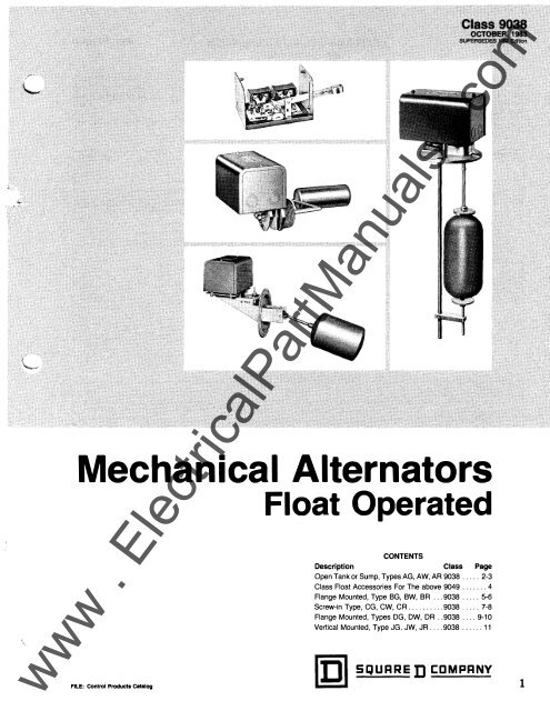
Mechanical Alternators<br />
FILE: Control Products Catalog<br />
Float Operated<br />
CONTENTS<br />
Description <strong>Class</strong> Page<br />
Open Tank or Sump, Types AG, AW, AR 9038 ..... 2-3<br />
<strong>Class</strong> Float Accessories For The above 9049 ....... 4<br />
Flange Mounted, Type BG, BW, BR ... 9038 ..... 5-6<br />
Screw-in Type, CG, CW, CR .......... 9038 ..... 7-8<br />
Flange Mounted, Types DG, DW, DR .. 9038 .... 9-10<br />
Vertical Mounted, Type JG, JW, JR .... 9038 ...... 11<br />
I• " SQUARED COMPANY<br />
www www . . <strong>Electrical</strong><strong>Part</strong><strong>Manuals</strong> <strong>Electrical</strong><strong>Part</strong><strong>Manuals</strong> . . com<br />
1
•<br />
MECHANICAL ALTERNATORS<br />
TYPES BG, BR, BW<br />
EXPLANATION OF FLOAT TRAVEL AND POSITION<br />
NORMAL OPERATION: Switches will cut in and cut out at REVERSE OPERATION (FORM R): Both pumps will be<br />
the high point and low point of distance A plus B, given in the running with the float at the low point of distance B. With the<br />
tables. Under normal conditions, as long as one pump alone is float rising to the top of distance B plus A, one pump will stop<br />
able to handle the incoming water, the pumps will alternate at and the other continue until the float reaches the high point of<br />
this distance. With the water level continuing to rise, the distance D. Both pumps will alternate between the distance C<br />
second switch will cut in and start the second pump when the<br />
float reaches the top of distance D. Both pumps will continue<br />
plus D.<br />
to run until the float returns to the low point of distance D plus<br />
C, where one pump will cut out. The other pump will continue<br />
until the float reaches the low point of distance B.<br />
I<br />
--<br />
H ---<br />
i�l·· f<br />
� I<br />
27" r ---632<br />
s<br />
7i6<br />
2599-133<br />
�-/4 PIPE_ TAP)<br />
-j-14 PIPE TAP<br />
Types BR, BW<br />
Net Weight 20 lbs.<br />
6-i r DIA. HOLES SPACED<br />
EQUALLY<br />
21�<br />
732<br />
Type BG<br />
Net Weight 10 lbs.<br />
POINT OF FLOAT TRAVEL: Figures I and 2, by reason of<br />
float rod casting shape, show position of float movement. In<br />
figure I, float movement is equally divided above and below<br />
center line. In figure 2, the main part of movement is below<br />
center line. Figure 3 is designed for vertical mounting.<br />
t<br />
4 13 );6 1.0. OF BEAD<br />
5 Yi'6 O.D. OF BEAD<br />
ORDERING INFORMATION REQUIRED:<br />
1. Specify <strong>Class</strong> 9038 Type .................. (Basic Switch) to the switch class and type, the suffix letters "BR" for Brass<br />
2. Specify <strong>Class</strong> 9049 Type ..................... (Rod Kit) Rod or "SR" for S.S. Rod, and "F" for Float.<br />
3. Specify <strong>Class</strong> 9049 Type ..................... (Float Kit) Example: To receive a 9038 BG-21, 9049 GBR-3 and 9049<br />
4. To receive a complete packaged alternator, that is, the three<br />
BF-1, complete, in one carton, specify: 9038<br />
above components packaged together in a single carton, add<br />
BG-21 BR3 Fl.<br />
www www . . <strong>Electrical</strong><strong>Part</strong><strong>Manuals</strong> <strong>Electrical</strong><strong>Part</strong><strong>Manuals</strong> . . com<br />
6 ----<br />
21<br />
JZ<br />
-- -- -- -- -- -- -- -- -- -- -- -- -- -- -- --<br />
- SQUARED COMPANY IDI
Revised Oct., 1983 MECHANICAL ALTERNATORS<br />
SCREW -IN TYPE FOR LIQUID LEVEL CONTROL IN<br />
CLOSED TANKS.<br />
UNITS INCLUDE FLOAT, ROD, SCREW-IN<br />
CONNECTOR.<br />
Buna N quad-ring seal packing is used between the float rod<br />
and sealing tube. Normal application is at atmospheric pressure,<br />
but where higher pressures are encountered the switch<br />
will withstand tank pressures up to 50 p.s.i. at temperatures up<br />
to 250°F. Occasional repacking may be necessary. A special<br />
Teflon® seal (Form ZlO) for pressures up to 100 p.s.i. can be<br />
furnished if specified.<br />
Float travel adjustments are external and an indicating scale is<br />
provided to facilitate settings. A pointer on the switch linkage<br />
indicates float position within the tank.<br />
<strong>Electrical</strong> Ratings - see page 11 .<br />
TYPES CG, CW, CR<br />
SCREW IN ALTERNATORS<br />
TWO 2 POLE UNITS<br />
CLASS 9038 CONTACTS CLOSE ON LIQUID RISE<br />
Type CG-2<br />
Float On<br />
Left<br />
Float Position<br />
Viewed from Front<br />
of Switch Facing<br />
Approx.<br />
Water Level<br />
Change NEMA 1 NEMA 4 *NEMA7,9<br />
Indicator Scale " R " Min Max Type Price Type<br />
Price Type Price<br />
Right 7" 6Y2" 13" CG-1 $154. CW-1<br />
Left 7" 6Y2" 13 " CG-2 154. CW-2<br />
Right 4%" 4" Y:¥4'' CG-3 154. CW-3<br />
Left 4%" 4" 7'14' CG-4 154. CW-4<br />
Right 5" 4'14'' 9114" CG-5 154. CW-5<br />
Left 5" 4'14" 9%" CG-6 154. CW-6<br />
* Su1table for hazardous locat1ons <strong>Class</strong> 1 diVISIOns 1 and 2, Groups C and D, <strong>Class</strong> 2. d1v1S1ons 1 and 2, Groups E. F and G<br />
" R "<br />
"H"<br />
A B<br />
4%" 5¥2" 2" 3112"<br />
5" 6%" 2114" 4"<br />
7" 8Y4" 2V2" 5"<br />
TABLE OF FLOAT TRAVEL ADJUSTMENTS<br />
FOR CLASS 9038 TYPE C<br />
Minimum<br />
c D<br />
2W' 3Y2"<br />
2'14" 4"<br />
2" 5"<br />
F<br />
7"<br />
8"<br />
10"<br />
A<br />
3W'<br />
3'14''<br />
5"<br />
$425. CR-1 $419.<br />
425. CR-2 419.<br />
425. CR-3 419.<br />
425. CR-4 419.<br />
425. CR-5 419.<br />
425. CR-6 419.<br />
Maximum<br />
B c D F<br />
4'14" 3 :V.." 4'14" 9¥2"<br />
5114" 3 " 5114" 10W'<br />
7" 4" 7" 14"<br />
EXPLANATION OF FLOAT TRAVEL AND AVAILABLE MODIFICATIONS<br />
POSITION NOTE: Standard materials are:<br />
NORMAL OPERATION: Switches will cut in and cut out at<br />
the high point and low point of distance A plus B, given in the<br />
Float: #304 S.S.<br />
Float rod: #316 S.S.<br />
Sealing tube: Brass<br />
tables. Under normal conditions, as long as one pump alone is<br />
2W' Bushing: Cast Iron<br />
able to handle the incoming water, the pumps will alternate at<br />
this distance. With the water level continuing to rise, the<br />
second switch will cut in and start the second pump when the<br />
float reaches the top of distance D. Both pumps will continue<br />
Packing: Buna N quad-ring<br />
Omit 2W' connecting bushing .<br />
OmitFioat .<br />
Manual transfer selector .<br />
(see 9038A section for details)<br />
. . Form F3 . . . . deduct .... $ 3 .<br />
. Form L .. .. deduct . 9 .<br />
. Form N3 . . . add . 21 .<br />
to run until the float returns to the low point of distance D plus Two level non-alternating unit. . Form N4 .add . 21.<br />
C, where one pump will cut out. The other pump will continue Addition of a third, high water alarm Circuit .. . . . Form N5 . . . . add . 50 •<br />
until the float reaches the low point of distance B.<br />
Reverse action (contacts open on Rise) . . Form R.<br />
. N.C .<br />
REVERSE OPERATION (FORM R): Both pumps will be<br />
running with the float at the low point of distance B. With the<br />
float rising to the top of distance B plus A, one pump will stop<br />
and the other continue until the float reaches the high point of<br />
distance D. Both pumps will alternate between the distance C<br />
plus D.<br />
TEFLON and VITON are registered trademarks of duPont<br />
Sub. #316 S.S. Float and sealing tube, Teflon® Packing .FormZ9 . . . add. 165 .<br />
Sub. Teflon® Packing. . . . . FormZ10 ... add. 33 .<br />
Sub. #316 S.S. Float, sealing tube, 2W' bushing, Teflon®<br />
Packing . .. FormZ14 ... add. . . 271.<br />
Viton® packing (Diesel Fuel) . . . FormZ19.<br />
ORDERING INFORMATION REQUIRED: Specify <strong>Class</strong>, Type, Form.<br />
IDI SQURRE: D CDMPRNY ---- -- -- -- -- 078 DISCOUNT<br />
www www . . <strong>Electrical</strong><strong>Part</strong><strong>Manuals</strong> <strong>Electrical</strong><strong>Part</strong><strong>Manuals</strong> . . com<br />
N.C .<br />
7
8<br />
MECHANICAL ALTERNATORS<br />
TYPES CG, CW, CR<br />
Type CG<br />
APPROXIMATE DIMENSIONS<br />
Type CG<br />
Net Weight - ?Y2 Pounds Approx.<br />
TypeCR, CW<br />
Net Weight - 21 Pounds Approx.<br />
!<br />
r-r, l j<br />
'�: :_ -- - -7<br />
15�-- -- ---<br />
www www . . <strong>Electrical</strong><strong>Part</strong><strong>Manuals</strong> <strong>Electrical</strong><strong>Part</strong><strong>Manuals</strong> . . com<br />
---- -- -- -- -- -- -- -- -- -- -- -- -- --<br />
�- -<br />
- SQUARED COMPANY IDI
Revised Oct., 1983 MECHANICAL ALTERNATORS<br />
TYPES DG, OW, DR<br />
BUILD UP THE SWITCH TO MEET YOUR REQUIREMENTS FROM THE BASIC SWITCH, ROD AND FLOAT GROUPS<br />
BELOW.<br />
EXPLANATION OF FLOAT TRAVEL AND POSITION<br />
NORMAL OPERATION: Switches will cut in and cut out at the high<br />
point and low point of distance A plus B, given in the tables. Under<br />
normal conditions, as long as one pump alone is able to handle the<br />
incoming water, the pumps will alternate at this distance. With the water<br />
Type DG<br />
Shown with Rod Kit<br />
level continuing to rise, the second switch will cut in and start the second<br />
9049 ER·5,<br />
pump when the float reaches the top of distance D. Both pumps will<br />
and Float Kit<br />
continue to run until the float returns to the low point of distance D plus<br />
9049 HF -3<br />
installed<br />
C, where one pump will cut out. The other pump will continue until the<br />
float reaches the low point of distance B.<br />
REVERSE OPERATION (FORM R): Both pumps will be running with<br />
the float at the low point of distance B. With the float rising to the top of<br />
distance B plus A, one pump will stop and the other continue until the<br />
float reaches the high point of distance D. Both pumps will alternate<br />
between the distance C plus D.<br />
These devices use graphite coated asbestos packing and are limited to 50<br />
P.S.I. tank pressure.<br />
FLANGE MoQN'riD �LJ'ERJUTOR5 {BASIC SWITCHES)<br />
CLASS 9038 CONTACTS CLOSE ON LIQUID RISE CONTROL OF LIQUID LEVEL WITHIN CLOSED TANKS<br />
Water Level<br />
Hinge Post<br />
Dimension<br />
NEMA 1 NEMA 4 NEMA 7 and 9*<br />
Poles Change "V" Type Price Type Price Type<br />
Price<br />
Min.<br />
2%"<br />
DG·? $167. OW·? $438. DR·?<br />
Two 2 Pole<br />
Max. DG·8 167. DW-8 438. DR·8<br />
Units Min.<br />
411f1s"<br />
DG·9 167. DW-9 438. DR·9<br />
Max. DG·10 167. DW·10 438. DR·10<br />
* Su1table for hazardous locations <strong>Class</strong> 1, diVISions 1 and 2, Groups C and D: <strong>Class</strong> 2, diVISIOns 1 and 2, Groups E. F and G<br />
SELECT CLASS 9049 ROD KITS FROM THESE TABLES OF FLOAT TRAVEL ADJUSTMENTS<br />
Type DG<br />
Li<br />
flOAT KIT$ fOR USE WITH 90380<br />
Size and Material <strong>Class</strong> and Type Price<br />
Diameter x Length<br />
3%" X 4W', #302 S.S. <strong>Class</strong> 9049 Type EF ·1 $12.<br />
3%"x 4Y2'', #316 S.S. <strong>Class</strong> 9049 Type EF·2 27.<br />
2W' X 7", #302 S.S. <strong>Class</strong> 9049 Type HF·3 13.<br />
2Y2'' X 7", #316 S.S. <strong>Class</strong> 9049 Type HF ·4 41.<br />
AVAILABLE MODIFICATIONS<br />
Manual transfer selector<br />
switch . . .......... Form N3 add $21.<br />
(see 9038 Type A for details)<br />
Two level,<br />
non-alternating unit . . .Form N4 add 21.<br />
Reverse action<br />
(contacts open on rise) ...... Form R N.C.<br />
<strong>Electrical</strong> Ratings - see page 11 .<br />
Rod Kit<br />
Ctass $049<br />
Type ER-1<br />
Type ER·2<br />
Type ER-3<br />
Type ER·5<br />
Type ER· 7<br />
Type ER·12<br />
RQdl(lt<br />
Cliiss 9049 ··<br />
Type ER-1<br />
Type ER·2<br />
Type ER-3<br />
Type ER·5<br />
Type ER· 7<br />
Type ER·12<br />
RodKlt<br />
· Cla$!i 9049<br />
Type ER·1<br />
Type ER·2<br />
Type ER-3<br />
Type ER·5<br />
Type ER· 7<br />
Type ER·12<br />
ROdKlt.<br />
C!Us$049.<br />
Type ER·1<br />
Type ER·2<br />
Type ER-3<br />
Type ER-5<br />
Type ER· 7<br />
Type ER·12<br />
r;:::;J � S[JURRE D CDMPRNY ---- -- -- - 078 DISCOUNT<br />
9038 TYPE DG-7, DR-7, DW-7 "V" = 2%" (MINIMUM LEVEL CHANGE)<br />
Minimum Travel Maximum Travel<br />
"R" e"H" G A B c D F G A B c D<br />
H'•" 8v." 1" '¥4 ' 5" 4" 1'¥4 ' 6'¥4" 1W' % " 5" 4W' 1V2"<br />
21f2" 9" 1" %" 5%" 4114" 1'¥4" 7Ye" 1Y2'' %" 5Y4" 4112" 1%"<br />
3W' 9W' 1" Vz" 5W' 4%" 1'¥•" 7W' 1W' 1f4" 5W' 4%" 1v .' '<br />
5Y4" 11'¥4" 1" Ya" 6%" 5" 1'¥4" 81Js" H'4" 0 6W' 5Vo" 1"<br />
7%" 13"'" 1" %" 7" SVz" 1'¥4'' 8'¥4" 2" Vz" 7" 5'¥4" 7/s "<br />
12v.'' 18"'" 1" %" 8%" 6'¥4'' 1'¥4 ' 10%" 2W' 1W' 8'¥4'' 7'¥4" %"<br />
9038 TYPE DG-8, DR-8, DW-8 "V" = 2%" (MAXIMUM LEVEL CHANGE)<br />
Minimum Travel Maximum Travel<br />
"R" e "H " G A B c D F G A B c D*<br />
H'•" 7V•" 1W' 0 8" 6W' 2" 10" 2Y2" 1v.'' 8" 6W' Y2"<br />
2W' 8W' 11Jz" 1f2" 8'¥4'' 7" 1'¥•" 10W' 2'¥•" 1W' 8'¥4" 7" Y4"<br />
3Y4" 9" H'4" 1" 9W' 7'¥4" 1W' 11" 3" 2" 9Yz" 7'12'' 0<br />
51/4" 11" 2" 2" 11W' 9W' 1W' 12'¥4" 3'¥4" 3" 11W' 9" ¥4''<br />
12V4'' 18" 2V4'' SW' 18W' 14'¥4" 1f2" 19" 6V4'' 6W' 18W' 15" 4v.''<br />
9038 TYPE DG-9, DR-9, DW-9 "V" = 411ilo" (MINIMUM LEVEL CHANGE)<br />
Minimum Travel Maximum Travel<br />
"R" e"H" G A B c D F G A B c D<br />
1l4" 81!4" 3" 1" 5W' 4V2" 2" 71!4" 31,/o" 1f2" 51!4" 41f2" 1Yz"<br />
2112" 9" 3" 1" 5"'" 4"'" 2" 7'¥•" 4" Ya" 5%" 4'¥4" 11!4"<br />
3V4 ' 9W' 3" Ya" 6" 5" 2" 8" 4" 0 5'/o ' 5" 1Vo"<br />
51f4" 11'¥4" 3" %" 7W' 5'¥4" 2" 9Y4'' 4%" 1fa" 71fa" 5'/o'' '¥4"<br />
7W' 13"'" 3V4'' Y4" 8W' 6W' 1 7/ o" 10Vo" 4%" 1%" 8V4 ' 6'¥4" 1f2"<br />
12V4'' 18'¥4" 4" Ya" 10'¥4" 8%" 1%" 12%" 5'¥4'' 2'/o'' 11" 8W' 112"<br />
9038 TYPE DG-10, DR-10, DW-10 "V" = 4"ilo" (MAXIMUM LEVEL CHANGE)<br />
Minimum Travel Maximum Travel<br />
"R" e"H" G A B c D F G A B c D*<br />
1'¥4" 7W' 3W' Y2" 8" 7" 1'¥4" 8'¥4" 4'¥4" 1V2" 8" 7" 11z"<br />
2W' 8V4'' 3V•" 1" 8'¥4" 7'¥4" 1'¥4" 10V2" 5" 2" 8'¥4" 7V." V4"<br />
3V4 ' 9" 3W' 1V2 ' 9V•" 8V4 ' 1V2'' 11" 5Y4" 2W' 9V." Bv." 0<br />
5V4 ' 11" 3'¥4" 2V2 ' 11W' 10" 1V4'' 12'¥4" 6" 4" 11V." 10" 1"<br />
7V4 ' 13" 4" 3W' 13W' 11W' 1" 14W' 6'¥4" SY2" 13W' 12" 1Vz"<br />
12v." 18" 4'¥4" 6" 18W' 15W' Y2" 19" 8W' 9V4'' 18W' 17" 2'¥4"<br />
• Add 2'h" to "H" If using 7" Long Floats, 9049 HF-3 or HF-4,<br />
* "D" will be negative when the top of the float I• below the hortzontel centerline.<br />
$432.<br />
432.<br />
432.<br />
432.<br />
F<br />
6Y2''<br />
6%"<br />
6'¥4"<br />
7W'<br />
77fo''<br />
9%"<br />
F<br />
8W'<br />
9"<br />
9W'<br />
10'¥4"<br />
7%" 13" 2" 3" 13W' 11" ¥4'' 14v.' ' 41f2" 4" 13W' 10'¥4" 1'¥4" 11'¥4"<br />
www www . . <strong>Electrical</strong><strong>Part</strong><strong>Manuals</strong> <strong>Electrical</strong><strong>Part</strong><strong>Manuals</strong> . . com<br />
14V4 '<br />
F<br />
6¥4"<br />
6'/o''<br />
7"<br />
7718"<br />
8'¥4"<br />
11V2 '<br />
F<br />
8V2''<br />
9"<br />
9V2"<br />
10V2''<br />
12"<br />
15'¥4"<br />
Price<br />
$5.<br />
5.<br />
5.<br />
5.<br />
5.<br />
5.<br />
Price<br />
$5.<br />
5.<br />
5.<br />
5.<br />
5.<br />
5.<br />
Price<br />
$5.<br />
5.<br />
5.<br />
5.<br />
5.<br />
5.<br />
Price<br />
$5.<br />
5.<br />
5.<br />
5.<br />
5.<br />
5.<br />
9
6 27/32-- ---- - -<br />
�<br />
�'<br />
�I<br />
.,,<br />
MECHANICAL ALTERNATORS<br />
TYPES DG, OW, DR<br />
�· --227/64 I 15/�(2JPLS- - I �21 7132-<br />
t<br />
I<br />
I<br />
519/32<br />
424D-85<br />
4 KNOCKOUT HLS FOR 1/2 8; 3/4<br />
£0�fOUIT ON -EAC_H_ END _ __ _ _<br />
___ j<br />
I<br />
i<br />
4240-81<br />
----H--·<br />
_j<br />
Type DG<br />
Net Weight - 7 Pounds Approx.<br />
Showing Hole in tank pattern.<br />
-j- CONDUIT CONNECTION<br />
ON BOTH ENDS---<br />
�---.<br />
-------- Types DR, OW<br />
Net Weight - 21 Pounds Approx .<br />
1<br />
/�<br />
(4)HLS 13/32Ditl<br />
NOTE: The recommended size of hole in the tank for the<br />
entry of the float and mounting of the control is 43hs''.<br />
Floats shown are Type EF, 4W' long.<br />
Add 2W' to "H" if using Type HF Floats which are 7" long.<br />
3: DIA. (4) HOLES<br />
ORDERING INFORMATION REQUIRED:<br />
1. Specify <strong>Class</strong> 9038 Type ........... ....... (Basic Switch) to the switch class and type, the suffix letters "R" for Rod and<br />
2. Specify <strong>Class</strong> 9049 Type ......... .. .......... (Rod Kit) "F" for Float.<br />
3. Specify Closs 9049 Type ..................... (Float Kit) Example: To receive a 9038 DG-7, 9049 ER-1 and 9049<br />
4. To receive a complete packaged alternator, that is, the three<br />
EF-1, complete, in one carton, specify: 9038 DG-7<br />
above components packaged together in a single carton, add<br />
Rl Fl.<br />
10<br />
www www . . <strong>Electrical</strong><strong>Part</strong><strong>Manuals</strong> <strong>Electrical</strong><strong>Part</strong><strong>Manuals</strong> . . com<br />
---- -- -- -- -- -- -- -- -- -- -- -- -- -- -- -- -- -- -- -- -- -- -- -- -- -- -- -- -- -- -- -- -- -- -- -- -- -- -- -- -- --<br />
- SQURRED CDMPRNY IJ:JI
Revised Oct., 1983 MECHANICAL ALTERNATORS<br />
TYPES JG, JW, JR<br />
Flange mounted vertical action. Units are complete including float.<br />
For restricted tank space or when larger water level changes are required than can be normally provided on the<br />
conventional float switches.<br />
These devices use graphite coated packing and are limited to 50 P.S.I. tank pressure.<br />
CLASS 9038 CONTACTS CLOSE ON LIQUID RISE<br />
Ground Link<br />
Length '"A''<br />
NEMA 1 NEMA 4 NEMA 7and9*<br />
Distance Type Price Type Price Type Price<br />
17" JG-1 $246. JW-1 $517. JR-1 $511.<br />
23" JG-2 256. JW-2 527. JR-2 521.<br />
29" JG-3 266. JW-3 537. JR-3 531.<br />
35" JG-4 276. JW-4 547. JR-4 541.<br />
Two2-Pole<br />
Units 41" JG-5 286. JW-5 557. JR-5 551.<br />
47" JG-6 296. JW-6 567. JR-6 561.<br />
53" JG-7 306. JW-7 5n. JR-7 571.<br />
59" JG-6 316. JW-6 587. JR -6 581.<br />
* SUitable for hazardous locat1ons <strong>Class</strong> 1. d1v1s1ons 1 and 2, Groups C and D. <strong>Class</strong> 2, d1v1S1ons 1 and 2, Groups E, F and G<br />
OPERATION<br />
Type J switches will cut in and cut out at the high point and low point of distance B (given in drawing at right) Under normal cond1tions with one<br />
pump able to handle mcoming water, the pumps will alternate at this distance (solid line floats represent the normal alternating points). With water<br />
level continuing to rise, the second switch will cut in and start the second pump when the float reaches top of distance D. Both pumps will run until<br />
float returns to low point of distance 0 where leading pump will cut off first, with lagging pump continuing to run until float returns to low point of<br />
distance B<br />
NOTE 1 Travels listed in Table 1 also apply to explosion-proof (JR) and water-tight (JW) versions<br />
NOTE 2 The cut-in point of the leading pump cannot be adjusted to less than 47116'' from the top of the tank. The cut-in point of the lagging pump<br />
cannot be adjusted to less than 3W' from the top of the tank.<br />
The cut-out point of the leading pump cannot be less than 6l'a'' plus the distance from the end of the guide rod to the bottom of the tank<br />
The cut-out point of the lagging pump cannot be less than SW' plus the distance from the end of the guide rod to the bottom of the tank<br />
NOTE 3: After first pump cuts on, an additional increase in water level of 13f1e" wi ll bring the second pump on.<br />
Dimensions on JW, JR types available on request Portion of switch above tank would be<br />
same as Type DR, DW, preceding page<br />
AVAILABLE MODIFICATIONS<br />
Omit Float and rod accessories ........ ....... Form L1 ...... .. deduct. ..... $28.<br />
Omit Rod accessories ..<br />
Manual transfer selector .<br />
(see 9036 Type A for details)<br />
Two level, non-alternating Mechanism .<br />
Reverse action (contacts open on Rise)<br />
Sub. #31 6 S.S. Float and rod accessories.<br />
. . Form L2 . .. deduct. 5.<br />
.. ... Form N3 . . ..... add 21.<br />
.Form N4.<br />
.... Form R .<br />
.add . 21.<br />
. .. N.C.<br />
.FormZ5<br />
A= 17" ....... add .... 106.<br />
A= 23" .add ........ 112.<br />
A= 29" . . .add ........ 118.<br />
A= 35" .add ...... 124.<br />
A= 41" ..... add . .. ... 130.<br />
A= 47" .. add . . 136.<br />
A= 53" ........ add ........ 142 .<br />
A= 59" . . add . 148.<br />
TABLE 1 - ADJUSTMENT IN INCHES<br />
"A "<br />
Link<br />
Water Le·;el Change to Effect<br />
Normal Alternation of Two Pumps<br />
Type Length Minimum Maximum<br />
JG-1 17"<br />
"B"<br />
47hs" 71f1f/'<br />
JG-2 23" 47As" 131M'<br />
JG-3 29" 47Ae'' 191M'<br />
JG-4 35" 4711s" 251As"<br />
JG-5 41" 47f1s" 31 1f1s"<br />
JG-6 47" 47hs" 371116''<br />
JG-7 53" 4711s" 431hs"<br />
JG-6 59" 4711s" 491hs"<br />
ELECTRICAL RATINGS<br />
Voltage Single Phase AC Polyphase AC DC<br />
115 2H.P. 3H.P. V2H.P.<br />
230 3H.P. 5 H.P. V2H.P .<br />
4601575 1 H.P.<br />
32 V• H.P.<br />
Control C�rcu1t Rat1ng NEMA 600A<br />
IDisQURRE D CDMPRNY ----<br />
-- -- -- -- 078 DISCOUNT<br />
4240·06<br />
Type JG-1<br />
www www . . <strong>Electrical</strong><strong>Part</strong><strong>Manuals</strong> <strong>Electrical</strong><strong>Part</strong><strong>Manuals</strong> . . com<br />
11
II II SQURRE D CDMPRNY<br />
12<br />
www www . . <strong>Electrical</strong><strong>Part</strong><strong>Manuals</strong> <strong>Electrical</strong><strong>Part</strong><strong>Manuals</strong> . . com<br />
10/83 CPG Printed in USA
SEPTEMBER, 1966<br />
Supersedes Price Sheet 9038,<br />
Page 1, dated September, 1960<br />
CLASS 90 38<br />
MECHANICAL ALTERN A TORS<br />
OPEN TANK OR SUMP OPERATION *<br />
CONTACTS CLOSE ON LIQUID RISE<br />
CLASS 9038<br />
Price Sheet PAGE 1<br />
LEVER ACTUATED<br />
NEMA 1 NEMA 4<br />
NEMA 7 and 9<br />
Groups C-G<br />
Float Rod General Purpose Water Tight<br />
Explosion Proof<br />
Poles "E" Distance<br />
Two 2 Pole Units . . . .<br />
Lever<br />
Figure No.<br />
. . . .<br />
Type<br />
AG-1<br />
Price<br />
I $4 3.60<br />
Type<br />
AW-1<br />
Price<br />
I $101 .50<br />
Type<br />
AR-1<br />
Price<br />
I $ 98 .50<br />
*Float and rod accessories not furmshed on "A" Types. Order from 9049 Pnce Sheet Page 1-2. A tapped at top float can be used 1f turbulence of the<br />
liquids is not severe. If a center hole float is used a compensating spring (Form C) must be added to support the weight of the rod<br />
are furnished as standard on the <strong>Class</strong> 9038 Type AW & AR switches.<br />
Compensating springs<br />
FLANGE MOUNTED ALTERNATORS (Bellows Seal)<br />
CLASS 90 38 CONTACTS CLOSE ON LIQUID RISE CONTROL OF LIQUID LEVEL WITHIN CLOSED TANK<br />
Two 2 Pole Units<br />
1 BG-7 $11 7. BW-7 $16 3. BR-7 $160.<br />
12" 2 BG-8 11 7. BW-8 163. BR-8 160 .<br />
3 BG-9 11 7. BW-9 16 3. BR-9 160.<br />
1 BG-10 11 7. BW-10 163. BR-10 160.<br />
14" 2 BG-11 117. BW-11 163. BR-11 160 .<br />
3 BG-12 11 7. BW-12 163. BR-12 160 .<br />
1 BG-13 117. BW-13 163. BR-13 160 .<br />
16" 2 BG-14 11 7. BW-14 16 3. BR-14 160.<br />
3 BG-15 117. BW-15 16 3. BR-15 160 .<br />
SCREW IN ALTERNATORS<br />
CLASS 90 38 CONTACTS CLOSE ON LIQUID RISE<br />
Poles Float Position<br />
Two 2 Pole Units<br />
General Purpose Water Tight Explosion-Proof<br />
Type Price Type Price Type Price<br />
Right CG-1 $ 70 . CW-1 $ 206. CR-1 $ 203.<br />
Left CG-2 70 . CW-2 206. CR-2 203.<br />
FLANGE MOUNTED ALTERNATORS<br />
CLASS 90 38 CONTACTS CLOSE ON LIQUID RISE CONTROL OF LIQUID LEVEL WITHIN CLOSED TANKS<br />
Poles<br />
-�---�-<br />
Hinge Post General Purpose Enclosure Water Tight<br />
11<br />
E" Distance Dimension<br />
"H" Type Price Type Price<br />
12" DG-1 $79.50 DW-1 $2 15.50<br />
14"<br />
2%"<br />
See Table I DG-2 79.50 DW-2 215.50<br />
Page 3<br />
16" DG-3 79.50 DW-3 215.50<br />
Two 2 Pole<br />
Units 12" DG-4 79.50 DW-4 215.50<br />
41 Yl6"<br />
14" See Table II DG-5 79. 50 DW-5 21 5.50<br />
Page 3<br />
16" DG-6 79. 50 DW-6 215.50<br />
SPECIAL FEATURES AND ACCESSORIES •<br />
Monel Bellows (B Types only) . . . . . . . • . . . . . . . . . . . . . . . . . . . . . . . . . . . . . . . . . . . . . . . . . . . . . . . . . . . . . . . . . . . . . . . .<br />
r<br />
G<br />
g�f}7�::�t!� ��p
9038 CLASS<br />
PAGE 2 Price Sheet<br />
MECHANICAL ALTERN A TORS<br />
TABLE OF OPERATING FORCES- TYPES AG, AR AND AW<br />
SEPTEMBER, 1966<br />
Supersedes Price Sheet 9038,<br />
Page 2, dated September, 1960<br />
Without length of Rod Which Can Be Supported<br />
Comp. Spring With Compensating Spring with Compensating Spring at Max Adjust.<br />
(To Trip (To Trip<br />
Type<br />
Force<br />
Up<br />
Force<br />
Down<br />
Max. Wgt. Down)<br />
of Rod Minimum<br />
&. Stops Fit. Wgt.<br />
Up)<br />
Minimum<br />
Fit. Buoy<br />
:j::<br />
Monel<br />
:j::<br />
Brass<br />
. :j::SII<br />
Steel<br />
:j::<br />
Alum.<br />
AG-1 (Min. lever Ext.) ..................... 10 oz. 14 oz. 48 oz. 21 oz. 32 oz. 6ft. 11 fl. 12ft. 35 ft.<br />
AG-1 (Max. Lever Ext.) ..................... 8 12 40 15 20 5 9 10 28<br />
AG-1 Form R (Min. Lever Ext.) ...... ...... . 7 5 32 11 24 3 7 7 21<br />
AG-1 Form R (Max. lever Ext.) ............. 6 4 28 10 20 3 5 6 18<br />
AR-1, AW-1 (Standard lever) ................ 7 7 72 32 36 12 23 25 72<br />
AR-1 Form R, AW-1 Form R (Std. Lever). . • . 9 4 90 32 34 15 18 18 55<br />
:j:: Rod length has been determined using weight of rod material furnished on <strong>Class</strong> 9049 accessories.<br />
TABLES OF FLOAT TRAVEL ADJUSTMENTS<br />
FLANGE MOUNTED ALTERNATORS- TYPES BG, BR AND BW<br />
FIGURE I CASTING<br />
MINIMUM TRAVEL MAXIMUM TRAVEL<br />
"E"<br />
Distance A B c D F A B c D F<br />
--- --- --- --- --- --- --- --- ---<br />
12" 4l/a" 6Va" 4Va" 6Va" 12l4. 7%" 9Y," 7%" 9Y," 19"<br />
--- --- --- --- --- --- --- --- ---<br />
14" 4V." 6%" 4Y," 6%" 13Y," 8%" 10%" 8l/a" 10%" 21 V."<br />
--- --- --- --- --- --- --- --- ---<br />
16" 5" 7Y," 5" 7V." 15" 9%" 12" 9l4" 12" 24"<br />
FIGURE II CASTING<br />
"E"<br />
MINIMUM TRAVEL MAXIMUM TRAVEL<br />
Distance A B c D F A B c D F<br />
--- --- --- --- --- --- --- --- ---<br />
12" 1" 9Y," 8%" 2Yl•" 11'Jii•" 1 " lOY," 9Y," 2Yl•" 12'Jii••<br />
--- --- --- --- --- --- --- --- --- ---<br />
14" Y2" 11 n 9V." 2Yls" 131�6" V." 12Va" 10%" 2Y,•" 14"%•"<br />
--- --- --- --- --- --- --- --- --- ---<br />
16" Va" 12Y,•" 10%" 2Yl•" 14%" V2" 13'Yt•" 12" 2Yl•" 16"<br />
FIGURE Ill CASTING<br />
MINIMUM TRAVEL MAXIMUM TRAVEL<br />
"E"<br />
Distance A B c D F A B c D F<br />
--- --- --- --- --- --- --- --- --- ---<br />
12" Va" 10%" 9%" 1l4" 12" Va" 10%" 9%" 1Y4" 12"<br />
--- --- --- --- --- --- --- --- ---<br />
14" %" 12%" 11 Va" "Va" 13l4" %" 13" 11%" "Va" 13%"<br />
--- --- --- --- --- --- --- --- --- ---<br />
16" 1%" 13%" 12V2" % " 14Y," 1 l4. 15Va" 13%" % " 15%"<br />
•NOTE: When F distance is not specified, switches will be furnished with minimum float travel.<br />
EXPLANATION OF FLOAT TRAVEL AND POSITION<br />
NORMAL OPERATION: Standard Type BG, CG and DG<br />
switches will cut in and cut out at the high point and low point<br />
of distance A plus B, given in tables above. Under normal conditions,<br />
as long as one pump alone is able to handle the incoming<br />
water, the pumps will alternate at this distance. With the<br />
water level continuing to rise, the second switch will cut in and<br />
start the second pump when the float reaches the top of distance<br />
D. Both pumps will continue to run until the float returns to the<br />
low point of distance D plus C, where one pump will cut out.<br />
The other pump will continue until the float reaches the low<br />
point of distance B.<br />
---- -- -- -- -- -- SQUARED<br />
REVERSE OPERATION (FORM R): Both pumps will be running<br />
with the float at the low point of distance B. With the float<br />
rising to the top of distance B plus A, one pump will stop and<br />
the other continue until the float reaches the high point of distanceD.<br />
Both pumps will alternate between the distance C plus D.<br />
POSITION OF FLOAT TRAVEL: Figures 1 and 2, by reason<br />
of float rod casting shape, show position of float movement. In<br />
figure 1, float movement is equally divided above and below<br />
center line. In figure 2, the main part of float movement is<br />
below center line. Figure 3 is designed for vertical mounting.<br />
I:DMPRNY ---- -- -- -- -- --<br />
www www . . <strong>Electrical</strong><strong>Part</strong><strong>Manuals</strong> <strong>Electrical</strong><strong>Part</strong><strong>Manuals</strong> . . com<br />
SCHEDULE X DISCOUNTS Prices Subject to Change without Notice.
OCTOBER, 1958<br />
Supersedes Price Sheet 9038<br />
Page 2, Dated June, 1956<br />
(Minor Revision 6/64)<br />
(Minor Correction -1 0/67)<br />
�--- -- -[---- --�<br />
ClaiS 9038<br />
Type CG<br />
<strong>Class</strong> 9038<br />
Type DG<br />
:j:See Page 2 for explanation of float travel and position.<br />
MECHANICAL ALTERN A TORS<br />
TABLES OF FLOAT TRAVEL ADJUSTMENTS*<br />
SCREW-IN ALTERNATORS-- TYPE CG<br />
Di�t� ·<br />
---- -- -- -- -- -- SQUARED<br />
Prices Subject to Change Without Notice.<br />
�ce --A<br />
TYPE CG SCREW-IN ALTERNATORS<br />
CLASS 9038<br />
Price Sheet PAGE 3<br />
APPRO X.<br />
WATER<br />
LEVEL<br />
MINIMUM TRAVEL MAXIMUM TRAVEL CHANGE ·-�<br />
C<br />
C D -� . -<br />
F Min./ Max.<br />
·� B<br />
I<br />
I<br />
Dl F<br />
- A �- B -�<br />
8!4" 2Y," 4%" 2%" 4%" 9" 6" 7" 6!4" 7" 14" 6Y," 13"<br />
FLANGE MOUNTED ALTERNATORS-- TYPE DG<br />
APPROXIMATE DIMENSIONS<br />
"E"<br />
Distance A<br />
B<br />
eTABLE I (2%" "H" DIMENSION)<br />
MI NIMUM TRAVEL MAXIMUM TRAVEL<br />
c D F G A<br />
B<br />
c D F<br />
------ --- --- -- --- -- --- --- -- --- -- ---<br />
12" .. 5%" 4r.," ¥a '/<br />
6!;2" 1%" **" 5%" 4%" 1%" 7%"<br />
----- -- -- -- -- -- -- -- -- -- -- -- --<br />
14" %" 6!.6" 5V2." V2" 7" 2Va" *V. " 6!;2" 5%" 1% " 8!4"<br />
----- -- -- -- -- -- -- -- -- -- -- -- --- -<br />
16" %" 7Va" 5%" %" 7%" 2Va" *V2" 7�" 5%" 1%" 8r., n<br />
* Float projects above centerlme at max1mum travel adjustment.<br />
NOTE: "F" indicates actual float travel, "G" is distance from flange to highest point of float.<br />
"F" plus "G" must not exceed maximum "F" + 1¥16". When ''G" and 11F" are not<br />
specified on orders, switches will be furnished with Min. "G11 and Min. "F".<br />
"E"<br />
Distance A<br />
B<br />
TABLE II (41Y,•" "H" DIMENSION)<br />
MI NIMUM TRAVEL MAXIMUM TRAVEL<br />
·--<br />
c D F G A<br />
B<br />
c D F<br />
---- --- --- --- --- --- --- ---- --- --- --- --- --<br />
12" .. 6!4" 5%" %" 7" 3Va" **" 6!4" 5%" 1r.," 8Ys"<br />
------ -- -- -- --- --- -- -- -- -- -- -- -- --<br />
14" V." 7!4" 6�" %" 7%" 3Ys " *Y2" 7!4" 6�" 1%" 9 "<br />
---- --- -- -- -- -- -- -- -- -- -- -- --<br />
16" 1V4" 8!4" 6'Va" 8!4" 3Ya" *Va" 8!4" 6'Va" 1�.· 9% "<br />
* Float projects above centerline at max1mum travel adjustment.<br />
NOTE' "F" indicates actual float travel, "G" is distance from flange to highest point of float.<br />
"F" plus 11G" must not exceed maximum "F" + 3Vs". When "G" and "F" are not<br />
specified on orders, switches will be furnished with Min. "G" and Min. "F".<br />
G<br />
---<br />
lo/16"<br />
1VJ6"<br />
1 o/16"<br />
G<br />
4"<br />
4%"<br />
4%"<br />
•Revised<br />
I:DMPRNY ---- -- -- -- -- --<br />
www www . . <strong>Electrical</strong><strong>Part</strong><strong>Manuals</strong> <strong>Electrical</strong><strong>Part</strong><strong>Manuals</strong> . . com<br />
SCHEDULE X DISCOUNTS
www www . . <strong>Electrical</strong><strong>Part</strong><strong>Manuals</strong> <strong>Electrical</strong><strong>Part</strong><strong>Manuals</strong> . . com
SEPTEMBER, 1966<br />
New Sheet<br />
TYPE AG-1 MECHANICAL ALTERN A TOR<br />
with FORM N5 HIGH WATER ALARM modification<br />
The <strong>Class</strong> 9038 AG-1 mechanically alternates the operation<br />
of two sump pumps in a duplex system having a common<br />
tank. By alternating the cycles of operation, even wear of<br />
the two pumping units is insured and the evils of long stand<br />
by for one of the two pumps is eliminated. In addition, the<br />
AG-1 starts the second pump when extra capacity under<br />
peak conditions is required.<br />
If for any reason both pumps together are unable to control<br />
the rising of liquid in the tank, the Form NS snap switch<br />
mechanism is tripped energizing the high water alarm circuit.<br />
Float and Rod Accessories<br />
The <strong>Class</strong> 9049 Type A-6 float and rod accessories listed on<br />
<strong>Class</strong> 9049 Price Sheet Page 1 are recommended for use with<br />
the 9038 AG-1. Specifications for these accessories appear on<br />
<strong>Class</strong> 9049 Price Sheet Page 2.<br />
A tapped at top float can be used if turbulence of the liquid<br />
is not severe. The buoyancy of the float must be greater than<br />
the weight of the rod plus the weight of the stops plus the force<br />
to trip the switch up.<br />
If a center hole float is used, a compensating spring (Form C)<br />
must be added to support the weight of the rod. The switch<br />
then supports the weight of the rod and stops and the buoyancy<br />
of the float need be enough only to trip the switch up.<br />
Voltage<br />
115<br />
230<br />
440-550<br />
32<br />
ELECTRICAL RATINGS<br />
Single Phase<br />
AC<br />
1Y2 H.P.<br />
2 H.P.<br />
Lever Extension Position<br />
(See 9038 Dimension<br />
Sheet Page 1)<br />
Poly Phase<br />
AC DC<br />
2 H.P.<br />
3 H.P.<br />
1 H.P.<br />
- - ---<br />
·- - -<br />
- ---<br />
I<br />
Y2 H.P.<br />
-<br />
Y2 H.P.<br />
-- ---- - --<br />
Y4 H.P.<br />
OPERATING FORCES<br />
<strong>Class</strong> 9038 Type AG-1 Form N5<br />
CLASS 9038 CONTACTS CLOSE ON<br />
LIQUID RISE<br />
--<br />
-<br />
-- -- �<br />
--(l_ ---<br />
_<br />
1- _:�:-�:-�-N- 5 ___+_--<br />
�T ·<br />
w<br />
--<br />
o<br />
-<br />
2<br />
·p-;-;-::-<br />
U<br />
-- -<br />
nit s<br />
_<br />
AG-1 Form CN5<br />
9038 AG-1 Form N5<br />
Without Compensating<br />
Spring<br />
9038 AG-1 Form CN5<br />
With Compensating Spring<br />
Force to<br />
Tnp Up I<br />
Force to<br />
Tnp Down<br />
M<br />
�( R�t<br />
and Stops<br />
Min. Wgt.<br />
of Float to<br />
Trip Down<br />
21 oz.<br />
Min.<br />
Buoyancy<br />
of Float to<br />
Trip Up<br />
34 oz.<br />
_<br />
CLASS 9038<br />
Price Sheet PAGE 4.1<br />
·-l :n;:: r<br />
LEVER ACTUATED<br />
;<br />
_<br />
Price<br />
$6 6.10<br />
Two 2 Pole Units I NEMA 1 75.90<br />
<strong>Class</strong> 9049 A6 Accessories<br />
Length of Rod Which Can Be Supported With<br />
Compensating Spring at Maximum<br />
Monel Brass<br />
Stainless<br />
Steel Aluminum<br />
-------------- ----- ------ ---------------/ ------------ ----- ---- -----<br />
. ----� inim _� Leve_ ���-. _2__: �-� ���-- 48 oz.<br />
Maximum Lever Ext. 10 oz. 12 oz. 40 oz.<br />
15 oz.<br />
- 22-;;- t 6ft.<br />
5 ft.<br />
Note: For Outline Dimensions See 9038 AG-1 on<br />
9038 Dimension Sheet Page 1<br />
---- -- -- -- -- -- SQUARED COMPANY---- -- -- -- -- --<br />
www www . . <strong>Electrical</strong><strong>Part</strong><strong>Manuals</strong> <strong>Electrical</strong><strong>Part</strong><strong>Manuals</strong> . . com<br />
Prices Subject to Change without Notice. SCHEDULE X DISCOUNTS<br />
11 ft.<br />
9ft.<br />
12 ft.<br />
10 ft.<br />
35 ft.<br />
28ft.
www www . . <strong>Electrical</strong><strong>Part</strong><strong>Manuals</strong> <strong>Electrical</strong><strong>Part</strong><strong>Manuals</strong> . . com<br />
.�
OCTOBER, 1963<br />
New Sheet<br />
MECHANICAL ALTERNATORS - FLANGE MOUNTED<br />
VERTICAL ACTION<br />
AUTOMATIC CONTROL OF LIQUID LEVEL WITHIN CLOSED TANKS<br />
CLASS 9038 CONTACTS CLOSE ON LIQUID RISE<br />
Two<br />
2-Po/e<br />
Units<br />
Type<br />
TABLE 1- ADJUSTMENT IN INCHES<br />
"A" "B"<br />
Link<br />
Water Level Change to Effect<br />
Length<br />
Normal Alternation of Two Pumps<br />
OPERATION<br />
Type J switches will cut in and cut out at the high point and low point of distance B (given in drawing at<br />
right). Under normal conditions with one pump able to handle incoming water, the pumps will alternate<br />
at this distance (solid line floats represent the normal alternating points). With water level continuing to<br />
rise the second switch will cut in and start the second pump when the float reaches top of distance D. Both<br />
pu,;ps will run until float returns to low point of distance D where leading pump will cut off first, with<br />
Jagging pump continuing to run until float returns to low point of distance C.<br />
NOTE 1: Travels listed in Table 1 also apply to explosion-proof (JR) and water-tight (JW) versions.<br />
NOTE 2: The cut-in point of the leading pump cannot be adjusted to Jess than 4!1,•" from the top of the<br />
tank. The cut-in point of the lagging pump cannot be adjusted to less than 3�" from the top<br />
of the tank.<br />
The cut-out point of the leading pump cannot be less than 6)/g" plus the distance from the end<br />
of the guide rod to the bottom of the tank.<br />
The cut-out point of the Jagging pump cannot be less than 5Y2" plus the distance from the end<br />
of the guide rod to the bottom of the tank.<br />
ELECTRICAL RATINGS<br />
Voltage Single Phase AC<br />
115... 1Yz HP.<br />
230 ................. 2HP. 440 550 ... .<br />
32.<br />
SPECIAL FEATURES AND ACCESSORIES [�(t�r I<br />
Stai�l;ss Ste�J Float - ;ndR�� -<br />
Price<br />
--- --<br />
�- -- Form Z5 r $so.<br />
Polyphase AC<br />
2 HP.<br />
3 HP.<br />
...... 1 HP.<br />
DC<br />
. Yz HP<br />
Y2 HP<br />
V. HP<br />
A<br />
8<br />
CLASS 9038<br />
Price Sheet PAGE 5<br />
VERTICAL MOUNTING<br />
\, ---11--<br />
11<br />
,,<br />
I<br />
ORDERING INSTRUCTIONS<br />
!-Specify <strong>Class</strong> 9038 Type .....<br />
',<br />
'<br />
'<br />
\<br />
\<br />
I<br />
I<br />
I<br />
I<br />
I<br />
2188-GIO<br />
3.L<br />
I<br />
4<br />
D C<br />
2-lf special features are desired, add the appropriate Form<br />
. .. . . to the <strong>Class</strong> and Type. Arrange Form letters in<br />
alphabetical sequence when ordering more than one special<br />
feature.<br />
---- -- -- -- -- -- - SQUARE D COMPANY ----<br />
www www . . <strong>Electrical</strong><strong>Part</strong><strong>Manuals</strong> <strong>Electrical</strong><strong>Part</strong><strong>Manuals</strong> . . com<br />
Prices Eubject to Change without Notice.<br />
SCHEDULE X DISCOUNTS<br />
-- -- -- -- -- -
www www . . <strong>Electrical</strong><strong>Part</strong><strong>Manuals</strong> <strong>Electrical</strong><strong>Part</strong><strong>Manuals</strong> . . com
[g) · -- MAY, 1960 ----<br />
APPLICATION<br />
<strong>Class</strong> 9038 Mechanical Alternators are designed to provide<br />
a simple positive means of mechanically alternating the operation<br />
of two pumps installed in a duplex system with a common<br />
tank. The function of these controls is to provide alternate<br />
cycles of operation to insure even wear of the pumping units.<br />
They thus eliminate the evils of long stand-by for one of the<br />
two pumps. These alternators further provide the additional<br />
function of starting the second pump in cases where extra<br />
capacity under peak conditions is required.<br />
Poles - Mechanical Alternators consist of two 2 pole units<br />
with double break silver to silver contacts.<br />
<strong>Electrical</strong> Ratings - Ratings indicated on List Price Sheet.<br />
Enclosures - General Purpose Enclosures are of heavy<br />
gauge sheet steel finished in blue-gray enamel. The modern<br />
styled slip-on cover can easily be removed to allow access to<br />
the switch interior.<br />
Type AR, BR, CR and DR enclosures are designed for operation<br />
where <strong>Class</strong> I Group D hazardous locations are encountered.<br />
This housing meets the latest requirements for applications<br />
in vapor air mixtures of duco, lacquers, thinners, ethyl<br />
alcohol, methyl alcohol, acetone and petroleum products.<br />
Water-tight enclosures have the same general construction<br />
features as the Type AR, BR, CR and DR enclosures with the<br />
addition of a gasket to provide a water-tight seal.<br />
Operation<br />
The heart of the <strong>Class</strong> 9038 is a unique, yet simple, linkage<br />
which causes alternate operation of two pumping units on successive<br />
cycles. As long as a single pump can handle the<br />
pumping demand, this alternation of units continues. However,<br />
under peak condition, when the liquid level continues<br />
to rise or fall more rapidly than can be handled by one pump,<br />
both pumping units are automatically placed in operation.<br />
Both units will continue to operate until such time as a single<br />
pump can again handle the load. Alternate cycling is then<br />
automatically resumed. When the pump fails or becomes inoperative<br />
for some reason other than line voltage failure, the<br />
alternator will continue to function and will assure operation<br />
of the remaining pump.<br />
Alternators can be furnished in standard (contacts close<br />
on liquid rise) or reverse (contacts open on liquid rise) action.<br />
The changeover from Standard to Reverse operation should<br />
never be attempted in the field.<br />
All types can be furnished with a lead-lag selector. This<br />
manually engaged selector voids alternation ....... The Pump<br />
selected to lead always comes on first, with the second (lag)<br />
pump operating only under peak demand conditions, or when<br />
first pump fails. With selector disengaged, the unit reverts to<br />
normal alternation. Form N3 cannot be added to existing units<br />
in the field.<br />
Supersedes Descriptive ShoAt 9038,<br />
Page 2, dated May, 1958<br />
<strong>Class</strong> 9038 Type AR<br />
CLASS 9038<br />
-- -ffiECHRmcnL RLTERnRTOR<br />
AG Types<br />
The AG Types are for use with open tank or sump<br />
pumps.<br />
The contact blocks are of heavy non carbonizing melamine<br />
with contacts of laminated bronze and silver.<br />
Three concentric knock-outs for liz" or 3,4" conduit<br />
are provided. Operating lever is extendable from 31/z" to<br />
4o/!6". Contacts close at high liquid level on standard controls.<br />
BG Types<br />
The BG Switch Mechanism is essentially the same as on<br />
AG Types. This assembly is flange mounted and includes<br />
a float travel adjustment, bellows seal, float, rod and an<br />
operating lever which transmits float motion to the switch.<br />
<strong>Class</strong> 9038 Type BR<br />
For sump or open<br />
tank use.<br />
<strong>Class</strong> 9038 Type BG<br />
SQUARE D COMPANY----<br />
www www . . <strong>Electrical</strong><strong>Part</strong><strong>Manuals</strong> <strong>Electrical</strong><strong>Part</strong><strong>Manuals</strong> . . com<br />
Descriptive Sheet- PAGE 1<br />
-- -- -- -- --
9038 CLASS<br />
ffiECHRniCRL RLTERnRTOR----<br />
<strong>Class</strong> 9038<br />
Type CG<br />
<strong>Class</strong> 9038<br />
Type DG<br />
<strong>Class</strong> 9038<br />
Type DG<br />
Cover Removed<br />
to Show Switch<br />
---- -- -- -- --<br />
Interior<br />
--MAY,1960-�<br />
For higher tank pressures (to 100 P.S.I. at 275 o F.) a Monel<br />
bellows (Form A) can be furnished. Specify Form ZS if a stainless<br />
steel float and rod are desired.<br />
Three types of operation are available. Figure 1 provides<br />
for an equal amount of float movement on either side of the<br />
switch centerline. Figure 2 operation limits most of the float<br />
movement to below the centerline. Figure 3 provides for<br />
vertical mounting. (See list price sheet for float travels.) Standard<br />
operation provides for closed contacts at high liquid level.<br />
CG Types<br />
Complete units in themselves these controls consist of the<br />
switch mechanism proper, copper coated float, linkage to<br />
transmit float movement to the switch and a 2:Y::;-inch screwin<br />
connection.<br />
Graphite coated asbestos packing is used between the float<br />
rod and sealing tube. The controls are available with a stainless<br />
steel float, rod and sealing tube for use with corrosive liquids.<br />
Specify Form Z9.<br />
Normal application is at atmospheric pressure, but where<br />
higher pressures are encountered the switch will withstand<br />
tank pressures up to 50 P.S.I. at temperatures up to 250° F.<br />
Occasional re-packing may be required. A special Teflon seal<br />
(Form Z10) for pressures up to 100 P.S.I. can be furnished if<br />
specified.<br />
Float travel adjustments are external and an indicating scale<br />
is provided to facilitate settings. A pointer on the switch linkage<br />
indicates float position within the tank when the unit is<br />
mounted.<br />
For polyphase service these switches may be used, to advantage,<br />
in the control circuit of the proper motor starter.<br />
Four concentric knock-outs for Y2" or %:" conduit are<br />
provided.<br />
Standard operation provides for closed contacts at high<br />
liquid level. Reverse action (Form R) can also be supplied.<br />
Switch action can be reversed easily in the field simply by<br />
locating link piece in opposite hole of adjusting plate and the<br />
corresponding slot in baseplate of switch mechanism.<br />
DG Types<br />
The <strong>Class</strong> 9038 Type DG flange mounted mechanical alternators<br />
are designed for applications where mounting is to be<br />
made at the top of a closed tank. The unit is completely selfcontained<br />
and consists of an alternator mechanism, mounting<br />
flange, linkage to transmit float movement to switch, float rod<br />
and a cylindrical float.<br />
The mounting flange is a brass forging. <strong>Part</strong>s to be immersed<br />
in liquid are brass or stainless steel. Float is composed of copper<br />
coated steel, and all interior parts of switch mechanisms<br />
are plated for corrosion resistance. A stainless steel float (Form<br />
ZS) is available for use with corrosive liquids.<br />
Graphite coated asbestos is used in stuffing box which<br />
transmits motion of float. This insures a water-tight seal.<br />
Switches are mounted by fastening the flange to the tank<br />
by means of supporting bolts. See the dimension drawings for<br />
bolt centers.<br />
Four concentric knock-outs for :Y2" or %" conduit are<br />
provided.<br />
Adjustment of float travel in field within moderate limits<br />
is possible without removing unit from tank.<br />
-- SIJ UARE D COMPANY---- -- -- -- -- --<br />
www www . . <strong>Electrical</strong><strong>Part</strong><strong>Manuals</strong> <strong>Electrical</strong><strong>Part</strong><strong>Manuals</strong> . . com<br />
PAGE 2- Descriptive Sheet Supersedes Descriptive Sheet 9038,<br />
Page 2, Dated May, 1958
Ml<br />
�--OCTOBER, 1963<br />
APPLICATION<br />
The <strong>Class</strong> 9038 Types JG, JW, and JR flange mounted, ver<br />
tical action alternators are especially suitable for applications<br />
involving restricted tank space, or when larger water level<br />
changes are required than can be normally provided on the<br />
conventional angular movement type of float switches.<br />
Poles -- - Mechanical Alternators consist of two 2 pole units<br />
with double break silver to silver contacts.<br />
Elec:bic:al Ratings - Ratings indicated on List Price Sheet.<br />
Enclosures - General Purpose Enclosures are of heavy<br />
gauge sheet steel finished in blue-gray enamel. The modern<br />
styled slip-on cover can easily be removed to allow access to<br />
the switch interior.<br />
Type JR enclosures are designed for operation where <strong>Class</strong><br />
I Group D hazardous locations are encountered. This housing<br />
meets the latest requirements for applications in vapor air<br />
mixtures of duco, lacquers, thinners, ethyl alcohol, methyl<br />
alcohol, acetone and petroleum products.<br />
Water-tight enclosures have the same general construction<br />
features as the Type JR with the addition of a gasket to provide<br />
a water-tight seal.<br />
FEATURES<br />
The 9038 JG, JW, and JR controls are completely self-con·<br />
tained units composed of switch mechanism, mounting flange,<br />
linkage to transmit float movement to switch, center hole float<br />
and float rod.<br />
The mounting flange is a brass forging. <strong>Part</strong>s to be immersed<br />
in liquid are brass or stainless steel. Float is composed of cop<br />
per coated steel, and all interior parts of switch mechanism are<br />
plated for corrosion resistance. Specify Form Z5 to obtain<br />
----<br />
CLASS 9038<br />
-ffiecunmcnL RLTERnRTOR<br />
<strong>Class</strong> 9038<br />
Type JG- 1<br />
stainless steel float, float rod, ground link and guide for corro<br />
sive applications.<br />
Graphite coated asbestos is used in stuffing box which<br />
transmits motion of float. This insures a water·tight seal.<br />
Switches are mounted by fastening the flange to the tank<br />
by means of supporting bolts. See the dimension drawings for<br />
bolt centers.<br />
Adjustment of float travel can be made by increasing or de<br />
creasing the distance between the stop collars. Limits of float<br />
travel are indicated on the list Price Sheet, Page 5.<br />
---- -- -- -- -- -- SQUARE COMPANY----<br />
D<br />
New Sheet Desr.riptive Sheet PA GE 3<br />
www www . . <strong>Electrical</strong><strong>Part</strong><strong>Manuals</strong> <strong>Electrical</strong><strong>Part</strong><strong>Manuals</strong> . . com<br />
-- -- -- -- --
9038 CLASS<br />
ffiECHAntCAL ALTERnATOR----<br />
PAGE 4- Descriptive Sheet<br />
CD<br />
Approximate Dimensions<br />
10<br />
0<br />
'-'<br />
(2) K.os FoR !t2- 3 4<br />
COND. ON EACH END _<br />
<strong>Class</strong> 9028 Type JG<br />
4240- 86<br />
- OCTOBER, 1963--��<br />
��<br />
SQUARE D COMPANY---- -- -- -- -- -<br />
www www . . <strong>Electrical</strong><strong>Part</strong><strong>Manuals</strong> <strong>Electrical</strong><strong>Part</strong><strong>Manuals</strong> . . com<br />
N<br />
New Sheet
��-<br />
1-1•---6 {---<br />
Instruction Sheet L-4084<br />
DECEMBER. 1955 ----<br />
-- -- --1<br />
i-14PIPE TAP<br />
�-14PIPETAP<br />
CLASS 9038 TYPES BR, BW<br />
Net Weight 20 pounds approx<br />
Instruction Sheet L-4163<br />
CLASS 9038 TYPE BG<br />
Net Welght-10 Pounds<br />
2"t·CI<br />
---- -- -- -- -- -- -- -<br />
•::?�o<br />
Approximate Dimensions<br />
�-4-t_��--�·-· ��<br />
, POS.3
9038 CLASS<br />
ffiECHRniCRL ALTERnATOR----<br />
Instruction Sheet L-4176<br />
CLASS 9038 TYPE CG<br />
Net Wel!lht 7:V. pounds approx.<br />
r--<br />
4240-BI<br />
·� --l'<br />
2i{-<br />
Approximate Dimensions<br />
E<br />
����T;�uNTE�'tHE�:g.R 112 831�-----� - .<br />
CLASS 9038 TYPE DG<br />
Net Wei!lht 7 pounds approx.<br />
II II<br />
DECEMBER, 1955 ____<br />
4!!. � --<br />
16<br />
��-<br />
�� - - -�<br />
���<br />
,__ __ ..,.......; ;,:===<br />
--- �� ��<br />
1_<br />
II "<br />
(�) )..fQ_L,�S � 'DIA.<br />
NOTE: The recommended size of hole in the<br />
tank for the entry of the float and mounting of<br />
the control is 4%".<br />
• Instruction Sheet L-4183-(Refer to <strong>Class</strong> 9038 Price Sheet Page 1-2 for further information on DRWG. 4240-81)<br />
• Revised<br />
---- -- -- -- -- -- SQUARE D COMPANY---- -- -- -- -- --<br />
www www . . <strong>Electrical</strong><strong>Part</strong><strong>Manuals</strong> <strong>Electrical</strong><strong>Part</strong><strong>Manuals</strong> . . com<br />
PAGE 2- Dimension Sheet Dimensions Subject to Change without Notice.<br />
Supersedes Descriptive Sheet 9038, Page 2, dated January, 1955<br />
(Minor Corrections 1 /66)
U II __<br />
Instruction Sheet L-4214<br />
_l _n::.:s.:.tr<br />
-<br />
u<br />
ction<br />
_<br />
-_<br />
s<br />
h<br />
CLASS 9038<br />
DECEMBER, 1962 ----me c H n n 1 c n L R L TERn nT oR<br />
eet<br />
L<br />
_ _<br />
-��<br />
"' \\ �<br />
\<br />
f*2_�-,--+·<br />
2<br />
4<br />
-<br />
_<br />
I I<br />
_./;/<br />
-v--<br />
Di mansions Subject to Change without Notice.<br />
New Sheet<br />
1 5<br />
Approximate Dimensions<br />
-IN<br />
C3005 1-00/<br />
CLASS 9038 TYPE CH<br />
Net Wei�ht - 21 Pounds Approx.<br />
CLAI:lS 0038 TYPES DR<br />
Net Weight - 21 Pounds Approx.<br />
\ I �<br />
k� 0\A. (4) HOLES<br />
--------- S IJ U A RE D CD M PANY ----<br />
www www . . <strong>Electrical</strong><strong>Part</strong><strong>Manuals</strong> <strong>Electrical</strong><strong>Part</strong><strong>Manuals</strong> . . com<br />
Di mension Sheet - PAGE 3<br />
-- -- -- -- -- --
www www . . <strong>Electrical</strong><strong>Part</strong><strong>Manuals</strong> <strong>Electrical</strong><strong>Part</strong><strong>Manuals</strong> . . com
OCTOBER, 1983<br />
SUPPLEMENTARY SPECIAL PUMP CONTROL EQUIPMENT<br />
<strong>Class</strong> 9038 pressure switches having "S" numbers following the Type number are listed below. Only the special nature<br />
of the switch is described. All other features are the same as the standard switch, with or without Forms.<br />
ORIGINAL LIST<br />
TYPE FORM DESCRIPTION CUSTOMER REMARKS PRICE<br />
AG-1 S1 - Swivel operating lever, special bracket and backplate CA Dunham $ 96.70<br />
AG-1 S2 - Swivel operating lever, spl. bracket and spacing of knockouts, less<br />
cover. Nameplate mounted on 1nside of backplate<br />
CA Dunham $ 94.58<br />
AG-1 S3 - Obsolete Recommend 9038-AG-1<br />
AG-1 S4 - Spl. case & links for mounting on cast 1ron flange Nash Engr $ 96.70<br />
AG-1 S5 - Obsolete Federal Pump, Roy E. Roth 9038-AG-1 S6<br />
AG-1 S6 - Spl. setting 9 oz. must operate one unit added another 6 oz. to operate<br />
second unit<br />
Federal Pump, Roy E Roth $ 93.50<br />
AG-1 S7 - Outer hole in lever arm 9/32" and less float rod guide Nash Engr. $ 93.50<br />
AG-1 S8 - Obsolete Duellman 9038 AG-1 Form N25<br />
AR-1 S1 - 1 " condwt opening $269.48<br />
AR-1 S3 - Stainless steel nameplate Graybar Philadelphia $245.40<br />
AW-1 S1 - Obsolete Petersmith Corp. 9038 AW-1 Form N4<br />
AW-1 S2 - Stainless steel nameplate Graybar Columbus $251 .40<br />
BG - All types 1 thru 15 are obsolete See Product Data A-37<br />
BG-23 S1 - Float rod casting reversed Sterling $251.90<br />
BR - All types 1 thru 15 are obsolete See Product Data A-37<br />
BW - All types 1 thru 15 are obsolete See Product Data A-37<br />
CG-1 S1 - Obsolete 9038 CG-3<br />
CG-1 S2 - Obsolete 9038 CG-5<br />
CG-1 S3 - Obsolete 9038 CG-2<br />
CG-2 S1 - Obsolete 9038 CG-6<br />
CG-2 S2 - Obsolete 9038 CG-2 Form F3<br />
CG-2 S3 - Obsolete 9038 CG-2<br />
CG-2 S4 - Obsolete 9038 CG-4<br />
CG-3 S1 - Spl. Rod 2Y2' longer at float end Simplex $156.20<br />
CR-1 S1 - Obsolete 9038 CR-3<br />
CR-2 S1 - Obsolete 9038 CR-6<br />
CW-1 S1 - Obsolete 9038 CW-3<br />
CW-1 S2 - Obsolete No replacement<br />
CW-2 S1 - Obsolete 9038 CW-6<br />
DG - All types 1 thru 6 are obsolete See Product Data A39<br />
DG-11 S1 - Shorter tie line, spl. flange with holes 13/32", spl. float We11 Pump $201.00<br />
DR - All types 1 thru 6 are obsolete See Product Data A-39<br />
DR-1 1 S1 - Shorter tie link, spl. flange with holes 13/32" spl. float Weil Pump $488.00<br />
ow - All types 1 thru 6 are obsolete See Product Data A39<br />
DW-1 1 S1 - Shorter tie link. spl. flange with holes 13/32 ' spl. float Weil Pump $495.00<br />
JG-1 S1 - Less float rod and ground rod Weil Pump $239.74<br />
• Device must be ordered w1th these Forms. Price includes price of Forms listed .<br />
www www . . <strong>Electrical</strong><strong>Part</strong><strong>Manuals</strong> <strong>Electrical</strong><strong>Part</strong><strong>Manuals</strong> . . com<br />
IDI sQUARE n coMPANY ---- --D7B DISCOUNT---- -s 1<br />
-- --<br />
-- -- -- -- -- --
www www . . <strong>Electrical</strong><strong>Part</strong><strong>Manuals</strong> <strong>Electrical</strong><strong>Part</strong><strong>Manuals</strong> . . com