Analytical Modeling of Chatter Stability in Turning and Boring ...
Analytical Modeling of Chatter Stability in Turning and Boring ...
Analytical Modeling of Chatter Stability in Turning and Boring ...

You also want an ePaper? Increase the reach of your titles
YUMPU automatically turns print PDFs into web optimized ePapers that Google loves.
Emre Ozlu<br />
Erhan Budak<br />
e-mail: ebudak@sabanciuniv.edu<br />
Faculty <strong>of</strong> Eng<strong>in</strong>eer<strong>in</strong>g <strong>and</strong> Natural Sciences,<br />
Sabanci University,<br />
Orhanli, Tuzla 34956,<br />
Istanbul, Turkey<br />
1 Introduction<br />
In the first part <strong>of</strong> the current study �1�, analytical stability<br />
models for turn<strong>in</strong>g <strong>and</strong> bor<strong>in</strong>g operations are proposed <strong>and</strong> formulated.<br />
The proposed models differ from the previous ones �2–6� <strong>in</strong><br />
<strong>in</strong>clud<strong>in</strong>g the 3D turn<strong>in</strong>g geometry <strong>in</strong> the model, tak<strong>in</strong>g the effect<br />
<strong>of</strong> the <strong>in</strong>sert nose radius <strong>in</strong>to account <strong>and</strong> solv<strong>in</strong>g the stability<br />
problem analytically <strong>in</strong> a multidimensional form. It is also presented<br />
that the multidimensional formulation reduces to a onedimensional<br />
�1D� expression for bor<strong>in</strong>g stability predictions.<br />
In the current part, chatter experiments are conducted <strong>in</strong> order<br />
to verify the stability models proposed <strong>in</strong> the first part <strong>of</strong> the study<br />
�1�. Also the effect <strong>of</strong> the <strong>in</strong>sert nose radius on the stability limit is<br />
verified. The paper is organized as follows. In Sec. 2, the proposed<br />
stability model is presented briefly. In Sec. 3, the experimental<br />
setup <strong>and</strong> the procedure are presented. Experimental results along<br />
with the analytical predictions are given <strong>in</strong> Sec. 4. <strong>Chatter</strong> experiments<br />
are divided <strong>in</strong>to three sets. In the first case, the tool is more<br />
flexible than the workpiece, which is presented <strong>in</strong> Sec. 4.1, followed<br />
by the case where the workpiece is more flexible than the<br />
tool, which is presented <strong>in</strong> Sec. 4.2. As a f<strong>in</strong>al case, the bor<strong>in</strong>g<br />
chatter experiments are presented <strong>in</strong> Sec. 4.3. The conclusions<br />
drawn from the aforementioned experiments are given <strong>in</strong> Sec. 5.<br />
2 <strong>Stability</strong> Model<br />
In this section, the stability model proposed <strong>in</strong> �1� is presented<br />
briefly. The first step <strong>of</strong> the model is to derive a relationship between<br />
the dynamic chip thickness <strong>and</strong> forces. The regeneration<br />
mechanism <strong>and</strong> the dynamic chip thickness are only affected by<br />
the vibrations <strong>of</strong> the cutter <strong>and</strong> workpiece <strong>in</strong> x <strong>and</strong> y directions,<br />
i.e., the feed <strong>and</strong> depth <strong>of</strong> cut directions, respectively. The force<br />
model proposed by Armarego <strong>and</strong> Brown �7� is used to couple the<br />
dynamic chip thickness <strong>and</strong> forces. Express<strong>in</strong>g the dynamic displacement<br />
<strong>in</strong> terms <strong>of</strong> the dynamics <strong>of</strong> the workpiece, the cutter,<br />
<strong>and</strong> the dynamic forces, the stability equation can be written as<br />
follows:<br />
Contributed by the Manufactur<strong>in</strong>g Science <strong>and</strong> Eng<strong>in</strong>eer<strong>in</strong>g Division <strong>of</strong> ASME<br />
for publication <strong>in</strong> the JOURNAL OF MANUFACTURING SCIENCE AND ENGINEERING. Manuscript<br />
received June 1, 2006; f<strong>in</strong>al manuscript received March 14, 2007. Review<br />
conducted by William J. Endres.<br />
<strong>Analytical</strong> <strong>Model<strong>in</strong>g</strong> <strong>of</strong> <strong>Chatter</strong><br />
<strong>Stability</strong> <strong>in</strong> Turn<strong>in</strong>g <strong>and</strong> Bor<strong>in</strong>g<br />
Operations—Part II: Experimental<br />
Verification<br />
In this part <strong>of</strong> the paper series, chatter experiments are conducted <strong>in</strong> order to verify the<br />
proposed stability models presented <strong>in</strong> the first part (Ozlu, E., <strong>and</strong> Budak, E., 2007,<br />
ASME J. Manuf. Sci. Eng., 129(4), pp. 726–732). Turn<strong>in</strong>g <strong>and</strong> bor<strong>in</strong>g chatter experiments<br />
are conducted for the cases where the tool or the workpiece is the most flexible component<br />
<strong>of</strong> the cutt<strong>in</strong>g system. In addition, chatter experiments demonstrat<strong>in</strong>g the effect <strong>of</strong> the<br />
<strong>in</strong>sert nose radius on the stability limit are presented. Satisfactory agreement is observed<br />
between the analytical predictions <strong>and</strong> the experimental results.<br />
�DOI: 10.1115/1.2738119�<br />
Keywords: chatter, <strong>in</strong>sert nose model, turn<strong>in</strong>g stability, bor<strong>in</strong>g stability<br />
� F x<br />
F y�e i� c t = b�1−e −i� c � ��A��G�i� c��� F x<br />
F y�e i� c t �1�<br />
where b is the depth <strong>of</strong> cut, � is the delay term represent<strong>in</strong>g one<br />
period <strong>of</strong> the workpiece, �A� is the directional coefficient matrix,<br />
<strong>and</strong> �G� is the total transfer function <strong>of</strong> the dynamic system. In Eq.<br />
�1�, the stability <strong>in</strong> the turn<strong>in</strong>g operation is modeled <strong>in</strong> the multidimensional<br />
�two-dimensional �2D� <strong>in</strong> this case� form. The solution<br />
<strong>of</strong> Eq. �1� exists if the determ<strong>in</strong>ant <strong>of</strong> the characteristic equation<br />
is equal to zero, which reduces to an eigenvalue problem. By<br />
solv<strong>in</strong>g the eigenvalue problem <strong>in</strong> the frequency doma<strong>in</strong>, the stability<br />
limit is obta<strong>in</strong>ed.<br />
In order to take the effect <strong>of</strong> the <strong>in</strong>sert nose radius <strong>in</strong>to account,<br />
another model is proposed �1� <strong>in</strong> which the chip thickness is<br />
meshed with trapezoidal elements. The discrete forces on the elements<br />
are written similar to Eq. �1�. In order to obta<strong>in</strong> the stability<br />
limit <strong>of</strong> the system, an augmented matrix solution is proposed<br />
to solve the systems <strong>of</strong> equations simultaneously. Also, a searchbased<br />
solution procedure is proposed <strong>in</strong> order to obta<strong>in</strong> the stability<br />
limit. The solution beg<strong>in</strong>s by determ<strong>in</strong><strong>in</strong>g the first element’s<br />
stability limit <strong>and</strong> compar<strong>in</strong>g it to the current depth <strong>of</strong> cut <strong>of</strong> the<br />
system. If the stability limit is found to be greater than the depth<br />
<strong>of</strong> cut, the procedure adds the second element <strong>in</strong> the solution <strong>and</strong><br />
cont<strong>in</strong>ues search<strong>in</strong>g until the calculated stability limit is smaller<br />
than the current depth <strong>of</strong> cut.<br />
It is also shown that the stability model for bor<strong>in</strong>g operations<br />
reduces to a 1D formulation due to the absence <strong>of</strong> flexibility on<br />
the axial direction <strong>of</strong> the cutter <strong>and</strong> the workpiece. The solution<br />
for the stability <strong>in</strong> bor<strong>in</strong>g operations is also reduced to an eigenvalue<br />
problem, which is then solved <strong>in</strong> the frequency doma<strong>in</strong> <strong>in</strong> a<br />
very similar way to the turn<strong>in</strong>g stability. The same search-based<br />
solution procedure that is applied <strong>in</strong> turn<strong>in</strong>g operations is proposed<br />
for the stability prediction <strong>in</strong> bor<strong>in</strong>g operations with the<br />
<strong>in</strong>sert nose radius taken <strong>in</strong>to account.<br />
3 Experimental Setup <strong>and</strong> Procedure<br />
<strong>Chatter</strong> tests were conducted <strong>in</strong> order to obta<strong>in</strong> the absolute<br />
stability limit <strong>of</strong> the dynamic system experimentally <strong>in</strong> both turn<strong>in</strong>g<br />
<strong>and</strong> bor<strong>in</strong>g operations. The stability lobes <strong>in</strong> turn<strong>in</strong>g <strong>and</strong> bor<strong>in</strong>g<br />
operations are very narrow compared to mill<strong>in</strong>g stability lobes<br />
due to the lower sp<strong>in</strong>dle speeds <strong>and</strong> the s<strong>in</strong>gle cutt<strong>in</strong>g tooth. Thus,<br />
the experiments aim to verify the predicted absolute stability limits.<br />
In the chatter tests, the depths <strong>of</strong> cut were selected to verify<br />
Journal <strong>of</strong> Manufactur<strong>in</strong>g Science <strong>and</strong> Eng<strong>in</strong>eer<strong>in</strong>g AUGUST 2007, Vol. 129 / 733<br />
Copyright © 2007 by ASME<br />
Downloaded 16 Aug 2007 to 193.255.135.9. Redistribution subject to ASME license or copyright, see http://www.asme.org/terms/Terms_Use.cfm
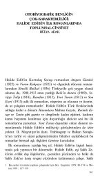
Fig. 1 „a,b… modal test setup <strong>and</strong> „c,d… frequency measurement<br />
setup<br />
the stable <strong>and</strong> unstable cutt<strong>in</strong>g zones, <strong>and</strong> absolute stability limit.<br />
In order to confirm the absolute stability limit prediction, a f<strong>in</strong>e<br />
variation <strong>of</strong> the depths is used. Also, the effect <strong>of</strong> the nose radius<br />
on the absolute stability limit is considered <strong>in</strong> the experiments by<br />
us<strong>in</strong>g <strong>in</strong>serts with different radii.<br />
A conventional manual lathe is used dur<strong>in</strong>g the experiments,<br />
which allows for specific sp<strong>in</strong>dle speeds, i.e., 700 rpm, 1000 rpm,<br />
1400 rpm, <strong>and</strong> 2000 rpm. A modal test setup is used to measure<br />
the transfer functions <strong>of</strong> the workpiece <strong>and</strong> the tool �Figs. 1�a� <strong>and</strong><br />
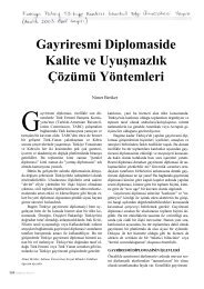
Fig. 2 Triangular <strong>in</strong>serts used dur<strong>in</strong>g tests with radii: „a…<br />
0.4 mm, „b… 0.8 mm, „c… 1.2 mm, <strong>and</strong> „d… the round <strong>in</strong>sert with a<br />
12.6 mm dia; „e… regular <strong>in</strong>sert seat <strong>and</strong> „f… ground <strong>in</strong>sert seat<br />
for desired rake <strong>and</strong> <strong>in</strong>cl<strong>in</strong>ation<br />
1�b��. The modal test setup consists <strong>of</strong> an impact hammer, an<br />
accelerometer, <strong>and</strong> a data acquisition system. The data are collected<br />
<strong>and</strong> analyzed by CutPro ® �8�. In addition, a sound frequency<br />
measurement setup was prepared <strong>in</strong> order to measure <strong>and</strong><br />
verify the chatter frequency �Figs. 1�c� <strong>and</strong> 1�d��. The setup consists<br />
<strong>of</strong> a microphone <strong>and</strong> a data acquisition setup. The data are<br />
collected <strong>and</strong> analyzed by LabView ® �9�. As a second check, the<br />
f<strong>in</strong>ished surface is observed by the naked eye for chatter marks <strong>in</strong><br />
order to verify the unstable cutt<strong>in</strong>g operation.<br />
In experiments, coated carbide triangular <strong>in</strong>serts with 0 deg<br />
rake angle are used. There are three <strong>in</strong>serts hav<strong>in</strong>g different nose<br />
radii, i.e., 0.4 mm, 0.8 mm, <strong>and</strong> 1.2 mm, as can be seen <strong>in</strong> Figs.<br />
Table 1 Parameters used <strong>in</strong> the verification <strong>of</strong> flexible tool<br />
turn<strong>in</strong>g chatter experiments<br />
Side edge cutt<strong>in</strong>g angle 10 deg<br />
Rake angle 5 deg<br />
Incl<strong>in</strong>ation angle 5 deg<br />
Insert nose radius 0.4 mm<br />
Cutt<strong>in</strong>g force coefficients, Kf 800 MPa<br />
Cutt<strong>in</strong>g force coefficients, K r<br />
128 MPa<br />
Natural frequency <strong>of</strong> the tool 1100 Hz<br />
Stifness <strong>of</strong> the tool 1.2�10 7 N/m<br />
Damp<strong>in</strong>g ratio 0.015<br />
734 / Vol. 129, AUGUST 2007 Transactions <strong>of</strong> the ASME<br />
Downloaded 16 Aug 2007 to 193.255.135.9. Redistribution subject to ASME license or copyright, see http://www.asme.org/terms/Terms_Use.cfm
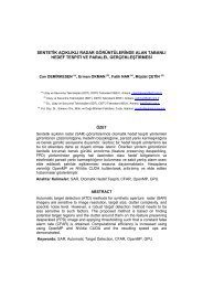
Fig. 3 „a… Transfer functions <strong>of</strong> the tool <strong>and</strong> the workpiece, „b… chatter frequency measurement result at 2000 rpm experiments,<br />
<strong>and</strong> „c… chatter test results for model verification <strong>and</strong> the surface f<strong>in</strong>ish <strong>of</strong> a stable versus unstable cut<br />
2�a�–2�c�, respectively. A round <strong>in</strong>sert �Fig. 2�d�� is also used <strong>in</strong><br />
order to verify the nose radius model. Also, a feed rate <strong>of</strong><br />
0.08 mm/rev was used for all tests.<br />
In order to avoid eccentricity <strong>and</strong> to cover a wider range <strong>of</strong><br />
angles <strong>in</strong> a practical manner, <strong>in</strong>sert seats with different angles<br />
were ground <strong>and</strong> used under the <strong>in</strong>serts dur<strong>in</strong>g the cutt<strong>in</strong>g tests<br />
�Figs. 2�e� <strong>and</strong> 2�f��. The side edge cutt<strong>in</strong>g angle <strong>in</strong> the turn<strong>in</strong>g<br />
experiments is set by rotat<strong>in</strong>g the tool holder from its clamped<br />
end. The workpiece material used dur<strong>in</strong>g the tests is a medium<br />
carbon steel �AISI 1040�, <strong>and</strong> an exist<strong>in</strong>g orthogonal database was<br />
used for the cutt<strong>in</strong>g force coefficients. The orthogonal database<br />
was generated by us<strong>in</strong>g orthogonal tube cutt<strong>in</strong>g tests. The cutt<strong>in</strong>g<br />
Journal <strong>of</strong> Manufactur<strong>in</strong>g Science <strong>and</strong> Eng<strong>in</strong>eer<strong>in</strong>g AUGUST 2007, Vol. 129 / 735<br />
Downloaded 16 Aug 2007 to 193.255.135.9. Redistribution subject to ASME license or copyright, see http://www.asme.org/terms/Terms_Use.cfm
Table 2 Parameters used <strong>in</strong> the verification <strong>of</strong> chatter tests<br />
with <strong>in</strong>serts hav<strong>in</strong>g nose radius<br />
Side edge cutt<strong>in</strong>g angle 10 deg<br />
Rake angle 5 deg<br />
Incl<strong>in</strong>ation angle 5 deg<br />
Sp<strong>in</strong>dle Speed 1000 rpm<br />
Cutt<strong>in</strong>g force coefficients, Kf 800 MPa<br />
Cutt<strong>in</strong>g force coefficients, K r<br />
forces <strong>and</strong> the cut chip thickness were measured dur<strong>in</strong>g the tests,<br />
which were conducted at different cutt<strong>in</strong>g speeds <strong>and</strong> feed rates <strong>in</strong><br />
order to identify the shear angle, the shear stress, <strong>and</strong> the friction<br />
angle �10–12�, us<strong>in</strong>g the orthogonal cutt<strong>in</strong>g model.<br />
4 Experimental Results<br />
128 MPa<br />
Natural frequency <strong>of</strong> the tool 1100 Hz<br />
Stifness <strong>of</strong> the tool 1.2�10 7 N/m<br />
Damp<strong>in</strong>g ratio 0.015<br />
In this section, the results obta<strong>in</strong>ed from the analytical predictions<br />
are compared to the experimental results. The experiments<br />
are designed to cover three different cases. The turn<strong>in</strong>g chatter<br />
experiments are divided <strong>in</strong>to two cases <strong>in</strong> order to verify the <strong>of</strong>fered<br />
stability model <strong>and</strong> to discuss the effects <strong>of</strong> <strong>in</strong>sert nose radius.<br />
In the first case, the tool is selected to be more flexible than<br />
the workpiece, <strong>and</strong> <strong>in</strong> the second case, workpiece is much more<br />
flexible than the tool. The first reason for this division is to cover<br />
various representative practical cases. Also, different effects <strong>of</strong> the<br />
nose radius shown <strong>in</strong> the first part <strong>of</strong> this study �1� will be verified.<br />
In the third case, bor<strong>in</strong>g chatter experiments are conducted us<strong>in</strong>g a<br />
highly flexible tool, which represents the most problematic case <strong>in</strong><br />
bor<strong>in</strong>g applications due to the long slender tools.<br />
Fig. 4 <strong>Chatter</strong> test results for nose radius effect demonstration<br />
<strong>and</strong> verification<br />
Table 3 Parameters used <strong>in</strong> the verification <strong>of</strong> round <strong>in</strong>sert for<br />
flexible tool turn<strong>in</strong>g experiments<br />
Rake angle 5 deg<br />
Incl<strong>in</strong>ation angle −5 deg<br />
Cutt<strong>in</strong>g force coefficients, Kf 800 MPa<br />
Cutt<strong>in</strong>g force coefficients, Kr Natural frequency <strong>of</strong> the tool<br />
128 MPa<br />
1162 Hz<br />
Stifness <strong>of</strong> the tool 9�106 N/m<br />
Damp<strong>in</strong>g ratio 0.011<br />
Fig. 5 <strong>Chatter</strong> test results for round nose <strong>in</strong>sert<br />
4.1 <strong>Chatter</strong> Experiments Case 1: Flexible Turn<strong>in</strong>g Tool<br />
<strong>and</strong> Rigid Workpiece. In the first experiment case, the turn<strong>in</strong>g<br />
chatter experiments are conducted <strong>in</strong> which the tool is more flexible<br />
than the workpiece. Inserts with different nose radii <strong>and</strong> round<br />
<strong>in</strong>sert tests are used <strong>in</strong> order to compare the predicted results. In<br />
the verification <strong>of</strong> the nose radius model <strong>in</strong> the second set, the aim<br />
is to verify the effect <strong>of</strong> the nose radius on the stability limit. In<br />
the f<strong>in</strong>al set the round nose <strong>in</strong>serts are used <strong>in</strong> chatter experiments,<br />
<strong>in</strong> order to verify the model for the <strong>in</strong>serts without straight edges.<br />
4.1.1 Turn<strong>in</strong>g With Flexible Tool: Verification <strong>of</strong> <strong>Stability</strong><br />
Limit. The first set <strong>of</strong> experiments is carried out <strong>in</strong> order to verify<br />
the proposed stability model given <strong>in</strong> �1�. The parameters that are<br />
used <strong>in</strong> the experiments <strong>and</strong> stability analysis are listed <strong>in</strong> Table 1.<br />
The other parameters can be found <strong>in</strong> Sec. 3. The comparison <strong>of</strong><br />
the workpiece <strong>and</strong> tool transfer functions is shown <strong>in</strong> Fig. 3�a�.<br />
The analytically calculated stability lobes along with the experimental<br />
results <strong>and</strong> an example <strong>of</strong> a surface f<strong>in</strong>ish after a stable <strong>and</strong><br />
unstable operation, for 2000 rpm, can be seen <strong>in</strong> Fig. 3�c�. Also,<br />
the chatter frequency measurements at 2000 rpm tests are shown<br />
<strong>in</strong> Fig. 3�b�. The experimental <strong>and</strong> the analytical results are <strong>in</strong><br />
close agreement.<br />
4.1.2 Turn<strong>in</strong>g With Flexible Tool: Demonstration <strong>and</strong> Verification<br />
<strong>of</strong> Nose Radius Effects. In the second set <strong>of</strong> experiments <strong>of</strong><br />
this case, the effect <strong>of</strong> the <strong>in</strong>sert nose radius on the stability limit<br />
is demonstrated <strong>and</strong> verified for a case where the tool is more<br />
flexible than the workpiece. The cutt<strong>in</strong>g conditions <strong>and</strong> angles that<br />
are used dur<strong>in</strong>g chatter tests <strong>and</strong> stability analysis are listed <strong>in</strong><br />
Table 2. The other parameters can be found <strong>in</strong> Sec. 3.<br />
The results can be seen <strong>in</strong> Fig. 4. The <strong>in</strong>sert nose radius contributes<br />
to the dynamic system similar to the effect <strong>of</strong> the side<br />
edge cutt<strong>in</strong>g angle. Therefore, as the <strong>in</strong>sert nose radius <strong>in</strong>creases<br />
the effect <strong>of</strong> the dynamics <strong>in</strong> the depth <strong>of</strong> cut direction <strong>in</strong>creases<br />
Table 4 Parameters used <strong>in</strong> the verification <strong>of</strong> flexible workpiece<br />
turn<strong>in</strong>g chatter experiments<br />
Side edge cutt<strong>in</strong>g angle 30 deg<br />
Rake angle 5 deg<br />
Incl<strong>in</strong>ation angle 5 deg<br />
Insert nose radius 0.4 mm<br />
Cutt<strong>in</strong>g force coefficients, Kf 632 MPa<br />
Cutt<strong>in</strong>g force coefficients, K r<br />
44 MPa<br />
Natural frequency <strong>of</strong> the workpiece 770 Hz<br />
Stifness <strong>of</strong> the workpiece 6.6�10 6 N/m<br />
Damp<strong>in</strong>g ratio 0.025<br />
736 / Vol. 129, AUGUST 2007 Transactions <strong>of</strong> the ASME<br />
Downloaded 16 Aug 2007 to 193.255.135.9. Redistribution subject to ASME license or copyright, see http://www.asme.org/terms/Terms_Use.cfm
Fig. 6 „a… Transfer functions <strong>of</strong> the tool <strong>and</strong> the workpiece, „b… chatter sound measurement results for 1400 rpm<br />
tests, <strong>and</strong> „c… chatter test results for model verification <strong>and</strong> the surface f<strong>in</strong>ish <strong>of</strong> a stable versus unstable cut<br />
as well. So, the <strong>in</strong>crease <strong>in</strong> the <strong>in</strong>sert nose radius <strong>in</strong>creases the<br />
effect <strong>of</strong> the workpiece dynamics on the cutt<strong>in</strong>g system. S<strong>in</strong>ce the<br />
tool is more flexible than the workpiece, this makes the system<br />
more rigid, <strong>in</strong>creas<strong>in</strong>g the stability limit. This behavior is also<br />
observed <strong>in</strong> the experimental results, <strong>and</strong> a high level <strong>of</strong> agreement<br />
with the analytical predictions is obta<strong>in</strong>ed.<br />
4.1.3 Turn<strong>in</strong>g With Flexible Tool: Round Insert Experiments.<br />
In this first case <strong>of</strong> the last set <strong>of</strong> experiments, the <strong>in</strong>sert nose<br />
radius model is verified by a round <strong>in</strong>sert where the tool is more<br />
flexible than the workpiece. The cutt<strong>in</strong>g conditions <strong>and</strong> angles that<br />
are used dur<strong>in</strong>g chatter tests <strong>and</strong> stability predictions are listed <strong>in</strong><br />
Table 3. The other parameters can be found <strong>in</strong> Sec. 3.<br />
Journal <strong>of</strong> Manufactur<strong>in</strong>g Science <strong>and</strong> Eng<strong>in</strong>eer<strong>in</strong>g AUGUST 2007, Vol. 129 / 737<br />
Downloaded 16 Aug 2007 to 193.255.135.9. Redistribution subject to ASME license or copyright, see http://www.asme.org/terms/Terms_Use.cfm
Table 5 Parameters used <strong>in</strong> the verification <strong>of</strong> chatter tests<br />
with <strong>in</strong>serts hav<strong>in</strong>g nose radius<br />
Side edge cutt<strong>in</strong>g angle 25 deg<br />
Rake angle 5 deg<br />
Incl<strong>in</strong>ation angle 5 deg<br />
Sp<strong>in</strong>dle Speed 1400 rpm<br />
Cutt<strong>in</strong>g force coefficients, Kf 632 MPa<br />
Cutt<strong>in</strong>g force coefficients, K r<br />
44 MPa<br />
Natural frequency <strong>of</strong> the workpiece 707 Hz<br />
Stifness <strong>of</strong> the workpiece 6.5�10 6 N/m<br />
Damp<strong>in</strong>g ratio 0.023<br />
The comparison <strong>of</strong> experimental <strong>and</strong> analytical results can be<br />
seen <strong>in</strong> Fig. 5. Reasonable agreement is found between the analytical<br />
<strong>and</strong> experimental results.<br />
4.2 <strong>Chatter</strong> Experiments Case 2: Flexible Workpiece <strong>and</strong><br />
Rigid Turn<strong>in</strong>g Tool. In the second case, the turn<strong>in</strong>g chatter experiments<br />
are conducted where the workpiece is clamped <strong>in</strong> such<br />
a way that it is more flexible than the tool. The nose radius is<br />
varied <strong>in</strong> the tests <strong>in</strong> order to compare to the predicted results.<br />
4.2.1 Turn<strong>in</strong>g <strong>of</strong> a Flexible Workpiece: Verification <strong>of</strong> <strong>Stability</strong><br />
Limit. This first set <strong>of</strong> experiments is conducted <strong>in</strong> order to verify<br />
the proposed stability model �1� for the case where the workpiece<br />
is more flexible than the tool. The parameters that are used specifically<br />
for the verification <strong>of</strong> flexible workpiece turn<strong>in</strong>g chatter<br />
experiments <strong>and</strong> stability predictions are listed <strong>in</strong> Table 4. The<br />
other parameters can be found <strong>in</strong> Sec. 3. The workpiece diameter<br />
<strong>and</strong> length were 39 mm <strong>and</strong> 75 mm, respectively. Moreover, the<br />
comparison between the tool <strong>and</strong> workpiece transfer functions is<br />
shown <strong>in</strong> Fig. 6�a�.<br />
The predicted stability lobes <strong>and</strong> experimental results are given<br />
<strong>in</strong> Fig. 6�c�, where a sample f<strong>in</strong>ished surface after a stable <strong>and</strong><br />
unstable operation can be seen. Also, the measured chatter sound<br />
for 1400 rpm is given <strong>in</strong> Fig. 6�b�. The difference <strong>in</strong> 700 rpm <strong>and</strong><br />
1000 rpm tests are caused by the process damp<strong>in</strong>g due to the low<br />
cutt<strong>in</strong>g speed used �13,14�. Reasonable agreement is observed between<br />
the experimental <strong>and</strong> analytical results.<br />
4.2.2 Turn<strong>in</strong>g <strong>of</strong> a Flexible Workpiece: Demonstration <strong>and</strong><br />
Verification <strong>of</strong> Nose Radius Effects. In the second set <strong>of</strong> experiments<br />
<strong>of</strong> this case, the effect <strong>of</strong> the <strong>in</strong>sert nose radius on the<br />
stability limit is demonstrated <strong>and</strong> verified with an experiment<br />
where the workpiece is more flexible than the tool. The cutt<strong>in</strong>g<br />
conditions <strong>and</strong> angles used dur<strong>in</strong>g the chatter tests <strong>and</strong> the stability<br />
predictions are listed <strong>in</strong> Table 5. The sp<strong>in</strong>dle speed used dur<strong>in</strong>g<br />
experiments is 1400 rpm. The other parameters can be found <strong>in</strong><br />
Sec. 3. As <strong>in</strong> the previous tests, the workpiece diameter was<br />
39 mm <strong>and</strong> the length was 75 mm.<br />
The analytically predicted stability diagram along with the experimental<br />
results is given <strong>in</strong> Fig. 7. As the <strong>in</strong>sert nose radius<br />
<strong>in</strong>creases, the effect <strong>of</strong> workpiece dynamics �which is more flexible�<br />
on the chip thickness also <strong>in</strong>creases. Therefore, the dynamic<br />
system becomes more flexible result<strong>in</strong>g <strong>in</strong> a decrease <strong>in</strong> the absolute<br />
stability limit. Another conclusion, which was also shown <strong>in</strong><br />
the first part <strong>of</strong> this paper �1� by the simulations, is that the effect<br />
<strong>of</strong> the <strong>in</strong>sert nose radius on the stability is more pronounced <strong>in</strong><br />
flexible workpiece case than <strong>in</strong> flexible tool case �see Figs. 4 <strong>and</strong><br />
7�. In order to expla<strong>in</strong> this situation, first, it should be noted that<br />
when the side edge cutt<strong>in</strong>g angle <strong>and</strong> <strong>in</strong>sert nose radius are zero,<br />
the system dynamics are only controlled by the transfer function<br />
<strong>of</strong> the tool <strong>in</strong> the feed direction. The workpiece dynamics can only<br />
affect the dynamics <strong>of</strong> the cutt<strong>in</strong>g system if there is a side edge<br />
cutt<strong>in</strong>g angle, or the <strong>in</strong>sert has a nose radius. In that case, if the<br />
workpiece is more flexible than the tool, the flexibility <strong>in</strong>troduced<br />
to the dynamic system reduces the stability limit drastically. On<br />
the other h<strong>and</strong>, if the workpiece is more rigid than the tool, then<br />
Fig. 7 <strong>Chatter</strong> test results for the flexible workpiece case with<br />
<strong>in</strong>serts hav<strong>in</strong>g different nose radii<br />
the dynamic rigidity <strong>of</strong> the system may <strong>in</strong>crease, <strong>and</strong> the level <strong>of</strong><br />
<strong>in</strong>crease depends on the relative rigidities <strong>of</strong> the tool <strong>and</strong> the<br />
workpiece as well as values <strong>of</strong> the side cutt<strong>in</strong>g edge angle or nose<br />
radius. Compar<strong>in</strong>g the experimental results <strong>and</strong> the analytical predictions<br />
presented <strong>in</strong> this section, a close agreement can be concluded.<br />
4.3 <strong>Chatter</strong> Experiment Case 3: Bor<strong>in</strong>g Experiments. In<br />
this last case, bor<strong>in</strong>g chatter experiments were conducted where<br />
the tool was clamped <strong>in</strong> such a way that it was much more flexible<br />
than the workpiece represent<strong>in</strong>g the common problem <strong>in</strong> practical<br />
bor<strong>in</strong>g applications. The nose radius is varied <strong>in</strong> order to verify<br />
the predicted results. The cutt<strong>in</strong>g conditions <strong>and</strong> angles used <strong>in</strong> the<br />
chatter tests <strong>and</strong> stability analysis are listed <strong>in</strong> Table 6. The other<br />
parameters can be found <strong>in</strong> Sec. 3.<br />
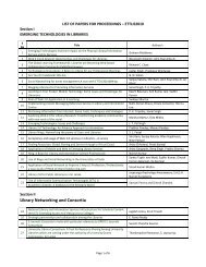
The analytically predicted absolute stability limits <strong>and</strong> the experimental<br />
results for <strong>in</strong>serts with 0.4 mm, 0.8 mm, <strong>and</strong> 1.2 mm<br />
nose radius are shown <strong>in</strong> Fig. 8. The analytical stability limit for<br />
the <strong>in</strong>sert with 0.4 mm nose radius is �8 mm. However, dur<strong>in</strong>g<br />
the tests, a maximum depth <strong>of</strong> cut <strong>of</strong> 1 mm was imposed <strong>in</strong> order<br />
to avoid high cutt<strong>in</strong>g forces, <strong>and</strong> consequently, high deformation<br />
that the slender bor<strong>in</strong>g bar will encounter. The results are also<br />
shown for the other two <strong>in</strong>serts with 0.8 mm <strong>and</strong> 1.2 mm nose<br />
radii. It should also be noted here that the observed trend <strong>of</strong> the<br />
absolute stability limit with the vary<strong>in</strong>g <strong>in</strong>sert nose radius is expected.<br />
In case <strong>of</strong> bor<strong>in</strong>g, an <strong>in</strong>crease <strong>in</strong> the nose radius <strong>in</strong>creases<br />
the effect <strong>of</strong> the tool’s flexibility on the dynamic cutt<strong>in</strong>g system,<br />
which reduces the absolute stability limit. The drastic change <strong>in</strong><br />
the absolute stability limit is due to the sudden <strong>in</strong>crease <strong>of</strong> the<br />
flexible tool’s effect on the rigid dynamic system, which was also<br />
observed <strong>in</strong> Sec. 4.2.2 for the flexible workpiece tests.<br />
Table 6 Parameters used <strong>in</strong> the verification <strong>of</strong> bor<strong>in</strong>g chatter<br />
experiments<br />
Side edge cutt<strong>in</strong>g angle 0 deg<br />
Rake angle 0 deg<br />
Incl<strong>in</strong>ation angle 0 deg<br />
Sp<strong>in</strong>dle speed 1400 rpm<br />
Cutt<strong>in</strong>g force coefficients, Kf Natural frequency <strong>of</strong> the tool<br />
700 MPa<br />
3690 Hz<br />
Stifness <strong>of</strong> the tool 2.3�107 N/m<br />
Damp<strong>in</strong>g ratio 0.012<br />
738 / Vol. 129, AUGUST 2007 Transactions <strong>of</strong> the ASME<br />
Downloaded 16 Aug 2007 to 193.255.135.9. Redistribution subject to ASME license or copyright, see http://www.asme.org/terms/Terms_Use.cfm
5 Conclusions<br />
Three cases <strong>of</strong> chatter experiments are conducted <strong>in</strong> order to<br />
verify the analytical stability models presented <strong>in</strong> �1�. In general,<br />
the agreement between the analytical predictions <strong>and</strong> the experimental<br />
results are found to be satisfactory. The ma<strong>in</strong> conclusions<br />
<strong>of</strong> the current study can be summarized as follows:<br />
• The effect <strong>of</strong> <strong>in</strong>sert nose radius on the stability limit is critical<br />
when the absolute stability limit <strong>of</strong> the system is comparable<br />
to the nose radius, <strong>and</strong> this should be taken <strong>in</strong>to<br />
account dur<strong>in</strong>g predictions.<br />
• The effect <strong>of</strong> the <strong>in</strong>sert nose radius on the stability limit for<br />
turn<strong>in</strong>g with a flexible tool, turn<strong>in</strong>g <strong>of</strong> a flexible workpiece<br />
<strong>and</strong> bor<strong>in</strong>g operations are different which is verified, <strong>and</strong> the<br />
observed behavior is as expected from the analytical predictions.<br />
• It is found that us<strong>in</strong>g <strong>in</strong>serts with a bigger <strong>in</strong>sert nose radius<br />
drastically reduces the stability limit <strong>in</strong> the turn<strong>in</strong>g <strong>of</strong> flexible<br />
workpieces <strong>and</strong> <strong>in</strong> bor<strong>in</strong>g operations whereas the opposite<br />
is true for the turn<strong>in</strong>g applications with a flexible tool.<br />
References<br />
Fig. 8 <strong>Chatter</strong> test results for bor<strong>in</strong>g model verification <strong>and</strong> the surface f<strong>in</strong>ish <strong>of</strong> a stable versus unstable cut<br />
�1� Ozlu, E., <strong>and</strong> Budak, E., 2006, “<strong>Analytical</strong> <strong>Model<strong>in</strong>g</strong> <strong>of</strong> <strong>Chatter</strong> <strong>Stability</strong> <strong>in</strong><br />
Turn<strong>in</strong>g <strong>and</strong> Bor<strong>in</strong>g Operations—Part I: Model Development,” ASME J.<br />
Manuf. Sci. Eng., 129�4�, pp. 726–732.<br />
�2� Tlusty, J., <strong>and</strong> Polacek, M., 1963, “The <strong>Stability</strong> <strong>of</strong> Mach<strong>in</strong>e Tools Aga<strong>in</strong>st<br />
Self Excited Vibrations <strong>in</strong> Mach<strong>in</strong><strong>in</strong>g,” Proceed<strong>in</strong>gs <strong>of</strong> the International Research<br />
<strong>in</strong> Production Eng<strong>in</strong>eer<strong>in</strong>g Conference, Pittsburgh, PA, ASME, New<br />
York, pp. 465–474.<br />
�3� Tobias, S. A., <strong>and</strong> Fishwick, W., 1958, “The <strong>Chatter</strong> <strong>of</strong> Lathe Tools Under<br />
Orthogonal Cutt<strong>in</strong>g Conditions,” Transactions <strong>of</strong> ASME, 80, pp. 1079–1088.<br />
�4� Rao, C. B., <strong>and</strong> Sh<strong>in</strong>, Y. C., 1999, “A Comprehensive Dynamic Cutt<strong>in</strong>g Force<br />
Model for <strong>Chatter</strong> Prediction <strong>in</strong> Turn<strong>in</strong>g,” Int. J. Mach. Tools Manuf., 39, pp.<br />
1631–1654.<br />
�5� Clancy, B. E., <strong>and</strong> Sh<strong>in</strong>, Y. C., 2002, “A Comprehensive <strong>Chatter</strong> Prediction<br />
Model for Face Turn<strong>in</strong>g Operation Includ<strong>in</strong>g Tool Wear Effect,” Int. J. Mach.<br />
Tools Manuf., 42, pp. 1035–1044.<br />
�6� Lazoglu, I., Atabey, F., <strong>and</strong> Alt<strong>in</strong>tas, Y., 2002, “Dynamic <strong>of</strong> Bor<strong>in</strong>g Processes:<br />
Part III—Time Doma<strong>in</strong>,” Int. J. Mach. Tools Manuf., 42, pp. 1567–1576.<br />
�7� Armarego, E. J. A., <strong>and</strong> Brown, R. H., 1969, The Mach<strong>in</strong><strong>in</strong>g <strong>of</strong> Metals,<br />
Prentice-Hall, Englewood Cliffs, NJ.<br />
�8� CutPro ® Web site: http://www.mal<strong>in</strong>c.com<br />
�9� LabView ® Web site: http://www.labview.com<br />
�10� Armarego, E. J. A., <strong>and</strong> Whitfield, R. C., 1985, “Computer Based <strong>Model<strong>in</strong>g</strong> <strong>of</strong><br />
Popular Mach<strong>in</strong><strong>in</strong>g Operations for Force <strong>and</strong> Power Predictions,” CIRP Ann.,<br />
34, pp. 65–69.<br />
�11� Budak, E., Alt<strong>in</strong>tas, Y., <strong>and</strong> Armarego, E. J. A., 1996, “Prediction <strong>of</strong> Mill<strong>in</strong>g<br />
Force Coefficients From Orthogonal Cutt<strong>in</strong>g Data,” ASME J. Manuf. Sci.<br />
Eng., 118, pp. 216–224.<br />
�12� Alt<strong>in</strong>tas, Y., 2000, Manufactur<strong>in</strong>g Automation, Cambridge University Press,<br />
Cambridge, Engl<strong>and</strong>.<br />
�13� Tlusty, J., 1978, “Analysis <strong>of</strong> the State <strong>of</strong> Research <strong>in</strong> Cutt<strong>in</strong>g Dynamics,”<br />
CIRP Ann., 27�2�, pp. 583–589.<br />
�14� Lee, B. Y., Tarng, Y. S., <strong>and</strong> Ma, S. C., 1995, “<strong>Model<strong>in</strong>g</strong> <strong>of</strong> The Process<br />
Damp<strong>in</strong>g Force <strong>in</strong> <strong>Chatter</strong> Vibrations,” Int. J. Mach. Tools Manuf., 35�7�, pp.<br />
951–962.<br />
Journal <strong>of</strong> Manufactur<strong>in</strong>g Science <strong>and</strong> Eng<strong>in</strong>eer<strong>in</strong>g AUGUST 2007, Vol. 129 / 739<br />
Downloaded 16 Aug 2007 to 193.255.135.9. Redistribution subject to ASME license or copyright, see http://www.asme.org/terms/Terms_Use.cfm