Analytical Modeling of Chatter Stability in Turning and Boring ...
Analytical Modeling of Chatter Stability in Turning and Boring ...
Analytical Modeling of Chatter Stability in Turning and Boring ...

Create successful ePaper yourself
Turn your PDF publications into a flip-book with our unique Google optimized e-Paper software.
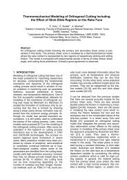
Fig. 1 „a,b… modal test setup <strong>and</strong> „c,d… frequency measurement<br />
setup<br />
the stable <strong>and</strong> unstable cutt<strong>in</strong>g zones, <strong>and</strong> absolute stability limit.<br />
In order to confirm the absolute stability limit prediction, a f<strong>in</strong>e<br />
variation <strong>of</strong> the depths is used. Also, the effect <strong>of</strong> the nose radius<br />
on the absolute stability limit is considered <strong>in</strong> the experiments by<br />
us<strong>in</strong>g <strong>in</strong>serts with different radii.<br />
A conventional manual lathe is used dur<strong>in</strong>g the experiments,<br />
which allows for specific sp<strong>in</strong>dle speeds, i.e., 700 rpm, 1000 rpm,<br />
1400 rpm, <strong>and</strong> 2000 rpm. A modal test setup is used to measure<br />
the transfer functions <strong>of</strong> the workpiece <strong>and</strong> the tool �Figs. 1�a� <strong>and</strong><br />
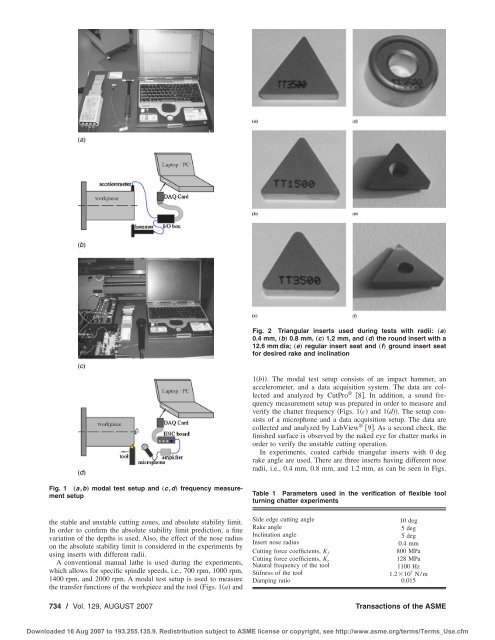
Fig. 2 Triangular <strong>in</strong>serts used dur<strong>in</strong>g tests with radii: „a…<br />
0.4 mm, „b… 0.8 mm, „c… 1.2 mm, <strong>and</strong> „d… the round <strong>in</strong>sert with a<br />
12.6 mm dia; „e… regular <strong>in</strong>sert seat <strong>and</strong> „f… ground <strong>in</strong>sert seat<br />
for desired rake <strong>and</strong> <strong>in</strong>cl<strong>in</strong>ation<br />
1�b��. The modal test setup consists <strong>of</strong> an impact hammer, an<br />
accelerometer, <strong>and</strong> a data acquisition system. The data are collected<br />
<strong>and</strong> analyzed by CutPro ® �8�. In addition, a sound frequency<br />
measurement setup was prepared <strong>in</strong> order to measure <strong>and</strong><br />
verify the chatter frequency �Figs. 1�c� <strong>and</strong> 1�d��. The setup consists<br />
<strong>of</strong> a microphone <strong>and</strong> a data acquisition setup. The data are<br />
collected <strong>and</strong> analyzed by LabView ® �9�. As a second check, the<br />
f<strong>in</strong>ished surface is observed by the naked eye for chatter marks <strong>in</strong><br />
order to verify the unstable cutt<strong>in</strong>g operation.<br />
In experiments, coated carbide triangular <strong>in</strong>serts with 0 deg<br />
rake angle are used. There are three <strong>in</strong>serts hav<strong>in</strong>g different nose<br />
radii, i.e., 0.4 mm, 0.8 mm, <strong>and</strong> 1.2 mm, as can be seen <strong>in</strong> Figs.<br />
Table 1 Parameters used <strong>in</strong> the verification <strong>of</strong> flexible tool<br />
turn<strong>in</strong>g chatter experiments<br />
Side edge cutt<strong>in</strong>g angle 10 deg<br />
Rake angle 5 deg<br />
Incl<strong>in</strong>ation angle 5 deg<br />
Insert nose radius 0.4 mm<br />
Cutt<strong>in</strong>g force coefficients, Kf 800 MPa<br />
Cutt<strong>in</strong>g force coefficients, K r<br />
128 MPa<br />
Natural frequency <strong>of</strong> the tool 1100 Hz<br />
Stifness <strong>of</strong> the tool 1.2�10 7 N/m<br />
Damp<strong>in</strong>g ratio 0.015<br />
734 / Vol. 129, AUGUST 2007 Transactions <strong>of</strong> the ASME<br />
Downloaded 16 Aug 2007 to 193.255.135.9. Redistribution subject to ASME license or copyright, see http://www.asme.org/terms/Terms_Use.cfm