t - Sabanci University Research Database
t - Sabanci University Research Database
t - Sabanci University Research Database

Create successful ePaper yourself
Turn your PDF publications into a flip-book with our unique Google optimized e-Paper software.
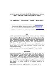
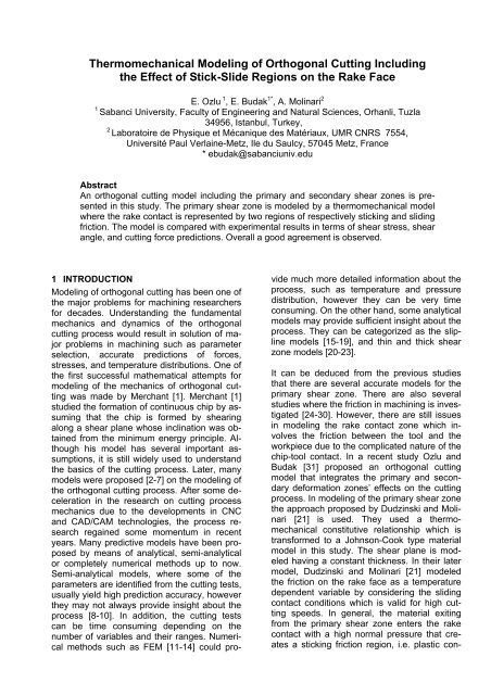
Thermomechanical Modeling of Orthogonal Cutting Including<br />
the Effect of Stick-Slide Regions on the Rake Face<br />
E. Ozlu 1 , E. Budak 1* , A. Molinari 2<br />
1 <strong>Sabanci</strong> <strong>University</strong>, Faculty of Engineering and Natural Sciences, Orhanli, Tuzla<br />
34956, Istanbul, Turkey,<br />
2 Laboratoire de Physique et Mécanique des Matériaux, UMR CNRS 7554,<br />
Université Paul Verlaine-Metz, Ile du Saulcy, 57045 Metz, France<br />
* ebudak@sabanciuniv.edu<br />
Abstract<br />
An orthogonal cutting model including the primary and secondary shear zones is presented<br />
in this study. The primary shear zone is modeled by a thermomechanical model<br />
where the rake contact is represented by two regions of respectively sticking and sliding<br />
friction. The model is compared with experimental results in terms of shear stress, shear<br />
angle, and cutting force predictions. Overall a good agreement is observed.<br />
1 INTRODUCTION<br />
Modeling of orthogonal cutting has been one of<br />
the major problems for machining researchers<br />
for decades. Understanding the fundamental<br />
mechanics and dynamics of the orthogonal<br />
cutting process would result in solution of major<br />
problems in machining such as parameter<br />
selection, accurate predictions of forces,<br />
stresses, and temperature distributions. One of<br />
the first successful mathematical attempts for<br />
modeling of the mechanics of orthogonal cutting<br />
was made by Merchant [1]. Merchant [1]<br />
studied the formation of continuous chip by assuming<br />
that the chip is formed by shearing<br />
along a shear plane whose inclination was obtained<br />
from the minimum energy principle. Although<br />
his model has several important assumptions,<br />
it is still widely used to understand<br />
the basics of the cutting process. Later, many<br />
models were proposed [2-7] on the modeling of<br />
the orthogonal cutting process. After some deceleration<br />
in the research on cutting process<br />
mechanics due to the developments in CNC<br />
and CAD/CAM technologies, the process research<br />
regained some momentum in recent<br />
years. Many predictive models have been proposed<br />
by means of analytical, semi-analytical<br />
or completely numerical methods up to now.<br />
Semi-analytical models, where some of the<br />
parameters are identified from the cutting tests,<br />
usually yield high prediction accuracy, however<br />
they may not always provide insight about the<br />
process [8-10]. In addition, the cutting tests<br />
can be time consuming depending on the<br />
number of variables and their ranges. Numerical<br />
methods such as FEM [11-14] could pro-<br />
vide much more detailed information about the<br />
process, such as temperature and pressure<br />
distribution, however they can be very time<br />
consuming. On the other hand, some analytical<br />
models may provide sufficient insight about the<br />
process. They can be categorized as the slipline<br />
models [15-19], and thin and thick shear<br />
zone models [20-23].<br />
It can be deduced from the previous studies<br />
that there are several accurate models for the<br />
primary shear zone. There are also several<br />
studies where the friction in machining is investigated<br />
[24-30]. However, there are still issues<br />
in modeling the rake contact zone which involves<br />
the friction between the tool and the<br />
workpiece due to the complicated nature of the<br />
chip-tool contact. In a recent study Ozlu and<br />
Budak [31] proposed an orthogonal cutting<br />
model that integrates the primary and secondary<br />
deformation zones’ effects on the cutting<br />
process. In modeling of the primary shear zone<br />
the approach proposed by Dudzinski and Molinari<br />
[21] is used. They used a thermomechanical<br />
constitutive relationship which is<br />
transformed to a Johnson-Cook type material<br />
model in this study. The shear plane is modeled<br />
having a constant thickness. In their later<br />
model, Dudzinski and Molinari [21] modeled<br />
the friction on the rake face as a temperature<br />
dependent variable by considering the sliding<br />
contact conditions which is valid for high cutting<br />
speeds. In general, the material exiting<br />
from the primary shear zone enters the rake<br />
contact with a high normal pressure that creates<br />
a sticking friction region, i.e. plastic con-
tact, between the tool and the material. After a<br />
short distance, the contact state changes to<br />
sliding, i.e. elastic, due to the decreasing normal<br />
pressure which can be represented by<br />
Coulomb friction. Ozlu and Budak [31] considered<br />
this by modeling the rake face contact<br />
using dual zones.<br />
In this study, an orthogonal cutting model is<br />
presented for the prediction of cutting forces.<br />
The model uses thermomechanical model for<br />
the primary zone and considers dual contact<br />
zone for the rake contact. The minimum energy<br />
approach is used for the shear angle prediction<br />
and the material model constants are<br />
calibrated directly from the cutting tests. The<br />
friction and material constants can be obtained<br />
from orthogonal cutting tests. Orthogonal tube<br />
cutting tests are conducted for the calibration.<br />
After calibration, the model can be used for<br />
different machining operations using the same<br />
tool and workpiece material. The outputs of the<br />
proposed model are the shear angle, shear<br />
stress in the shear plane, cutting forces, the<br />
stress distributions on the rake face, sliding<br />
friction coefficient, and the length of the sticking<br />
and sliding zones. Although the model is<br />
still under development, the final aim of the<br />
model is to develop a cutting process model<br />
which needs minimum amount of calibration<br />
tests.<br />
The paper is organized as follows. The proposed<br />
mathematical formulation is presented in<br />
the next section. In section 3 the results obtained<br />
from the experimental results are presented<br />
and discussed.<br />
2 PROCESS MODEL<br />
In this section, the model for the orthogonal cutting<br />
process is presented together with the<br />
identification of the coefficient of friction between<br />
the tool and the workpiece materials.<br />
Firstly, the basic formulations regarding the<br />
primary and secondary shear zones are given,<br />
although the detailed derivation can be found in<br />
[31]. Then the tube cutting test setup is presented<br />
from where the coefficient of friction is<br />
identified. Finally different solution procedures<br />
are introduced in order to obtain the shear<br />
stress, cutting forces, stress distributions on the<br />
rake face and the length of the contact zones.<br />
2.1 Modeling of the Primary and Secondary<br />
Shear Zones<br />
The proposed model in this study includes the<br />
modeling of the primary and secondary shear<br />
zones in the orthogonal cutting process. The<br />
primary shear zone model is adapted from<br />
Dudzinski and Molinari [21] and the contact at<br />
the rake face is modeled by dual zone approach.<br />
Although the detailed mathematical<br />
model can be found at [21] and [22], it is presented<br />
here briefly. It should be mentioned<br />
here that the calculation of the shear angle is<br />
also included in this study which is one step<br />
ahead from the aforementioned study [31]. The<br />
main assumption in modeling the primary shear<br />
zone is that the shear plane has a thickness of<br />
h, and no plastic deformation occurs before and<br />
after the shear plane up to the sticking region at<br />
the rake face. The material behavior is represented<br />
with the Johnson-Cook constitutive<br />
model as follows:<br />
( ) ⎤ ⎡<br />
⎡<br />
n ⎤⎡<br />
m<br />
⎛ ⎞<br />
⎤<br />
1 ⎛ ⎞<br />
v<br />
⎢<br />
γ �<br />
⎥⎢<br />
γ<br />
⎥<br />
⎢⎣ ⎥⎦<br />
−<br />
τ = A + B +<br />
⎢ ⎜<br />
⎟<br />
⎢ ⎜<br />
⎟ 1 ln 1 T (1<br />
3 ⎥<br />
⎥<br />
⎣<br />
⎝ 3 ⎠<br />
⎦⎣<br />
⎝ � γ 0 ⎠<br />
⎦<br />
)<br />
where γ is the shear strain, γ�is the shear strain<br />
rate, γ� 0 is the reference shear strain rate, A, B,<br />
n, m, and v are material constants, and T = (T-<br />
Tr)/(Tm-Tr) where T is the absolute temperature,<br />
Tr is the reference temperature, Tm is the melting<br />
temperature. The material entering the primary<br />
shear zone sustains a shear stress of τ0.<br />
When it leaves the primary shear zone the<br />
shear stress has evolved to the value τ1 which<br />
is different from τ0 when inertia effects are important.<br />
Assuming a constant thickness of the<br />
shear zone and a uniform pressure distribution,<br />
τ0 can be iteratively calculated as proposed by<br />
[22]. Also from the equations of motion for a<br />
steady state solution and continuous type chip<br />
the shear stress at the exit of the shear plane is<br />
calculated as follows:<br />
2 ( φ)<br />
γ1<br />
0<br />
τ = V +<br />
(2)<br />
1 ρ sin τ<br />
where V is the cutting speed, φ is the shear angle<br />
and γ1 is the strain due to the plastic deformation<br />
at the shear plane.<br />
On the other hand, contact between the material<br />
and the workpiece at the rake face is modeled<br />
by a dual zone approach. This contact is<br />
divided into the sticking and sliding friction regions<br />
which was originally proposed by Zorev<br />
[3]. In the first region, the contact condition is<br />
plastic due to the high normal pressure exerted<br />
on the tool, whereas in the second region the<br />
contact is elastic which can be represented by<br />
sliding friction. Zorev [3], and later others [32-<br />
34], proposed shear and normal stress distribution<br />
on the rake face as shown in Figure 1.a.
However it is well known and also proved by<br />
friction tests [35] that the Coulomb friction coefficient<br />
cannot exceed 1.0 between metallic materials<br />
unless some kind of oxide formation or<br />
chemical reaction occurs [26,36]. Therefore, as<br />
shown by split tool cutting tests and mathematical<br />
analyses [18,28,35,37-39] the distributions<br />
of the shear and normal stresses on the<br />
rake face are considered to be as shown in Figure<br />
1.b. which is used for the model in this<br />
study. In order to model the normal pressure on<br />
the rake face mathematically, the following distribution<br />
is selected [31]:<br />
P<br />
( x )<br />
ζ<br />
⎛ x ⎞<br />
= P0<br />
⎜ ⎟<br />
⎜<br />
1−<br />
(3)<br />
⎟<br />
⎝ � c ⎠<br />
where ℓc is the contact length (see Figure 2), x<br />
is the distance on the rake face from the tool<br />
tip, and ζ is the exponential constant which represents<br />
the distribution of the pressure, and is<br />
selected as 3 in the current study.<br />
(a)<br />
stress distribution<br />
stress distribution<br />
distance from tool tip<br />
Normal Stress Shear Stress<br />
(b)<br />
distance from tool tip<br />
Normal Stress Shear Stress<br />
Figure 1: Stress distributions on the rake face<br />
by two different approaches, where the sliding<br />
friction coefficient is (a) higher, and (b) smaller<br />
than 1.<br />
It can be observed from Figure 1.b, that the<br />
shear stress on the rake face is equal to the<br />
shear yield stress of the material (τ1) along the<br />
sticking region with length ℓp. In addition, the<br />
shear stress in the sliding region is equal to the<br />
product of sliding friction coefficient (μ) and the<br />
normal stress (P), according to the Coulomb<br />
friction law. The shear stress reduces to zero at<br />
the end of the contact zone. Therefore, the<br />
mathematical representation of the shear stress<br />
distribution on the rake face can be defined as<br />
follows:<br />
τ = τ1<br />
x ≤ � p<br />
(4)<br />
τ = μP<br />
� p ≤ x ≤ �c<br />
Moreover the shear stress distribution along the<br />
sliding friction region can be defined as follows:<br />
τ<br />
( x )<br />
ζ<br />
⎛ x − � p ⎞<br />
= τ ⎜ ⎟<br />
⎜<br />
1 − � 1 ⎟ p x ≤ �c<br />
⎝ � e ⎠<br />
≤ (5)<br />
where ℓe is the length of the sliding region (see<br />
Figure2).<br />
h1<br />
θ<br />
Ff<br />
B<br />
Fn<br />
A<br />
ℓp<br />
Ft<br />
R<br />
α N<br />
Np<br />
Fp<br />
ℓc<br />
Fs<br />
ℓe<br />
F<br />
Ne<br />
α<br />
B<br />
Fe<br />
C<br />
TOOL<br />
Figure 2: The Merchant’s Circle and the schematic<br />
representation of the forces acting on the<br />
rake face.<br />
P0 in equation (3) which is needed to calculate<br />
most of the parameters can be obtained from<br />
the force equilibrium at the shear plane and the<br />
rake face as follows [22, 31]:<br />
P0<br />
h<br />
= τ1<br />
�<br />
1<br />
( ζ + 1)<br />
c<br />
cos λ<br />
sinφ<br />
cos<br />
( φ + λ − α )<br />
C<br />
γ<br />
(6)<br />
where h1 is the uncut chip thickness, λ is the<br />
friction angle, and α is the rake angle. Also<br />
from the moment equilibrium at the tool tip the<br />
length of the contact and sticking region are<br />
obtained as follows [31]:<br />
( φ + λ − α )<br />
ζ + 2 sin<br />
� c = h1<br />
(7)<br />
2 sinφ<br />
cos λ
⎛ 1 ⎞<br />
⎜ ⎛ τ ⎞ ζ ⎟<br />
= ⎜−<br />
⎜ 1<br />
� p � c ⎟ + 1⎟<br />
(8)<br />
⎜ ⎝ P0<br />
μ ⎠ ⎟<br />
⎝<br />
⎠<br />
Finally the apparent friction coefficient μa is calculated<br />
as follows [31]:<br />
( ζ + 1)<br />
τ � p + �e<br />
μ a = 1<br />
(9)<br />
P �<br />
0<br />
c<br />
2.2 Solution Procedure<br />
The model presented in the previous section<br />
can be used to predict the cutting forces provided<br />
that the friction coefficients and material<br />
model, i.e. the Johnson Cook parameters are<br />
known. The friction coefficient is determined<br />
from the orthogonal tube cutting tests by calculating<br />
the sliding friction coefficient iteratively.<br />
The number of tests is reduced compared with<br />
the conventional orthogonal tube cutting tests<br />
since the model can handle the effect of the<br />
rake angle. Therefore, it is sufficient to carry out<br />
tests for different cutting speeds and feed rates.<br />
The proposed solution procedure is as follows.<br />
Once the apparent friction is known all the unknowns<br />
up to Equation 8 can be calculated.<br />
The sliding friction coefficient is needed in order<br />
to calculate ℓp. An iterative search loop is used<br />
to calculate μa (Equation 9) by comparing with<br />
the measured μa values. Once the error between<br />
the calculated and measured μa is acceptable,<br />
the solution is found. Then, the tangential<br />
Ft and feed Ff cutting forces can be calculated<br />
using the following:<br />
wh cos<br />
F = τ 1<br />
t 1<br />
sinφ<br />
cos<br />
wh sin<br />
F = τ 1<br />
f 1<br />
sinφ<br />
cos<br />
( λ − α )<br />
( φ + λ − α )<br />
( λ − α )<br />
( φ + λ − α )<br />
(10)<br />
where w is the width of cut. In the proposed<br />
model, the shear angle is determined iteratively<br />
based on the minimum energy.<br />
2.3 Identification of the friction coefficients<br />
In this section experimental methods are described<br />
in order to identify the apparent friction<br />
coefficient between the tool and the workpiece<br />
material. But beforehand it should again be<br />
mentioned here that only the apparent friction<br />
coefficient is needed for cutting force predictions.<br />
In order to measure the apparent coefficient<br />
of friction on the rake face, orthogonal<br />
tube cutting tests were carried out on a conventional<br />
lathe. The test setup involves a dynamometer<br />
and a DAQ setup in order to collect<br />
the cutting force data. After each experiment<br />
the chip thickness is measured in order to iden-<br />
tify the shear angle. The thickness is determined<br />
by direct micrometer measurements and<br />
by also weight measurements, and the average<br />
value is used. The tests were conducted at different<br />
cutting speeds and feed rates. The apparent<br />
friction coefficient on the rake face between<br />
the tool and the workpiece is calculated<br />
as follows:<br />
( ( ) F F<br />
rake / tan<br />
−1<br />
+<br />
tan μ =<br />
(12)<br />
where Ff and Ft are the measured feed and<br />
tangential forces, respectively.<br />
3 RESULTS AND DISCUSSIONS<br />
In this section the predictions of the dual-zone<br />
model is compared with the experimental results.<br />
Firstly, the shear angle predictions of the<br />
proposed model are compared. Afterwards the<br />
forces predictions are presented along with the<br />
experimental results. Finally, the effect of the<br />
Johnson-Cook constitutive model is discussed.<br />
TPGN type uncoated carbide inserts were used<br />
during orthogonal tube cutting tests. The rake<br />
angle was 5º. Two different steels were used<br />
as the workpiece material: AISI 1050 and AISI<br />
4340. The tests were conducted for different<br />
cutting speeds and feed rates. The Johnson-<br />
Cook parameters for these two materials are<br />
given in Table 1. The discussion on the selection<br />
of these parameters is presented in Section<br />
3.3.<br />
Mat. A(MPa) B(MPa) n M ν<br />
1050 880 500 0.234 0.0134 1<br />
4340 945 500 0.26 0.015 1<br />
Table 1: Johnson Cook constitutive relationship<br />
parameters for the workpiece materials.<br />
3.1 Shear Angle Predictions<br />
As discussed earlier the shear angle is determined<br />
based on the minimum cutting power<br />
calculations. The shear angle is also experimentally<br />
identified from the tube cutting tests<br />
through chip thickness measurements [10]. In<br />
addition, the shear angle is also predicted by<br />
the Merchant law as follows [1]:<br />
( π / 2 + α λ)<br />
/ 2<br />
φ = −<br />
(13)<br />
The friction angle λ in Equation 13 is substituted<br />
from the experimental values. These two<br />
predictions along with the experimental results<br />
are shown in Figure 3.a for the AISI 1050 steel<br />
and in Figure 3.b for the AISI 4340 steel.<br />
As can be observed from Figure 3 the proposed<br />
model predictions are closer to the experimental<br />
values. This is most probably due to<br />
f<br />
t
the fact that the Merchant’s model doesn’t consider<br />
the effect of the strain, strain rate, and<br />
temperature on the material behavior. Also, the<br />
rake contact is simply represented by a sliding<br />
friction neglecting the effect of the plastic deformation<br />
on the rake face. The maximum difference<br />
between the proposed model predictions<br />
and the experimental results is around<br />
10% for both materials, whereas it is around<br />
20% for the Merchant’ model.<br />
shear angle - degrees<br />
(a)<br />
shear angle - degrees<br />
(b)<br />
38<br />
36<br />
34<br />
32<br />
30<br />
28<br />
26<br />
152m/min-exp 304m/min-exp<br />
24<br />
22<br />
152m/min-model<br />
152m/min-Merchant<br />
304m/min-model<br />
304m/min-Merchant<br />
0 0.05 0.1 0.15 0.2<br />
40<br />
35<br />
30<br />
25<br />
20<br />
feed rate - mm/rev<br />
150m/min-exp 300m/min-exp<br />
150m/min-model 300m/min-model<br />
150m/min-Merchant 300m/min-Merchant<br />
15<br />
0 0.05 0.1 0.15 0.2 0.25 0.3<br />
feed rate - mm/rev<br />
Figure 3: Comparison of shear angle predictions<br />
for (a) AISI 1050, and (b) AISI 4340 steels<br />
3.2 Cutting Force Predictions<br />
For a final verification, the cutting forces that<br />
are predicted by the proposed model are compared<br />
with the experimental results for various<br />
feed rates and cutting speeds. It should again<br />
be mentioned here that the apparent friction<br />
coefficients obtained from these tests are used<br />
in the force predictions. The results can be<br />
found in Figure 4 for the AISI 1050 steel and in<br />
Figure 5 for the AISI 4340 steel. As can be observed<br />
from the results, a strong agreement<br />
between the predictions and the experimental<br />
data is observed. The maximum and average<br />
discrepancies are 8% and 3%, respectively,<br />
which is mainly due to the inaccuracy in the<br />
material model. Although it is discussed in Section<br />
3.3, it should be mentioned here again that<br />
the parameters of the material model are calibrated<br />
by only the shear stress obtained from<br />
the tube cutting tests. The apparent friction coefficients<br />
obtained from the experiments are<br />
also used in the force prediction. These inputs<br />
enable the proposed model to predict even<br />
small changes in the forces with the cutting<br />
speed and feed rate.<br />
Feed Cutting Force - N<br />
(a)<br />
Tangential Cutting Force - N<br />
250<br />
200<br />
150<br />
100<br />
50<br />
0<br />
152m/min-exp<br />
302m/min-exp<br />
152m/min-model<br />
304m/min-model<br />
0.05 0.07 0.09 0.11 0.13 0.15<br />
700<br />
600<br />
500<br />
400<br />
300<br />
feed rate - mm/rev<br />
200<br />
152m/min-exp<br />
304m/min-exp<br />
100<br />
152m/min-model<br />
0<br />
304m/min-model<br />
0.05 0.07 0.09 0.11 0.13 0.15<br />
(b)<br />
feed rate - mm/rev<br />
Figure 4: The (a) feed cutting force, and (b)<br />
tangential cutting force comparisons for the<br />
AISI 1050 steel.<br />
3.3 Discussion on the constitutive model<br />
As mentioned in Section 2.2 the only inputs required<br />
by the model are the material parameters<br />
and the friction coefficient. An approach to<br />
obtain the friction coefficient is proposed and<br />
verified by the experiments in aforementioned<br />
analysis. However, the selection of Johnson<br />
Cook parameters is another important issue in<br />
the analysis. A common method to obtain the<br />
material parameters is the Split-Hopkinson<br />
Pressure Bar (SHPB) test. However, the strain<br />
rates in metal cutting may reach the order of<br />
105 s -1 , whereas they are usually restricted to<br />
104 s -1 in SHPB tests [41], which may be an<br />
error source. In this section, the selection procedure<br />
and effects of the Johnson Cook parameters<br />
on the cutting forces for AISI 4340<br />
steel will be given. The same strategy for the<br />
AISI 1050 steel is followed. Three different parameter<br />
sets found in the literature [42-44] for<br />
AISI 4340 steel are listed in Table 2.<br />
Set A(MPa) B(MPa) n m ν<br />
2 792 510 0.26 0.014 1<br />
3 950 725 0.375 0.015 0.625<br />
4 910 586 0.26 0.014 1.03<br />
Table 2: The JC parameters for 4340 steel obtained<br />
from three different studies [42-44].
Feed Cutting Force - N<br />
Tangential Cutting Force - N<br />
Feed Cutting Force - N<br />
Tangential Cutting Force - N<br />
300<br />
250<br />
200<br />
150<br />
100<br />
150m/min-exp<br />
50<br />
0<br />
225m/min-exp<br />
150m/min-model<br />
225m/min-model<br />
0.05 0.1 0.15 0.2 0.25 0.3<br />
1400<br />
1200<br />
1000<br />
800<br />
600<br />
400<br />
200<br />
400<br />
350<br />
300<br />
250<br />
200<br />
150<br />
100<br />
50<br />
feed rate - mm/rev<br />
(a)<br />
150m/min-exp<br />
225m/min-exp<br />
150m/min-model<br />
225m/min-model<br />
0<br />
0.05 0.1 0.15 0.2 0.25 0.3<br />
feed rate - mm/rev<br />
(b)<br />
300m/min-exp<br />
400m/min-exp<br />
300m/min-model<br />
400m/min-model<br />
0<br />
0.05 0.1 0.15 0.2 0.25 0.3<br />
1200<br />
1000<br />
800<br />
600<br />
400<br />
200<br />
feed rate - mm/rev<br />
(c)<br />
0<br />
0.05 0.1 0.15 0.2 0.25 0.3<br />
feed rate - mm/rev<br />
300m/min-exp<br />
400m/min-exp<br />
300m/min-model<br />
400m/min-model<br />
(d)<br />
Figure 5: Feed cutting (a, c), and tangential cutting<br />
force (b, d) comparisons for AISI 4340.<br />
In order to select the best parameter set we<br />
propose to apply a non-linear regression fitting<br />
procedure with the experimental data set using<br />
the shear stress at the shear plane. Due to the<br />
high sensitivity of the non-linear regression<br />
analysis to the initial and the tolerance values<br />
used, the number of parameters to be determined<br />
need to be reduced. If all the parameters<br />
of the Johnson Cook model are to be determined,<br />
the final values may turn out to be<br />
impractical. For instance, B can be found to be<br />
a negative number which is impossible. In order<br />
to solve this problem, we set the parameters B,<br />
n, m and ν as in Table 1, and solve for the parameter<br />
A which minimizes the error between<br />
the predicted and measured shear stresses.<br />
The results are shown in Table 1 which are<br />
called as set 1, and are used for all the predictions<br />
in Section 3. On the other hand, in order<br />
to compare the fitted parameters and the parameters<br />
that are found in the literature (see<br />
Table 2) a comparison for the cutting forces are<br />
conducted using these sets. The results can be<br />
found in Figure 6 for the tests conducted at 225<br />
m/min cutting speed for different feed rate values.<br />
Feed Cutting Force - N<br />
Tangential Cutting Force - N<br />
300<br />
250<br />
200<br />
150<br />
100<br />
50<br />
experiment set1<br />
set2 set3<br />
set4<br />
0<br />
0.05 0.1 0.15 0.2 0.25 0.3<br />
1400<br />
1200<br />
1000<br />
800<br />
600<br />
400<br />
200<br />
feed rate - mm/rev<br />
(a)<br />
experiment set1<br />
set2 set3<br />
set4<br />
0<br />
0.05 0.1 0.15 0.2 0.25 0.3<br />
feed rate - mm/rev<br />
(b)<br />
Figure 6: The (a) feed and (b) tangential cutting<br />
forces that are predicted by different set of<br />
Johnson Cook parameters.<br />
As can be observed from Figure 6, Set 1, i.e.<br />
the material model obtained through non-linear<br />
regression analysis from the cutting test results,<br />
provide very good predictions. Set 3 also provide<br />
close predictions although they are quite<br />
different parameters. This is an important out-
come as it shows that different Johnson Cook<br />
parameter values may yield to the same results.<br />
Set 2, on the other hand, yields a higher<br />
error which shows that using preset values of<br />
Johnson-Cook model may sometimes yield inaccurate<br />
predictions. Thus, it is important to<br />
check the material parameters for different<br />
ranges of cutting conditions than the calibration<br />
range. Accurate results can be obtained by<br />
calibrating the material model using cutting<br />
data. The results presented in this section may<br />
also be an indication of the fact that the Johnson-Cook<br />
constitutive law may not be the best<br />
representation of the material behavior for<br />
metal cutting operations.<br />
4 CONCLUSIONS<br />
In this study an orthogonal cutting process<br />
model is proposed where the primary and secondary<br />
shear zones are modeled. A Johnson-<br />
Cook law is used to model the viscoplastic flow<br />
within the primary shear zone. A dual zone<br />
representation is used for the rake contact. The<br />
first region of the rake contact is modeled by<br />
sticking friction which is followed by a sliding<br />
friction zone. The mathematical formulation and<br />
solution procedure for the cutting forces are<br />
presented as well as the identification of the<br />
friction coefficients. It is proposed to obtain the<br />
apparent friction coefficient from orthogonal<br />
tube cutting tests and to calibrate the sliding<br />
friction coefficient by the proposed model. The<br />
results for shear stress and cutting forces are<br />
compared with the experimental values and<br />
good agreement is observed. Finally, the Johnson-Cook<br />
constitutive relationship parameter<br />
selections are discussed, and it is shown that<br />
different set of values may yield similar results<br />
due to the non-linear behavior of these equations.<br />
5 ACKNOWLEDGMENTS<br />
The orthogonal tube cutting tests for the AISI<br />
4340 steel conducted by Mr. L. Taner Tunc and<br />
Mr. Burak Aksu are appreciated.<br />
6 REFERENCES<br />
[1] Merchant, E., 1945, Mechanics of the<br />
Metal Cutting Process I. Orthogonal Cutting<br />
and a Type 2 Chip, Journal of Applied<br />
Physics, 16/5:267-275.<br />
[2] Cumming, J. D., Kobayashi, S., and<br />
Thomsen, E. G., 1965, "A New Analysis of<br />
the Forces in Orthogonal Metal Cutting,"<br />
ASME J. Eng. Ind., 87:480–486.<br />
[3] Zorev, N. N., 1963, Inter-relationship between<br />
shear processes occurring along<br />
tool face and shear plane in metal cutting,<br />
International <strong>Research</strong> in Production Engineering,<br />
ASME, New York, 42-49.<br />
[4] E.H. Lee and B.W. Shaffer, 1951, The<br />
Theory of plasticity applied to a problem of<br />
machining, Trans. ASME, J. Appl. Mech.,<br />
18:405–413.<br />
[5] M. C. Shaw, N.H. Cook, and I. Finnie,<br />
1953, The Shear-Angle Relationship in<br />
Metal Cutting", Transaction ASME, 75:273-<br />
283.<br />
[6] Palmer, W.B., Oxley, P.L.B., 1959, Mechanics<br />
of Orthogonal Machining, Proc.<br />
Instn. Mech. Engrs., 173/24:623-638.<br />
[7] Childs, T., 1980, Elastic Effects in Metal<br />
Cutting, Int. J. Mech. Sci., 22:457-466.<br />
[8] Armarego, E.J.A. and Whitfield, R.C. 1985,<br />
Computer based modeling of popular machining<br />
operations for force and power predictions.<br />
Annals of the CIRP, 34: 65-69.<br />
[9] Budak, E., Altintas, Y. and Armarego,<br />
E.J.A., 1996, Prediction of milling force coefficients<br />
from orthogonal cutting data.<br />
Trans. ASME J. of Man. Sci. and Eng.,<br />
118:216-224.<br />
[10] Altintas, Y., 2000, Manufacturing Automation,<br />
Cambridge <strong>University</strong> Press.<br />
[11] Lin, Z.C., Pan, W.C., 1995, Lo, S.P., A<br />
study of orthogonal cutting with tool flank<br />
wear ans sticking behavior on the chip-tool<br />
interface, J. Mat. Proc. Tech., 52, 524-538.<br />
[12] Lo, S.P., Lin, Y., 2002, An investigation of<br />
sticking behavior on the chip-tool interface<br />
using thermo-elastic-plastic finite element<br />
method, J Mat. Proc. Tech., 121:285-292.<br />
[13] Yen, Y., Jain, A., Altan, T, 2004, A finite<br />
element analysis of orthogonal machining<br />
using different tool edge geometries, J.<br />
Mat. Proc. Tech., 146:72-81.<br />
[14] Umbrello, D., Saoubi, R., Outeiro, J.C.,<br />
2007, The influence of Johnson–Cook material<br />
constants on finite element simulation<br />
of machining of AISI 316L steel, Int. J. Machine<br />
Tools&Manufacture, 27:462-470.<br />
[15] Oxley, P.L.B., 1989, Mechanics of Machining,<br />
an Analytical Approach to Assessing<br />
Machinability, Ellis Horwood Limited, England.<br />
[16] Fang, N, 2003, Slip-line modeling of machining<br />
with a rounded-edge tool – Part 1:<br />
new model and theory, J. Mechanics and<br />
Physics of Solids, 51:715-742.<br />
[17] Fang, N., Jawahir, I.S., 2001, A new methodology<br />
for determining the stress state of<br />
the plastic region in machining with restricted<br />
contact tools, Int. J. Mech. Sci., 43:<br />
1747-1770.
[18] Maity, K.P., Das, N.S., A Class of slipline<br />
field solutions for metal machining with<br />
sticking-slipping zone including elastic contact,<br />
Mater Design, doi:10.1016/j.matdes.<br />
2006.07.014.<br />
[19] Kudo, H., 1965, Some new slip-line solutions<br />
for two-dimensional steady-state machining,<br />
Int. J. Mech. Sci. 7:43-55.<br />
[20] Yellowley, I., 1987 A Simple Predictive<br />
Model of Orthogonal Metal Cutting, Int. J.<br />
Mach. Tools Manufact., 27/3:357-365.<br />
[21] Dudzinski, D., and Molinari, A., 1997, A<br />
Modelling Of Cutting For Viscoplastic Materials,<br />
Int. J. Mech. Sci, 39/4:369-389.<br />
[22] Moufki, A., Molinari, A., and Dudzinski, D.,<br />
1998, Modelling of Orthogonal Cutting with<br />
a Temperature Dependent Friction Law, J.<br />
Mech. Phys. Solids, Vol. 46/10:2103-2138.<br />
[23] Karpat, Y., Ozel, T., 2006, Predictive Analytical<br />
and thermal Modeling of Orthogonal<br />
Cutting Process – Part 1: Predictions of<br />
Tool Forces, Stresses, and Temperature<br />
Distributions, J. Manuf. Sci Eng., 128:435-<br />
444.<br />
[24] Bailey, J.A., 1975, Friction in metal machining-mechanical<br />
aspects, Wear, 31:<br />
243-275.<br />
[25] Philippon, S., Sutter, G., Molinari, A., 2004<br />
An experimental study of friction at high<br />
sliding velocities, Wear, 257:777-784.<br />
[26] Tao, Z., Lovell, M.R., Yang, J.C., 2004,<br />
Evaluation of interfacial friction in material<br />
removal processes: the role of workpiece<br />
properties and contact geometry, Wear,<br />
256:664-670.<br />
[27] Fang, N., 2005, Tool-chip friction in machining<br />
with a large negative rake angle<br />
tool, Wear, 258:890-897.<br />
[28] Childs, T.H.C., 2006, Friction modeling in<br />
metal cutting, Wear, 260:310-318.<br />
[29] Ozel, T., 2006, The influence of friction<br />
models on finite element simulations of<br />
machining, Int. J. Machine Tools & Manufacture,<br />
46:518-530.<br />
[30] Kilic, D.S., Raman, S., 2006, Observations<br />
of the tool-chip boundary conditions in turning<br />
of aluminum alloys, Wear,<br />
doi:10.1016/j.wear.2006.08.019.<br />
[31] Ozlu, E., Budak E., 2007, Experimental<br />
Analysis and Modeling of Orthogonal Cutting<br />
Using Material and Friction Models, Die<br />
and Mold Conference, Çeşme, Turkey.<br />
[32] Filice, L., Micari, F., Rizutti, S., and Umbrello,<br />
D., 2007, A critical analysis on the<br />
friction modeling in orthogonal machining,<br />
Int. J. Mach. Tools&Manufacture, 47:709-<br />
714.<br />
[33] Buryta, D., Sowerby, R., and Yellowley, I.,<br />
1994, Stress Distributions on the Rake<br />
Face During Orthogonal Machining, Int. J.<br />
Mach. Tools Manufact., 34/5:721-739.<br />
[34] Arsecularatne, J. A., 1997, On Tool-Chip<br />
Interface Stress Distributions, Ploughing<br />
Force and Size Effect in Machining, Int. J.<br />
Mach. Tools Manufact., 37/7: 885-899.<br />
[35] Rabinowicz, E., 1995, Friction and Wear of<br />
Materials: Second Edition, Wiley-<br />
Interscience, New York, 102.<br />
[36] Olsson, M.,Soderberg, S., Jacobson, S.,<br />
Hogmark, S., 1989, Simulaton of cutting<br />
tool wear by a modified pin-on-disc test,<br />
Int. J. Mach. Tools Manufact., 29/3:377-<br />
390.<br />
[37] Kato, S., Yamaguchi, K., and Yamada, M.,<br />
1972, Stress Distribution at the Interface<br />
Between Tool and Chip in Machining,<br />
Journal of Eng. For Industry, 683-689.<br />
[38] Barrow, G., Graham, T., Kurimoto, T., and<br />
Leong, F., 1982, Determination of Rake<br />
Face Stress Distribution in Orthogonal Machining,<br />
Int. J. Mach. Tool. Des. Res., 22/1:<br />
75-85.<br />
[39] Maclain, B., Batzer, S.A., and Maldonado,<br />
G. I., 2002, A numeric investigation of the<br />
rake face stress distribution in orthogonal<br />
machining, J. Materials Proc. Tech., 123:<br />
114-119.<br />
[40] Altan, T., Oh, S., Gegel , H.L., 1983, Metal<br />
forming : fundamentals and applications,<br />
Metals Park, OH : American Society for<br />
Metals.<br />
[41] Meyers, M.A., 1994, Dynamic Behavior of<br />
Materials, John Wiley&Sons.<br />
[42] Guo, Y.B. , Yen, D.W., 2004, A FEM Study<br />
on Mechanisms of Discontinuous Chip<br />
Formation in Hard Machining, J. Materials<br />
Processing Technology, 155-156:1350-<br />
1356.<br />
[43] Ng, E.-G., Tahany I. E.W., Dumitrescu, M.,<br />
and Elbastawi, M.A., 2002, “Physics-based<br />
simulation of high speed machining”, Machining<br />
Science and Technology, 6/3:301-<br />
329.<br />
[44] Rattazi, D., J., 1996, Analysis of Adiabatic<br />
Shear Banding in aThick-Walled Steel Tube<br />
by the Finite Element Method, Ph.D. Thesis,<br />
Virginia Polytechnic Institute and State<br />
<strong>University</strong>