t - Sabanci University Research Database
t - Sabanci University Research Database
t - Sabanci University Research Database

Create successful ePaper yourself
Turn your PDF publications into a flip-book with our unique Google optimized e-Paper software.
⎛ 1 ⎞<br />
⎜ ⎛ τ ⎞ ζ ⎟<br />
= ⎜−<br />
⎜ 1<br />
� p � c ⎟ + 1⎟<br />
(8)<br />
⎜ ⎝ P0<br />
μ ⎠ ⎟<br />
⎝<br />
⎠<br />
Finally the apparent friction coefficient μa is calculated<br />
as follows [31]:<br />
( ζ + 1)<br />
τ � p + �e<br />
μ a = 1<br />
(9)<br />
P �<br />
0<br />
c<br />
2.2 Solution Procedure<br />
The model presented in the previous section<br />
can be used to predict the cutting forces provided<br />
that the friction coefficients and material<br />
model, i.e. the Johnson Cook parameters are<br />
known. The friction coefficient is determined<br />
from the orthogonal tube cutting tests by calculating<br />
the sliding friction coefficient iteratively.<br />
The number of tests is reduced compared with<br />
the conventional orthogonal tube cutting tests<br />
since the model can handle the effect of the<br />
rake angle. Therefore, it is sufficient to carry out<br />
tests for different cutting speeds and feed rates.<br />
The proposed solution procedure is as follows.<br />
Once the apparent friction is known all the unknowns<br />
up to Equation 8 can be calculated.<br />
The sliding friction coefficient is needed in order<br />
to calculate ℓp. An iterative search loop is used<br />
to calculate μa (Equation 9) by comparing with<br />
the measured μa values. Once the error between<br />
the calculated and measured μa is acceptable,<br />
the solution is found. Then, the tangential<br />
Ft and feed Ff cutting forces can be calculated<br />
using the following:<br />
wh cos<br />
F = τ 1<br />
t 1<br />
sinφ<br />
cos<br />
wh sin<br />
F = τ 1<br />
f 1<br />
sinφ<br />
cos<br />
( λ − α )<br />
( φ + λ − α )<br />
( λ − α )<br />
( φ + λ − α )<br />
(10)<br />
where w is the width of cut. In the proposed<br />
model, the shear angle is determined iteratively<br />
based on the minimum energy.<br />
2.3 Identification of the friction coefficients<br />
In this section experimental methods are described<br />
in order to identify the apparent friction<br />
coefficient between the tool and the workpiece<br />
material. But beforehand it should again be<br />
mentioned here that only the apparent friction<br />
coefficient is needed for cutting force predictions.<br />
In order to measure the apparent coefficient<br />
of friction on the rake face, orthogonal<br />
tube cutting tests were carried out on a conventional<br />
lathe. The test setup involves a dynamometer<br />
and a DAQ setup in order to collect<br />
the cutting force data. After each experiment<br />
the chip thickness is measured in order to iden-<br />
tify the shear angle. The thickness is determined<br />
by direct micrometer measurements and<br />
by also weight measurements, and the average<br />
value is used. The tests were conducted at different<br />
cutting speeds and feed rates. The apparent<br />
friction coefficient on the rake face between<br />
the tool and the workpiece is calculated<br />
as follows:<br />
( ( ) F F<br />
rake / tan<br />
−1<br />
+<br />
tan μ =<br />
(12)<br />
where Ff and Ft are the measured feed and<br />
tangential forces, respectively.<br />
3 RESULTS AND DISCUSSIONS<br />
In this section the predictions of the dual-zone<br />
model is compared with the experimental results.<br />
Firstly, the shear angle predictions of the<br />
proposed model are compared. Afterwards the<br />
forces predictions are presented along with the<br />
experimental results. Finally, the effect of the<br />
Johnson-Cook constitutive model is discussed.<br />
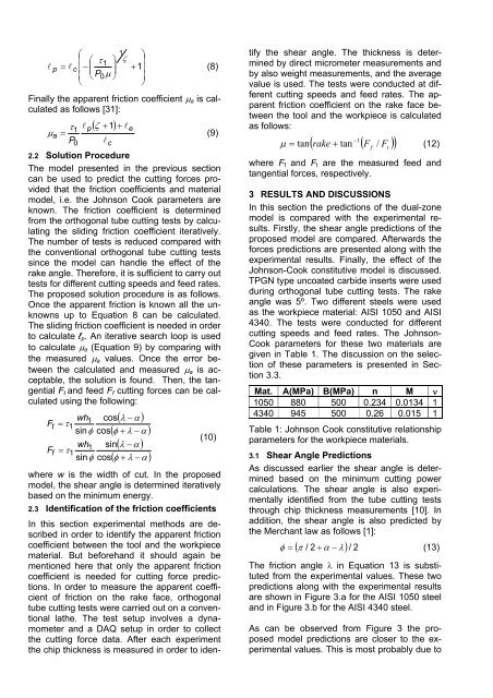
TPGN type uncoated carbide inserts were used<br />
during orthogonal tube cutting tests. The rake<br />
angle was 5º. Two different steels were used<br />
as the workpiece material: AISI 1050 and AISI<br />
4340. The tests were conducted for different<br />
cutting speeds and feed rates. The Johnson-<br />
Cook parameters for these two materials are<br />
given in Table 1. The discussion on the selection<br />
of these parameters is presented in Section<br />
3.3.<br />
Mat. A(MPa) B(MPa) n M ν<br />
1050 880 500 0.234 0.0134 1<br />
4340 945 500 0.26 0.015 1<br />
Table 1: Johnson Cook constitutive relationship<br />
parameters for the workpiece materials.<br />
3.1 Shear Angle Predictions<br />
As discussed earlier the shear angle is determined<br />
based on the minimum cutting power<br />
calculations. The shear angle is also experimentally<br />
identified from the tube cutting tests<br />
through chip thickness measurements [10]. In<br />
addition, the shear angle is also predicted by<br />
the Merchant law as follows [1]:<br />
( π / 2 + α λ)<br />
/ 2<br />
φ = −<br />
(13)<br />
The friction angle λ in Equation 13 is substituted<br />
from the experimental values. These two<br />
predictions along with the experimental results<br />
are shown in Figure 3.a for the AISI 1050 steel<br />
and in Figure 3.b for the AISI 4340 steel.<br />
As can be observed from Figure 3 the proposed<br />
model predictions are closer to the experimental<br />
values. This is most probably due to<br />
f<br />
t