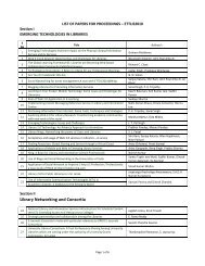
t - Sabanci University Research Database
t - Sabanci University Research Database
t - Sabanci University Research Database

You also want an ePaper? Increase the reach of your titles
YUMPU automatically turns print PDFs into web optimized ePapers that Google loves.
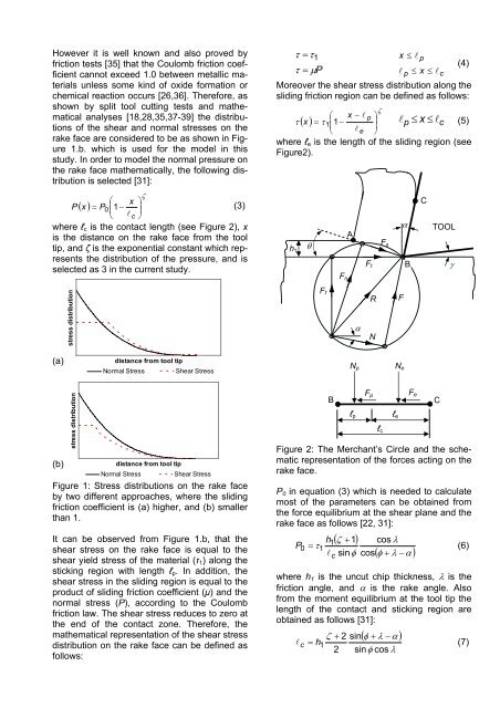
However it is well known and also proved by<br />
friction tests [35] that the Coulomb friction coefficient<br />
cannot exceed 1.0 between metallic materials<br />
unless some kind of oxide formation or<br />
chemical reaction occurs [26,36]. Therefore, as<br />
shown by split tool cutting tests and mathematical<br />
analyses [18,28,35,37-39] the distributions<br />
of the shear and normal stresses on the<br />
rake face are considered to be as shown in Figure<br />
1.b. which is used for the model in this<br />
study. In order to model the normal pressure on<br />
the rake face mathematically, the following distribution<br />
is selected [31]:<br />
P<br />
( x )<br />
ζ<br />
⎛ x ⎞<br />
= P0<br />
⎜ ⎟<br />
⎜<br />
1−<br />
(3)<br />
⎟<br />
⎝ � c ⎠<br />
where ℓc is the contact length (see Figure 2), x<br />
is the distance on the rake face from the tool<br />
tip, and ζ is the exponential constant which represents<br />
the distribution of the pressure, and is<br />
selected as 3 in the current study.<br />
(a)<br />
stress distribution<br />
stress distribution<br />
distance from tool tip<br />
Normal Stress Shear Stress<br />
(b)<br />
distance from tool tip<br />
Normal Stress Shear Stress<br />
Figure 1: Stress distributions on the rake face<br />
by two different approaches, where the sliding<br />
friction coefficient is (a) higher, and (b) smaller<br />
than 1.<br />
It can be observed from Figure 1.b, that the<br />
shear stress on the rake face is equal to the<br />
shear yield stress of the material (τ1) along the<br />
sticking region with length ℓp. In addition, the<br />
shear stress in the sliding region is equal to the<br />
product of sliding friction coefficient (μ) and the<br />
normal stress (P), according to the Coulomb<br />
friction law. The shear stress reduces to zero at<br />
the end of the contact zone. Therefore, the<br />
mathematical representation of the shear stress<br />
distribution on the rake face can be defined as<br />
follows:<br />
τ = τ1<br />
x ≤ � p<br />
(4)<br />
τ = μP<br />
� p ≤ x ≤ �c<br />
Moreover the shear stress distribution along the<br />
sliding friction region can be defined as follows:<br />
τ<br />
( x )<br />
ζ<br />
⎛ x − � p ⎞<br />
= τ ⎜ ⎟<br />
⎜<br />
1 − � 1 ⎟ p x ≤ �c<br />
⎝ � e ⎠<br />
≤ (5)<br />
where ℓe is the length of the sliding region (see<br />
Figure2).<br />
h1<br />
θ<br />
Ff<br />
B<br />
Fn<br />
A<br />
ℓp<br />
Ft<br />
R<br />
α N<br />
Np<br />
Fp<br />
ℓc<br />
Fs<br />
ℓe<br />
F<br />
Ne<br />
α<br />
B<br />
Fe<br />
C<br />
TOOL<br />
Figure 2: The Merchant’s Circle and the schematic<br />
representation of the forces acting on the<br />
rake face.<br />
P0 in equation (3) which is needed to calculate<br />
most of the parameters can be obtained from<br />
the force equilibrium at the shear plane and the<br />
rake face as follows [22, 31]:<br />
P0<br />
h<br />
= τ1<br />
�<br />
1<br />
( ζ + 1)<br />
c<br />
cos λ<br />
sinφ<br />
cos<br />
( φ + λ − α )<br />
C<br />
γ<br />
(6)<br />
where h1 is the uncut chip thickness, λ is the<br />
friction angle, and α is the rake angle. Also<br />
from the moment equilibrium at the tool tip the<br />
length of the contact and sticking region are<br />
obtained as follows [31]:<br />
( φ + λ − α )<br />
ζ + 2 sin<br />
� c = h1<br />
(7)<br />
2 sinφ<br />
cos λ