VCB - Linh Trung
VCB - Linh Trung
VCB - Linh Trung

You also want an ePaper? Increase the reach of your titles
YUMPU automatically turns print PDFs into web optimized ePapers that Google loves.
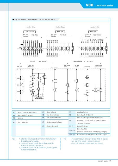
� Fig. 2-2 Standard Circuit Diagram / 그림 2-2 표준 제어 회로도<br />
M1 Motor Operating Mechanism<br />
K1 Anti-Pumping Contactor<br />
R1 Resistor<br />
X0 Plug Connector<br />
Y1 Open Solenoid<br />
Y2 2nd Open Solenoid<br />
Y4 C.T. Operated Release<br />
Y7 Under-Voltage Release<br />
Y9 Closing Solenoid<br />
Note 1. Extended circuit spec & connection line number are<br />
defined by user's request.<br />
2. For the AC control circuit, the rectifier should be<br />
attached on the standard circuit.<br />
3. Standard contacts can be insufficient on the request<br />
of the extended circuit.<br />
<strong>VCB</strong> | HVF/HAF Series<br />
S1 Auxiliary Switch<br />
S3 Limit Switch (K1 Control)<br />
Limit Switch Supplied With the Lockout<br />
S5 (Prevents Closing by Electrical Means When<br />
Lock-Out Effective)<br />
S6, S7 Cutout Switches<br />
S21, S22<br />
Limit Switches<br />
(Interrupt Motor Circuit After Spring Charged)<br />
S41, S42 Position Switch (Spring Charged Status Signal)<br />
주의 1. 추가 회로 및 접속은 고객의 요구에 따라 변경될 수 있습니다.<br />
2. AC 제어전원에 대해서는 정류기가 추가됩니다.<br />
3. 추가 회로 요청시 표준 접점이 부족할 수도 있습니다.<br />
진공차단기 취급설명서 >> 7