ferrites and different winding types in permanent magnet ...
ferrites and different winding types in permanent magnet ...
ferrites and different winding types in permanent magnet ...

You also want an ePaper? Increase the reach of your titles
YUMPU automatically turns print PDFs into web optimized ePapers that Google loves.
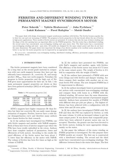
Journal of ELECTRICAL ENGINEERING, VOL. 63, NO. 3, 2012, 162–170<br />
FERRITES AND DIFFERENT WINDING TYPES IN<br />
PERMANENT MAGNET SYNCHRONOUS MOTOR<br />
Peter Sekerák ∗ — Valéria Hrabovcová ∗ — Juha Pyrhönen ∗∗<br />
— Lukáˇs Kalamen ∗ — Pavol Rafajdus ∗ — Matúˇs Onufer ∗<br />
This paper deals with design of <strong>permanent</strong> <strong>magnet</strong> synchronous mach<strong>in</strong>es with <strong>ferrites</strong>. The <strong>ferrites</strong> became popular due<br />
to their low cost <strong>and</strong> cost <strong>in</strong>creas<strong>in</strong>g of NdFeB. The progress <strong>in</strong> ferrite properties <strong>in</strong> the last decade allows the use of <strong>ferrites</strong><br />
<strong>in</strong> high power applications. Three models of ferrite motors are presented. It is shown that also the type of stator <strong>w<strong>in</strong>d<strong>in</strong>g</strong> <strong>and</strong><br />
the shape of the slot open<strong>in</strong>g have an important effect on the PMSM properties. The first motor has a distributed <strong>w<strong>in</strong>d<strong>in</strong>g</strong>,<br />
the second motor has concentrated, non-overlapp<strong>in</strong>g <strong>w<strong>in</strong>d<strong>in</strong>g</strong> <strong>and</strong> open stator slots. The third motor has a concentrated<br />
non-overlapp<strong>in</strong>g <strong>w<strong>in</strong>d<strong>in</strong>g</strong> <strong>and</strong> semi - open slots. All models are designed for the same output power <strong>and</strong> they do not have<br />
the same dimensions. The paper shows how important the design of an electric mach<strong>in</strong>e is for excellent motor properties or<br />
better to say how the motor properties can be improved by an appropriate design.<br />
Keywords: concentrated, non-overlapp<strong>in</strong>g <strong>w<strong>in</strong>d<strong>in</strong>g</strong>, distributed <strong>w<strong>in</strong>d<strong>in</strong>g</strong>, efficiency, <strong>permanent</strong> <strong>magnet</strong> synchronous<br />
motor (PMSM), ferrite<br />
1 INTRODUCTION<br />
The ferrite <strong>permanent</strong> <strong>magnet</strong>s have been considered<br />
for a long time as the second grade material <strong>in</strong> comparison<br />
with rare earth <strong>magnet</strong>s because they have got significantly<br />
lower remanence Br, coercivity Hc <strong>and</strong> energy<br />
product BHmax than rare earth <strong>magnet</strong>s. Nowadays the<br />
progress <strong>in</strong> ferrite properties <strong>and</strong> the high cost of Nd-<br />
FeB gives more opportunities for their use. In Tab. 1 the<br />
ma<strong>in</strong> <strong>permanent</strong> <strong>magnet</strong> properties are shown as they<br />
havebeengatherednowadays(2012)atwebpagesoftheir<br />
producers.<br />
Table 1. PM material properties [5,6]<br />
BHmax Br Hc<br />
NdFeB 200–500 0.97–1.45 740–1000<br />
SmCo 120–240 0.85–1.10 620–840<br />
Ferrite 7–42 0.20–0.48 120–360<br />
AlNiCo 10–35 0.60–1.16 40–120<br />
AlNiCo <strong>magnet</strong>s have higher remanence Br than <strong>ferrites</strong><br />
but their low coercivity Hc can easily cause de<strong>magnet</strong>ization<br />
of <strong>magnet</strong>s. Ferrites, however have a wide l<strong>in</strong>ear<br />
de<strong>magnet</strong>ization curve <strong>and</strong> therefore many authors<br />
have chosen <strong>ferrites</strong> for their research.<br />
In [1] the authors have <strong>in</strong>vestigated two PMSMs; one<br />
with ferrite <strong>magnet</strong>s <strong>and</strong> another with NdFeB <strong>magnet</strong>s.<br />
Bothofthem havebeen of<strong>in</strong>terior<strong>magnet</strong>type wherethe<br />
PMs have been totally embedded <strong>in</strong> the rotors. Authors<br />
have done complete analysis of parameters, losses <strong>and</strong><br />
efficiencies of both motors. Accord<strong>in</strong>g to the results the<br />
rated efficiency of the ferrite motor has been about 1<br />
% lower than the efficiency <strong>in</strong> the motor with NdFeB.<br />
The volume of <strong>ferrites</strong> has been five times as high as the<br />
volume of NdFeB.<br />
In [2] the authors have presented two PMSMs, one<br />
with SmCo <strong>magnet</strong>s <strong>and</strong> another, aga<strong>in</strong>, with <strong>ferrites</strong>.<br />
The efficiency of the ferrite motor was about 0.5 % lower<br />
at the same output power. The weight of <strong>ferrites</strong> is 2.5fold<br />
<strong>in</strong> comparison with the weight of SmCo.<br />
In [3] the authors have presented a PMSM with new<br />
rotor design <strong>and</strong> with <strong>ferrites</strong> <strong>and</strong> damper <strong>w<strong>in</strong>d<strong>in</strong>g</strong>. Authors<br />
compare their mach<strong>in</strong>e with another one at constant<br />
ferrite PM volume. The new designed PMSM has 4<br />
% improvement <strong>in</strong> efficiency.<br />
In [4] the authors <strong>in</strong>vestigate losses<strong>in</strong> <strong>permanent</strong> <strong>magnet</strong><br />
motors with concentrated non-overlapp<strong>in</strong>g <strong>w<strong>in</strong>d<strong>in</strong>g</strong>s<br />
<strong>and</strong> compare them with losses <strong>in</strong> a PMSM with distributed<br />
<strong>w<strong>in</strong>d<strong>in</strong>g</strong>. All motors have the same dimensions,<br />
airgaplength<strong>and</strong>thesameamountof<strong>permanent</strong><strong>magnet</strong><br />
material. Authors have presented five models of PMSM<br />
with <strong>different</strong> slots per pole per phase q. The highest efficiency<br />
has been achieved with a configuration with 24<br />
stator slots <strong>and</strong> 20 rotor poles.<br />
In [9] the authors have <strong>in</strong>vestigated PMSM with Nd-<br />
FeB <strong>and</strong> then the PM was replaced by <strong>ferrites</strong>: a) with<br />
the same volume, b) with an <strong>in</strong>creased volume to get the<br />
same output power. It was shown that comparable properties<br />
have been achieved if greater motor size can be<br />
accepted. Therefore, the greater care has been devoted to<br />
the ferrite motors, look<strong>in</strong>g for more appropriate design,<br />
ma<strong>in</strong>ly on the stator.<br />
In this paper the <strong>in</strong>fluence of the stator <strong>w<strong>in</strong>d<strong>in</strong>g</strong> on<br />
PMSM properties is <strong>in</strong>vestigated. For this purpose three<br />
PMSM models are created. The first one is constructed<br />
with a distributed <strong>w<strong>in</strong>d<strong>in</strong>g</strong>. The second <strong>and</strong> the third<br />
model have concentrated non-overlapp<strong>in</strong>g <strong>w<strong>in</strong>d<strong>in</strong>g</strong>s. The<br />
difference between them is the stator slot shape: The first<br />
∗ University of ˇ Zil<strong>in</strong>a, Faculty of Electrical Eng<strong>in</strong>eer<strong>in</strong>g, Univerzitná 1, 010 26 ˇ Zil<strong>in</strong>a, Slovakia, valeria.hrabovcova.@uniza.sk<br />
∗∗ Lappeenranta University of Technology, Lappeenrante, F<strong>in</strong>l<strong>and</strong><br />
DOI: 10.2478/v10187-012-0024-8, ISSN 1335-3632 c○2012 FEI STU
Journal of ELECTRICAL ENGINEERING 63, NO. 3, 2012 163<br />
one is of open slot type <strong>and</strong> the second one is of semi -<br />
closed slot type<br />
2 PMSM DESIGN<br />
The goal of the PMSM design process should be a<br />
motor which can develop required output power with<br />
excellent efficiency <strong>and</strong> at low cost. At first the choice<br />
between NdFeB <strong>and</strong> <strong>ferrites</strong> has been done <strong>in</strong> favour of<br />
<strong>ferrites</strong>. Accord<strong>in</strong>g to [6] the cost per kg of NdFeB is at<br />
present about 30 times the cost of ferrite.<br />
ForthePMSMdesignferritewiththefollow<strong>in</strong>gparameters<br />
<strong>in</strong> operat<strong>in</strong>g temperature of 75 ◦ C was selected: Br<br />
= 0.45 T, Hc = 340 kA/m <strong>and</strong> BHmax = 40 kJm/m 3 .<br />
The all PMSMs have rotor surface <strong>magnet</strong>s. The other<br />
parameters <strong>and</strong> design process will be described below.<br />
2.1 Initial data of PMSM<br />
The <strong>in</strong>itial data of PMSM given <strong>in</strong> Tab. 2 have been<br />
chosen on a base of an exist<strong>in</strong>g PMSM with NdFeB. In<br />
the tables this mach<strong>in</strong>e is designated as ”orig<strong>in</strong>al”.<br />
Table 2. Initial data of PMSM<br />
Data Symbol Value<br />
Shaft power (W) Pout 2000<br />
Speed (rpm) n 360<br />
Torque (Nm) T 53<br />
Phase voltage (V) Usph 230<br />
Phase number (-) m 3<br />
Pole pairs (-) p 6<br />
Frequency (Hz) fs 36<br />
Air-gap length (mm) δ 1+1<br />
Power factor (-) cosφ 0.9<br />
Desired efficiency (-) η 0.9<br />
Coercivity of PM (A/m) Hc 340000<br />
Remanence of PM (T) Br 0.45<br />
Permeability of PM (-) µr 1.054<br />
Relative <strong>magnet</strong>t width (-) αPM 0.8<br />
Stator-core space factor (-) kfe 0.95<br />
Permitted B <strong>in</strong> tooth (T) Bdper 1.5<br />
Permitted B <strong>in</strong> yoke(T) Byper 1<br />
Table 2showsallnecessarydatafor the PMSMdesign.<br />
The <strong>magnet</strong>ic air gap δ is 2 mm allow<strong>in</strong>g 1 mm for a<br />
<strong>magnet</strong> reta<strong>in</strong><strong>in</strong>g r<strong>in</strong>g.<br />
Next the material of the <strong>magnet</strong>ic circuit M800-65was<br />
chosen. The specific loss of this material at 1 T <strong>and</strong> 50 Hz<br />
is p10 = 3.1 Wk/g. Indirect air cool<strong>in</strong>g has been chosen.<br />
ThePMSMconfigurationwillbedescribed<strong>in</strong>chapter2.3.<br />
2.2 Rotor dimensions<br />
It isobviousthatrotorsurfacemounted<strong>ferrites</strong>cannot<br />
provide so high level of <strong>magnet</strong>ic flux density Bδmax1 as<br />
it is recommended <strong>in</strong> technical literature, be<strong>in</strong>g between<br />
0.8 <strong>and</strong> 1.05 T. The targeted maximal value of Bδmax1<br />
<strong>in</strong> ferrite motor was 0.45 T, see FEM analysis, Fig. 8d.<br />
For Pout = 2000 W the l<strong>in</strong>ear current density A = 30<br />
kA/m was selected.<br />
Therotorvolume Vr forratedtorquecanbeestimated<br />
by torque <strong>and</strong> average tangential stress σFtan [7]<br />
Vr = T<br />
, σF tan ≈<br />
2σF tan<br />
ABδmax1cosφ<br />
√<br />
2<br />
(1,2)<br />
where power factor is chosen from Tab. 2.<br />
For the A <strong>and</strong> Bδ values chosen the tangential stress<br />
is σFtan = 7636 Pa <strong>and</strong> the required volume of rotor is<br />
Vr = 3.47×10 −3 m 3 . For this volume the rotor diameter<br />
Dr = 0.19 m <strong>and</strong> equivalent core length l = 0.12 m<br />
have been calculated. There are no cool<strong>in</strong>g channels <strong>and</strong><br />
therefore the core length of the mach<strong>in</strong>e is by, [11]<br />
2.3 Stator <strong>and</strong> PM dimensions<br />
l = l ′ −2δ. (3)<br />
The chosen Bδmax1 represents the amplitude of the<br />
fundamentalharmoniccomponentoftheairgap<strong>magnet</strong>ic<br />
flux density. Due to the rectangular shape of PM, the<br />
waveform of the <strong>magnet</strong>ic flux density <strong>in</strong> the air gap is<br />
approximately rectangular. The maximum value of this<br />
waveform is calculated by<br />
Bmax = πBδmax1<br />
4s<strong>in</strong> � αPMπ<br />
2<br />
� (4)<br />
This value is used for computation of the tooth width<br />
bd (Fig. 6) not to exceed the maximal <strong>magnet</strong>ic flux<br />
density <strong>in</strong> the stator tooth Bdper, see Tab. 2<br />
bd = l′ τu<br />
kFel<br />
Bmax<br />
Bdper<br />
, τu = πDs<br />
Q<br />
(5,6)<br />
where τu is the slot pitch, with the stator bore diameter<br />
Ds = Dr+2δ . For the stator dimension it is necessary to<br />
calculate the slotdimensions. The first step isto calculate<br />
the stator turns needed for the <strong>in</strong>duced EMF by PM <strong>in</strong><br />
the first step equal to Usph<br />
Ns =<br />
Usph<br />
√ . (7)<br />
2πfk1sΦav<br />
where kws is the operat<strong>in</strong>g harmonic <strong>w<strong>in</strong>d<strong>in</strong>g</strong> factor, see<br />
chapter 3, Φav is the amount of <strong>magnet</strong>ic flux per pole<br />
<strong>and</strong> can be calculated by<br />
Φav = 2<br />
π Bδmax1<br />
Dsπ<br />
2p l′ . (8)<br />
When the number ofstator turns is known the number<br />
of conductors <strong>in</strong> one slot can be determ<strong>in</strong>ed<br />
zQ = Ns/pq, (9)<br />
here zQ has to be <strong>in</strong>tegral number <strong>and</strong> due to it can be<br />
rounded.Nextprocedureisfocusedoncalculationofcross<br />
section area of all conductors. The RMS stator current Is<br />
has to be estimated by<br />
Is =<br />
P<br />
mηUsphcosφ<br />
(10)
164 P. Sekerák et al: FERRITES AND DIFFERENT WINDING TYPES IN PERMANENT MAGNET SYNCHRONOUS MOTOR<br />
Fig. 1. The stator slots: (a) – distributed <strong>w<strong>in</strong>d<strong>in</strong>g</strong>, (b) – concentrated non-overlapp<strong>in</strong>g <strong>w<strong>in</strong>d<strong>in</strong>g</strong>, open slot type, (c) – concentrated<br />
non-overlapp<strong>in</strong>g <strong>w<strong>in</strong>d<strong>in</strong>g</strong>, semi-closed slot type<br />
The stator current density has been selected to Js = 2.5<br />
A/mm 2 . The cross sectional area of the stator slot can<br />
be determ<strong>in</strong>ed<br />
SCS = Is<br />
zQ<br />
Js kCS<br />
(11)<br />
where kCS is the <strong>w<strong>in</strong>d<strong>in</strong>g</strong> space factor which takes <strong>in</strong>to<br />
account the <strong>in</strong>sulation. The calculated stator parameters<br />
to both k<strong>in</strong>ds of <strong>w<strong>in</strong>d<strong>in</strong>g</strong> are shown <strong>in</strong> Tab. 3.<br />
Table 3. Stator parameters<br />
W<strong>in</strong>d<strong>in</strong>g Distri- Concen- Orig<strong>in</strong>al<br />
buted trated PMSM<br />
Bmax (T) 0.37 0.5080<br />
τu (m) 0.0127 0.0338 0.0097<br />
bd (mm) 3.4 9.15 4.3<br />
Ns (-) 840 912 420<br />
zQ (-) 112 0.0338 56<br />
Is (A) 304 4.9*<br />
SCS (mm 2 ) 233 636 141<br />
*value obta<strong>in</strong>ed at rated load <strong>and</strong> optimal<br />
stator phase voltage Usph=180 V<br />
When the parameter SCS is known it is possible to<br />
calculate stator slot dimensions. The crosssectional areas<br />
of slots are shown <strong>in</strong> Fig. 1 (a) – for distributed <strong>w<strong>in</strong>d<strong>in</strong>g</strong>,<br />
(b)–forconcentratednon-overlapp<strong>in</strong>g<strong>w<strong>in</strong>d<strong>in</strong>g</strong>with open<br />
slottype,<strong>and</strong>(c)–concentratednon-overlapp<strong>in</strong>g<strong>w<strong>in</strong>d<strong>in</strong>g</strong><br />
with semi-closed slot type.<br />
For a better underst<strong>and</strong><strong>in</strong>g the motor with distributed<br />
<strong>w<strong>in</strong>d<strong>in</strong>g</strong> is called motor A, motor with concentrated nonoverlapp<strong>in</strong>g<br />
<strong>w<strong>in</strong>d<strong>in</strong>g</strong> <strong>and</strong> open slot type is motor B <strong>and</strong><br />
motor with concentrated non-overlapp<strong>in</strong>g <strong>w<strong>in</strong>d<strong>in</strong>g</strong> <strong>and</strong><br />
semi-closed slot type is motor C.<br />
All dimensions <strong>in</strong> Fig. 1 are given <strong>in</strong> Tab. 4. The<br />
Carters factor has been calculated on the base of the slot<br />
dimensions.<br />
Table 4. Slot dimensions <strong>and</strong> Carter’s factor<br />
Motor A-type B-type C-type<br />
b1 (mm) 3 21.16 6.85<br />
b4 (mm) 9.76 25.83 25.83<br />
h1 (mm) 1 1 1<br />
h2 (mm) 2.1 2.1 2.1<br />
h3 (mm) 1 1 1<br />
h4 (mm) 22.54 20.54 20.54<br />
h ′ (mm) 0.5 0.5 0.5<br />
kC (-) 1.007 1.99 1.09<br />
AsitisseenmotorBhasthelargestCarter’scoefficient<br />
kC, what is caused by the big slot open<strong>in</strong>g. This is used<br />
to calculate equivalent air gap<br />
δe = kCδ (12)<br />
The <strong>magnet</strong>ic voltage of the air gap is given by<br />
Umδδ = Bmax<br />
δe (13)<br />
µ0<br />
where µ0 is the permeability of vacuum.<br />
The total <strong>magnet</strong>ic voltage Umtot is equal to the current<br />
l<strong>in</strong>kage HchPM<br />
Umtot = Umδδ +UmPM +Umds+<br />
+ Umys Umyr<br />
+ = HchPM<br />
2 2<br />
(14)<br />
where Umds, Umys <strong>and</strong> Umyr are the <strong>magnet</strong>ic voltages<br />
of stator tooth, stator yoke <strong>and</strong> rotor yoke, respectively.<br />
The <strong>magnet</strong>ic voltage over the <strong>permanent</strong> <strong>magnet</strong> is<br />
UmPM = Hc<br />
BmaxhPM (15)<br />
Br<br />
In practice the <strong>magnet</strong>ic voltages <strong>in</strong> iron parts of electric<br />
mach<strong>in</strong>e are small <strong>in</strong> comparison with <strong>magnet</strong>ic voltages<br />
over air gap or, especially, the <strong>permanent</strong> <strong>magnet</strong>. Therefore,the<br />
<strong>magnet</strong>icvoltages Umds, Umys <strong>and</strong> Umyr canbe<br />
ignored <strong>in</strong> rotor surface PM mach<strong>in</strong>e without mak<strong>in</strong>g a<br />
big mistake.By substitut<strong>in</strong>g (15) <strong>in</strong>to (14)the <strong>permanent</strong><br />
<strong>magnet</strong> height can be calculated<br />
hPM =<br />
Umδδ<br />
Hc − Hc<br />
Br Bmax<br />
(16)
Journal of ELECTRICAL ENGINEERING 63, NO. 3, 2012 165<br />
The last important dimension for a PMSM design is the<br />
height of the stator yoke hys. Its value can be ga<strong>in</strong>ed on<br />
the base of the <strong>magnet</strong>ic flux <strong>and</strong> cross sectional area of<br />
it<br />
hys =<br />
Φav<br />
2kFelByper<br />
(17)<br />
where kFe <strong>and</strong> Byper are taken from Tab. 2. Table 5<br />
shows the results of the calculated parameters hPM,<br />
wPM <strong>and</strong> hys. These parameters are shown <strong>in</strong> Fig. 6.<br />
Table 5. Calculated parameters hPM , wPM , lPM <strong>and</strong> hys<br />
Motor A-type B-type C-type Orig<strong>in</strong>al<br />
hPM (mm) 15 21 21 4<br />
wPM (mm) 36.6 35.5 35.4 32<br />
lPM (mm) 40 40 40 35<br />
hys (mm) 10 10 10 14.1<br />
3 STATOR WINDING<br />
It is possible to design a PMSM with a distributed<br />
<strong>w<strong>in</strong>d<strong>in</strong>g</strong> <strong>and</strong> also with a concentrated non-overlapp<strong>in</strong>g<br />
<strong>w<strong>in</strong>d<strong>in</strong>g</strong>. Both <strong>w<strong>in</strong>d<strong>in</strong>g</strong> <strong>types</strong> are popular <strong>in</strong> PMSMs <strong>and</strong><br />
<strong>in</strong>thenextchaptersthedesignprocessisshown.Schematically<br />
both <strong>types</strong> are shown <strong>in</strong> Fig. 2.<br />
Fig. 2. Basic scheme of: (a) – distributed <strong>w<strong>in</strong>d<strong>in</strong>g</strong>, (b) – concentrated<br />
<strong>w<strong>in</strong>d<strong>in</strong>g</strong><br />
The concentrated non-overlapp<strong>in</strong>g <strong>w<strong>in</strong>d<strong>in</strong>g</strong> becomes<br />
popular due to its advantages because of very good<br />
manufacturability which decreases cost, shorter nonoverlapp<strong>in</strong>g<br />
end turns or higher power density. The next<br />
chapter3.1showsthatthedesignprocedureofboth<strong>w<strong>in</strong>d<strong>in</strong>g</strong>s<br />
is similar.<br />
3.1 Distributed <strong>w<strong>in</strong>d<strong>in</strong>g</strong><br />
Stator <strong>w<strong>in</strong>d<strong>in</strong>g</strong> is designed as a double layer type. The<br />
statorslotnumber Q hastobechosentonextcalculation.<br />
In the theory of the <strong>w<strong>in</strong>d<strong>in</strong>g</strong> design the concept of ”base<br />
<strong>w<strong>in</strong>d<strong>in</strong>g</strong>” is used. Base <strong>w<strong>in</strong>d<strong>in</strong>g</strong> is a part of the stator<br />
<strong>w<strong>in</strong>d<strong>in</strong>g</strong> which can be repeated periodically. It is possible<br />
to build stator <strong>w<strong>in</strong>d<strong>in</strong>g</strong> by these base <strong>w<strong>in</strong>d<strong>in</strong>g</strong>s due to<br />
their symmetry. The parameters of a base <strong>w<strong>in</strong>d<strong>in</strong>g</strong> are<br />
marked by superscript *. For the PMSM with distributed<br />
<strong>w<strong>in</strong>d<strong>in</strong>g</strong> Q = 45. This number has been chosen on the<br />
baseoftheslotnumber<strong>in</strong>theorig<strong>in</strong>alPMSMwithNdFeB<br />
<strong>magnet</strong>s. The <strong>w<strong>in</strong>d<strong>in</strong>g</strong> with the chosen stator slots <strong>and</strong><br />
pole pairs will be fractional. The number of slots per<br />
phase per pole q is<br />
q = Q z<br />
=<br />
2pm n<br />
Thenextstator<strong>w<strong>in</strong>d<strong>in</strong>g</strong>designdependsonthedenom<strong>in</strong>ator<br />
n <strong>and</strong> the type of <strong>w<strong>in</strong>d<strong>in</strong>g</strong>. It is possible to make<br />
one layeror twolayer<strong>w<strong>in</strong>d<strong>in</strong>g</strong>. Forour configurationwith<br />
45 slots, 6 pole pairs <strong>and</strong> 3 phases is q=5/4. In this case<br />
of even denom<strong>in</strong>ator n the procedure is as follows:<br />
The largest common divider t of slot number Q <strong>and</strong><br />
p <strong>and</strong> further the number of slots of base <strong>w<strong>in</strong>d<strong>in</strong>g</strong>s Q∗<br />
<strong>and</strong> the pole pairs of the base <strong>w<strong>in</strong>d<strong>in</strong>g</strong> p∗ are<br />
t = 2p<br />
n<br />
Q<br />
, Q∗ = , p∗ = n/2<br />
t<br />
The number of layers of the phasor diagram t∗ = 1<br />
for a double layer <strong>w<strong>in</strong>d<strong>in</strong>g</strong>, <strong>and</strong> even number n. Thus<br />
number of Q <strong>and</strong> the angle between two phasors αd <strong>and</strong><br />
the angle between two slots αp is determ<strong>in</strong>ed by<br />
Q ′ = Q∗<br />
t∗ , αd = 360 t∗<br />
Q∗ , αp = 360 p∗<br />
Q∗<br />
Every phase has Q/m phasors. Every phase has two<br />
components, one positive <strong>and</strong> one negative, eg U <strong>and</strong><br />
−U. If the number Q/m is odd the positive <strong>and</strong> negative<br />
component are not equal. For example if Q/m is 5, as <strong>in</strong><br />
our case, the system of <strong>w<strong>in</strong>d<strong>in</strong>g</strong> distribution will be used:<br />
U −W V −U W −V<br />
3 2 3 2 3 2<br />
The distributed <strong>w<strong>in</strong>d<strong>in</strong>g</strong> is assembled of three base<br />
<strong>w<strong>in</strong>d<strong>in</strong>g</strong>s shown <strong>in</strong> Fig. 3.<br />
3.2 Concentrated <strong>w<strong>in</strong>d<strong>in</strong>g</strong><br />
Stator <strong>w<strong>in</strong>d<strong>in</strong>g</strong> is double layer type. For PMSM the<br />
stator slots has been chosen Q = 18. For a configuration<br />
of 18 slots, 6 pole pairs <strong>and</strong> 3 phases, the number of<br />
slots per pole per phase is q = 1/2. See<strong>in</strong>g that n <strong>in</strong><br />
a concentrated nonoverlapp<strong>in</strong>g <strong>w<strong>in</strong>d<strong>in</strong>g</strong> is even as <strong>in</strong> the<br />
distributed <strong>w<strong>in</strong>d<strong>in</strong>g</strong>, the design process is the same.<br />
3.3 W<strong>in</strong>d<strong>in</strong>gs layout<br />
The phasor diagram is necessary for the construction<br />
of the base <strong>w<strong>in</strong>d<strong>in</strong>g</strong>s. Table 6 shows all calculated parameters<br />
mentioned above.<br />
The phasor diagramsof the base <strong>w<strong>in</strong>d<strong>in</strong>g</strong>s constructed<br />
by Tab. 6 are shown <strong>in</strong> Fig. 3a <strong>and</strong> 4a. The arrangements<br />
of both base <strong>w<strong>in</strong>d<strong>in</strong>g</strong>s are shown <strong>in</strong> Fig. 3b <strong>and</strong>
166 P. Sekerák et al: FERRITES AND DIFFERENT WINDING TYPES IN PERMANENT MAGNET SYNCHRONOUS MOTOR<br />
Fig. 3. Distributed base <strong>w<strong>in</strong>d<strong>in</strong>g</strong>: (a) – phasor diagram, (b) –<br />
<strong>w<strong>in</strong>d<strong>in</strong>g</strong> arrangement <strong>in</strong> the slots<br />
Fig. 4. (a) – Phasor diagram of the concentrated non-overlapp<strong>in</strong>g<br />
base <strong>w<strong>in</strong>d<strong>in</strong>g</strong>, (b) – <strong>w<strong>in</strong>d<strong>in</strong>g</strong> arrangement <strong>in</strong> the slots, full l<strong>in</strong>e<br />
represents two base <strong>w<strong>in</strong>d<strong>in</strong>g</strong>s of phase U, dashed l<strong>in</strong>e represents<br />
one base <strong>w<strong>in</strong>d<strong>in</strong>g</strong> of phase V .<br />
Fig. 5. The phasors of the phase U for the calculation of <strong>w<strong>in</strong>d<strong>in</strong>g</strong><br />
factor: (a) – distributed, (b) – concentrated <strong>w<strong>in</strong>d<strong>in</strong>g</strong><br />
4b. The total distributed <strong>w<strong>in</strong>d<strong>in</strong>g</strong> is completed by three<br />
base <strong>w<strong>in</strong>d<strong>in</strong>g</strong>s, shown <strong>in</strong> Fig.3b. The complete concentrated<br />
non-overlapp<strong>in</strong>g <strong>w<strong>in</strong>d<strong>in</strong>g</strong> is assembled of six base<br />
<strong>w<strong>in</strong>d<strong>in</strong>g</strong>s shown <strong>in</strong> Fig. 4b.<br />
Table 6. Stator <strong>w<strong>in</strong>d<strong>in</strong>g</strong> parameters<br />
W<strong>in</strong>d<strong>in</strong>g Distributed Concentrated<br />
Type: double-layer double-layer<br />
q 5/4 1/2<br />
t 3 6<br />
Q∗ 15 3<br />
p∗ 2 1<br />
t∗ 1 1<br />
Q ′ 15 3<br />
αd 24 deg 120 deg<br />
αp 48 deg 120 deg<br />
Q ′ /m 5 1<br />
The <strong>w<strong>in</strong>d<strong>in</strong>g</strong> factors of both <strong>w<strong>in</strong>d<strong>in</strong>g</strong>s for the fundamental<br />
harmonic are determ<strong>in</strong>ed by means of graphics<br />
method shown <strong>in</strong> Fig 5.<br />
4 CROSS SECTION AREA<br />
OF THE DESIGNED PMSM<br />
Fig. 6 shows cross section areas of one quarter of all<br />
three motors. Table 6 shows the f<strong>in</strong>al dimensions of all<br />
three PMSMs <strong>and</strong> also the orig<strong>in</strong>al PMSM.<br />
Table 7. F<strong>in</strong>al dimensions <strong>and</strong> volumes of designed PMSM<br />
Motor A-type B-type C-type Orig<strong>in</strong>al<br />
Drve (m) 0.16 0.148 0.148 0.147<br />
Dse (m) 0.267 0.261 0.261 0.22<br />
PM volume(cm 3 ) 794 1071 1071 215<br />
Iron volume(m 3 ) 0.0042 0.0035 0.00354 0.0041<br />
5 SIMULATION OF THE PMSM OPERATION<br />
In this chapter the operation of designed motors is <strong>in</strong>vestigatedbysimulations.The<br />
ma<strong>in</strong><strong>in</strong>terest isfocused on<br />
V - curves, maximal developed torque <strong>and</strong> ripple torque,<br />
losses <strong>and</strong> efficiency. For this <strong>in</strong>vestigation some parameters<br />
of PMSM have to be known, see Tab. 8. The parameters<br />
have been determ<strong>in</strong>ed by procedures applied <strong>in</strong> [8].<br />
The parameters of orig<strong>in</strong>al motor have been verified by<br />
measurements [8] <strong>and</strong> [9], therefore we suppose that parameters<br />
<strong>and</strong> properties of new designed motors are also<br />
reliable. Parameters from Tab. 8 have been put <strong>in</strong>to the<br />
equivalent circuit model, see Fig. 7.<br />
5.1 Air-gap <strong>magnet</strong>ic flux density<br />
The airgap<strong>magnet</strong>icflux density B<strong>in</strong> allthree motors<br />
hasbeen <strong>in</strong>vestigatedbymeansof2DFEMmodels. Fig.8<br />
showsthewaveformsofB<strong>and</strong>theirharmoniccomponents<br />
at no-load.
Journal of ELECTRICAL ENGINEERING 63, NO. 3, 2012 167<br />
Fig. 6. The cross sectional areas of PMSMs with <strong>different</strong> <strong>w<strong>in</strong>d<strong>in</strong>g</strong> arrangements: (a) – motor A, (b) – motor B, (c) – motor C<br />
Fig. 7. The equivalent circuit of PMSM <strong>in</strong> dq frame<br />
Table 8. PMSM equivalent circuit parameters<br />
Motor A-type B-type C-type Orig<strong>in</strong>al<br />
Rs∗ (Ω) 6.05 4.77 4.77 3.92<br />
Lσs (H) 0.0933 0.0935 0.1489 0.0289<br />
Lµd (H) 0.0297 0.0204 0.0219 0.024<br />
Lµq (H) 0.0297 0.0204 0.0219 0.076<br />
ΨPM (Wb) 1.352 1.179 1.34 0.828<br />
EPM (V) 211 188 213 132.5<br />
* stator resistance at 20 ◦ C<br />
The fundamental components of Bδ are about 0.4 T,<br />
which is very low <strong>in</strong> comparison with PMSM with NdFeB<br />
<strong>magnet</strong>s. NdFeB <strong>magnet</strong>s can provide magnitudes of Bδ<br />
up to 1 T. Low B5 provided by <strong>ferrites</strong> has to be taken<br />
<strong>in</strong>to account <strong>in</strong> a PMSM design <strong>and</strong> a higher number<br />
of stator turns is required, see Tab. 3. As a result the<br />
proportions of iron <strong>and</strong> copper <strong>in</strong> the teeth are changed.<br />
5.2 Torque <strong>in</strong>vestigation<br />
The ability to develop torque is a very important attribute<br />
<strong>in</strong> a PMSM. Fig. 9 shows the maximal values of<br />
developed torque of all three motors.<br />
All threemach<strong>in</strong>esareabletodevelopthe ratedtorque<br />
TN = 53 Nm. The highest torque can be developed by<br />
motor B with Tmax = 90 Nm. On the contrary the maximal<br />
torque of motor C has been lowest Tmax = 68 Nm.<br />
The next parameter <strong>in</strong>vestigated is the ripple torque, see<br />
Fig. 10. All three mach<strong>in</strong>es areloadedby the ratedtorque<br />
TN = 53 Nm.<br />
It is seen that motor A has the lowest torque ripple<br />
<strong>and</strong> its peak to peak value is Tripp = 4 Nm. Motor B has<br />
Tripp = 5.2 Nm. The highest value Tripp has been found<br />
<strong>in</strong> motor C, Tripp = 8.5 Nm.<br />
In synchronous mach<strong>in</strong>es with classical excitation by<br />
means of field current the V - curves present stator current<br />
Is versus field current If. In PMSM these V - curves<br />
are not possible due to constant excitation by PM. The<br />
V-curves <strong>in</strong> this case can be plotted as stator current Is<br />
versus ratio of Usph/EPM at <strong>different</strong> loads. All three<br />
motors have been loaded from 1 kW to 2.5 kW. The stator<br />
term<strong>in</strong>al phase voltage has been changed <strong>in</strong> the range<br />
from 242Vto 173V. The simulated waveformsareshown<br />
<strong>in</strong> Fig. 11.<br />
5.3 V - curves<br />
The V-curves can show the optimal operat<strong>in</strong>g po<strong>in</strong>t<br />
for <strong>different</strong> loads <strong>and</strong> voltage levels. The optimal po<strong>in</strong>t<br />
means the lowest Joule losses that represent the majority<br />
<strong>in</strong> all losses. From Fig. 11 it is seen that the <strong>in</strong>vestigated<br />
motors work very close to this optimal po<strong>in</strong>t. The current<br />
Is at this po<strong>in</strong>t has been chosen as nom<strong>in</strong>al.<br />
5.4 Losses<br />
Losseshavebeen <strong>in</strong>vestigated<strong>in</strong> allthree motors.Next<br />
<strong>types</strong> of losses have been taken <strong>in</strong> to account:<br />
• Joule losses ∆PJ<br />
• Iron losses ∆Piron<br />
• Mechanical losses ∆Pmech<br />
The losses <strong>in</strong> the PM have been calculated accord<strong>in</strong>g<br />
to [10] <strong>and</strong> due their low values they have been neglected.<br />
The ma<strong>in</strong> reason is the high resistivity of <strong>ferrites</strong><br />
<strong>and</strong> therefore the eddy currents <strong>and</strong> eddy current losses<br />
are negligible <strong>in</strong> <strong>ferrites</strong> PM. The resistivity of <strong>ferrites</strong><br />
ρferr = 10 6 Ωcm is very high <strong>in</strong> comparison with the<br />
resistivity of NdFeB ρNdFeB = 2×10 −4 Ωcm.
168 P. Sekerák et al: FERRITES AND DIFFERENT WINDING TYPES IN PERMANENT MAGNET SYNCHRONOUS MOTOR<br />
Fig. 8. The waveforms of B <strong>in</strong>: (a) – motor A, (b) – motor B, (c) – motor C, <strong>and</strong> (d) – their harmonic components<br />
Fig. 9. The maximal developed torque of all three motors at rotor<br />
speed n=360 rpm<br />
The Joule losses are calculated by<br />
∆PJ = 3RsphI 2 s<br />
where Rsph is the phase resistance at 75 ◦ C. Iron losses<br />
<strong>in</strong> n-th element (element means tooth, yoke, etc.) have<br />
been calculated by follow<strong>in</strong>g formula [7]<br />
∆Piron,n = p10<br />
� �2 � �1.3 Bmax,n f<br />
miron,n<br />
1T 50<br />
Fig. 10. The ripple torques of <strong>in</strong>vestigated mach<strong>in</strong>es: (a) — motor A, (b) – motor B, (c) – motor C
Journal of ELECTRICAL ENGINEERING 63, NO. 3, 2012 169<br />
Fig. 11. The V - curves of the <strong>in</strong>vestigated mach<strong>in</strong>es: (a)– motor A, EPM = 211 V, (b) – motor B, EPM = 188 V, (c) – motor C,<br />
EPM = 213 V<br />
Fig. 12. The cross section of the 2D FEM model with <strong>magnet</strong>ic<br />
flux densities description at rated voltage <strong>and</strong> rated load<br />
where p10 = 3.1 W/kg is iron loss per unit of mass at<br />
<strong>magnet</strong>ic flux density B = 1 T, Bmax,n is the amplitude<br />
of the <strong>magnet</strong>ic flux density <strong>in</strong> the n-th element of mach<strong>in</strong>e<br />
<strong>and</strong> miron,n is mass of n-th element of mach<strong>in</strong>e.<br />
The <strong>in</strong>vestigation was done by means of FEM. The amplitude<br />
of the <strong>magnet</strong>ic flux density Bmax,n <strong>in</strong> the n-th<br />
element is given by the tangential <strong>and</strong> normal component<br />
Bmax,n =<br />
�<br />
B 2 max,n,tan +B 2 max,n,norm<br />
that have been taken from 2D FEM model, see Fig. 12.<br />
Figure 13 shows the waveforms of the <strong>magnet</strong>ic flux<br />
densities ga<strong>in</strong>ed from po<strong>in</strong>ts marked <strong>in</strong> Fig. 12.<br />
The mechanical loss has been taken <strong>in</strong>to account <strong>and</strong><br />
its value is Pmech = 40 W for all three motors. This value<br />
has been calculated on the base an analytical approach<br />
<strong>in</strong> [7].<br />
Fig. 13. The <strong>magnet</strong>ic flux densities ofmotorAatthe rated voltage<br />
<strong>and</strong> rated load <strong>in</strong>: (a) – stator yoke, (b) – stator tooth<br />
Figure14showsthelosscomparisonofallthreemotors<br />
at rated voltage <strong>and</strong> load.<br />
Fig. 14. Comparison of losses
170 P. Sekerák et al: FERRITES AND DIFFERENT WINDING TYPES IN PERMANENT MAGNET SYNCHRONOUS MOTOR<br />
On the base of data <strong>in</strong> Fig. 14 the efficiencies for the<br />
motors have been calculated <strong>and</strong> are shown <strong>in</strong> Tab. 9.<br />
Table 9. Calculated efficiency of proposed PMSMs<br />
Motor A-type B-type C-type Orig<strong>in</strong>al<br />
Efficiency (%) 86.5 87.5 88.4 86.5<br />
6 CONCLUSION<br />
The paper shows how the motor properties can be improved<br />
by an appropriate design. A design process of <strong>different</strong><br />
PMSMs has been presented <strong>in</strong> the paper. Three<br />
motors with <strong>ferrites</strong> have been designed, one with distributed<br />
<strong>w<strong>in</strong>d<strong>in</strong>g</strong> <strong>and</strong> two with concentrated <strong>w<strong>in</strong>d<strong>in</strong>g</strong> <strong>and</strong><br />
<strong>in</strong> the end comparedwith a NdFeB SMPM. It is seen that<br />
<strong>ferrites</strong>canbeuseful <strong>in</strong>PMSMdesignalsowhen premium<br />
efficiency is required <strong>and</strong> mach<strong>in</strong>e properties with <strong>ferrites</strong><br />
can be comparable with NdFeB-mach<strong>in</strong>es. A high number<br />
of stator turns is required <strong>in</strong> a PMSM with <strong>ferrites</strong>.<br />
That fact can cause a rapid <strong>in</strong>crease of stator leakage <strong>and</strong><br />
<strong>magnet</strong>iz<strong>in</strong>g<strong>in</strong>ductancewhich leadstolowertorquecapability.<br />
The calculations <strong>and</strong> simulations have shown that<br />
semi closed slot type <strong>in</strong>creases the stator leakage <strong>in</strong>ductance<br />
<strong>and</strong> therefore <strong>in</strong> PMSMs with concentrated nonoverlapp<strong>in</strong>g<br />
<strong>w<strong>in</strong>d<strong>in</strong>g</strong>s the open slot type should be used.<br />
Although the PMSM with <strong>ferrites</strong> requires big volume of<br />
ferrite PM, the cost of <strong>ferrites</strong> is low <strong>in</strong> comparison with<br />
NdFeB.Byus<strong>in</strong>gofaconcentratednon-overlapp<strong>in</strong>g<strong>w<strong>in</strong>d<strong>in</strong>g</strong><br />
the iron parts’ volume has been decreased <strong>in</strong> comparison<br />
with the orig<strong>in</strong>al PMSM with NdFeB.<br />
References<br />
[1] LIANGFANG—LEE, B. H.—LEE, J. J.—KIM, H. J.—JUNG-<br />
PYOHONG: Study on high-efficiency characteristics of <strong>in</strong>terior<br />
<strong>permanent</strong> <strong>magnet</strong> synchronous motor with <strong>different</strong> <strong>magnet</strong><br />
material, Electrical Mach<strong>in</strong>es <strong>and</strong> Systems (2009), ICEMS 2009.<br />
[2] RICHTER, E.—NEUMANN, T.: L<strong>in</strong>e start <strong>permanent</strong> <strong>magnet</strong><br />
motors with <strong>different</strong> material, IEEE Trans. Magnetics 20,<br />
1762–1764.<br />
[3] CHAUDHARI, B. N.—FERNANDES, B. G.: Synchronous motor<br />
us<strong>in</strong>g ferrite <strong>magnet</strong>s for general purpose energy efficient<br />
drive, TENCON 99, 1999,.<br />
[4] JUSSILA, H.—SALMINEN, P.—PYRHONEN, J.: Losses of<br />
a Permanent Magnet Synchronous Motor with Concentrated<br />
W<strong>in</strong>d<strong>in</strong>gs, PEMD, 2006, ISBN: 0-86341-609-8.<br />
[5] www.hitachi-metals.co.jp/e/prod/prod03/p03 10.html.<br />
[6] www.magsy.cz.<br />
[7] PYRHONEN, J., JOKINEN, T., HRABOVCOVA, V.: Design<br />
of rotat<strong>in</strong>g electrical mach<strong>in</strong>es, Wiley, 2008, ISBN: 978-0-470<br />
-69516-6.<br />
[8] SEKERÁK, P.—HRABOVCOVÁ, V.—PRAFAJDUS, P.—<br />
KALAMEN, L.: Interior Permanent Magnet Synchronous Motor<br />
ParametersIdentification, ISEM 2010, Prague,2010, 09,8.-9.<br />
AFC, pp. 107–116, 978-80-01-04621-0.<br />
[9] SEKERÁK, P.—HRABOVCOVÁ—V., KALAMEN—L., RA-<br />
FAJDUS, P.—ONUFER, M.: Synchronous Motors with Different<br />
PM Materials, <strong>in</strong> Proc. of ELEKTRO 2012, 24-25 May,<br />
2012, University of ˇZil<strong>in</strong>a.<br />
[10] PYRHONEN, J.—JUSSILA, H.—ALEXANDROVA, Y.—RA<br />
FAJDUS, P.—NERG, J.: Harmonic loss calculation <strong>in</strong> rotor<br />
surface <strong>permanent</strong> <strong>magnet</strong>s, An analytical approach, early access<br />
article, IEEE Trans. On Magnetics, ISSN: 0018-9464.<br />
[11] PYRHNENJ.—RUUSKANEN, V.—NERG, J.—PURANEN,<br />
J.—JUSSILA, H.: Permanent Magnet Length Effects <strong>in</strong> AC-<br />
Mach<strong>in</strong>es, IEEE Transactions on Magnetics 46 No. 10 (2010),<br />
3783–3789, ISSN 0018-9464 (IF 1.061).<br />
Received 29 September 2011<br />
Peter Sekerák was born <strong>in</strong> Stará Lubovňa, Slovakia, <strong>in</strong><br />
1985. He received the MSc <strong>in</strong> 2009 <strong>in</strong> power electrical systems.<br />
He is now PhD student at the Department of Power Electrical<br />
Systems, University of ˇ Zil<strong>in</strong>a. His research is focused on<br />
<strong>permanent</strong> <strong>magnet</strong> synchronous mach<strong>in</strong>es.<br />
Valeria Hrabovcová graduated <strong>in</strong> electrical eng<strong>in</strong>eer<strong>in</strong>g<br />
from the University of ˇ Zil<strong>in</strong>a <strong>and</strong> ga<strong>in</strong>ed her PhD <strong>in</strong> electrical<br />
eng<strong>in</strong>eer<strong>in</strong>gfromSlovakUniversityofTechnology<strong>in</strong>Bratislava<br />
<strong>in</strong> 1985. She is a full professor of electrical mach<strong>in</strong>es at University<br />
of ˇ Zil<strong>in</strong>a, Faculty of Electrical Eng<strong>in</strong>eer<strong>in</strong>g, Slovakia.<br />
Her professional <strong>and</strong> research <strong>in</strong>terests <strong>in</strong>clude classical, <strong>permanent</strong><br />
<strong>magnet</strong>s <strong>and</strong> electronically commutated electrical mach<strong>in</strong>es.<br />
Juha Pyrhönen received the MSc degree <strong>in</strong> electrical eng<strong>in</strong>eer<strong>in</strong>g,<br />
the Licentiate of Science (Technology) degree, <strong>and</strong><br />
the DSc degree (Technology) from Lappeenranta University<br />
of Technology (LUT), Lappeenranta, F<strong>in</strong>l<strong>and</strong>, <strong>in</strong> 1982, 1989,<br />
<strong>and</strong> 1991, respectively. He has served as associate professor at<br />
Electric Eng<strong>in</strong>eer<strong>in</strong>g LUT, start<strong>in</strong>g <strong>in</strong> 1993 <strong>and</strong> was appo<strong>in</strong>ted<br />
full professor <strong>in</strong> Electrical Mach<strong>in</strong>es <strong>and</strong> Drives <strong>in</strong> 1997. He<br />
worked as the head of the Department of Electrical Eng<strong>in</strong>eer<strong>in</strong>g<br />
from 1998 to 2006. He is active <strong>in</strong> the research on <strong>and</strong><br />
development of electric motors <strong>and</strong> electric drives.<br />
Lukáˇs Kalamen was born <strong>in</strong> 1986 <strong>in</strong> Myjava, Slovakia.<br />
After graduat<strong>in</strong>gat theFacultyof Electrical Eng<strong>in</strong>eer<strong>in</strong>g, University<br />
of il<strong>in</strong>a <strong>in</strong> 2009, he received theMSc degree <strong>in</strong> electrical<br />
drives. Currently, he is a PhD student at the same university.<br />
His ma<strong>in</strong> research <strong>in</strong>terest <strong>in</strong>cludes electrical mach<strong>in</strong>es ma<strong>in</strong>ly<br />
w<strong>in</strong>d power systems equipped with <strong>in</strong>duction generators.<br />
Pavol Rafajdus was born <strong>in</strong> Trnava, Slovakia, <strong>in</strong> 1971.<br />
He received the MSc degree <strong>in</strong> electrical eng<strong>in</strong>eer<strong>in</strong>g <strong>and</strong> the<br />
PhD from University of ˇ Zil<strong>in</strong>a, Slovakia, <strong>in</strong> 1995 <strong>and</strong> 2002,<br />
respectively. At present he is an associate professor at the<br />
Faculty of Electrical Eng<strong>in</strong>eer<strong>in</strong>g, University of ˇ Zil<strong>in</strong>a. His<br />
research is focused on the electrical mach<strong>in</strong>es, ma<strong>in</strong>ly switched<br />
reluctance motors <strong>and</strong> other electrical mach<strong>in</strong>e properties.<br />
Matúˇs Onuferwas born<strong>in</strong>Vranovn.T., Slovakia<strong>in</strong>1987.<br />
He graduated from the University of ˇZil<strong>in</strong>a, where he received<br />
theMSc<strong>in</strong>2011<strong>in</strong>powerelectrical eng<strong>in</strong>eer<strong>in</strong>g.HeisnowPhD<br />
student at the Department of Power Electrical Systems on the<br />
University of ˇ Zil<strong>in</strong>a <strong>and</strong> his research is focused on synchronous<br />
mach<strong>in</strong>es with hybrid excitation.