SENSITIVITY OF VEMA-04.1 MAGNETOMETER
SENSITIVITY OF VEMA-04.1 MAGNETOMETER
SENSITIVITY OF VEMA-04.1 MAGNETOMETER

You also want an ePaper? Increase the reach of your titles
YUMPU automatically turns print PDFs into web optimized ePapers that Google loves.
Journal of ELECTRICAL ENGINEERING, VOL 61. NO 7/s, 2010, 28-31<br />
<strong>SENSITIVITY</strong> <strong>OF</strong> <strong>VEMA</strong>-<strong>04.1</strong> <strong>MAGNETOMETER</strong><br />
Jozef Hudák* ─ Josef Blažek* ─ Dušan Praslička*<br />
─ Ivan Mikita* ─ Pavol Lipovský* ─ Patrik Gonda*<br />
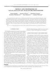
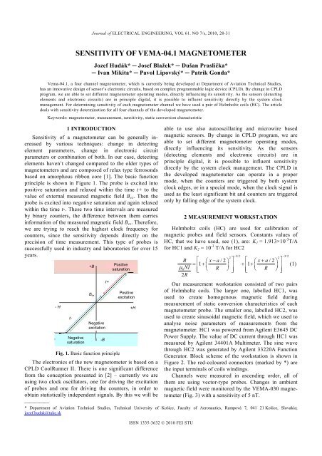
Vema-<strong>04.1</strong>, a four channel magnetometer, which is currently being developed at Department of Aviation Technical Studies,<br />
has an innovative design of sensor’s electronic circuits, based on complex programmable logic device (CPLD). By change in CPLD<br />
program, we are able to set different magnetometer operating modes, directly influencing its sensitivity. As the sensors (detecting<br />
elements and electronic circuits) are in principle digital, it is possible to influent sensitivity directly by the system clock<br />
management. For determining sensitivity of each magnetometer channel we have used a pair of Helmholtz coils (HC). The article<br />
deals with sensitivity determination for all four channels of the developed magnetometer.<br />
Keywords: magnetometer, measurement, sensitivity, static conversion characteristic<br />
1 INTRODUCTION<br />
Sensitivity of a magnetometer can be generally increased<br />
by various techniques: change in detecting<br />
element parameters, change in electronic circuit<br />
parameters or combination of both. In our case, detecting<br />
elements haven’t changed compared to the older types of<br />
magnetometers and are composed of relax type ferrosonds<br />
based on amorphous ribbon core [1]. The basic function<br />
principle is shown in Figure 1. The probe is excited into<br />
positive saturation and relaxed within the time t+ to the<br />
value of external measured magnetic field Bex. Then the<br />
probe is excited into negative saturation and again relaxed<br />
within the time t-. These two time intervals are measured<br />
by binary counters, the difference between them carries<br />
information of the measured magnetic field Bex. Therefore,<br />
we are trying to reach the highest clock frequency for<br />
counters, since the sensitivity depends directly on the<br />
precision of time measurement. This type of probes is<br />
successfully used in industry and laboratories for over 15<br />
years.<br />
- H<br />
t-<br />
Negative<br />
saturation<br />
+B<br />
Bex<br />
Negative<br />
excitation<br />
-B<br />
t+<br />
Fig. 1. Basic function principle<br />
Positive<br />
saturation<br />
Positive<br />
excitation<br />
The electronics of the new magnetometer is based on a<br />
CPLD CoolRunner II. There is one significant difference<br />
from the conception presented in [2] – currently we are<br />
using two clock oscillators, one for driving the excitation<br />
of probes and one for driving the counters, in order to<br />
obtain statistically independent signals. By this we will be<br />
+H<br />
<br />
* Department of Aviation Technical Studies, Technical University of Košice, Faculty of Aeronautics, Rampová 7, 041 21 Košice, Slovakia;<br />
jozef.hudak@tuke.sk<br />
ISSN 1335-3632 © 2010 FEI STU<br />
able to use also autooscillating and microwire based<br />
magnetic sensors. By change in CPLD program, we are<br />
able to set different magnetometer operating modes,<br />
directly influencing its sensitivity. As the sensors<br />
(detecting elements and electronic circuits) are in<br />
principle digital, it is possible to influent sensitivity<br />
directly by the system clock management. The CPLD in<br />
the developed magnetometer can operate in a proper<br />
mode, when the counters are triggered by both system<br />
clock edges, or in a special mode, when the clock signal is<br />
used as the least significant bit and counters are triggered<br />
only by falling edge of the system clock.<br />
2 MEASUREMENT WORKSTATION<br />
Helmholtz coils (HC) are used for calibration of<br />
magnetic probes and field sensors. Constants values of<br />
HC, that we have used, see (1), are: K1 = 1.913×10 -3 T/A<br />
for HC1 and K2 = 10 -3 T/A for HC2<br />
3/2 3/2<br />
2 2<br />
B xa/2 xa/2 <br />
1 1<br />
0NI<br />
<br />
R<br />
<br />
<br />
R<br />
<br />
<br />
2R<br />
Our measurement workstation consisted of two pairs<br />
of Helmholtz coils. The larger one, labelled HC1, was<br />
used to create homogenous magnetic field during<br />
measurement of static conversion characteristics of each<br />
magnetometer probe. The smaller one, labelled HC2, was<br />
used to create sinusoidal magnetic field, which we used to<br />
analyse noise parameters of measurements from the<br />
magnetometer. HC1 was powered from Agilent E3645 DC<br />
Power Supply. The value of DC current through HC1 was<br />
measured by Agilent 34401A Multimeter. The sine wave<br />
through HC2 was generated by Agilent 33220A Function<br />
Generator. Block scheme of the workstation is shown in<br />
Figure 2. The red-coloured connectors (marked by *) are<br />
the input terminals of coils windings.<br />
Channels were measured in ascending order, all of<br />
them are using vector-type probes. Changes in ambient<br />
magnetic field were monitored by the <strong>VEMA</strong>-030 magnetometer<br />
(Fig. 3) with a sensitivity of 5 nT.<br />
(1)
Journal of ELECTRICAL ENGINEERING, VOL 61. NO 7/s, 2010 29<br />
* *<br />
* *<br />
Fig. 2. Block scheme of the measurement workstation<br />
Bn (T)<br />
6.10<br />
6.12<br />
6.14<br />
6.16<br />
6.18<br />
6.20<br />
100 200 300 400 500 600 700<br />
6.10<br />
6.12<br />
6.14<br />
6.16<br />
6.18<br />
6.20<br />
100 200 300 400 500 600 700<br />
Time (min)<br />
Fig. 3. Magnetic field recorded by <strong>VEMA</strong>-030<br />
3 MEASUREMENT RESULTS<br />
During our measurement we obtained static<br />
characteristics of the probes as they are shown in Figure 4.<br />
From these characteristic we could specify the range of<br />
the magnetic field induction, in which we can safely use<br />
these probes. This range was determined in values from -<br />
100 μT to +100 μT. Current clock oscillator, that drives<br />
the counters of the magnetometer, has the frequency of<br />
100 MHz. The counters are in dual-edge triggered mode<br />
which means that 1 count equals 5 ns. The 100 MHz<br />
frequency is used for these reasons:<br />
It is below the maximal reachable frequency value in<br />
order to avoid possible signal glitches that may occur<br />
when working with the highest possible value.<br />
It gives us sufficient precision and sensitivity for<br />
optimization of the program in CPLD and analogue<br />
electronics.<br />
It is standardized value of clock oscillator frequency.<br />
As can be seen, characteristic of each channel slightly<br />
differs. An analysis was performed in order to specify<br />
steepness, offset and non-linearity of the characteristics<br />
and it was done with the use of open-source program<br />
QtiPlot. Values of mentioned parameters are shown in<br />
Tab. 1.<br />
Table 1. Channels parameters<br />
Channel Steepness Offset Full scale non-<br />
1 0.76 7675 1.77<br />
2 0.76 7427 1.16<br />
3 0.75 7802 1.53<br />
4 0.69 6872 0.95<br />
The difference in sign of magnetic field between<br />
record from <strong>VEMA</strong>-030 and the offsets from Tab. 1 is<br />
caused by orientation of the probes – they were oriented<br />
against each other.<br />
Counts<br />
Bn (T)<br />
Fig. 4. Static characteristics of the probes<br />
Since we are using digital data processing, we can<br />
enhance the precision of the measurement by<br />
approximating the conversion characteristics with polynomial<br />
fitting curve of third order (Fig. 5). Increase in<br />
polynomial order would surely result into better precision,<br />
but we are not increasing it, as the required computing<br />
performance rises much faster than the value of obtained<br />
precision.<br />
In our magnetometer, the CPLD is communicating<br />
with MBED microcontroller based on the NXP LPC1768,<br />
which is providing interface to USB port of the<br />
measurement server. MBED also computes the differences<br />
between relaxation time intervals that are carrying the<br />
information about value of the measured magnetic field<br />
and so lowers the computing load of the measurement<br />
server. Information sent by MBED is number of counts, so
30 J. Hudák − J. Blažek − D. Praslička − I. Mikita − P. Lipovský − P. Gonda: <strong>SENSITIVITY</strong> <strong>OF</strong> <strong>VEMA</strong>-<strong>04.1</strong> <strong>MAGNETOMETER</strong><br />
we need to specify the equations for conversion to the<br />
value of magnetic field, while counts is an independent<br />
variable.<br />
B (nT)<br />
Counts<br />
Fig. 5. Difference in approximations<br />
Current values of sensitivities and transfer constants<br />
for each channel of the developed magnetometer, with<br />
clock frequency of 100 MHz and dual-edge triggered<br />
counters, are shown in Table 2.<br />
Table 2. Sensitivities and transfer constants<br />
Channel Sensitivity<br />
(count/nT)<br />
Transfer constant<br />
(nT/count)<br />
1 0.76 1.31<br />
2 0.76 1.32<br />
3 0.75 1.33<br />
4 0.69 1.44<br />
Transfer constant (nT/count)<br />
Clock frequency (MHz)<br />
Fig. 6. Estimated sensitivity<br />
In the nearest future, we are going to increase the<br />
clocking frequency of counters in the magnetometer. As<br />
the CoolRunner II CPLD has top clock frequency limit of<br />
256 MHz for single-edge triggered counters [3], in order<br />
to achieve better sensitivity we have to overcome one<br />
fundamental problem.<br />
Counts<br />
Time (s)<br />
Fig. 7. Example of measured signal waveform after<br />
MWA20<br />
When implementing dual-edge triggered counters, the<br />
frequency limit decreases to 128 MHz. This is the reason<br />
why we are going to use the clock signal as the least<br />
significant bit (LSB) and single-edge triggered counters.<br />
Counts<br />
Time (s)<br />
With good design structure of program within CPLD<br />
we estimate to obtain clocking frequency of 200 MHz,<br />
single-edge triggered counters, the clock signal as LSB<br />
and therefore reach the transfer constant below 10 -9<br />
T/count. Figure 6 shows the trend line of measurements<br />
we have done so far. The graph shows, that the transfer<br />
constant just below 10 -9 Fig. 8. Example of measured signal waveform after<br />
MWA50<br />
T/count should be reachable<br />
around frequency of about 300 MHz, if the counters are in<br />
single-edge triggered mode. This estimation is based on<br />
the physical principle of the developed magnetometer and<br />
on the measurements we have done so far, because the<br />
transfer constant and therefore the sensitivity is proportional<br />
to the clock frequency that drives binary counters in<br />
the magnetometer.
Journal of ELECTRICAL ENGINEERING, VOL 61. NO 7/s, 2010 31<br />
Counts<br />
Time (s)<br />
Fig. 9. Example of measured signal waveform<br />
after MWA100<br />
Amplitude<br />
Frequency (Hz)<br />
Fig. 10. Frequency spectrum after offset removal<br />
Table 3. SNR and standard deviations after MWA<br />
SNR = 1.5<br />
Standard<br />
deviation<br />
(counts)<br />
MWA over<br />
20 samples<br />
MWA over<br />
50 samples<br />
MWA over<br />
100 samples<br />
18.24 11.60 8.01<br />
4 BASIC NOISE PARAMETERS<br />
All of the analogue parts of sensors are using exactly<br />
the same component types, so they have almost identical<br />
noise parameters. Measurement was done in our<br />
laboratory, where the industrial 50 Hz field was present.<br />
We also powered HC2 with sine waveform, to<br />
determine signal-to-noise ratio (SNR) and observe<br />
frequency spectrum of measured magnetic field.<br />
Examples of measured signal waveforms, after<br />
application of moving window averaging (MWA) over 20,<br />
50 and 100 samples, are shown in Figures 7, 8, 9. Table 3<br />
shows standard deviations after moving window averages.<br />
Averaging over 100 samples was done in order to<br />
remove from the signal the two known frequencies, 20 Hz<br />
and 50 Hz, and therefore obtain the noise value, which can<br />
be specified as the standard deviation of the signal after<br />
removing known, meaningful (information carrying)<br />
frequencies.<br />
In Figure 10 is shown an example of normalized<br />
frequency spectrum of measured signal after offset<br />
removal. This spectrum was obtained with fast Fourier<br />
transform in QTI Plot. Clearly visible are 20 Hz and 50<br />
Hz frequencies.<br />
5 CONCLUSION<br />
Measurements, that we have done till this time, prove<br />
that the magnetometer transfer constant below 10 -9<br />
T/count is reachable with this type of magnetometer and<br />
probes. Currently we are experiencing some complications,<br />
so the 200 MHz magnetometer prototype is not<br />
finished yet, we are still waiting for a few components to<br />
complete the design, and so we can continue the<br />
measurements.<br />
In the nearest future measurements of deep analysis of<br />
noise parameters of the magnetometer are also planned.<br />
We have to specify values of noises that come from analog<br />
electronics part, from the probe itself and from the digital<br />
part of the magnetometer. And then, based on the results<br />
possibly optimize these parts.<br />
The discussed magnetometer is developed mainly for<br />
these purposes:<br />
a) precise long-term measurements of magnetic field<br />
b) research of magnetic field mapping and imaging<br />
c) research in security systems based on magnetic<br />
sensors<br />
d) upgrading parameters of industrial magnetometers,<br />
for example HFT system – project APVV-0454-07<br />
Acknowledgement<br />
This work was supported by the Slovak Research and<br />
Development Agency under Contract APVV-0454-07 and<br />
by the Cultural and Educational Grant Agency KEGA of<br />
the Slovak Republic under grant No. 3/7117/09.<br />
REFERENCES<br />
[1] PRASLICKA, D.: A Relax-Type Magnetometer Using Amorphous<br />
Ribbon Core. IEEE Transactions on Magnetics, 30/2, 1994, p. 934-935.<br />
ISSN 0018-9464<br />
[2] LIPOVSKÝ, P. - GONDA, P., et al: Conception of Modern<br />
Magnetometer. New Trends in Signal Processing X, Book of Articles,<br />
2010, ISBN 978-80-8040-399-7.<br />
[3] XILINX Inc.: CoolRunner-II CPLD Family, datasheet, 2008.<br />
Available on internet:<br />
http://www.xilinx.com/support/ documentation/data_sheets/ds090.pdf<br />
Received 30 September 2010