Real-time holographic video images with ... - MIT Media Lab
Real-time holographic video images with ... - MIT Media Lab
Real-time holographic video images with ... - MIT Media Lab

Create successful ePaper yourself
Turn your PDF publications into a flip-book with our unique Google optimized e-Paper software.
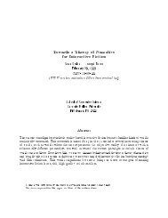
<strong>Real</strong>-<strong>time</strong> <strong>holographic</strong> <strong>video</strong> <strong>images</strong> <strong>with</strong> commodity PC hardware<br />
V. Michael Bove, Jr. *a , Wendy J. Plesniak a,b , Tyeler Quentmeyer a , James Barabas a<br />
a <strong>MIT</strong> <strong>Media</strong> <strong>Lab</strong>oratory, 20 Ames St., Room E15-368B, Cambridge MA 02139 USA<br />
b Harvard Center for Neurodegeneration and Repair, 1249 Boylston St., 2nd Floor Room 425,<br />
Boston MA 02115 USA<br />
ABSTRACT<br />
The <strong>MIT</strong> second-generation <strong>holographic</strong> <strong>video</strong> system is a real-<strong>time</strong> electro-<strong>holographic</strong> display. The system produces a<br />
single-color horizontal parallax only (HPO) <strong>holographic</strong> image. To reconstruct a three-dimensional image, the display<br />
uses a computed fringe pattern <strong>with</strong> an effective resolution of 256K samples wide by 144 lines high by 8 bits per<br />
sample. In this paper we first describe the implementation of a new computational subsystem for the display, replacing<br />
custom computing hardware <strong>with</strong> commodity PC graphics chips, and using OpenGL. We also report the implementation<br />
of stereogram computing techniques that employ the PC hardware acceleration to generate and update <strong>holographic</strong><br />
<strong>images</strong> at rates of up to two frames per second. These innovations shrink the system’s physical footprint to fit on the<br />
table-top and mark the fastest rate at which full computation and update have been achieved on this system to date.<br />
Finally we present first results of implementing the Reconfigurable Image Projection (RIP) method of computing highquality<br />
holograms on this new system.<br />
Keywords: <strong>holographic</strong> <strong>video</strong>, autostereoscopic displays, synthetic holography<br />
1. INTRODUCTION<br />
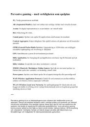
The <strong>MIT</strong> second-generation (“Mark II”) <strong>holographic</strong> <strong>video</strong> system 1 (Fig. 1) is a real-<strong>time</strong> display system that diffracts<br />
light by means of eighteen parallel cross-fired shear mode TeO2 acousto-optic modulators (AOMs) and passes the result<br />
to a chain of optics and scanning mirrors to produce a monochromatic horizontal-parallax-only (HPO) image volume<br />
150mm wide, 75mm high, and 160mm deep, visible over a range of 30 degrees, refreshed 30 <strong>time</strong>s per second, <strong>with</strong> a<br />
vertical resolution of 144 lines. As the optical design of this system has been described at length elsewhere, in this paper<br />
we will concentrate only on the aspects of the system that set requirements for the <strong>video</strong> signals driving it.<br />
The Mark II system is optically very similar to the Scophony 2 television display of the 1930s, differing mostly in the use<br />
of multiple parallel AOMs in place of the latter’s single AOM; the signals differ in that the Scophony system (which<br />
was displaying a single 2D raster) amplitude-modulated a fixed-frequency fringe pattern <strong>with</strong> the intensity of the <strong>video</strong><br />
image, while in Mark II both the amplitude and instantaneous phase of the fringes are varied. Also, Mark II, through its<br />
use of cross-fired AOMs, is able to use both the forward and retrace horizontal scans for active <strong>video</strong>, a technique<br />
some<strong>time</strong>s called a boustrophedonic scanning pattern. This latter feature will have implications for the generation of<br />
<strong>video</strong> signals, as will be discussed in a later section of this paper.<br />
Since its construction in the 1990s, computation for the Mark II system has been performed by a combination of an SGI<br />
Onyx workstation and a Cheops Imaging System, 3 a compact, block data-flow computing system optimized for real<strong>time</strong><br />
parallel computations on streams of data. Because the Cheops system is capable of driving up to six genlocked<br />
<strong>video</strong> output cards whose <strong>video</strong> timing parameters can be freely configured to meet unusual requirements, because it is<br />
easily interfaced to a host workstation by SCSI (and HIPPI, if higher speed is required), and because it contains (for its<br />
<strong>time</strong>, and to some degree even now) a large amount of random-access memory, it was a good match to the needs of the<br />
Mark II display. The modularity of Cheops also permitted the development and installation of specialized basis-function<br />
superposition processors (“Splotch Engines”) which were optimized for the computational needs of the holo-stereogram<br />
algorithm, below. 4<br />
* vmb@media.mit.edu, http://www.media.mit.edu/~vmb
Laser Grating AOMs<br />
H Sync<br />
18 Video<br />
Signals<br />
Vertical<br />
Mirror<br />
V Scanner<br />
Drive<br />
Horizontal<br />
Mirrors<br />
H Scanner<br />
Drive<br />
Viewer<br />
Figure 1: Extremely simplified block diagram of Mark II display system, <strong>with</strong> optical elements deleted for clarity.<br />
One goal for the evolution of this project is the creation of a desktop <strong>holographic</strong> <strong>video</strong> monitor that is approximately<br />
the volume and cost of a current desktop PC monitor, and can be driven by a typical PC. As an initial investigation into<br />
the practicality of such a system, we have undertaken a series of experiments in generating <strong>video</strong> signals for the Mark II<br />
system using commercial PC graphics cards. A collateral advantage of this work is the elimination of an expensive,<br />
nonstandard computing hardware and rendering software system, moving the programming environment to OpenGL<br />
running under Linux.<br />
2. VIDEO REQUIREMENTS<br />
A useful way to think of the Mark II display is as a stack of 144 thin HPO holograms (called “hololines”) each of which<br />
must be updated 30 <strong>time</strong>s per second in order to produce an image for the viewer. As we have 18 AOMs, we need 18<br />
parallel, synchronous <strong>video</strong> signals to drive them. In Cheops, the red, green, and blue outputs of six <strong>video</strong> output cards<br />
were each treated as independent 8-bit monochrome frame buffers, resulting in the needed 18 <strong>video</strong> channels; in the PC<br />
environment we will require either six graphics chips or three dual-head graphics chips to achieve the same result.<br />
The system of mirrors that steers the modulated light consists of a vertical scanning system and a horizontal scanning<br />
system. On input of the first set of 18 fringe patterns, the horizontal scanning system steers the fringe pattern from left<br />
to right over the horizontal range of the image. On the next set of inputs, the horizontal scanning system steers the fringe<br />
pattern in the opposite direction, from right to left. This forward-reverse pattern repeats four <strong>time</strong>s for a frame of<br />
holo<strong>video</strong>, producing 144 hololines. However, it also means that every other fringe pattern is imaged backwards and<br />
therefore needs to be generated in reverse order. As a result of the parallel AOMs, the vertical scanning system is driven<br />
not <strong>with</strong> a smooth sawtooth signal but <strong>with</strong> an ascending series of eight steps, each eighteen lines in height.<br />
Between frames, the vertical scanning mirror needs to return to its starting position. In order to allow it to do so, there is<br />
a vertical retrace <strong>time</strong> between frames equal to one complete horizontal scan (left to right and back to left). Between<br />
horizontal lines, the horizontal scanning mirrors need to slow to a stop and accelerate to their scanning velocity in the<br />
opposite direction. While the horizontal mirrors are imaging lines, they need to move at a constant velocity to avoid<br />
distorting the image data. The horizontal mirrors therefore cannot be used to image data while they are nonlinearly
changing directions. To compensate for this, there is a horizontal blanking interval between hololines of roughly 0.9ms<br />
(empirically determined), out of a total line <strong>time</strong> of 3.3ms.<br />
Each fringe pattern is 2 18 (256K) samples in length laid down over the 150mm wide image zone, giving a horizontal<br />
resolution of 256K/150mm = 1748 samples per millimeter. The horizontal resolution is high enough to diffract light<br />
<strong>with</strong>out obviously visible artifacts. There are 144 vertical lines over the 75mm high image zone, giving 2 lines per<br />
millimeter, equivalent to a 19” NTSC display. The value of 256K samples was chosen because it is easy to generate<br />
<strong>with</strong> the Cheops framebuffer and because it provides a data frequency suitable to the display characteristics.<br />
The display electronics performs several processing steps on the <strong>video</strong> and sync signals from the computing system in<br />
order to generate drive signals for the scanning mirrors and AOMs. Horizontal sync pulses are used to synchronize a<br />
triangle wave generator that controls the horizontal scanning mirrors. The vertical scan signal is generated by<br />
incrementing a counter at every horizontal sync (resetting <strong>with</strong> vertical sync), and driving a digital-to-analog converter<br />
that creates a discretized sawtooth signal. Because the AOMs have an operating range of approximately 50-100MHz,<br />
<strong>video</strong> outputs are low-pass filtered and mixed <strong>with</strong> a 100MHz local oscillator, filtered to retain the lower sideband, and<br />
sent to power amplifiers to drive the AOMs. An analog switch triggered by horizontal sync switches alternating<br />
hololines between the “forward” and “reverse” AOMs.<br />
The Cheops system was configurable to generate a <strong>video</strong> signal that was an exact match to the Mark II’s needs: 30Hz<br />
refresh rate, 8 active lines of 262,142 (256K) pixels each, <strong>with</strong> a horizontal blanking interval and sync pulse at the end<br />
of each line, and a vertical blanking interval and sync pulse each one line long at the end of the frame. In order to<br />
replace the Cheops/SGI combination <strong>with</strong> one or more PCs, the PC <strong>video</strong> cards have to be able to generate eighteen (six<br />
RGB) genlocked <strong>video</strong> outputs at a corresponding resolution and rate. Although many modern graphics chips have the<br />
ability to synchronize to an external source (including those from ATI, NVIDIA, and 3Dlabs), it is a rarely used feature<br />
on PCs and is therefore not brought out to a connector by most <strong>video</strong> card manufacturers. At the <strong>time</strong> we began this<br />
work, mass-market <strong>video</strong> cards supporting this feature were based on only two chips: the NVIDIA Quadro FX 3000G<br />
and the 3Dlabs Wildcat II 5110-G. For driver quality, hardware performance, and future upgradability, we chose to use<br />
the Quadro FX 3000G. At that <strong>time</strong>, PNY was the only board manufacturer <strong>with</strong> a card based on the latter chip. For<br />
power-consumption and bus-bandwidth reasons we configured our system as three dual-head cards each in a separate<br />
inexpensive (sub-$500) PC, <strong>with</strong> a fourth PC providing a graphical user interface to control the system.<br />
The chosen <strong>video</strong> chip isn’t quite as flexible as Cheops, and we must work around several parametric limitations. In<br />
particular, the line length is limited to 4096 pixels. Solving this problem by splitting a hololine among multiple frame<br />
buffer lines will mean that we can’t use the <strong>video</strong> chip’s horizontal blanking to generate our horizontal blanking<br />
interval; instead we will have to set the horizontal blanking parameter as small as possible (to minimize gaps in our<br />
fringe patterns) and add the needed blanking pixels to our active line length, filling them <strong>with</strong> black. To achieve the<br />
desired number of samples, we can make each hololine either 178 vertical lines of 2048 pixels or 89 vertical lines of<br />
4096 pixels. Since 4096 is the maximum line length the software drivers will accept, to allow for future increases in the<br />
number of samples in a hololine, we chose to use 178 vertical lines at 2048 samples per line. In this configuration, we<br />
fill the first 128 lines of each 176 <strong>with</strong> fringe values and the remaining 50 <strong>with</strong> black to generate the hololine blanking<br />
interval. The software drivers won’t let us set the horizontal blanking on each 2048-sample line to zero, so the last 16<br />
samples of each 2048 will be blanked out. This will create small gaps in our diffraction fringes, but we have noted no<br />
visible artifacts as a result. We also add an external divide-by-178 counter between the horizontal sync output and the<br />
input of Mark II. To meet the vertical timing requirements we place 356 blank lines at the top of the frame and 8<br />
vertical sync lines at the end.
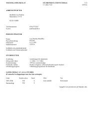
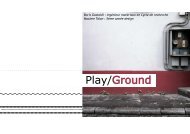
Figure 2: Projecting parallax views by subdividing hologram plane.<br />
3. STEREOGRAM ALGORITHM<br />
Synthetic holograms for electronic displays can be computed by physically-based methods which model the interference<br />
between a reference wave and the scene objects (modeled as a collection of spherical emitters in three-space), by<br />
stereogram methods which render the scene into a set of 2D views and use the diffraction properties of the display to<br />
multiplex them, or by methods that are a hybrid of the two. While physically-based rendering yields very high quality<br />
holograms, the computation is extremely costly, even for HPO displays; when it is desired to update a scene in real <strong>time</strong><br />
using relatively modest computing hardware, a stereogram or hybrid approach may often be more suitable. In this<br />
section we discuss a particular stereogram approach, while in the following section we consider a hybrid algorithm.<br />
The huge computational advantage of stereogram rendering methods arises from their use of precomputed basis fringes<br />
which are modulated by the visual content of a particular scene. A set of N basis fringes performs the task of diffracting<br />
light in N directions, or – more precisely – uniformly illuminating N different small angular extents that span the view<br />
zone of the display. These are independent of the scene content, and in an interactive or dynamic display, they need be<br />
computed only once, not once per <strong>video</strong> frame. In an HPO display, the hololines are independent of one another, each<br />
line being subdivided horizontally into an array of uniform chunks called hogels. Each hogel is a linear superposition of<br />
a set of basis fringes weighted by image pixel values corresponding to the view information that the spatial extent of the<br />
hogel should angularly project into the view zone (Fig. 2). The 8-bit dynamic range of a typical framebuffer will limit<br />
the number of basis fringes (and thus views) that can be multiplexed in a hogel, while aperture effects on scene<br />
resolution point toward making hogels larger; as a consequence of these phenomena the scene parallax is commonly<br />
sampled more coarsely than perceptual considerations would ideally prescribe and the image resolution is lower than in<br />
an interference-modeled hologram of the same scene. In the work presented here, we placed 256 hogels each of length<br />
1024 pixels on each hololine, superposing 32 basis fringes in each hogel. Thus 32 parallax views of a scene, each of<br />
resolution 256x144, need to be rendered and used to modulate the basis fringes.<br />
To display a <strong>holographic</strong> stereogram <strong>with</strong> the SGI/Cheops system, the view <strong>images</strong> were rendered on the SGI and<br />
reorganized into vectors corresponding to the hogels. The result then passed to Cheops where it was combined <strong>with</strong> the<br />
basis fringes to construct a <strong>holographic</strong> fringe pattern that was written to the framebuffers. Thus a significant bandwidth<br />
bottleneck occurred in transmitting the view <strong>images</strong>. In the PC system, we propose to have each <strong>video</strong> card generate the<br />
views from the model and save them to local memory, then use them to modulate the precomputed basis fringes and<br />
write the result to the framebuffer. Only the scene model and data independent program instructions need to be sent<br />
over a relatively slow backplane bus and thus bus bandwidth becomes less of a constraint on system performance.
Lucente and Galyean 5 introduced an algorithm to compute stereographic holograms that uses a graphics workstation’s<br />
hardware accelerated accumulation buffer and texturing units. The texturing units of the graphics processor are used to<br />
modulate basis fringes by view image information. The modulated basis fringes are written to the framebuffer and<br />
summed together using the accumulation buffer. We model our implementation after this accumulation buffer based<br />
algorithm. Until very recently such an approach was not an option for commodity PC graphics cards, as they lacked<br />
hardware accelerated accumulation buffers. Using a software-emulated accumulation buffer to perform the basis fringe<br />
summation would result in slower performance than running the entire computation on the CPU. Petz and Magnor 6<br />
presented a workaround for inexpensive graphics chips that used the texture unit to do summation; since the bit depth of<br />
these units is limited they organized the necessary basis fringe summations into a hierarchy of texture summations in<br />
order to preserve accuracy. As the <strong>video</strong> cards we use provide hardware based accumulation buffers and higher texture<br />
precision, their method is not needed here.<br />
Our basic algorithm is presented in Figure 3. The Quadro FX 3000G has the ability to perform all of its computations<br />
using 32-bit floating-point precision and to retain that precision when storing values in an accumulation buffer. Our new<br />
system therefore meets the numerical precision requirements to compute a <strong>holographic</strong> stereogram. The OpenGL<br />
texture modulation feature is sufficient to modulate a basis fringe <strong>with</strong> an amplitude specified by a view pixel. Either<br />
the accumulation buffer or a custom fragment program is sufficient to sum and normalize the modulated basis fringes<br />
into a complete <strong>holographic</strong> fringe pattern.<br />
Each of the three PCs in the system runs a process responsible for drawing <strong>holographic</strong> fringe patterns to its two<br />
framebuffers. A fourth PC runs a server process to synchronize rendering and control the three PCs in our system, as<br />
well as a user interface for interactive content.<br />
Compute 32 basis fringes on the CPU<br />
Create a 1D texture for each basis fringe<br />
For each frame<br />
Render 32 views of the scene geometry into the framebuffer and create a 2D texture<br />
out of each view<br />
Clear the accumulation buffer<br />
For hololine = 1 to 24<br />
For view = 1 to 32<br />
Clear the framebuffer<br />
Bind basis fringe[view] to texture 1<br />
Bind view image[view] to texture 2<br />
For hogel = 1 to 256<br />
Write texture 1 modulated by texture 2 to the correct location and to the<br />
correct color channel in the framebuffer<br />
Add the framebuffer contents to the accumulation buffer<br />
Divide all values in the accumulation buffer by 32<br />
Write the contents of the accumulation buffer to the framebuffer<br />
Figure 3: Pseudo-code for stereogram rendering algorithm.<br />
We make a number of optimizations to the basic algorithm. First, we pack all of the 1D basis fringe textures into a<br />
single 2D texture where each row of pixels in the 2D texture is a single basis fringe. This eliminates the need to unbind<br />
and bind a new basis fringe texture between views. Second, we pack all of the view <strong>images</strong> into a single 2D texture. We<br />
also render to a pbuffer that can be used directly as a texture instead of reading data from the framebuffer into a texture.<br />
This eliminates the need to unbind and bind the view image textures between views and eliminates the need to copy<br />
pixels from the framebuffer to texture memory. Third, we store the vertex and texture coordinate data needed to<br />
construct the fringe pattern in a display list to minimize the amount of data transferred over slow buses. Fourth, we precompute<br />
the packing of three hololines into the three color channels of a single output pixel. We do this at the stage of<br />
preparing the view textures. We render the 32 views to the red channel of the framebuffer (a pbuffer). We then shift the<br />
viewport up one horizontal line and render the same 32 views to the green channel. Finally, we shift the viewport up one<br />
more line and render the views to the blue channel. To compute the fringe pattern, we render 8 lines using all three of<br />
the color channels (for modest scene geometry, rendering three <strong>time</strong>s as many views is faster than reading data from the
framebuffer, shifting it, and writing it back to the framebuffer). This way, we can modulate view <strong>images</strong> and write out<br />
fringe patterns for three hololines in one parallel step. This optimization reduces the number of texture operations that<br />
need to be performed as well as reducing the amount of data that needs to be written to the framebuffer <strong>with</strong> the color<br />
mask enabled.<br />
4. RIP ALGORITHM<br />
The Reconfigurable Image Projection (RIP) algorithm 7 is intended to combine the speed and efficiency of stereogram<br />
methods <strong>with</strong> the geometric accuracy and realistic appearance of holograms computed using interference modeling.<br />
Instead of projecting the scene through <strong>holographic</strong> primitives (hogels) on the hologram plane, the RIP method instead<br />
projects multiple parallax views of the scene through a set of <strong>holographic</strong>ally-generated image surfaces some distance<br />
away from the hologram plane. The role of the hogel in the stereogram algorithm is here played by a primitive called a<br />
projector fringe, or pfringe, which can be generated by simulating the interference of a reference wave and a wave<br />
emitted from an element of an object (e.g. a point, a line, a small facet). These pfringes are then modulated by a slice<br />
through a volume of rendered or captured parallax views, or they may be generated directly by a specialized rendering<br />
algorithm. The set of modulated pfringes are accumulated into the final hologram in similar fashion to the hogels in a<br />
holo-stereogram, though rather than abut, their footprints partially overlap those of their neighbors on the hologram<br />
plane.<br />
We have programmed a non-optimized OpenGL implementation of the RIP algorithm into our system. Our software<br />
configuration positions a 75.4 x 56.5mm projection plane 4mm in front of the hologram plane. The projection plane is<br />
populated by 383 x 144 points, <strong>with</strong> a horizontal interpoint spacing of 0.19mm. The HPO viewzone is 383mm wide and<br />
590mm in front of the projection plane, into which 140 parallax views are projected <strong>with</strong> an interview spacing of<br />
2.7mm.<br />
The computation takes place in two phases. First, in an initialization step, six processes, each assembling 24 of the 144<br />
hologram lines and rendering them to one of the framebuffers, parse an XML description of the hologram geometry and<br />
the scene to be displayed. From this description, both hologram projection and parallax view rendering geometries are<br />
configured, scene lighting is specified, model material and texture properties are assigned, and geometry display lists<br />
are constructed. Each process computes interference patterns which describe the pfringes, windows them <strong>with</strong> a Kaiser<br />
window to prevent sharp discontinuities at the apertures, and represents them as 1D textures.<br />
Next, in a combined parallax view and hologram rendering phase, each process renders the sweep of 140 parallax views<br />
of the scene and represents it as a 3D texture. Each view is rendered at a resolution of 383x144 pixels <strong>with</strong> a non-square<br />
pixel aspect, according to the capture geometry specified in the initialization step. Then, the RIP hologram rendering<br />
and assembly is accomplished by superposing the set of view modulated pfringes that reconstruct all view-modulating<br />
points in a given framebuffer’s portion of the hologram.<br />
In this work, hologram rendering and assembly are implemented to utilize NVIDIA’s OpenGL hardware support for<br />
multitexturing. Using an orthographic projection, each view modulated projector fringe is rendered as a rectangle the<br />
height of one framebuffer line and width of the projector fringe’s footprint on the hologram, positioned <strong>with</strong>in the<br />
rendering window to reconstruct a holopoint at the correct location on the projection plane, and modulated by both the<br />
fringe texture and an appropriate portion of the parallax view texture.<br />
Since the extent of a modulated pfringe’s footprint will be wider than the rendering window (recall that the hololines are<br />
longer than the longest framebuffer line supported by the NVIDIA chip), it must be made to span multiple framebuffer<br />
lines, beginning on the next line exactly where it was clipped on the previous. This is accomplished most efficiently by<br />
rendering multiple versions of the same textured rectangle, shifted by appropriate amounts to position them correctly<br />
<strong>with</strong>in each framebuffer line spanned. In addition, since the pfringes for adjacent points will partially overlap in a RIP<br />
hologram, their superposition is achieved by enabling pixel blending and defining an appropriate blend function that<br />
scales each contribution such that the final blended result fits <strong>with</strong>in the dynamic range of each 8-bit channel in the<br />
framebuffer.
When all six framebuffers’ holograms are rendered and displayed, the pattern they produce reconstructs a projection<br />
plane populated by holopoints, and each holopoint projects angularly varying view information to reconstruct the<br />
captured scene’s light field. Once a hologram frame has been displayed, each process can modify the scene and<br />
handshake <strong>with</strong> a server to synchronize update and display of the next frame.<br />
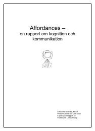
Figure 4: Image of a textured cube photographed from the display.<br />
5. RESULTS AND CONCLUSIONS<br />
In side-by-side comparisons of the <strong>images</strong> generated by the PCs (Fig. 4) <strong>with</strong> <strong>images</strong> generated by the SGI/Cheops<br />
combination, only one significant difference was apparent. Since the screen raster is made up of simultaneous outputs<br />
from multiple <strong>video</strong> cards, any timing variation between the cards is visible as jaggedness in vertical edges. The Cheops<br />
<strong>images</strong> display no such effect, while the three groups of lines in the PC <strong>images</strong> have a small degree of misalignment<br />
suggesting that the card-to-card synchronization is not quite as precise as needed. The relative misalignment changes<br />
each <strong>time</strong> the cards are initialized but appears stable over <strong>time</strong>; we are currently compensating by means of a variable<br />
shift in the <strong>images</strong> on the framebuffers but we are looking into the cause of the underlying problem.<br />
Rendering simple texture-mapped objects using the stereogram algorithm, we observed update rates of approximately 2<br />
frames per second, the fastest rate we have ever achieved for this display system. The computation of any stereogram<br />
can be divided into two parts: computing the view data for the stereogram’s view locations and constructing the<br />
stereogram from the view data. In our case, computing the view data involves rendering 32 different views of the scene<br />
geometry. Constructing the stereogram involves modulating the 32 basis fringes by the view data and accumulating the<br />
modulated fringes. Unlike the rendering step, the speed of the fringe computation step is not dependent on the input<br />
view <strong>images</strong>. In our experiments, we measured the <strong>time</strong> to perform the fringe computation step to be about 0.45 seconds<br />
out of a total of about 0.52 seconds to compute the complete hologram.<br />
Preliminary results from the non-optimized RIP renderer have given us an update rate of approximately .84 seconds per<br />
frame (or approximately 1.2 frames/second) for objects of similar complexity to those reported above.<br />
If performing the 100MHz modulation were possible on the <strong>video</strong> card, the eighteen trouble-prone and bulky external<br />
analog modulators between the PC <strong>video</strong> outputs and the AOMs could be eliminated. As it happens, increasing the line<br />
length to the maximum 4096 pixels raises the pixel clock rate high enough to permit doing so. In order to accomplish<br />
this, a normal 2048 by 1424 pixel fringe pattern could be written to the framebuffer and represented as a texture. A
single rectangle could be drawn that maps to the full 4096 by 1424 pixel output mapped <strong>with</strong> two textures: the fringe<br />
pattern that was read from the framebuffer applied in decal mode, and a pre-computed texture containing a 100MHz<br />
sine wave applied in modulation mode.<br />
6. ACKNOWLEDGEMENTS<br />
This paper is dedicated to the memory of Stephen A. Benton. The authors wish to thank all their colleagues who have<br />
contributed to the development of the Mark II system and to this investigation, in particular Pierre St.-Hilaire and Mark<br />
Lucente. The research reported in this paper was supported by the Digital Life, Things That Think, and CE<strong>Lab</strong> research<br />
consortia at the <strong>MIT</strong> <strong>Media</strong> <strong>Lab</strong>oratory.<br />
REFERENCES<br />
1. P. St.-Hilaire, S. A. Benton, M. Lucente, J. D. Sutter, and W. J. Plesniak, “Advances in Holographic Video,” in<br />
S.A. Benton, ed., SPIE Proc. Vol. #1914: Practical Holography VII, 1993, pp. 188-196.<br />
2. H. W. Lee, “The Scophony Television Receiver,” Nature, 142, July 9, 1938, pp. 59-62.<br />
3. V. M. Bove, Jr. and J. A. Watlington, “Cheops: A Reconfigurable Data-Flow System for Video Processing,” IEEE<br />
Transactions on Circuits and Systems for Video Technology, 5, Apr. 1995, pp. 140-149.<br />
4. J. A. Watlington, M. Lucente, C. J. Sparrell, V. M. Bove, Jr., and I. Tamitani, “A Hardware Architecture for Rapid<br />
Generation of Electro-Holographic Fringe Patterns,” in S.A. Benton, ed., SPIE Proc. #2406: Practical Holography<br />
IX, pp. 172-183.<br />
5. M. Lucente, T. Galyean, “Rendering Interactive Holographic Images,” Proceedings of the 22nd Annual Conference<br />
on Computer Graphics and Interactive Techniques, ACM SIGGRAPH, 1995, pp. 387-394.<br />
6. C. Petz and M. Magnor, “Fast Hologram Synthesis for 3D Geometry Models using Graphics Hardware,” in T. H.<br />
Jeong, S. H. Stevenson, eds., SPIE Proc. Vol. #5005: Practical Holography XVII and Holographic Materials IX,<br />
2003, pp. 266-275.<br />
7. W. Plesniak, M. Halle, R. Pappu, and V. M. Bove, Jr., “Reconfigurable Image Projection (RIP) Holograms,”<br />
manuscript to appear.