Here - pfisterer
Here - pfisterer
Here - pfisterer

You also want an ePaper? Increase the reach of your titles
YUMPU automatically turns print PDFs into web optimized ePapers that Google loves.
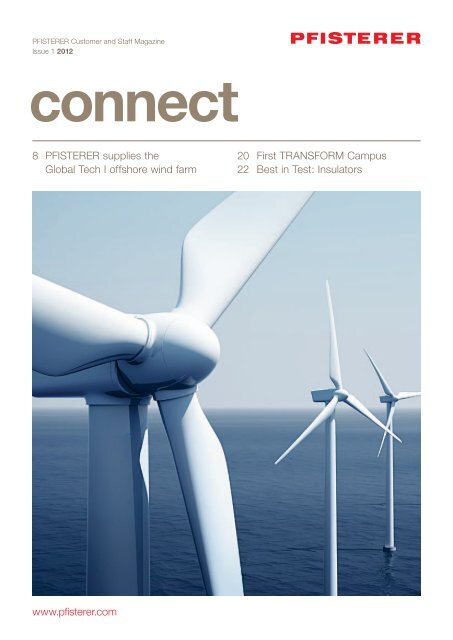
PFISTERER Customer and Staff Magazine<br />
Issue 1 2012<br />
8 PFISTERER supplies the<br />
Global Tech I offshore wind farm<br />
www.<strong>pfisterer</strong>.com<br />
20 First TRANSFORM Campus<br />
22 Best in Test: Insulators
Legal Notice<br />
Publisher<br />
PFISTERER Kontaktsysteme GmbH<br />
Rosenstraße 44<br />
73650 Winterbach<br />
Germany<br />
Tel: +49 7181 7005 0<br />
Fax: +49 7181 7005 565<br />
info@<strong>pfisterer</strong>.com<br />
www.<strong>pfisterer</strong>.com<br />
Editorial Team:<br />
Reto Aeschbach, Peter Arranz<br />
Paul Bausch, Günter Buschke<br />
Lutz Daul, Andreas Dobler<br />
Peter Feldhofer, Norbert Fink<br />
Sabrina Gratz, Ruben Grund<br />
Kurt Heinrich, Peter Kaiser<br />
Stephan Keller, Wadim Mirau<br />
Sven Müller, Martin Schuster<br />
Barbara Simeon, Radu Stancu<br />
Holger Stumpp, Matthias Wolf<br />
Lutz Zühlke<br />
Text Editor<br />
Karolina Kos<br />
www.xyzeiler.de<br />
Art Direction<br />
VISCHER & BERNET GmbH<br />
Marketing and Advertising Agency<br />
Stuttgart<br />
Cover picture<br />
fotolia / zentilia<br />
© Copyright by PFISTERER<br />
Kontaktsysteme GmbH<br />
PFISTERER<br />
Customer and<br />
Staff Magazine<br />
Issue 1 2012<br />
2 CONNECT 2012<br />
4 New organization for<br />
PFISTERER<br />
6 IXOSIL joints for Siemens<br />
project in Gera<br />
8 PFISTERER supplies the Global<br />
Tech I offshore wind farm<br />
12 Mechanical forces safely under<br />
control with HV-CONNEX<br />
14 Principles: Contact aging and<br />
effective remedies<br />
17 Practical tips for assembly with<br />
bolted connectors<br />
18 Award for innovative EST end<br />
closure<br />
20 TRANSFORM Campus: Unique<br />
transformer seminar<br />
22 Composite insulator strings<br />
successful in testing<br />
23 News
Editorial<br />
Innovations meet the challenges<br />
The challenges facing the energy<br />
industry are endless: Energy demand<br />
is increasing worldwide, power supply<br />
grids need to be renewed or extended,<br />
there is increasing use of renewable<br />
energy.<br />
If everything is in a state of flux, the best<br />
approach is to use applied knowledge<br />
in new ways. And this is PFISTERER’s<br />
way of doing things.<br />
Check out our project reports from<br />
page 8 onwards to find out how we use<br />
and optimize our proven technology in<br />
one of Germany’s first commercial<br />
offshore wind farms.<br />
In conditions of continuous growth, we<br />
need to remain flexible to meet a wide<br />
range of customer needs. That’s why<br />
we have put our group of companies on<br />
a new footing – see page 4.<br />
We would like to give you a better<br />
insight into the work we do for our<br />
clients across the world, with a redesigned<br />
CONNECT magazine that is<br />
more reader-friendly.<br />
We hope you find it a worthwhile read,<br />
giving you a new perspective on familiar<br />
challenges. We are ready to work with<br />
you to overcome them!<br />
Sincerely,<br />
Hr. Klein<br />
CEO, PFISTERER GmbH<br />
CONNECT 2012<br />
3
Strong growth and the changes in<br />
the energy market have transformed<br />
the PFISTERER Group in recent<br />
years. We have now reorganized the<br />
group so that we can continue to<br />
deliver efficiency to our customers.<br />
The PFISTERER Group started out as a consortium of<br />
independent companies. In 2005, their activities were<br />
strategically brought together in four centers of excellence,<br />
each with worldwide responsibility for the product groups<br />
assigned to them, and a global sales network was established.<br />
This partial centralization, product-oriented in its<br />
nature, achieved its goal of improving cooperation between<br />
the companies and brought about cross-border synergies.<br />
Since then, sales have more than doubled, the number<br />
of sales locations increased by over 70 percent and the<br />
number of employees worldwide by almost 40 percent.<br />
Thus in a short period of time, the group outgrew the<br />
recently established structures that had supported its<br />
tremendous growth.<br />
The markets were changing at the same time. More and<br />
more suppliers were adopting dry pluggable cable connection<br />
systems, a technology pioneered by PFISTERER and<br />
one in which the company has a leading position today.<br />
Increasingly, cable manufacturers are selling cable<br />
accessories without the cable itself. In the overhead line<br />
sector, insulators supplied from the Far East gained<br />
increasing acceptance, even at higher voltages. The<br />
increasing competition in established business areas<br />
mean that there is a greater need for application-specific<br />
solutions and the provision of an integrated customer<br />
service. Emerging markets, such as renewable energy,<br />
require innovative, cross-product solutions.<br />
PFISTERER:<br />
A new organization<br />
for new markets<br />
4 CONNECT 2012
Centralization for differentiation<br />
“Looking at how we have developed and the changes in<br />
our markets, the reorganization was a logical step,” said<br />
Dr. Thomas Klein, CEO of PFISTERER Holding AG,<br />
“We can only secure what we have achieved and promote<br />
further growth by aligning our structures with the new<br />
circumstances.” In recent months, PFISTERER laid the<br />
foundations for this with the introduction of four major<br />
business segments in which the core functions are<br />
coordinated and harmonized centrally across companies<br />
and national borders.<br />
The Sales Division brings together all the sales activities<br />
of PFISTERER companies across the world with the aim<br />
of creating a customer service that is even more applicationoriented.<br />
The Technology Division includes all development<br />
departments, laboratories, prototyping and product<br />
management with priority being given to the rapid development<br />
of new products and product variants. The Operations<br />
Division is expanding the successful use of synergies<br />
across all manufacturing sites. The financing, controlling,<br />
accounting, IT, HR and other key tasks are brought together<br />
for all companies within the Finance Department.<br />
CEO Dr. Thomas Klein also sees this reorganization as one<br />
that positions the PFISTERER Group to meet tomorrow’s<br />
demands: “The focus of the new functional units also<br />
shows what we want to do for our customers, which is to<br />
bring new technologies to market more quickly and to even<br />
more finely differentiate our services according industry<br />
and application.”<br />
“Looking at how we have<br />
developed and the<br />
changes in the markets,<br />
the reorganization was a<br />
logical step.”<br />
Dr. Thomas Klein, CEO<br />
CONNECT 2012<br />
5
IXOSIL<br />
joints for<br />
Siemens.<br />
Waterproof<br />
housing.<br />
Easier<br />
installation.<br />
6 CONNECT 2012<br />
Easier installation thanks to<br />
modular IXOSIL joints with<br />
bayonet locking housings<br />
When equipping a new substation<br />
in Gera, Siemens decided to use<br />
PFISTERER connection technology.<br />
Six IXOSIL MSA123-DOMG joints<br />
are included in the delivery package<br />
for the 110 kV cables.<br />
The new Gera Süd substation in Thuringia is the final part<br />
of a larger project: The 30 kV medium-voltage level in<br />
the local power distribution network is to be left out in<br />
favor of the nationwide 110 kV mains voltage. For this,<br />
extensive cable lines were laid for the 110 kV grid and two<br />
new substations have already been built and connected,<br />
in Gera-Nord (1995 to 2007) and Gera-Mitte (1996 to 2005).<br />
The entire project will be completed by mid 2013, including,<br />
alongside the construction of the three substations,<br />
the laying of a total of twelve kilometers of 110 kV cable<br />
and 90 kilometers of medium voltage cable.<br />
The Gera Süd substation was built by Siemens as a turnkey<br />
project. For the 110 kV cabling required, the general contractor<br />
chose IXOSIL sets from PFISTERER, including the<br />
MSA123-DOMG slip-on joints. The consistently modular
concept of the joints with the easy to install bayonet housing<br />
was particularly impressive. So during assembly two<br />
sleeve elements are simply put together and rotated against<br />
each other until they click. The metallic clamping rings that<br />
were previously attached are no longer required at all, and<br />
pipes and flanges are no longer needed either.<br />
The solid implementation of transverse water tightness<br />
by using an additional copper housing in the interior<br />
of the joint was also popular. Unlike plastic housings, this<br />
prevents penetration by hydrogen, which can lead to<br />
corrosion and partial discharges as well. For this reason,<br />
cables wrapped with aluminum foil are used as in the<br />
telecommunications industry. The conical shape at both<br />
ends of the joint housing also ensures high resistance<br />
to mechanical shear loads, as can occur when there is<br />
soil subsidence for example.<br />
Applications and<br />
benefits of IXOSIL<br />
MSA slip-on joints<br />
The IXOSIL slip-on joints consist mainly of prefabricated<br />
silicone parts and are available in one-piece or three-piece<br />
versions. Both joints are available in several versions,<br />
which differ from each other as regards the screening, the<br />
water vapor barrier and the protective housing.<br />
Applications<br />
For joining copper or aluminum conductors<br />
With cable cross-sections of up to 2,500 mm 2<br />
and bonding sections of up to 630 mm 2<br />
As a one-piece design for voltages from<br />
72.5 to 300 kV / U m<br />
As a three-piece design for voltages from<br />
72.5 to 170 kV / U m<br />
Features & Benefits<br />
Simple and secure assembly thanks to slip-on<br />
technology and bayonet locking<br />
Waterproof for buried joints according to IEC<br />
Designed for use with various fillings<br />
Available in various designs according to customer<br />
requirements, such as glass fiber reinforced PP<br />
Maximum stability thanks to 6 mm wall thickness<br />
Lightweight, tough material<br />
CONNECT 2012<br />
7
Global Tech I is to be constructed in<br />
the North Sea shortly – one of the<br />
first commercial offshore wind farms<br />
in Germany. PFISTERER is demonstrating<br />
the breadth of their range of<br />
products in this mammoth project:<br />
As a contact technology specialist<br />
supplying technologies that are<br />
suitable for offshore, they have<br />
developed a heavy-duty HV-CONNEX<br />
special solution, laying a total of<br />
5,800 m of cable under difficult<br />
conditions.<br />
Until now, in Germany, wind energy has been produced<br />
almost exclusively on land. Starting this year, power<br />
will be generated on the high seas around 180 km off<br />
Bremerhaven and 138 km off Emden, in a northwesterly<br />
direction: At a water depth of 40 m, a substation and<br />
80 wind turbines will be installed over an area of 41 km 2 .<br />
Global Tech I will be completed in 2013. With 400 MW<br />
rated power the wind farm will then be mathematically<br />
capable of providing electricity for 445,000 households.<br />
The AREVA Wind M5000 wind turbine generators (WTG)<br />
are designed specifi cally for offshore wind projects. Their<br />
rotor hubs rise 92 meters above sea level, each rotor and<br />
its three blades having a diameter of 116 m and sweeping<br />
an area as large as a one and a half football fi elds. The<br />
tips of the blades reach a top speed of 320 km/h. The<br />
rotors start to turn at a wind speed as low as 4 m/s.<br />
The turbines reach their peak power output of 5 MW at<br />
an average wind speed of 12.5 m/s. In severe storms,<br />
with wind speeds of 90 km/h, they turn off automatically<br />
for safety reasons.<br />
Offshore wind farm:<br />
PFISTERER solutions –<br />
pioneering achievements<br />
8 CONNECT 2012
Image source: Areva Wind GmbH<br />
Substation in transport construction and after anchoring in its final position in the sea<br />
Image source: Overdick GmbH & Co. KG<br />
PLUG for marine power plants<br />
All 80 WTGs are equipped with the PFISTERER PLUG<br />
system. This provides secure cable connections for the<br />
three components that are essential for generating energy<br />
– the wind turbine generator to the inverter and the<br />
inverter to a 5 MW power transformer. PLUG has already<br />
demonstrated its reliability in the rail sector, even under<br />
harsh conditions. <strong>Here</strong> on the high seas, the connection<br />
system’s strengths are played to the full: Because they are<br />
plugged, there is no need to access the internal parts of<br />
the equipment when making connections. This meant that<br />
ABB Switzerland was able to assemble the plug sockets<br />
in their inverters at the factory and supply them ready<br />
to be connected up. PFISTERER supplied the cable side<br />
plug to Areva Wind.<br />
This is an enormous advantage, and not only for the initial<br />
installation: Offshore maintenance work is costly, and the<br />
ease of installation saves time and money. The fitters are<br />
protected in both cases, as the connection system is<br />
designed to be safe to touch. The WTG itself must be able<br />
to withstand winds, wave loading and water currents in a<br />
saline environment. No problem for the plug connections:<br />
They are vibration resistant and protected against the ingress<br />
of foreign bodies and water in accordance with IP68.<br />
Thanks to their uniquely high current carrying capacity<br />
up to 1,250 A, they form lasting high-performance interfaces<br />
between the different items of electrical equipment.<br />
From there, the electrical power follows its path to the<br />
next station in the center of the wind farm – the substation.<br />
With suction cans on the sea floor<br />
For this purpose, a new concept was developed using an<br />
alternative approach. Overdick GmbH & CO. KG, engineers<br />
specializing in offshore applications, designed a platform<br />
CONNECT 2012<br />
9
with an enclosed cabinet that houses all of the resources<br />
for the connection of the wind farm to the grid, and protects<br />
them against the corrosive saline atmosphere. As<br />
the anchoring of the platform does not require pile driving<br />
work, the substation can be installed in a very environmentally<br />
friendly manner and with a minimal use of offshore<br />
logistics: Offshore tugs bring the floating substation to its<br />
destination, where the four tubular steel legs located on<br />
the float are lowered to the sea bed with a temporary<br />
strand jack system. There are suction cans on the feet of<br />
the tubular steel legs with which the structure is securely<br />
anchored to the seabed. Finally the platform is raised<br />
to its final position about 20 m above sea level using<br />
the temporary strand jack system and permanently fixed<br />
in place.<br />
The substation forms the energy heart of the wind farm:<br />
<strong>Here</strong> the power generated by all 80 turbines is brought<br />
together via submarine cables. MV-CONNEX joints form<br />
the secure interface to four 33 kV switchgear units. These<br />
distribute the incoming load to four power transformers<br />
that raise the voltage to 155 kV for transmission. To prevent<br />
shutdowns, multiple redundancy is built into these<br />
components.<br />
Behind the transformers is a gas-insulated switchgear unit.<br />
It distributes the power to two submarine cable systems.<br />
To protect against corrosion and abrasion, the submarine<br />
cables have particularly robust sheathing and are laid<br />
approximately 1.5 m in the seabed using a remotely controlled<br />
underwater vehicle. Laid in different routes, they will<br />
transmit the power in a southwesterly direction to the<br />
“BorWin Beta” converter platform. From there, the power is<br />
transmitted over a 195 km long high voltage direct current<br />
(HVDC) transmission link to the mainland to the transformer<br />
station hall in Lower Saxony, once again transformed and<br />
fed into the German grid. As one of the few offshore wind<br />
farms, Global Tech I already has an unconditional grid<br />
connection commitment.<br />
10 CONNECT 2012<br />
Seaworthy interface: MV-CONNEX joints can be<br />
mounted horizontally and vertically<br />
Complex cable-laying for CONNEX connectors<br />
PFISTERER supplied the CONNEX dry plug-connection<br />
system for cable connections between the switchgear<br />
and transformers at the substation. In 2010, CONNEX<br />
was the first complete system certified by German Lloyd<br />
for offshore use. PFISTERER developed the HV-CONNEX<br />
compensation clamp to be used for the first time in<br />
Global Tech I: It ensures the correct mechanical fixing of<br />
the cable with respect to the contacts and insulation of<br />
the HV-CONNEX system even under special installation<br />
and environmental conditions (for further details, see the<br />
report on page 12).<br />
A total of 5,800 m cable is attached to the CONNEX<br />
connectors, laid in the Rotterdam Dry Dock belonging to<br />
offshore business Keppel Verolme by a 14-man team<br />
from PFISTERER, including experts in cable laying work<br />
on oil rigs. A highly demanding task: In conventional<br />
cabling projects, 2,000m of cables can easily be laid<br />
every day, whereas here a maximum of only 120 m per<br />
day was possible. The complicated routing of the cable<br />
around a number of corners and over several decks<br />
required an immense effort in planning and organization.<br />
About 300 employees from various companies were working<br />
in various trades in parallel, in a confined space and<br />
to extremely high safety standards. So the PFISTERER<br />
professionals had to carry out the high voltage testing at<br />
night at weekends, as only then is the platform, which<br />
is still under construction, largely deserted. Nevertheless,<br />
the schedule was met, right down to the day: After<br />
13 weeks of working under pressure, PFISTERER passed<br />
over the successfully tested cable system on 31 July.<br />
PFISTERER special solutions for Global Tech I: Compact<br />
compensation clamps for HV-CONNEX cable connectors<br />
on the switchgear unit on the offshore transformer station
Global Tech I: The construction site at sea<br />
Constructors and operators of the wind farm: Global Tech I Offshore Wind GmbH<br />
Scope of project: 80 Areva Wind M5000 (5 MW) wind turbines, 1 transformer station (400 MW)<br />
Participating companies (excerpt):<br />
Wind turbine generators (WTG)<br />
Manufacturer: AREVA Wind GmbH,<br />
Connector technology: PFISTERER<br />
WTG foundations:<br />
Manufacturer: ARGE Tripod Global<br />
Tech I (consortium of WeserWind<br />
GmbH, Offshore Construction<br />
Georgsmarienhütte and Erndtebrücker<br />
Eisenwerk GmbH & Co. KG) and SIAG<br />
Nordseewerke GmbH<br />
Installation: HOCHTIEF Solutions AG<br />
Substation<br />
Manufacturer: Alstom Grid GmbH and<br />
Keppel Verolme BV<br />
Medium and high voltage cable and<br />
connection technology: PFISTERER<br />
Wind farm – internal wiring<br />
Manufacture, supply and install:<br />
Consortium of Norddeutsche<br />
Seekabelwerke GmbH and Global<br />
Marine Systems Ltd.<br />
PFISTERER special solutions for Global Tech I:<br />
Wind Turbines<br />
Delivery:<br />
4160 Plug connector systems<br />
Size 3 (male + female)<br />
Substation<br />
Cable installation<br />
650 m HV cable 800 mm 2<br />
1,400 m HV cable 500 mm 2<br />
2,900 m HV cable 400 mm 2<br />
850 m HV cable 150 mm 2<br />
Delivery and assembly:<br />
244 MV-CONNEX plugs size 3<br />
172 MV-CONNEX sockets size 3<br />
36 MV-CONNEX joints size 3<br />
44 HV-CONNEX plugs size 6<br />
44 HV-CONNEX sockets size 6<br />
HV cable systems from one source – PFISTERER<br />
Scope<br />
Projection, calculation, sizing, supply,<br />
installation and commissioning<br />
of high voltage cable systems with<br />
XLPE cables up to 245 kV<br />
Commissioning<br />
Acceptance testing (AC) with IPH<br />
Berlin, KEMA, EnBW<br />
Engineering<br />
Quotation processing<br />
Load calculations<br />
Routing<br />
Project management including<br />
commissioning<br />
Final documentation<br />
After-sales customer service<br />
Products<br />
CONNEX IXOSIL accessories<br />
up to 245 kV<br />
XLPE cables to 400 kV, conductor<br />
cross section to 2,500 mm 2 , jacket<br />
(copper wire, copper and Aluwell<br />
sheath; lead sheath)<br />
Cable Laying<br />
Only with businesses that are<br />
known and proven in the market<br />
Grid connection<br />
Network operator: TenneT TSO GmbH<br />
Testing:<br />
Acceptance tests for HV and MV<br />
cable connections on the platform<br />
Assembly<br />
With own staff (in each case<br />
in cooperation with qualified<br />
installation companies)<br />
Construction management<br />
Supervision<br />
Demo installations<br />
Training<br />
CONNECT 2012<br />
11
HV-CONNEX:<br />
Mechanical forces<br />
safely under control<br />
Forming a reliable interface between<br />
the plant and the high voltage<br />
cables, HV-CONNEX cable connectors<br />
fulfill important mechanical<br />
requirements in addition to their<br />
electrical functions. Mechanical<br />
forces are operating on each cable<br />
connection, and these must be<br />
compensated. PFISTERER has developed<br />
a compact clamp for particularly<br />
demanding applications such<br />
as offshore platforms.<br />
In operation, each cable expands due to heating. CONNEX<br />
compensates for this movement, which is in the range of<br />
several millimeters, because its contact cone is designed<br />
with a special shape that acts as a sliding bearing (Graphic,<br />
Point A). Furthermore the weight of the cable and the plug<br />
position act on the connection. The larger the cable crosssection,<br />
the greater the forces that act in an amplified way<br />
in a vertical cable position.<br />
The potential point of action of the weight is the bell flange<br />
of the CONNEX cable connector. <strong>Here</strong> there is a spring<br />
which presses the insulator of the cable connector into<br />
the CONNEX socket on the equipment side. If the weight<br />
of the cable works against this spring, the optimal contact<br />
force would not be achieved. This prevents an integrated<br />
system in the bell flange (Graphic, Point B): It centers and<br />
fixes the cable using a double cone with a bayonet lock<br />
and compression provided by an EPDM ring.<br />
12 CONNECT 2012<br />
Clamps operate against lateral forces<br />
To absorb the lateral forces caused by moving cables, the<br />
clamps also fix the cable to steel frames. The first clamp<br />
next to the equipment forms the third relevant mechanical<br />
area (Graphic, Point C). It should be centrally positioned<br />
with respect to the cable runs and be fixed at a maximum<br />
distance of 800 mm from the bell flange. Not every type<br />
of installation allows this. Or the mechanical system is<br />
canceled.<br />
On offshore platforms in particular, the transformers are<br />
often mounted on floating bearings because of their natural<br />
vibration, while the cable rack and the first clamp are<br />
removed further away to a relatively rigid base. This results<br />
in opposing cable movements that multiply the load on the<br />
connector. To deal with such situations safely, PFISTERER<br />
developed an additional compensation clamp (Graphics<br />
Point D), which was first used in the Global Tech I offshore<br />
wind farm.<br />
Special solutions for special loads<br />
For example, at a maximum lateral force of 1,500 N and<br />
at a distance of 800 mm from the equipment flange, the<br />
compensation clamp can limit the deflection of the cable<br />
to less than 20 mm. Without the compensating clamp this<br />
force would result in a deflection that was a factor of<br />
10 greater. Through the use of the clamp, the cable deflection<br />
that occurs at the HV-CONNEX connector is limited<br />
to acceptable values and the concentricity of the cable<br />
to the socket is maintained. Made of saltwater-resistant<br />
material, the compensation clamp is well prepared for the<br />
offshore industry.
PFISTERER solutions for offshore applications:<br />
Compact compensation clamps on HV-CONNEX cable plug on the power transformer<br />
A B D C<br />
The mechanical functional units A, B and C of the HV-CONNEX cable plug ensure the correct<br />
mechanical fi xing of the cable with respect to the contact and insulation of the system. D marks<br />
the additional compensation clamp for special operations such as on offshore platforms<br />
CONNECT 2012<br />
13
Contacts age. But they are designed<br />
to transmit power reliably<br />
for decades, across the innumerable<br />
interfaces within the energy<br />
network. This report shows how<br />
these requirements match up with<br />
the facts, covering the basics of<br />
contact technology and with a focus<br />
on the aging mechanisms operating<br />
in contacts and effective remedies<br />
to combat them.<br />
The initial resistance marks the beginning of aging in every<br />
contact. The higher this initial resistance is at the time a<br />
mechanical contact is manufactured, the shorter the life of<br />
the connection. Because electrical resistance grows with<br />
an increasing thermal load. Since almost all of the physical<br />
and chemical properties of materials are temperature<br />
dependent, at least to some degree, heat promotes aging<br />
in most materials.<br />
The effect of the initial resistance was examined as long<br />
ago as 1958 by J. A. Greenwood and J. B. P. Williamson<br />
in their paper on temperature-dependent conductors,<br />
(“Electrical Conduction in Solids. II Theory of Temperature-<br />
Dependent Conductors “, Royal Society Publishing):<br />
Where the initial resistance is 10 micro-ohms (μΩ), a<br />
mechanical connection can have a service life of up to a<br />
century, whilst at 100 μΩ it will be a maximum of fifty years.<br />
Why contacts age.<br />
And why they still<br />
last for decades.<br />
14 CONNECT 2012<br />
One connection. Two materials.<br />
It does not take much to cause the resistance to rise massively:<br />
For example, when a contact is operating in a tight<br />
cable trench, soil or other particles can contaminate the<br />
contact, or crimped contacts can suffer from the wrong<br />
combination of sleeve material and conductor material.<br />
When making a connection, aside from absolute cleanliness<br />
and a professional way of working, an understanding of<br />
the various conductor and connector materials is crucial.<br />
This is another important aspect, the effect of which<br />
extends far beyond limiting the initial resistance.<br />
The main materials used in the power supply industry are<br />
still copper and aluminum, although the recent rises in the<br />
price of copper together with the trend towards larger<br />
cable cross-sections are fueling the use of cheaper and<br />
lighter aluminum. So across the world, different conductor<br />
and connector materials are making contact with one<br />
another, for example, when a copper wire network is<br />
extended using aluminum conductors. This presents a<br />
challenge to the manufacturers of contacts, to produce a<br />
component which can be used with copper and aluminum<br />
conductors alike.<br />
PFISTERER Al Elast Contact Disks provide well defined<br />
contact surfaces.
The pitfalls of thermals<br />
The following classic installation error demonstrates how<br />
two materials thermally react in different ways. If an<br />
aluminum conductor is crimped into a copper sleeve, the<br />
premature failure of the contact is inevitable, even if the<br />
sleeve size is properly selected. Once electricity passes<br />
through the connection, it heats up and the aluminum<br />
conductor expands more than the copper sleeve can yield.<br />
As the electrical load increases, the mechanical stress<br />
between the conductor and the sleeve continues to rise,<br />
until it exceeds the yield strength of the aluminum – the<br />
conductor over-expands and no longer returns to its original<br />
shape upon cooling.<br />
After several heating and cooling cycles, the unwanted<br />
result is achieved – the minimum contact force is no longer<br />
reached and the electrical contact is degraded until there<br />
is total failure. The only remedy with crimping technology<br />
is the right combination of sleeve and conductor material,<br />
as shown in the table on page 16. The different coefficients<br />
of thermal expansion of copper and aluminum also<br />
demonstrate their effects where terminals are used. Often<br />
aluminum cables are connected to copper terminals.<br />
When heated, the conductor expands and returns to its<br />
original size on cooling. This process – called thermal<br />
breathing – can be equated with micro-movements by the<br />
conductor. The resulting aluminum abrasion debris oxidizes<br />
immediately and forms a non-conductive coating at the<br />
contact points, causing premature contact failure.<br />
Intelligent terminal designs such as Durelast terminals with<br />
U-bolts stop this movement by creating a suitably high<br />
contact force on the conductor – a technical trick used in<br />
the rail industry: As a result of heating, rails expand in a<br />
longitudinal direction. The resulting forces are directed into<br />
the ground, and thus compensated for, by the strong clamping<br />
forces generated by the ties mounted at short intervals.<br />
2DIREKT screw with a spring action thanks to the dished washer in use on a transformer<br />
Flow. Recover. Force.<br />
The correct dosage of contact force is determined by the<br />
flow and recovery processes in the materials, which result<br />
in a natural reduction in the clamping force. The contact<br />
force in any pair of mechanically connected materials<br />
reduces over time – or more precisely, by twenty to thirty<br />
percent just a few minutes after the initial installation.<br />
Nevertheless, it is possible to produce contacts that have<br />
a life span of ten to fifty years.<br />
Understanding contact hysteresis provides an approach<br />
to solving the problem. It takes more force to make a<br />
contact than to maintain it. This means that the functioning<br />
of a contact is only at risk if the remaining contact<br />
force falls below a minimum value of, for example, thirty<br />
percent of the initial force.<br />
For this not to occur during its entire service life, despite<br />
flow, recovery and thermal breathing, elasticity has to<br />
be structurally designed into the body of the clamp, for<br />
example in the form of springy, permanently elastic contact<br />
elements. Another remedy is to introduce additional<br />
elasticity by using springy washers. In the case of a screw<br />
connection for example, these are positioned between<br />
the screw head and the washer, which in turn rests on<br />
the rail to be connected.<br />
Water. Electricity. Corrosion.<br />
Electrolytic corrosion is another effect that drives contact<br />
aging where copper and aluminum are used in combination.<br />
Because of their molecular structure, the two metals<br />
have different potentials in relation to the neutral state: At<br />
−1.66 volts (V) aluminum is significantly more electronegative,<br />
while on the other hand copper is slightly electropositive<br />
at +0.34 V.<br />
If the metals touch, and a conductive medium such as<br />
water is presentat the point of contact, they act as a<br />
cathode and an anode: The potential difference of the<br />
two metals is 2 V, and depending on the conductivity<br />
of the electrolyte, this drives a weak flow of current that<br />
corrodes the more electronegative metal. The aluminum<br />
becomes pitted, contact points disappear and the<br />
CONNECT 2012<br />
15
emaining contact area is undermined. To prevent this, the<br />
design should separate different metals from one another<br />
in situations where they could come into contact with an<br />
electrolyte.<br />
<strong>Here</strong>, a brush stroke of insulating resin just few millimeters<br />
wide at the junction of the two materials is sufficient, as<br />
the – 2 V voltage cannot generate a current even over this<br />
short strip of insulation. Another insulation method is to<br />
inject small plastic parts. For connecting planar surfaces of<br />
aluminum with ones made of aluminum, copper or bronze,<br />
PFISTERER has developed the Al Elast Contact Disks.<br />
Three aging effects. One solution.<br />
These are positioned between the connection surfaces<br />
on the contact screw. During assembly, their concentric<br />
annular cutting edges penetrate through the the oxide<br />
layers on the connecting faces and create clean metallic<br />
contact surfaces. At the same time, the outer polyurethane<br />
elastomer sealing ring closes under compression,<br />
hermetically sealing the contact point o that electrolytes<br />
can no longer penetrate.<br />
Each thermal expansion may accelerate the flow and<br />
recovery processes. These processes, together with<br />
vibration, trigger mechanical movements which promote<br />
the wear of material just as oxidation and corrosion do.<br />
And that is only part of the spectrum of negative synergies<br />
that contribute to even more aging mechanisms. Their<br />
interaction may be complex, but their negative effects are<br />
clear to see: high temperatures, increasing electrical<br />
resistance, decreasing contact force – all harbingers of<br />
contact failure.<br />
Protection against corrosion: PFISTERER Al Elast Contact<br />
Disks hermetically seal contact points<br />
16 CONNECT 2012<br />
Reliable under full load<br />
If nothing else, each terminal must be designed and used<br />
according to the expected loads. The higher the constant<br />
power load, the faster the component ages. More and<br />
more situations occur where connections have been in<br />
operation for 30 years, and are therefore already in an<br />
aged condition, but are now being placed under greater<br />
load due to the higher utilization of the grid as it transmits<br />
increasing power. This is especially true in areas where<br />
here is a high proportion of energy fed into the grid is from<br />
renewable sources, where often the networks are already<br />
at full capacity.<br />
Martin Schuster, an expert on contact technology and<br />
Senior Adviser at PFISTERER concludes: “Anyone who<br />
aims to create reliable connections over the long-term<br />
must consider the aging mechanisms that apply in their<br />
situation and, ideally, incorporate the lessons learned<br />
in their specifications.” Or put more simply: Order contact<br />
technology from manufacturers for whom aging is not<br />
a new problem, but have developed practical solutions to<br />
combat it – such as, for example PFISTERER.<br />
Crimping technology:<br />
The right combination.<br />
Permanently contacts.<br />
With crimped connections, the right combination of<br />
materials also decides whether the contact will have<br />
a long or short life span. The correct choice of sleeves<br />
and conductor material is indicated by the plus sign.<br />
The minus sign indicates a classic assembly error.<br />
Aluminum<br />
conductor<br />
Copper<br />
conductor<br />
Aluminum sleeve Copper sleeve<br />
+ −<br />
+ +
PRACTICAL TIP:<br />
Tightening screws only<br />
reinforces your beliefs<br />
Some errors persist. Such as the<br />
widespread assumption that<br />
the tightening screws promotes the<br />
longevity of contacts. Terminals<br />
with shear bolts prove otherwise:<br />
They are designed to eliminate<br />
the perceived need for tightening,<br />
and are used more and more. What<br />
actually matters when assembling<br />
a screw connection is that the<br />
contact functions reliably throughout<br />
its entire life, as shown by this<br />
practical tip.<br />
1. Besides choosing the right terminal and the right<br />
material for the conductor (for details, see Contact<br />
Technical Report on page 14 and 16), the cleanliness<br />
of the contact area is crucial. This is best cleaned with<br />
a wire brush.<br />
2. To protect the surface from re-oxidizing, treat with a<br />
contact protection paste – particularly with easily oxidized<br />
aluminum connectors. For a permanently reliable contact,<br />
the screw also has to be clean.<br />
3. It should also be greased so that the applied torque<br />
results in the right contact force. Since this important step<br />
is often overlooked, PFISTERER supplies screws already<br />
greased or with a special coating that provides the necessary<br />
lubrication in place of grease.<br />
Lastly, when tightening the screws, the specified torque<br />
must be applied – this can be found in the installation<br />
manual or is printed on the terminal.<br />
CONNECT 2012<br />
17
Innovation for users.<br />
Award for EST.<br />
PFISTERER has been awarded a<br />
“Golden Amper 2012” in recognition<br />
of the level of innovation demonstrated<br />
by the new EST termination<br />
at Amper, the International Trade<br />
Fair for Electrical Engineering, Electronics,<br />
Automation and Communication<br />
Technology. PFISTERER had<br />
another winner with the development<br />
of a project-specific insulated<br />
crossarm.<br />
Insulating oils reliably fulfill their purpose. At the same time,<br />
their use is associated with high labor costs and they<br />
pose a threat to the environment. Unlike the unique EST<br />
and ESF terminations from PFISTERER: Made of modular<br />
silicone parts that are simply inserted and glued together,<br />
they do not need any oil.<br />
The EST is designed for continuous operation at voltage<br />
levels from 72.5 to 170 kV and consists of a flexible ESF<br />
and an additional support element. It can be installed<br />
on an overhead line tower without a working platform:<br />
The EST is connected to the high voltage cable whilst<br />
still on the ground and is then pulled up onto the mast<br />
with the cable. Compared to conventional connectors,<br />
they quickly save a significant amount in installation costs,<br />
with the downtime on the overhead line reduced from<br />
weeks to days.<br />
18 CONNECT 2012<br />
One price. Two successes.<br />
The user benefits convinced the ten experts on the Amper<br />
jury of the level of innovation demonstrated by the EST.<br />
Accepting one of five “Golden Amper 2012” awards in the<br />
“Energetics” category at the official awards ceremony in<br />
Brno, Czech Republic, Peter Feldhofer, CEO of PFISTERER<br />
Vienna Ges.mbH, and Arash Advini, Country Manager for<br />
the Czech Republic and Slovakia at PFISTERER Vienna.<br />
“Of course every new development requires a commitment<br />
to innovation,” said Feldhofer, “However, what is decisive<br />
is the view taken by neutral experts. That’s why we are so<br />
pleased about this recognition.” Slovak company ELV from<br />
Senec was also delighted with a “Golden Amper”: It was<br />
awarded for a new tower design for a 400 kV compact line,<br />
which is impressive for its environmentally friendly aesthetics<br />
and reduced electromagnetic fields. PFISTERER<br />
contributed to this success with an insulated crossarm<br />
specifically developed and tested for this project. For the<br />
reasons mentioned, compact overhead line masts will be<br />
increasingly used in the future.<br />
Distinguished: Arash Advini (2nd from left) and Peter Feldhofer (3rd from left)<br />
at the presentation of the Golden Amper 2012
Winners: The EST 123 on the PFISTERER booth at Amper<br />
in Brno, Czech Republic (left)<br />
Innovative EST terminal n use on an overhead line (bottom)<br />
CONNECT 2012<br />
19
The first “TRANSFORM campus”<br />
attracted young professionals and<br />
transformer experts to Berlin on 26<br />
and 27 June: International experts<br />
and manufacturers in the supply<br />
and measurement industry spoke<br />
about the technology and the key<br />
components involved in power<br />
transformers, together with their<br />
importance for the implementation<br />
of alternative energy sources.<br />
“In a few years, European<br />
high-voltage grids will be<br />
totally different from today”<br />
Prof. Dr.-Ing. Stefan Tenbohlen, University of Stuttgart<br />
TRANSFORM Campus:<br />
Accumulated knowledge<br />
about transformers<br />
20 CONNECT 2012<br />
In a few years, European high-voltage grids will be totally<br />
different from today,” explained keynote speaker Prof.<br />
Dr.-Ing. Stefan Tenbohlen, Head of the Department of<br />
Power Transmission and High Voltage Technology at the<br />
University of Stuttgart, at the opening of the compact<br />
two-day seminar “TRANSFORM campus: All about Transformers”.<br />
The move to alternative energy sources places<br />
immense demands on the electricity highways of the<br />
future. It is not only the high-voltage lines that are of great<br />
importance, but also the power transformers that act as<br />
interfaces between distribution grids and voltage levels.<br />
Both new transformers and those already in use will have<br />
to make the transition into an uncertain future under conditions<br />
that are to some extent still unclear. What remains<br />
is the investment risk associated with this: The purchase<br />
cost of large power transformers comes to several million<br />
euros, and they will only produce the desired return<br />
on investment if decades of trouble-free operation can<br />
be guaranteed.<br />
Ergo: a solid understanding of the capabilities and limitations<br />
of these transformers and the interplay between<br />
their key components is absolutely essential for operators.<br />
It does not matter which manufacturer a transformer<br />
comes from, because it always consists of the same basic<br />
elements – the core, the windings, the insulation, the step<br />
switch or the bushings. The quality of these components<br />
and how they interact determines the quality of a power<br />
transformer, something to which the TRANSFORM network<br />
is committed.
From practical experience for practical use<br />
Quality cannot be achieved without a depth of knowledge.<br />
That is why holding the compact seminar, led by Prof.<br />
Dr.-Ing. Rethmeier Kai, Head of the Institute of Electrical<br />
Power Engineering at the University of Applied Sciences<br />
in Kiel, and Martin Schuster, Senior Advisor at PFISTERER,<br />
was a logical step for the partners of the TRANSFORM<br />
network. Young engineers, young professionals and everyone<br />
in the transformer sector should be able to expand or<br />
refresh their practical knowledge at a single event. The<br />
expertise was provided by experts from the supply industry<br />
and manufacturers of transformer metrology. In addition to<br />
Herr Tenbohlen, other experts such as Prof. Dr.-Ing. Claus<br />
Neumann (Amprion / formerly RWE), Dr.-Ing. Michael<br />
Schäfer (TransNetBW) and Dipl.-Ing. Karl-Heinz Haeger<br />
(Alstom Grid) took on a complete presentation of the<br />
numerous practical contributions.<br />
The conclusions of 70 participants from all over Europe:<br />
The transformer has never before been so explained so<br />
effectively and in an easy to understand way in any other<br />
seminar. This was feedback that was particularly pleasing<br />
for the TRANSFORM partners, because it is not just in<br />
transformer technologies that they aim for high efficiency.<br />
TRANSFORM: Europe’s<br />
premium manufacturer of<br />
high-quality transformers<br />
The TRANSFORM name represents a network of partners<br />
who are European manufacturers of materials and<br />
components for the transformer industry. Since 1998, the<br />
network has been organizing TRANSFORM, a bi-annual<br />
international conference, which has become a respected<br />
industry platform for the transfer of knowledge relating<br />
to power transformers and the opportunity for specialists<br />
to exchange ideas. The following companies are involed in<br />
the TRANSFORM network: GEA Renzmann & Grünewald<br />
GmbH, HSP Hochspannungsgeräte GmbH & Trench<br />
Bushing Group, KREMPEL-Group, LS Cable & Essex,<br />
Maschinenfabrik Reinhausen GmbH, HIGHVOLT Prüftechnik<br />
Dresden GmbH, Nynas AB, OMICRON electronics<br />
GmbH, PFISTERER, Röchling Engineering Plastics KG<br />
and ThyssenKrupp Electrical Steel.<br />
More information about the TRANSFORM network and its<br />
events can be found on the Internet at www.transform.net.<br />
CONNECT 2012<br />
21
Realistic computer simulations<br />
confirmed. Composite insulator<br />
strings offer safety advantages.<br />
This was demonstrated by the latest<br />
practical and simulated load distribution<br />
tests for TIWAG-Netz AG –<br />
with positive results on two fronts:<br />
The PFISTERER composite insulator<br />
strings proved their resilience in<br />
operation, while the in-house<br />
simulation program proved its<br />
external validity.<br />
Alongside the operational mechanical loading and exceptional<br />
loads, insulator strings must also take up the static<br />
and dynamic stresses that emerge when a string fails.<br />
With multiple strings, in such situations the load redistribution<br />
sometimes results in high dynamic tensile and transverse<br />
forces. When using long rod insulators, consideration<br />
must be given to additional bending stresses. Furthermore,<br />
there have been cases in which the broken porcelain long<br />
rod flew into the second porcelain long rod that was still<br />
providing support, and as a result of the impact the complete<br />
porcelain string broke. Unlike composite insulators:<br />
Due to the elastic composite material, in such incidents<br />
a damping effect occurs and the additional stresses on<br />
the overall chain are reduced accordingly.<br />
In early 2012, in connection with a new 220-kV project,<br />
TIWAG-Netz AG of Austria arranged for checks to be carried<br />
out by SAG, the German technical inspection agency,<br />
to check how a composite insulator string actually behaves<br />
in use when there is a load redistribution and what the<br />
actual loads are. To do this, dynamic load redistribution<br />
tests were conducted on double suspension and double<br />
tension sets supplied by PFISTERER, which gave positive<br />
results with regard to their load carrying capacity. In addition,<br />
the load redistribution in the double tension set was<br />
simulated in advance, using an FEM based program developed<br />
by PFISTERER SEFAG AG for such investigations.<br />
Best in test:<br />
Insulators<br />
22 CONNECT 2012<br />
The simulated maximum occurring forces were very close<br />
to the experimental values measured by SAG, with deviations<br />
of only 5 to 10 percent. Ergo: Although it will remain a<br />
challenge in the future to create a simulation that is identical<br />
to reality, It is already possible to simulate a load redistribution<br />
with relatively high accuracy. The main advantage<br />
of computer simulation, in addition to the calculation values<br />
it gives, is the huge reduction in costs in terms of material,<br />
time and money. Furthermore, not only can the FEM model<br />
determine the forces and strains but also other detailed<br />
mechanical values. Good reasons for PFISTERER to recommend<br />
this simulation facility to its customers.<br />
Load transfer test set for a double hanging string at the SAG technical<br />
inspection agency
News<br />
Easier reinsertion:<br />
CONNEX size 2 with<br />
rotating flange<br />
For easier reinsertion of the CONNEX cable connector parts,<br />
PFISTERER now offers size 2 with a rotating bell flange. The only<br />
exception: The bell flange on the oceangoing offshore version is<br />
still made of bronze to give higher corrosion resistance, which<br />
precludes offering a rotating version. The greater user-friendliness<br />
of all other new standard versions of the CONNEX cable connector<br />
Size 2 parts is impressive:<br />
The fixing screws can be easily rotated to the fit the position of<br />
the threaded bushings. This also makes it easier to reinsert after<br />
the initial installation, even for large cable cross sections, such<br />
as when inspecting transformers, using portable transformers<br />
or emergency generators that feed power into the medium<br />
voltage side. An additional earthing screw on the fixing flange<br />
allows for separate earthing, for example when it is not possible<br />
to make a potential connection using the threaded sockets or<br />
the equipment housing.<br />
Thick insulation?<br />
Compact connection!<br />
New CONNEX variant<br />
in size 2<br />
With the introduction of a new variant of the<br />
CONNEX cable connection system, size 2,<br />
PFISTERER is making arrangements for the trend<br />
towards thicker cable insulations, and the requirements<br />
for compact design in electrical equipment.<br />
The new version is designed for cable diameters<br />
over insulation up to 44 mm 2 , which can now be<br />
connected with cross-sections of 400 mm 2 (36 kV).<br />
An important advantage when connecting cables<br />
from Asian and North American manufacturers:<br />
These often have thicker insulation and therefore<br />
a greater overall cross section. The result is that<br />
larger, often oversized cable connection components<br />
are used that take up more space in the<br />
equipment. Unlike with newcomer PFISTERER:<br />
It permits high performance connections to be<br />
made to heavily insulated cables with the usual<br />
compact design of the CONNEX system size 2 –<br />
the ideal solution for the underground installation<br />
of substations in urban areas and wherever space<br />
is tight and the safety requirements high.<br />
CONNECT 2012<br />
23
Compact. Pluggable.<br />
HV-CONNEX<br />
surge arrester.<br />
Solid insulation<br />
Compact design<br />
Can be changed without gas or oil work in the<br />
GIS or transformer<br />
Interchangeable with all pluggable components<br />
from HV-CONNEX system size 4<br />
Voltages up to U m = 72.5 kV<br />
www.<strong>pfisterer</strong>.com THE POWER CONNECTION