Differential Relays - SIPROTEC
Differential Relays - SIPROTEC
Differential Relays - SIPROTEC

Create successful ePaper yourself
Turn your PDF publications into a flip-book with our unique Google optimized e-Paper software.
7SD503 Line differential protection with three pilot–wires<br />
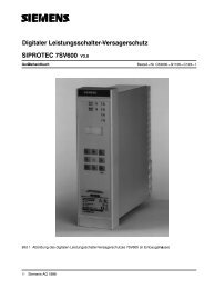
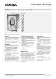
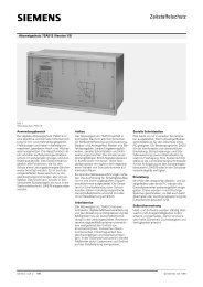
Fig. 1<br />
7SD503 line differential protection<br />
Application<br />
The 7SD503 line differential protection is<br />
a fast and selective differential protection<br />
unit for cables and overhead lines.<br />
It is the successor of the 7SD74 static<br />
differential protection and works with it if<br />
external pilot–wire monitoring is used.<br />
The connection between two 7SD503<br />
units is made via three pilot–wires, i.e.<br />
existing pilot–wire connections can be<br />
used.<br />
Design<br />
Within its compact dimensions the unit<br />
contains:<br />
� All components for measured–value<br />
acquisition and evaluation<br />
� Summation current transformer<br />
� Operation and display panel<br />
� Binary input options<br />
� Auxiliary voltage converter<br />
The unit can be supplied in two different<br />
housings. The one for flush mounting in a<br />
panel or cubicle has connections at the<br />
rear. The other for surface mounting on a<br />
panel has screw terminals accessible<br />
from the front.<br />
Scope of functions<br />
Method of operation<br />
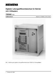
The summation current transformer integrated<br />
in the housing of the 7SD503 permits<br />
the connection of any secondary<br />
currents of the primary current transformer<br />
(see Fig. 2). The three primary<br />
windings of the summation current transformer<br />
have the winding ratio 2:1:3. With<br />
1 x �N as the three–phase, balanced<br />
short–circuit current, the secondary<br />
single–phase current �M1 of the summation<br />
current transformer is 100 mA. The<br />
summation current transformer principle<br />
gives different short–circuit sensitivities<br />
depending on the connection, e.g. different<br />
weightings can be assigned to the<br />
earth fault.<br />
The 7SD503 acquires the secondary pulsating<br />
current � M1 of the local station,<br />
that of the remote station � M2 and the<br />
sum of the pulsating currents as a differential<br />
� diff in the central pilot–wire. With<br />
three–end protection, the boosting current<br />
�boo is acquired at the third line end<br />
and included in the calculation.<br />
The line is shut down if the protection<br />
system finds that the differential current<br />
� diff indicates a short–circuit in the protection<br />
zone.<br />
Digital measured–value processing with<br />
consistent evaluation of the fundamental<br />
of the measured quantities largely eliminates<br />
the influence of high frequency<br />
transient phenomena, transient DC components<br />
and differing current transformer<br />
saturation.<br />
Features<br />
<strong>Differential</strong> <strong>Relays</strong><br />
� Selective short–circuit protection for<br />
overhead lines and cables<br />
� Acquisition of pulsating current behind<br />
the summation current transformer<br />
and of currents via the pair of pilot–<br />
wires<br />
� Sensitivity to single–phase faults under<br />
rated current<br />
� 100 % protection against all types of<br />
short–circuit within the protection zone<br />
� Circuit–breaker intertripping and remote<br />
tripping of the remote station<br />
� Optional integrated pilot–wire monitoring<br />
� Overload protection with thermal characteristic<br />
� Two–stage definite–time/inverse time<br />
overcurrent protection as standby with<br />
pulsating � M1<br />
� Real–time clock and permanently<br />
stored status and fault indications in<br />
the event of auxiliary voltage failure.<br />
Previous LSA interface (Siemens–specific)<br />
or VDEW/ZVEI interface with the<br />
substation control and protection.<br />
� Protection of three–end pilot–wires<br />
with two devices at each end of the<br />
line is possible.<br />
Siemens LSA 2.2.2 . March 1997 Siemens AG 1997 1<br />
49<br />
50<br />
51<br />
87<br />
�
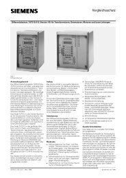
<strong>Differential</strong> <strong>Relays</strong><br />
2<br />
7SD503 Line differential protection with three pilot–wires<br />
Serial interfaces<br />
The device is equipped with two serial<br />
interfaces.<br />
The operating interface on the front panel<br />
is suitable for the connection of a<br />
WINDOWS capable PC. The DIGSI operating<br />
and analysis software allows easy<br />
setting, fault recording evaluation and<br />
commissioning. The system interface is<br />
an 820 nm fibre–optic interface for linking<br />
to the SINAUT LSA substation control<br />
and protection system or a protection<br />
master unit (protocol to VDEW/ZVEI<br />
recommendation). The operator with<br />
DIGSI can also be connected to the system<br />
interface.<br />
Parameter setting<br />
Using the integrated operating and display<br />
panel or a PC all parameter settings<br />
can be made under user guidance. The<br />
parameters are written to a non–volatile<br />
memory so that they are retained even<br />
after the supply voltage has been<br />
switched off.<br />
Self–monitoring<br />
The hardware and software are<br />
constantly monitored and irregularities<br />
are detected and signalled immediately.<br />
This considerably enhances safety, reliability<br />
and availability.<br />
<strong>Differential</strong> protection for lines and<br />
cables<br />
The differential protection of the 7SD503<br />
contains the following functions:<br />
� The summation current transformer<br />
principle makes the sensitivity dependent<br />
on the type of error. Single–phase<br />
errors are dealt with higher priority and<br />
weighted with higher sensitivity because<br />
of the dimensioning of the<br />
summation current transformer.<br />
� For differential protection, an overcurrent<br />
enable can be parameterized. The<br />
close/open commands of the differential<br />
protection are only given when a<br />
settable value for the pulsating current<br />
�M1 is exceeded.<br />
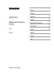
� Response characteristic for three–<br />
phase, balanced short–circuit current<br />
as shown in Fig. 3. The response value<br />
� diff> and the gradient of the characteristic<br />
branches are parameterizable.<br />
� High stability with different current<br />
transformer saturations during an external<br />
short–circuit because of the use<br />
of an integrated saturation detector.<br />
� Insensitive to DC components and<br />
high–frequency transient phenomena<br />
because the fundamental is filtered<br />
out of the measured quantities using<br />
digital filters.<br />
Fig. 2<br />
Connection principle 7SD503<br />
�diff<br />
�N<br />
L1<br />
4<br />
3<br />
2<br />
1<br />
L2<br />
L3<br />
Normalized<br />
differential current<br />
�Diff><br />
Fig. 3<br />
7SD503 line differential protection<br />
Summation<br />
current<br />
transformer<br />
Pilot–wire connection to remote station/pilot–wire<br />
monitoring<br />
The connection to the remote station is<br />
made using a balanced pair of wires (e.g.<br />
telephone wires). The pilot–wire connection<br />
is part of the differential protection.<br />
For this reason the pilot–wires are<br />
constantly monitored by a pilot–wire<br />
monitoring function integrated into the<br />
7SD503. To achieve this, 2 kHz pulses<br />
with a defined pulse width ratio are transmitted<br />
to the remote station via the pilot–<br />
wires. The pulse length and pulse level<br />
are evaluated using a filter processor so<br />
2<br />
1<br />
3<br />
7SD503<br />
m1<br />
7SD503<br />
IM1<br />
Tripping<br />
Measured currents<br />
Blocking<br />
IDiff<br />
1 2 3 4 5 �stab<br />
IM2<br />
Fault characteristic<br />
with single–end infeed<br />
m2<br />
Pilot–wire<br />
connection<br />
to the<br />
remote<br />
station<br />
Normalized<br />
stabilization current<br />
that any break in the pilot–wire is detected<br />
reliably. Both stations have the<br />
same priority and alternate between<br />
functioning as a sender and receiver.<br />
If 7SD503 and, e.g., 7SD74 are to be<br />
used together, external pilot–wire monitoring<br />
is required. Circuit–breaker intertripping<br />
and remote tripping are then no<br />
longer available.<br />
�N<br />
Siemens LSA 2.2.2 . March 1997
7SD503 Line differential protection with three pilot–wires<br />
Circuit–breaker intertripping and remote<br />
tripping<br />
It is possible to open the circuit–breaker<br />
at the other end if the infeed conditions<br />
at that end are weak. Remote tripping<br />
can also be initiated by a circuit–breaker<br />
standby protection relay or transformer<br />
differential protection relay linked via a<br />
binary input.<br />
For both functions the integrated pilot–<br />
wire monitoring function is required. It<br />
works in both directions, but not at the<br />
same time.<br />
Thermal overload protection<br />
Thermal overload protection with a pre–<br />
warning stage is integrated for the thermal<br />
protection of cables. It functions with<br />
pulsating current acquired behind the<br />
summation current transformer. This pulsating<br />
current is an image of the three–<br />
phase balanced load in normal or overload<br />
operation.<br />
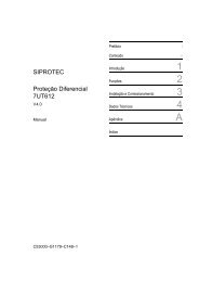
The tripping time characteristics (see<br />
Fig. 4) are exponential functions to IEC<br />
255–8 and they take account of heat loss<br />
due to the service current and the accompanying<br />
drop in temperature of the<br />
cooling medium. The previous load is<br />
therefore taken into account in the tripping<br />
time on overload. A settable warning<br />
stage can output a current or temperature–dependent<br />
indication before the tripping<br />
point is reached.<br />
Standby overcurrent–time protection<br />
An overcurrent–time protection is used<br />
as standby protection with a choice of<br />
definite–time or inverse–time characteristics.<br />
The protection has two stages, i.e.<br />
an overcurrent stage (�>) and a high current<br />
stage (�>>). The high current stage<br />
always has a definite–time characteristic.<br />
Both stages can be disabled via a binary<br />
input. The response value of the standby<br />
protection is derived from the pulsating<br />
quantity so that there are different response<br />
values depending on the fault.<br />
Fault recording<br />
The digital measured values of the pulsating<br />
current of the local station, of the<br />
remote station, and of the second remote<br />
station in a three–ended pilot–wire<br />
scheme are stored along with the differential<br />
and stabilization current in the<br />
event of a fault. The current progressions<br />
can either be directly transferred to a PC<br />
or read out by the SINAUT LSA station<br />
control system. If the VDEW/ZVEI interface<br />
to the control system is used, up to<br />
eight fault recordings are stored. The<br />
fault recording buffer is a circulating<br />
buffer with a maximum length so that the<br />
oldest fault recordings are overwritten if<br />
a further network fault occurs after the<br />
buffer is full.<br />
t (min) Parameter:<br />
t (min)<br />
set value<br />
100<br />
time constant � (min) 100<br />
50<br />
Fig. 4<br />
Tripping time characteristics of the overload protection function<br />
Indications<br />
The 7SD503 unit provides detailed data<br />
for the analysis of faults and for checking<br />
statuses. All the following indications are<br />
backed up against supply voltage failure.<br />
� Clock time<br />
As a standard a battery–backed clock<br />
is used that can be synchronized via a<br />
binary input or the system interface. A<br />
date and time is assigned to all indications.<br />
� Fault indications<br />
Fault indications are available for faults<br />
stored in the unit.<br />
� Status indication<br />
All indications that are not directly related<br />
to a fault are stored in the status<br />
indication buffer.<br />
<strong>Differential</strong> <strong>Relays</strong><br />
20<br />
20<br />
1000<br />
10<br />
10<br />
500<br />
5<br />
5<br />
3<br />
3<br />
1000<br />
2<br />
100<br />
2<br />
500<br />
1<br />
50<br />
1<br />
0.5<br />
0.5<br />
0.3<br />
0.3<br />
100<br />
0.2<br />
0.2<br />
10<br />
50<br />
0.1<br />
5<br />
0.1<br />
0.05<br />
0.05<br />
0.03<br />
1<br />
1 2 3 4 5 8 10 �M1<br />
k · �N<br />
without previous load<br />
5<br />
1 10<br />
0.03<br />
1 2<br />
3 4 5 8 10 �M1<br />
k · �N<br />
with 90 % previous load<br />
Marshallable command and alarm<br />
relay, LEDs, binary inputs<br />
All input/output relays including the LEDs<br />
are user–specific and can be marshalled<br />
independently. Several events can be programmed<br />
simultaneously on one input/<br />
output relay.<br />
Commissioning<br />
The following commissioning aids are<br />
provided:<br />
� Display of pulsating currents the differential<br />
and stabilization current with absolute<br />
value and phase.<br />
� Software–controlled level alignment of<br />
the pilot–wire monitoring function and<br />
testing of the circuit–breaker intertripping<br />
and remote tripping command<br />
functions.<br />
Siemens LSA 2.2.2 . March 1997 3<br />
50<br />
Parameter:<br />
set value<br />
time constant � (min)
<strong>Differential</strong> <strong>Relays</strong><br />
Technical data<br />
Input circuits Rated current �N<br />
Rated frequency fN, settable<br />
Maximum load of current inputs thermal continuous<br />
�10 s<br />
� 1s<br />
dynamic half–wave<br />
Auxiliary DC voltage Rated auxiliary voltage Vaux<br />
4<br />
7SD503 Line differential protection with three pilot–wires<br />
Binary inputs Marshallable 7SD503<br />
DC operating voltage<br />
Current consumption<br />
Permissible range of the rated auxiliary voltage<br />
Permissible maximum ripple at rated auxiliary voltage<br />
Power consumption not energized<br />
energized<br />
Stored energy time at Vaux �110 V<br />
Alarm contacts Number of alarm relays 7SD503 marshallable<br />
Contacts per relay<br />
Making/breaking power<br />
Switching voltage<br />
Permissible current<br />
Command contacts Number of tripping relays 7SD503 marshallable<br />
Contacts per relay<br />
Making power<br />
Breaking power<br />
Switching voltage<br />
Permissible current continuous<br />
0.5 s<br />
LEDs Ready display green<br />
Fault display red<br />
Marshallable LEDs 7SD503 red<br />
Design Housing, dimensions<br />
Terminals Panel/cabinet flush mounting<br />
Panel surface mounting<br />
Degree of protection to EN 60 529<br />
Serial interfaces Operating interface V.24 (RS232C)<br />
System interface<br />
Protocol<br />
Safety<br />
Transmission rate<br />
Method<br />
Connection of fibre–optic cables<br />
Optical wavelength<br />
Permissible path attenuation<br />
Distance<br />
CE–conformity, standards This product is in conformity with the directives of the Council of<br />
the European Communities on the approximation of the laws of<br />
the Member States relating to the electromagnetic compatibility<br />
(EMC Council Directive 89/336/EEC) and concerning electrical<br />
equipment for use within specified voltage limits (low–voltage<br />
directive 73/23/EEC). The product conforms with the international<br />
standard IEC 255 and the national standard DIN 57 435 part 303<br />
(corresponding to VDE 0435 part 303).<br />
The relay is designed for use in an industrial environment, for<br />
installation in standard relay rooms and compartments so that<br />
with proper installation electro–magnetic compatibility (EMC) is<br />
ensured.<br />
1 or 5 A<br />
50 or 60 Hz<br />
4 x �N<br />
20 x �N<br />
100 x �N<br />
250 x �N<br />
24, 48 V or<br />
60, 110, 125 V or<br />
220, 250 V<br />
19 to 56 V<br />
48 to 144 V<br />
176 to 288 V<br />
�12 %<br />
approx. 9 W<br />
approx. 10.5 W<br />
�50 ms<br />
2/4 with/without pilot–wire monitoring<br />
24 to 250 V<br />
approx. 2.5 mA<br />
5<br />
See connection diagram<br />
20 W/VA<br />
250 V AC/DC<br />
1 A<br />
2/4 with/without pilot–wire monitoring<br />
See dimension drawing<br />
1000 W/VA<br />
30 W/VA<br />
250 V AC/DC<br />
5 A<br />
30 A<br />
1<br />
1<br />
6<br />
7XP20, see dimension drawings<br />
Crimp connections<br />
Two–tier screw terminals<br />
IP51<br />
Front connector, not isolated, 25–pin,<br />
suitable for connection of a PC<br />
Isolated optical 820 nm interface, for connecting<br />
to a central unit<br />
Siemens–specific or acc. to VDEW/ZVEI<br />
recommendation<br />
Hamming distance d = 4<br />
4800, 9600 or 19000 Bd<br />
Serial, asynchronous<br />
Two integrated FSMA plug connectors for<br />
fibre–optic connection<br />
820 nm<br />
max. 8 dB with glass fibre 62.5/125 �m<br />
max. 1.5 km at 3 dB system reserve<br />
Conformity is proved by tests performed<br />
by Siemens AG in line with article 10 of the<br />
Council Directives in accordance with the<br />
generic standards EN 50081 and EN 50082<br />
for the EMC directive 89/336/EEC and<br />
standard 60255–6 for the low–voltage directive.<br />
Siemens LSA 2.2.2 . March 1997
7SD503 Line differential protection with three pilot–wires<br />
Technical data (continued)<br />
Insulation tests<br />
IEC 255–5, DIN 57 435 part 303<br />
EMC–tests; immunity (type test)<br />
Standards: IEC 255–6, IEC 255–22<br />
(international product standard)<br />
EN 50082–2 (generic standard)<br />
VDE 0435 part 303 (German<br />
product standard)<br />
EMC–tests; emission (type test)<br />
Standard: EN 50081–* (European generic<br />
standard)<br />
High–voltage test (routine test), except d.c. voltage supply input<br />
High–voltage test (routine test), only d.c. voltage supply input<br />
Impulse voltage test (type test), all circuits, class III<br />
High frequency test with 1 MHz interference<br />
IEC 255–22–1, class III and VDE 0435 part 303, class III<br />
Electrostatic discharge<br />
IEC 255–22–2, class III and IEC 1000–4–2, class III<br />
Radio–frequency electromagnetic field, non–modulated<br />
report IEC 255–22–3, class III<br />
Radio–frequency electromagnetic field, amplitude modulated<br />
IEC 1000–4–3, class III<br />
Radio–frequency electromagnetic field, puls modulated<br />
ENV 50204, class III<br />
Fast transients<br />
IEC 255–22–4 class III, IEC 1000–4–4 class III<br />
Conducted disturbances induced by radio–frequency fields,<br />
amplitude modulated<br />
IEC 1000–4–6, class III<br />
Power frequency magnetic field<br />
IEC 1000–4–8, class IV<br />
IEC 255–6<br />
Conducted interference voltage, auxiliary voltage<br />
CISPR 22, EN 55022 and VDE 0878 part 22<br />
Interference field strength<br />
CISPR 11, EN 55011 and VDE 0875 part 11<br />
Climatic stress tests Permissible ambient temperature during service<br />
during storage<br />
during transport<br />
Permissible humidity<br />
Mechanical stress tests<br />
IEC 255–21–1, IEC 68–2<br />
Permissible mechanical stress during service<br />
during transport<br />
Current differential protection Setting ranges response value �diff>/�N<br />
Times<br />
Response times (double–end infeed)<br />
at � = 4 x set value �diff>/�N<br />
at � = 10 x set value �diff>/�N<br />
Additional time delay of the tripping command<br />
Minimum command duration<br />
Release value �diff>/�N<br />
Tolerance of the response characteristics (stationary, single–end<br />
infeed)<br />
Frequency range fN = 50 Hz<br />
fN = 60 Hz<br />
Overload protection Setting ranges<br />
Factor k to IEC 255.8 Step 0.01<br />
Time constant � Step 0.1 min<br />
Temperature warning stage �alarm/�trip<br />
Current warning stage �alarm<br />
Tripping temp.<br />
Tripping time characteristic<br />
Release conditions<br />
Tolerances<br />
<strong>Differential</strong> <strong>Relays</strong><br />
2 kV (rms), 50 Hz<br />
2.8 kV DC<br />
5 kV (peak), 1.2/50 �s, 0.5 J,<br />
3 positive and 3 negative shots at intervals<br />
of 5 s<br />
2.5 kV (peak), 1 MHz, � = 15 �s,<br />
400 shots/s, duration 2 s<br />
4 / 6 kV contact discharge, 8 kV air discharge,<br />
both polarities, 150 pF, Rl = 330 �<br />
10 V/m, 27 to 500 MHz<br />
10 V/m, 80 to 1 000 MHz, AM 80 %, 1 kHz,<br />
10 V/m, 900 MHz, repetition frequency<br />
200 Hz, duty cycle 50 %<br />
2 kV, 5/50 ns, 5 kHz, burst length = 15 ms,<br />
repetition rate 300 ms, both polarities,<br />
Rl = 50 �� duration 1 min<br />
10 V, 150 kHz to 80 MHz, AM 80 %, 1 kHz,<br />
30 A /m, continuous, 300 A /m for 3 s, 50 Hz<br />
0.5 mT; 50 Hz<br />
150 kHz to 30 MHz, class B<br />
30 to 1 000 MHz, class A<br />
–5 to +55 °C<br />
–25 to +55 °C<br />
–25 to +70 °C<br />
mean value per year �75 % relative humidity,<br />
on 30 days per year up to 95 % relative<br />
humidity, condensation not permissible<br />
10 to 60 Hz, 0,035 mm amplitude<br />
60 to 500 Hz, 0,5 g acceleration<br />
5 to 8 Hz, 7,5 mm amplitude<br />
8 to 500 Hz, 2 g acceleration<br />
0.5 to 2.5 (in steps of 0.01)<br />
approx. 23 to 33 ms<br />
approx. 16 to 26 ms<br />
0 to 60 s (step 0.01 s)<br />
0.05 to 32 s (step 0.01 s)<br />
approx. 0.9 x set value<br />
�3 % of the set value + 0.5 % /km pilot–<br />
wire<br />
45 to 55 Hz<br />
55 to 65 Hz<br />
1 to 5<br />
1 to 999.9 min<br />
50 to 100 %<br />
�alarm � �max = k � �N<br />
t � �Ig<br />
� 2 – � 2 pre<br />
� 2 –(k�� N ) 2<br />
�/�alarm approx. 0.99<br />
�/�trip approx. 0.99<br />
�/�alarm approx. 0.97<br />
Class 10 % to IEC<br />
Maximum pilot–wire resistance, Permissible range for the resistance of a pilot–wire 200 � per wire<br />
Pilot–wire monitoring Pulse–code modulated 2 kHz send current<br />
Max. send level<br />
Min. receive level<br />
8 mA = 100 %<br />
0.1 mA<br />
Siemens LSA 2.2.2 . March 1997 5
<strong>Differential</strong> <strong>Relays</strong><br />
Technical data (continued)<br />
Setting ranges<br />
Overcurrent protection definite–time<br />
6<br />
7SD503 Line differential protection with three pilot–wires<br />
Overcurrent pulsating current �M1><br />
High current pulsating current �M1>><br />
Delay times<br />
Tolerances<br />
Response value for current<br />
Timing interval<br />
Release time<br />
Overcurrent protection inverse–time Overcurrent pulsating current �M1><br />
Time multiplier tp<br />
Energizing threshold<br />
Characteristic to IEC 255–4, Section 3.5.2 or BS 142<br />
Linear measuring range<br />
Tolerances<br />
Energizing threshold<br />
Time interval<br />
Measurement Operating currents<br />
Measuring range<br />
Tolerances<br />
Overload protection values<br />
Winding temperature<br />
Measuring range<br />
Tolerances<br />
�M1/�N = 0.1 to 30<br />
�n1/�N = 0.1 to 30<br />
0 to 32 s or inactive<br />
�5 % from set value<br />
�1 % or �10 ms<br />
approx. 30 ms<br />
�p/�N = 0.1 to 20<br />
0.05 to 32 s<br />
1.06 x �p<br />
Normal, strong or extremely dependent<br />
40 x �N<br />
�5 %<br />
�5 % for 2 (�/�p>) �20<br />
and tp = 1 or 30 ms<br />
�M1, �M2, �M3, �diff, �stab<br />
0 to 240 % �N<br />
�2 % from rated value of the local station<br />
+ 0.5 % /km pilot–wire<br />
�/�trip calculated<br />
0 to 240 %<br />
�3 % with respect to �trip<br />
Fault logging Fault indication Storage of the last 8 faults<br />
Fault recording Line currents (instantaneous values)<br />
Time resolution of the instantaneous values<br />
Max. number of recordings<br />
Start signal<br />
�M1, �M2, �M3, �diff, �stab<br />
1.66 at fN = 50 Hz<br />
1.39 at fN = 60 Hz<br />
8 in 19 s recording buffer<br />
Energizing, PC/LSA operation, tripping,<br />
binary input<br />
Siemens LSA 2.2.2 . March 1997
7SD503 Line differential protection with three pilot–wires<br />
Selection and ordering data<br />
<strong>Differential</strong> <strong>Relays</strong><br />
Order No.<br />
7SD503 numerical three pilot–wire differential protection 7SD503 � – ��A 1 1 – 0�A 0<br />
Rated current at 50 to 60 Hz<br />
1 A<br />
5 A<br />
Rated auxiliary voltage<br />
24, 48 V DC<br />
60, 110, 125 V DC<br />
220, 250 V DC<br />
Construction<br />
Housing 7XP2040 for panel surface mounting<br />
Housing 7XP2040 for panel and cubicle flush mounting<br />
Housing 7XP2040 for panel and cubicle flush mounting (without glass cover)<br />
Integrated pilot–wire monitoring/CB intertripping<br />
with<br />
with<br />
Serial system interface<br />
without<br />
with integrated optical 820 nm module<br />
Operating program (German and English are standard, other languages on request)<br />
DIGSI program (suitable for all protection relays 7UM..., 7UT..., 7SJ..., 7SA..., ...) German<br />
English<br />
Test version: German<br />
English<br />
Connecting cables for protection relays (25-pin) – PC (9-pin); (other variations supplied on request)<br />
Documentation<br />
German: Katalogblatt LSA 2.2.2: Leitungsdifferentialschutz 7SD503 mit drei Hilfsadern<br />
Handbuch: Leitungsdifferentialschutz 7SD503 (V 3.0) mit drei Hilfsadern<br />
English: Catalog LSA 2.2.2: 7SD503 Line differential protection with three pilot–wires<br />
Manual: 7SD503 Line differential protection with three pilot–wires<br />
Siemens LSA 2.2.2 . March 1997 7<br />
1<br />
5<br />
2<br />
4<br />
5<br />
7XS5020–0AA00<br />
7XS5020–1AA00<br />
7XS5021–0AA00<br />
7XS5021–1AA00<br />
7XV5100–2<br />
B<br />
C<br />
E<br />
E50001–K5722–A121–A2<br />
C53000–G1100–C96–3<br />
E50001–K5722–A121–A2–7600<br />
C53000–G1176–C96–2<br />
1<br />
A<br />
C
<strong>Differential</strong> <strong>Relays</strong><br />
8<br />
7SD503 Line differential protection with three pilot–wires<br />
1<br />
2<br />
3<br />
4<br />
5<br />
6<br />
58<br />
59<br />
7<br />
8<br />
9<br />
10<br />
31<br />
32<br />
57<br />
56<br />
13<br />
12<br />
11<br />
60<br />
61<br />
62<br />
63<br />
15<br />
16<br />
26<br />
55<br />
54<br />
84<br />
85<br />
86<br />
87<br />
Version for panel surface mounting<br />
2F1<br />
2F2<br />
1F1<br />
1F2<br />
2E1<br />
2E2<br />
1E1<br />
1E3<br />
1E4<br />
4C1<br />
4C2<br />
3C1<br />
3C2<br />
2C1<br />
2C2<br />
1C1<br />
1C2<br />
1D1<br />
1D2<br />
1D3<br />
1D4<br />
4D1<br />
4D2<br />
2A1<br />
2A2<br />
1A1<br />
1A2<br />
4A2<br />
4A3<br />
4A4<br />
6A1<br />
6A2<br />
6A3<br />
6A4<br />
Fig. 5<br />
Connection diagram of 7SD503 (with wiring as set in factory)<br />
5C<br />
Version for panel flush mounting/cubicle mounting<br />
+<br />
–<br />
L+<br />
L+<br />
2<br />
1<br />
3<br />
Cblock<br />
L+<br />
L+<br />
= =<br />
Iboo<br />
I2<br />
I1+2<br />
I1<br />
Power SUPPLY<br />
FO<br />
Summation current transformer<br />
Ireceive<br />
Pilot–wire connection<br />
U<br />
B�2: LED Ack.<br />
B�1: Connect.<br />
FO interface<br />
link with the general<br />
equipment<br />
Pilot–wire monitoring<br />
(Option)<br />
Itrans<br />
B�4: Remote<br />
OPEN<br />
B�3: <strong>Differential</strong> protection<br />
blocks command relay<br />
FO<br />
8D1<br />
8D2<br />
8D3<br />
7D1<br />
7D2<br />
7D3<br />
6D1<br />
6D2<br />
6D3<br />
5D1<br />
5D2<br />
5D3<br />
7D4<br />
8D4<br />
6D4<br />
8C1<br />
8C3<br />
8C4<br />
8C2<br />
7C1<br />
7C3<br />
7C4<br />
7C2<br />
5C<br />
8A1<br />
8A3<br />
8A4<br />
8A2<br />
7A1<br />
7A3<br />
7A4<br />
7A2<br />
M1: Device OPEN<br />
M2: Diff energization<br />
M3: Spare general<br />
energization<br />
M4: Fault wire<br />
M5: Device ready<br />
K1: General<br />
energization<br />
K2: OPEN command<br />
LSA FO connection<br />
K3:<br />
K4:<br />
69<br />
68<br />
67<br />
96<br />
95<br />
94<br />
93<br />
92<br />
91<br />
72<br />
71<br />
70<br />
75<br />
74<br />
73<br />
22<br />
24<br />
25<br />
23<br />
47<br />
49<br />
50<br />
48<br />
18<br />
20<br />
21<br />
19<br />
43<br />
45<br />
46<br />
44<br />
Siemens LSA 2.2.2 . March 1997
Dimension drawings in mm<br />
Front view Side view Panel cutout<br />
Fig. 6<br />
7SD503 with housing 7XP2040–2 (for panel flush mounting or cubicle mounting)<br />
51<br />
76<br />
1<br />
26<br />
220<br />
. . . . .<br />
. . . . .<br />
225<br />
. . . . .<br />
. . . . .<br />
234<br />
219<br />
75<br />
100<br />
Fibre–optic<br />
interface<br />
Fig. 7<br />
7SD503 with housing 7XP2040–1 (for panel surface mounting)<br />
25<br />
50<br />
7.5<br />
280<br />
10<br />
344<br />
30 172<br />
29.5<br />
Diam. 9<br />
244<br />
231.5<br />
Front view Side view<br />
71<br />
<strong>Differential</strong> <strong>Relays</strong><br />
Siemens LSA 2.2.2 . March 1997 9<br />
1.5<br />
260<br />
266<br />
7.3<br />
13.2<br />
245<br />
27 29.5<br />
Z<br />
1.5<br />
266<br />
206.5<br />
180<br />
Diam. 5 or M4<br />
Diam. 6<br />
221<br />
5.4<br />
Fibre–optic interface<br />
Detail Z:<br />
255.8
<strong>Differential</strong> <strong>Relays</strong><br />
Conditions of Sale and Delivery � Export Regulations � Trademarks � Dimensions<br />
Conditions of Sale and Delivery<br />
Subject to the<br />
General Conditions of Supply and Delivery<br />
for Products and Services of the<br />
Electrical and Electronic Industry<br />
and to any other conditions agreed upon<br />
with the recipients of catalogs.<br />
Export Regulations<br />
In accordance with present provisions of<br />
the German Export List and the US Commercial<br />
Control List, export licences are<br />
not required for the products listed in this<br />
catalog.<br />
Trademarks<br />
All product designations used are trademarks<br />
or product names of Siemens AG<br />
or of other suppliers.<br />
Siemens online!<br />
The Power Transmission and Distribution<br />
Group can also be found in the Internet:<br />
http://www.ev.siemens.de<br />
Responsible for<br />
Technical contents: Claus Wagner,<br />
Siemens AG, EV S V13, Nürnberg<br />
General editing: Roland Reichel/Claudia Kühn–Sutiono,<br />
Siemens AG, EV S SUP22, Nürnberg/EV BK T, Erlangen<br />
Bereich<br />
Energieübertragung und -verteilung<br />
Geschäftsgebiet Sekundärsysteme<br />
Postfach 48 06<br />
D-90026 Nürnberg<br />
10 Siemens Aktiengesellschaft<br />
�<br />
The technical data, dimensions and<br />
weights are subject to change unless<br />
otherwise stated on the individual pages<br />
of this catalog.<br />
The illustrations are for reference only.<br />
An export licence may however be required<br />
due to country–specific application of<br />
the products.<br />
Dimensions<br />
All dimensions in this catalog are given in<br />
mm.<br />
We reserve the right to adjust the prices<br />
and shall charge the price applying on<br />
the date of delivery.<br />
Relevant are the criteria stated in the delivery<br />
note and the invoice.<br />
Subject to change without notice.<br />
A 9.91 a<br />
Power<br />
Transmission<br />
and Distribution<br />
Siemens LSA 2.2.2 . Order No.: E50001-K5722–A121–A2–7600 March 1997<br />
Printed in Germany<br />
KG K 0397 2.0 SD En 321 536 6101/U536