Overcurrent and Distance Relays - SIPROTEC
Overcurrent and Distance Relays - SIPROTEC
Overcurrent and Distance Relays - SIPROTEC

Create successful ePaper yourself
Turn your PDF publications into a flip-book with our unique Google optimized e-Paper software.
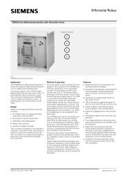
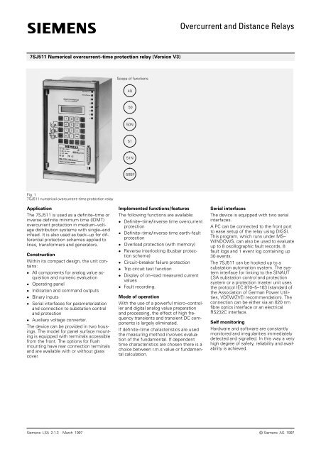
7SJ511 Numerical overcurrent–time protection relay (Version V3)<br />
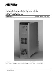
Fig. 1<br />
7SJ511 numerical overcurrent–time protection relay<br />
Application<br />
The 7SJ511 is used as a definite–time or<br />
inverse definite minimum time (IDMT)<br />
overcurrent protection in medium–voltage<br />
distribution systems with single–end<br />
infeed. It is also used as back–up for differential<br />
protection schemes applied to<br />
lines, transformers <strong>and</strong> generators.<br />
Construction<br />
Within its compact design, the unit contains:<br />
� All components for analog value acquisition<br />
<strong>and</strong> numeric evaluation<br />
� Operating panel<br />
� Indication <strong>and</strong> comm<strong>and</strong> outputs<br />
� Binary inputs<br />
� Serial interfaces for parameterization<br />
<strong>and</strong> connection to substation control<br />
<strong>and</strong> protection<br />
� Auxiliary voltage converter.<br />
The device can be provided in two housings.<br />
The model for panel surface mounting<br />
is equipped with terminals accessible<br />
from the front. The options for flush<br />
mounting have rear connection terminals<br />
<strong>and</strong> are available with or without glass<br />
cover.<br />
Scope of functions<br />
49<br />
50<br />
50N<br />
51<br />
51N<br />
50BF<br />
Implemented functions/features<br />
The following functions are available:<br />
� Definite–time/inverse time overcurrent<br />
protection<br />
� Definite–time/inverse time earth–fault<br />
protection<br />
� Overload protection (with memory)<br />
� Reverse interlocking (busbar protection<br />
scheme)<br />
� Circuit–breaker failure protection<br />
� Trip circuit test function<br />
� Display of on–load measured current<br />
values<br />
� Fault recording.<br />
Mode of operation<br />
With the use of a powerful micro–controller<br />
<strong>and</strong> digital analog value preparation<br />
<strong>and</strong> processing, the effect of high frequency<br />
transients <strong>and</strong> transient DC components<br />
is largely eliminated.<br />
If definite–time characteristics are used<br />
the measuring method involves evaluation<br />
of the fundamental. If dependent<br />
time characteristics are chosen there is a<br />
choice between r.m.s value or fundamental<br />
calculation.<br />
<strong>Overcurrent</strong> <strong>and</strong> <strong>Distance</strong> <strong>Relays</strong><br />
Serial interfaces<br />
The device is equipped with two serial<br />
interfaces.<br />
A PC can be connected to the front port<br />
to ease setup of the relay using DIGSI.<br />
This program, which runs under MS–<br />
WINDOWS, can also be used to evaluate<br />
up to 8 oscillographic fault records, 8<br />
fault logs <strong>and</strong> 1 event log containing up<br />
30 events.<br />
The 7SJ511 can be hooked up to a<br />
substation automation system. The system<br />
interface for linking to the SINAUT<br />
LSA substation control <strong>and</strong> protection<br />
system or a protection master unit uses<br />
the protocol IEC 870–5–103 (st<strong>and</strong>ard of<br />
the Association of German Power Utilities,<br />
VDEW/ZVEI recommendation). The<br />
connection can be either via an 820 nm<br />
fibre optics interface or an electrical<br />
RS232C interface.<br />
Self monitoring<br />
Hardware <strong>and</strong> software are constantly<br />
monitored <strong>and</strong> irregularities immediately<br />
detected <strong>and</strong> signalled. In this way a very<br />
high degree of safety, reliability <strong>and</strong> availability<br />
is achieved.<br />
Siemens LSA 2.1.3 . March 1997 Siemens AG 1997 1<br />
�
<strong>Overcurrent</strong> <strong>and</strong> <strong>Distance</strong> <strong>Relays</strong><br />
2<br />
7SJ511 Numerical overcurrent–time protection relay (Version V3)<br />
Convenient setting<br />
The menu driven HMI or connected OC is<br />
used for setting parameters. The parameters<br />
are stored in a non–volatile memory<br />
so that the setting is retained even if the<br />
supply voltage is cut off.<br />
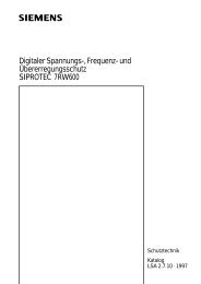
Oscillographic fault recording of up to<br />
8 records (5 seconds maximum)<br />
The ”Fault recording” function is used to<br />
record the phase currents in the event of<br />
a power system fault. Either pickup, tripping<br />
or binary input can be selected to<br />
trigger waveform capture. The maximum<br />
length of a record can be programmed.<br />
The recorded traces of the phase <strong>and</strong><br />
ground currents <strong>and</strong> pickup <strong>and</strong> drop–off<br />
of internal events can be transmitted to a<br />
PC for convenient analysis using DIGRA.<br />
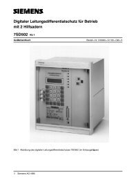
Fig. 2<br />
Settings window using DIGSI<br />
Fig. 3<br />
Analog <strong>and</strong> binary traces<br />
Siemens LSA 2.1.3 . March 1997
7SJ511 Numerical overcurrent–time protection relay (Version V3)<br />
<strong>Overcurrent</strong>–time protection<br />
IEC curves<br />
The function is based on phase–selective<br />
measurement of the three phase currents<br />
<strong>and</strong> the earth current. Either definite–time<br />
or inverse–time maximum current<br />
time protection can be used. In<br />
addition to the overcurrent stage there is<br />
a high current state both for the phases<br />
(�>, �>>) <strong>and</strong> for the earth (�E>, � E>>).<br />
The high current stage always has definite–time<br />
characteristics:<br />
If the 11th place of the order number is 0<br />
(country–specific presettings: German/<br />
English), the following tripping characteristics<br />
can be selected (to BS 142, or<br />
IEC 255–4):<br />
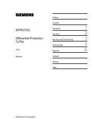
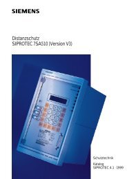
� normal inverse (Fig. 4)<br />
t � tp �<br />
0.14<br />
(��� p ) 0.02 –1<br />
� very inverse (Fig. 5)<br />
t � tp �<br />
13.5<br />
���� p )–1<br />
� extremly inverse (Fig. 6)<br />
t � tp �<br />
80<br />
(��� p ) 2 –1<br />
t tripping time<br />
tp time multiplier 0 – 10 s<br />
� fault current<br />
�p current setting 0.1 – 4 �N t [s]<br />
100<br />
70<br />
50<br />
20<br />
10<br />
7<br />
5<br />
2<br />
1<br />
0.7<br />
0.5<br />
0.2<br />
0.1<br />
0.07<br />
0.05<br />
0.02<br />
0.01<br />
1 2 3 5 7 10 20<br />
Fig. 4<br />
Tripping time characteristics, normal inverse<br />
(IEC 255–4)<br />
t [s]<br />
100<br />
70<br />
50<br />
20<br />
10<br />
7<br />
5<br />
2<br />
1<br />
0.7<br />
0.5<br />
0.2<br />
0.1<br />
0.07<br />
0.05<br />
0.02<br />
<strong>Overcurrent</strong> <strong>and</strong> <strong>Distance</strong> <strong>Relays</strong><br />
Siemens LSA 2.1.3 . March 1997 3<br />
�/�p<br />
0.01<br />
1 2 3 5 7 10 20<br />
�/�p<br />
Fig. 5<br />
Tripping time characteristics, very inverse<br />
(IEC 255–4)<br />
tp = 3.2<br />
tp = 1.6<br />
tp = 1<br />
tp = 0.5<br />
tp = 0.2<br />
tp = 0.1<br />
tp = 0.05<br />
tp = 3.2<br />
tp = 1.6<br />
tp = 1<br />
tp = 0.5<br />
tp = 0.2<br />
tp = 0.1<br />
tp = 0.05<br />
t [s]<br />
100<br />
70<br />
50<br />
20<br />
10<br />
7<br />
5<br />
2<br />
1<br />
0.7<br />
0.5<br />
0.2<br />
0.1<br />
0.07<br />
0.05<br />
0.02<br />
0.01 1 2 3 5 7 10 20<br />
�/�p<br />
tp = 3.2<br />
tp = 1.6<br />
tp = 1<br />
tp = 0.5<br />
tp = 0.2<br />
tp = 0.1<br />
tp = 0.05<br />
Fig. 6<br />
Tripping time characteristics, extremely inverse<br />
(IEC 255–4)
<strong>Overcurrent</strong> <strong>and</strong> <strong>Distance</strong> <strong>Relays</strong><br />
4<br />
7SJ511 Numerical overcurrent–time protection relay (Version V3)<br />
US Curves<br />
The following inverse–time characteristics<br />
have been adapted to the requirements<br />
of the US market.<br />
The US–version has a ”1” in the 11th<br />
place of the order number.<br />
t � � A<br />
(��� p ) N –1<br />
� B� � D<br />
t tripping time<br />
�p current setting<br />
A, B, N parameters<br />
� �–Squared–T Curve (Fig. 7)<br />
t �<br />
50.7 D � 10.14<br />
(��� p ) 2<br />
t tripping time<br />
�p current setting<br />
D time dial setting<br />
100<br />
70<br />
t [s]<br />
50<br />
20<br />
10<br />
7<br />
5<br />
2<br />
1<br />
0.7<br />
0.5<br />
0.2<br />
0.1<br />
0.07<br />
0.05<br />
0.02<br />
0.01 1 2 3 5 7 10 20<br />
�/�p<br />
D = 10<br />
D = 7<br />
D = 5<br />
D = 3.2<br />
D = 1.6<br />
D = 1<br />
D = 0.5<br />
D = 0.2<br />
D = 0.1<br />
D = 0.05<br />
Fig. 7<br />
Tripping time characteristic, �–squared–T curve<br />
Curve type A B N<br />
Inverse 8.9341 0.17966 2.0938<br />
Short inverse 0.2663 0.03393 1.2969<br />
Long inverse 5.6143 2.18592 1.0000<br />
Moderately inverse 0.054196 0.09328 0.0200<br />
Very inverse 19.138 0.48258 2.0000<br />
Extremely inverse 28.2785 0.12173 2.0000<br />
Definite inverse 0.4797 0.21359 1.5625<br />
100<br />
70<br />
t [s]<br />
50<br />
20<br />
10<br />
7<br />
5<br />
2<br />
1<br />
0.7<br />
0.5<br />
0.2<br />
0.1<br />
0.07<br />
0.05<br />
0.02<br />
0.01 D = 0.05<br />
1 2 3 5 7 10 20<br />
�/�p<br />
Fig. 8<br />
Tripping time characteristic, inverse<br />
D = 10<br />
D = 7<br />
D = 5<br />
D = 3.2<br />
D = 1.6<br />
D = 1<br />
D = 0.5<br />
D = 0.2<br />
D = 0.1<br />
100<br />
70<br />
t [s]<br />
50<br />
20<br />
10<br />
7<br />
5<br />
2<br />
1<br />
0.7<br />
0.5<br />
0.2<br />
0.1<br />
0.07<br />
0.05<br />
0.02<br />
0.01 1 2 3 5 7 10 20<br />
�/�p<br />
D = 10<br />
D = 7<br />
D = 5<br />
D = 3.2<br />
D = 1.6<br />
D = 1<br />
D = 0.5<br />
D = 0.2<br />
D = 0.1<br />
D = 0.05<br />
Fig. 9<br />
Tripping time characteristic, moderately inverse<br />
Siemens LSA 2.1.3 . March 1997
7SJ511 Numerical overcurrent–time protection relay (Version V3)<br />
100<br />
70<br />
t [s]<br />
50<br />
20<br />
10<br />
7<br />
5<br />
2<br />
1<br />
0.7<br />
0.5<br />
0.2<br />
0.1<br />
0.07<br />
0.05<br />
0.02<br />
D = 0.2<br />
D = 0.1<br />
D = 0.05<br />
0.01<br />
1 2 3 5 7 10 20<br />
�/�p<br />
Fig. 10<br />
Tripping time characteristic, short inverse<br />
100<br />
70<br />
t [s]<br />
50<br />
20<br />
10<br />
7<br />
5<br />
2<br />
1<br />
0.7<br />
0.5<br />
0.2<br />
0.1<br />
0.07<br />
0.05<br />
0.02<br />
0.01 1 2 3 5 7 10 20<br />
�/�p<br />
Fig. 11<br />
Tripping time characteristic, very inverse<br />
D = 10<br />
D = 7<br />
D = 5<br />
D = 3.2<br />
D = 1.6<br />
D = 1<br />
D = 0.5<br />
D = 10<br />
D = 7<br />
D = 5<br />
D = 3.2<br />
D = 1.6<br />
D = 1<br />
D = 0.5<br />
D = 0.2<br />
D = 0.1<br />
D = 0.05<br />
100<br />
70<br />
t [s]<br />
50<br />
20<br />
10<br />
7<br />
5<br />
2<br />
1<br />
0.7<br />
0.5<br />
0.2<br />
0.1<br />
0.07<br />
0.05<br />
0.02<br />
0.01 1 2 3 5 7 10 20<br />
Fig. 12<br />
Tripping time characteristic, long inverse<br />
100<br />
70<br />
t [s]<br />
50<br />
20<br />
10<br />
7<br />
5<br />
2<br />
1<br />
0.7<br />
0.5<br />
0.2<br />
0.1<br />
0.07<br />
0.05<br />
<strong>Overcurrent</strong> <strong>and</strong> <strong>Distance</strong> <strong>Relays</strong><br />
Siemens LSA 2.1.3 . March 1997 5<br />
�/�p<br />
I/Ip<br />
D = 10<br />
D = 7<br />
D = 5<br />
D = 3.2<br />
D = 1.6<br />
D = 1<br />
D = 0.5<br />
D = 0.2<br />
D = 0.1<br />
D = 0.05<br />
D = 10<br />
D = 7<br />
D = 5<br />
D = 3.2<br />
D = 1.6<br />
D = 1<br />
D = 0.5<br />
D = 0.2<br />
0.02<br />
0.01<br />
1 2 3<br />
D = 0.05<br />
5 7 10<br />
D = 0.1<br />
20<br />
Fig. 13<br />
Tripping time characteristic, extremely inverse<br />
100<br />
70<br />
t [s]<br />
50<br />
20<br />
10<br />
7<br />
5<br />
2<br />
1<br />
0.7<br />
0.5<br />
0.2<br />
0.1<br />
0.07<br />
0.05<br />
0.02<br />
0.01 D = 0.05<br />
1 2 3 5 7 10 20<br />
�/�p<br />
D = 10<br />
D = 7<br />
D = 5<br />
D = 3.2<br />
D = 1.6<br />
D = 1<br />
D = 0.5<br />
D = 0.2<br />
D = 0.1<br />
Fig. 14<br />
Tripping time characteristic, definite inverse
<strong>Overcurrent</strong> <strong>and</strong> <strong>Distance</strong> <strong>Relays</strong><br />
6<br />
7SJ511 Numerical overcurrent–time protection relay (Version V3)<br />
Earth–fault protection<br />
For protection against high–resistance<br />
earth–faults in earthed networks, it is<br />
possible to monitor the earth current via<br />
an independent fourth input current transformer.<br />
As for the phase current protection,<br />
a choice may be made between the<br />
definite–time <strong>and</strong> the IDMT overcurrent<br />
characteristics, both having definite–time<br />
high–set overcurrent characteristic.<br />
Intermittend earth–fault protection<br />
with firmware V3.1<br />
Intermittend (re–striking) faults occur due<br />
to insulation weaknesses in cables or as<br />
a result of water penetrating cable joints.<br />
Such faults either simply cease at some<br />
stage or develop into lasting short–circuits.<br />
During intermittent activity, however,<br />
starpoint resistors in networks that<br />
are impedance–earthed may undergo<br />
thermal overloading. The normal earth–<br />
fault protection cannot reliably detect <strong>and</strong><br />
interrupt the current pulses, some of<br />
which can be very brief.<br />
The selectivity required with intermittent<br />
earth faults is achieved by summating<br />
the durations of the individual pulses <strong>and</strong><br />
by triggering when a (settable) summed<br />
time is reached. The response threshold<br />
��E> evaluates the rms value, referred to<br />
one systems period.<br />
Reverse interlocking<br />
Blocking of any stage (e.g. �>>) is possible<br />
via a binary input. Thus, the numerical<br />
overcurrent protection 7SJ511 can be<br />
used as a fast busbar protection in wye<br />
connected networks or in open ring networks<br />
(ring open at one location), using<br />
the reverse interlock principle. This can<br />
be used in medium–voltage systems, in<br />
power station auxiliary supplement networks,<br />
etc., in which cases a transformer<br />
feeds from a higher–voltage system onto<br />
a busbar with several outgoing feeders.<br />
Thermal overload protection<br />
For the protection of cables or machines,<br />
an overload protection with a pre–warning<br />
stage for temperature <strong>and</strong> current is<br />
implemented. The temperature of the<br />
equipment to be protected is determined<br />
using a thermal homogeneous body<br />
model that contains energy input to the<br />
equipment <strong>and</strong> energy output to the environment.<br />
In this way currents that<br />
change over time <strong>and</strong> pre–loading can be<br />
taken into account (overload protection<br />
with memory).<br />
Using a parameter, it is possible to select<br />
whether the maximum of the phase–related<br />
conductor temperature or the mean<br />
value of these is to be taken as the determining<br />
value. It is also possible to calculate<br />
the temperature from the maximum<br />
value of the conductor current.<br />
Circuit–breaker failure protection<br />
After the issue of a trip comm<strong>and</strong> by the<br />
relay or upon the excitation of a digital<br />
input by an external protection, the<br />
breaker failure current check function is<br />
initiated.<br />
If current is still detected after the set<br />
time (e.g. in the case of a breaker failure),<br />
an alarm relay or a comm<strong>and</strong> relay<br />
(for breaker failure tripping) is energized.<br />
Inrush stabilization<br />
When switching on a transformer the<br />
7SJ511 can distinguish between inrush<br />
<strong>and</strong> real short–circuits. Inrush is particularly<br />
noticeable by its relatively high second<br />
harmonic content. In the case of a<br />
short–circuit, the second harmonic content<br />
is almost non–existent. The harmonic<br />
stabilization operates independently<br />
for each of the three phases.<br />
When using inrush stabilization on one<br />
phase, it is also possible to block the remaining<br />
phases (cross block). When using<br />
inrush detection the pick–up of the<br />
high–set element stays active, <strong>and</strong> the<br />
normal overcurrent element is blocked.<br />
Fault recording<br />
The digitized analog values of phase currents<br />
<strong>and</strong> earth current are stored in the<br />
event of a fault. The analog values recorded<br />
can be transferred to a PC where<br />
they can be displayed, analyzed <strong>and</strong> archived<br />
using DIGSI. As an option they<br />
can be read out by the SINAUT LSA<br />
substation control <strong>and</strong> protection system.<br />
The serial interface conforms to VDEW/<br />
ZVEI. Up to eight fault recordings can be<br />
stored. The fault recording buffer is a circulating<br />
buffer with a maximum length so<br />
that when it is full every new network<br />
fault overwrites the oldest recorded fault.<br />
A total of 5 seconds are available for the<br />
recording duration.<br />
Indications<br />
The 7SJ511 supplies detailed data for<br />
analyzing faults <strong>and</strong> checking states during<br />
operation. All the following indications<br />
are protected against supply voltage failure,<br />
in case there is a battery–backed<br />
clock.<br />
� Time<br />
Time can be synchronized via a binary<br />
input or the serial interface. The date<br />
<strong>and</strong> time are assigned to all indications.<br />
� Fault indications<br />
The indications of the faults in the device<br />
are available with a resolution of<br />
1 ms.<br />
� Operational indications<br />
All indications that do not immediately<br />
refer to a fault (e.g. operating or<br />
switching actions) are stored in the operational<br />
indication buffer (resolution<br />
1 ms).<br />
Circuit–breaker trip circuit test function<br />
The integrity of the circuit–breaker trip<br />
circuit can be tested via an operator initiated<br />
trip comm<strong>and</strong>. This test can be initiated<br />
via the front panel keyboard or operator<br />
serial interface, but only after input<br />
of a code word.<br />
Marshalling of comm<strong>and</strong> <strong>and</strong> alarm/<br />
event relays, LEDs <strong>and</strong> binary inputs<br />
All input/output relays <strong>and</strong> indicating<br />
LEDs may be functionally allocated according<br />
to the user‘s requirements.<br />
Several indications can be assigned to<br />
one output relay, LED or binary input simultaneously.<br />
In this case they are<br />
ORed.<br />
Measuring, monitoring <strong>and</strong> testing<br />
functions<br />
The following functions are available for<br />
commissioning, operational measurement<br />
<strong>and</strong> monitoring:<br />
� Measuring of currents: � L1, � L2, � L3, � E<br />
� Monitoring of current sum <strong>and</strong> current<br />
symmetry.<br />
� Tripping test with circuit–breaker.<br />
Siemens LSA 2.1.3 . March 1997
7SJ511 Numerical overcurrent–time protection relay (Version V3)<br />
Technical data<br />
Input circuits Rated current �N<br />
Rated frequency fN<br />
Thermal overload capability in current path<br />
continuous<br />
1 s<br />
Dynamic overload capability (half cycle)<br />
Burden<br />
of current inputs at �N = 1 A<br />
at �N = 5 A<br />
Voltage supply<br />
via integrated DC/DC converter<br />
Rated auxiliary voltage Vaux/permissible ranges<br />
Max. ripple at rated voltage<br />
Power consumption, quiescent<br />
energized<br />
Max. bridging time during loss of voltage supply<br />
Binary inputs Number<br />
Voltage range<br />
Current consumption independent of operating voltage<br />
Alarm/event contacts Number of relays, each having 1 C/O contact<br />
Switching capacity make/break<br />
Switching voltage<br />
Permissible current, continuous<br />
Comm<strong>and</strong> contacts Number of relays, each having 2 NO contacts<br />
Switching capacity make<br />
break<br />
Switching voltage<br />
Permissible current, continuous<br />
0.5 s<br />
LED displays Ready indication green<br />
Blocked indication red<br />
Marshallable LEDs red<br />
Serial interfaces Operator interface<br />
Connection<br />
Potential free system interface<br />
for data transmission to control center<br />
St<strong>and</strong>ard<br />
Baud rate<br />
Transmission reliability<br />
Connection, direct on flush–mounted housing<br />
on surface–mounted housing<br />
distance<br />
test voltage<br />
Connection fibre optic cable<br />
optical wavelength<br />
permissible attenuation<br />
distance<br />
no character<br />
Construction of unit Case, dimensions<br />
Weight flush mounting/cubicle mounting<br />
surface mounting<br />
Degree of protection according to EN 60 529<br />
<strong>Overcurrent</strong> <strong>and</strong> <strong>Distance</strong> <strong>Relays</strong><br />
1 or 5 A<br />
50 or 60 Hz<br />
4 x �N<br />
100 x �N<br />
250 x �N<br />
approx 0.1 VA<br />
approx. 0.2 VA<br />
24, 48 V DC or / 19 to 56 V DC<br />
60, 110, 125 V DC or / 48 to 144 V DC<br />
220, 250 V DC or / 176 to 288 V DC<br />
�12 %<br />
approx. 5 W<br />
approx. 10 W<br />
�50 ms at Vaux �110 V DC<br />
2 (marshallable)<br />
24 to 250 V DC<br />
approx. 2.5 mA<br />
5 (marshallable)<br />
20 W/VA<br />
250 V AC/DC<br />
1 A<br />
2 (marshallable)<br />
1 000 W/VA<br />
30 W/VA<br />
250 V AC/DC<br />
5 A<br />
30 A<br />
Siemens LSA 2.1.3 . March 1997 7<br />
1<br />
1<br />
6<br />
not isolated<br />
on front panel, 25–pole subminiature plug<br />
ISO 2110 for the connection of a PC<br />
isolated<br />
similar to V.24/V.28 (RS232C)<br />
according to EIA, DIN 19 244<br />
9 600 Bd setting as supplied;<br />
min. 4 800 Bd, max. 19 200 Bd<br />
hamming distance d = 4<br />
at rear, 4–pole module connector<br />
at two–tier terminal at the top <strong>and</strong> bottom<br />
of the housing<br />
cable with 2 core pairs, with individual <strong>and</strong><br />
common screening:<br />
e.g. LIYCY–CY/2 x 2 x o.25 mm 2<br />
max. 1 km<br />
2 kV with rated frequency for 1 min<br />
integrated FSMA connectors for FO<br />
connection<br />
on flush–mounted housing: at rear<br />
on surface–mounted housing: at the<br />
bottom of housing<br />
820 nm<br />
max. 8 dB with glassfibre 62.5/125 �m<br />
max. 2 km<br />
switchable; setting as supplied ”light off”<br />
7XP20, see dimension drawings<br />
approx. 9.5 kg<br />
approx. 11 kg<br />
IP51
<strong>Overcurrent</strong> <strong>and</strong> <strong>Distance</strong> <strong>Relays</strong><br />
Technical data (continued)<br />
CE–conformity, st<strong>and</strong>ards This product is in conformity with the directives of the Council of<br />
the European Communities on the approximation of the laws of<br />
the Member States relating to the electromagnetic compatibility<br />
(EMC Council Directive 89/336/EEC) <strong>and</strong> concerning electrical<br />
equipment for use within specified voltage limits (low voltage<br />
directive 73/23/EEC). The product conforms with the international<br />
st<strong>and</strong>ard IEC 255 <strong>and</strong> the national st<strong>and</strong>ard DIN 57 435 part 303<br />
(corresponding to VDE 0435 part 303).<br />
The relay is designed for use in an industrial environment, for<br />
installation in st<strong>and</strong>ard relay rooms <strong>and</strong> compartments so that<br />
with proper installation electro–magnetic compatibility (EMC) is<br />
ensured.<br />
8<br />
7SJ511 Numerical overcurrent–time protection relay (Version V3)<br />
Insulation tests<br />
IEC 255–5, DIN 57 435 part 303<br />
EMC–tests; immunity (type test)<br />
St<strong>and</strong>ards: IEC 255–6, IEC255–22<br />
(international product st<strong>and</strong>ard)<br />
EN 50082–2 (generic st<strong>and</strong>ard)<br />
VDE 0435 part 303 (German<br />
product st<strong>and</strong>ard)<br />
EMC–tests; emission (type test)<br />
St<strong>and</strong>ard: EN 50081–* (European generic<br />
st<strong>and</strong>ard)<br />
High voltage test (routine test), except d.c. voltage supply input<br />
High voltage test (routine test), only d.c. voltage supply input<br />
Impulse voltage test (type test), all circuits, class III<br />
High frequency test with 1 MHz interference<br />
IEC 255–22–1, class III <strong>and</strong> VDE 0435 part 303, class III<br />
Electrostatic discharge<br />
IEC 255–22–2, class III <strong>and</strong> IEC 1000–4–2, class III<br />
Radio–frequency electromagnetic field, non–modulated<br />
report IEC 255–22–3, class III<br />
Radio–frequency electromagnetic field, amplitude modulated<br />
IEC 1000–4–3, class III<br />
Radio–frequency electromagnetic field, puls modulated<br />
ENV 50204, class III<br />
Fast transients<br />
IEC 255–22–4 class III, IEC 1000–4–4 class III<br />
Conducted disturbances induced by radio–frequency fields,<br />
amplitude modulated<br />
IEC 1000–4–6, class III<br />
Power frequency magnetic field<br />
IEC 1000–4–8, class IV<br />
IEC 255–6<br />
Conducted interference voltage, auxiliary voltage<br />
CISPR 22, EN 55022 <strong>and</strong> VDE 0878 part 22<br />
Interference field strength<br />
CISPR 11, EN 55011 <strong>and</strong> VDE 0878 part 11<br />
Climatic stress tests permissible ambient temperature during service<br />
during storage<br />
during transport<br />
permissible humidity<br />
Mechanical stress tests<br />
IEC 255–21–1, IEC 68–2<br />
Overload protection Factor k<br />
Time constant �<br />
Warning temperature �Warn<br />
Current warning stage �Warn<br />
Breaker–failure protection Triggering threshold �><br />
Delay time tSVS<br />
Fault recording Measured values<br />
Start signal<br />
permissible mechanical stress during service<br />
Recording duration<br />
Holding time<br />
Operational analog values Currents<br />
Measuring ranges<br />
during transport<br />
Conformity is proved by tests performed<br />
by Siemens AG in line with article 10 of the<br />
Council Directives in accordance with the<br />
generic st<strong>and</strong>ards EN 50081 <strong>and</strong> EN 50082<br />
for the EMC directive 89/336/EEC <strong>and</strong><br />
st<strong>and</strong>ard 60255–6 for the low voltage directive.<br />
2 kV (rms), 50 Hz<br />
2.8 kV DC<br />
5 kV (peak), 1.2/50 �s, 0.5 J,<br />
3 positive <strong>and</strong> 3 negative shots at intervals<br />
of 5 s<br />
2.5 kV (peak), 1 MHz, � = 15 �s,<br />
400 shots/s, duration 2 s<br />
4 / 6 kV contact discharge, 8 kV air discharge,<br />
both polarities, 150 pF, Rl = 330 �<br />
10 V/m, 27 to 500 MHz<br />
10 V/m, 80 to 1 000 MHz, AM 80 %, 1 kHz,<br />
10 V/m, 900 MHz, repetition frequency<br />
200 Hz, duty cycle 50 %<br />
2 kV, 5/50 ns, 5 kHz, burst length = 15 ms,<br />
repetition rate 300 ms, both polarities,<br />
Rl = 50 �� duration 1 min<br />
10 V, 150 kHz to 80 MHz, AM 80 %, 1 kHz,<br />
30 A /m, continuous, 300 A /m for 3 s, 50 Hz<br />
0.5 mT; 50 Hz<br />
150 kHz to 30 MHz<br />
class B<br />
30 to 1 000 MHz<br />
class A<br />
–5 to +55 °C<br />
–25 to +55 °C<br />
–25 to +70 °C<br />
mean value per year �75 % relative humidity,<br />
on 30 days per year up to 95 % relative<br />
humidity, condensation not permissible<br />
10 to 60 Hz, 0,035 mm amplitude<br />
60 to 500 Hz, 0,5 g acceleration<br />
5 to 8 Hz, 7,5 mm amplitude<br />
8 to 500 Hz, 2 g acceleration<br />
0.1 to 4<br />
1 to 999.9 min<br />
50 to 100%<br />
0.1 to 4 x �/�N<br />
0.1 to 4 x �/�N<br />
0.06 to 60 s <strong>and</strong> infinity<br />
iL1, iL2, iL3, iE<br />
Trip, energization, binary, input, LSA,<br />
integrated operating panel<br />
Max. 5 s<br />
Until fault–recording buffer full. New fault<br />
entries overwrite the oldest recorded<br />
faults.<br />
�L1, �L2, �L3, �E<br />
0 to 240 % x �N<br />
Siemens LSA 2.1.3 . March 1997
7SJ511 Numerical overcurrent–time protection relay (Version V3)<br />
Technical data (continued)<br />
Definite–time overcurrent protection <strong>Overcurrent</strong> phase �><br />
earth �E><br />
High set current phase �<br />
earth �E<br />
Delay times<br />
Tolerances<br />
Current pick–up value<br />
Time<br />
Reset time<br />
Inverse–time overcurrent protection <strong>Overcurrent</strong> phase �p<br />
earth �Ep<br />
High set current phase �� (DMT)<br />
earth �E� (DMT)<br />
Time multiplier tp<br />
Pick–up value<br />
Characteristics according to IEC255–4, paragraph 3.5.2 or BS142<br />
(if 11th place of order number = 0)<br />
US curves<br />
(if 11th place of order number = 1)<br />
Linear current range<br />
Tolerances<br />
Pick–up value<br />
Time<br />
Shortest operating time201<br />
<strong>Overcurrent</strong> <strong>and</strong> <strong>Distance</strong> <strong>Relays</strong><br />
�/�N = 0.1 to 25<br />
�/�N = 0.1 to 25<br />
�/�N = 0.1 to 25<br />
�/�N = 0.1 to 25<br />
0 to 60 s or infinity<br />
�5 % of set value<br />
�1 % or �10 ms<br />
approx. 30 ms<br />
�p/�N = 0.1 to 4<br />
�p/�N = 0.1 to 4<br />
�/�N = 0.1 to 25<br />
�/�N = 0.1 to 25<br />
0,05 to 3,2 s<br />
1.1 x �p<br />
normal inverse, very inverse, extremely<br />
inverse<br />
�p: 0.1 to 4, D: 0 to 10s<br />
Siemens LSA 2.1.3 . March 1997 9<br />
25 x �N<br />
�5 %<br />
�5 % for 2 �(�/�p>) �20 <strong>and</strong> tp = 1<br />
<strong>Overcurrent</strong> <strong>and</strong> <strong>Distance</strong> <strong>Relays</strong><br />
10<br />
7SJ511 Numerical overcurrent–time protection relay (Version V3)<br />
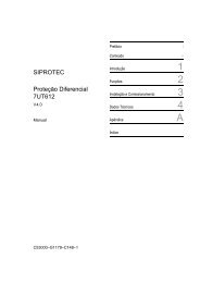
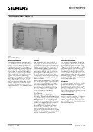
L1<br />
L2<br />
L3<br />
L1 L2 L3<br />
�E<br />
�L1<br />
�L2<br />
�L3<br />
Power supply<br />
Fig. 15<br />
Connection diagram, 7SJ511 numercial overcurrent–time protection relay<br />
�L1<br />
�L2<br />
�L3<br />
�E<br />
RxD<br />
MR<br />
1<br />
5<br />
2<br />
6<br />
3<br />
7<br />
4<br />
8<br />
21<br />
22<br />
23<br />
24<br />
10<br />
11<br />
31<br />
32<br />
Version for panel surface mounting<br />
4C2<br />
4C1<br />
3C2<br />
3C1<br />
2C2<br />
2C1<br />
1C2<br />
1C1<br />
1D1<br />
1D2<br />
1D3<br />
1D4<br />
4D1<br />
4D2<br />
6C1<br />
6C2<br />
Version for panel flush mounting/cubicle mounting<br />
L+<br />
L–<br />
Binary<br />
input 1<br />
Binary<br />
input 2<br />
Signal relay 1<br />
Signal relay 2<br />
Signal relay 3<br />
Signal relay 4<br />
Relay blocked<br />
Comm<strong>and</strong><br />
relay 1<br />
Comm<strong>and</strong><br />
relay 2<br />
7SJ511<br />
V.24 serial interface, 2 kV isolation<br />
connection to central control unit<br />
Fibre optic interface<br />
connection to central control unit<br />
8D3 39<br />
8D2 38<br />
8D1 37<br />
7D3 42<br />
7D2 41<br />
7D1 40<br />
6D3 45<br />
6D2 44<br />
6D1 43<br />
5D3 57<br />
5D2 56<br />
5D1 55<br />
7D4 60<br />
8D4 59<br />
6D4 58<br />
8C1<br />
8C3<br />
8C4<br />
8C2<br />
7C1<br />
7C3<br />
7C4<br />
7C2<br />
12<br />
27<br />
28<br />
13<br />
14<br />
29<br />
30<br />
15<br />
6C3 46<br />
6C4 47<br />
TxD<br />
MT<br />
V.24 (RS232C)<br />
or fibre optic interface<br />
(optional)<br />
Siemens LSA 2.1.3 . March 1997
Dimension drawings in mm<br />
Front view Side view<br />
Fig. 16<br />
7SJ511 with housing 7XP2030–2 (for panel flush mounting or cubicle mounting)<br />
1<br />
16<br />
145<br />
150<br />
159<br />
. . . . .<br />
31 45<br />
46 . . . . . 60<br />
. . . . .<br />
. . . . .<br />
144<br />
15<br />
30<br />
280<br />
Fibre optic<br />
connection<br />
344<br />
10<br />
30 172<br />
29.5<br />
244<br />
231.5<br />
Front view Side view<br />
Fig. 17<br />
7SJ511 with housing 7XP2030–1 (for panel surface mounting with two–tier terminals)<br />
27<br />
39<br />
71<br />
<strong>Overcurrent</strong> <strong>and</strong> <strong>Distance</strong> <strong>Relays</strong><br />
Panel cutout<br />
Siemens LSA 2.1.3 . March 1997 11<br />
1.5<br />
260<br />
266<br />
Cutout 20 x 60<br />
(without paint)<br />
40<br />
Z<br />
1.5<br />
7.3<br />
13.2<br />
245<br />
29.5<br />
266<br />
131.5<br />
105<br />
Diam. 5 or M4<br />
Diam. 6<br />
146<br />
5.4<br />
255.8<br />
Fibre optic interface<br />
Detail Z:
<strong>Overcurrent</strong> <strong>and</strong> <strong>Distance</strong> <strong>Relays</strong><br />
Conditions of Sale <strong>and</strong> Delivery � Export Regulations � Trademarks � Dimensions<br />
Conditions of Sale <strong>and</strong> Delivery<br />
Subject to the<br />
General Conditions of Supply <strong>and</strong> Delivery<br />
for Products <strong>and</strong> Services of the<br />
Electrical <strong>and</strong> Electronic Industry<br />
<strong>and</strong> to any other conditions agreed upon<br />
with the recipients of catalogs.<br />
Export Regulations<br />
In accordance with present provisions of<br />
the German Export List <strong>and</strong> the US Commercial<br />
Control List, export licences are<br />
not required for the products listed in this<br />
catalog.<br />
Trademarks<br />
All product designations used are trademarks<br />
or product names of Siemens AG<br />
or of other suppliers.<br />
Siemens online!<br />
The Power Transmission <strong>and</strong> Distribution<br />
Group can also be found in the Internet:<br />
http://www.ev.siemens.de<br />
Responsible for<br />
Technical contents: Hans Heining–Triebs,<br />
Siemens AG, EV S V 13, Nürnberg<br />
General editing: Rol<strong>and</strong> Reichel/Claudia Kühn–Sutiono,<br />
Siemens AG, EV S SUP22, Nürnberg/EV BK T, Erlangen<br />
Bereich<br />
Energieübertragung und -verteilung<br />
Geschäftsgebiet Sekundärsysteme<br />
P. O. Box 48 06<br />
D-90026 Nürnberg<br />
12 Siemens Aktiengesellschaft<br />
�<br />
The technical data, dimensions <strong>and</strong><br />
weights are subject to change unless<br />
otherwise stated on the individual pages<br />
of this catalog.<br />
The illustrations are for reference only.<br />
An export licence may however be required<br />
due to country–specific application of<br />
the products.<br />
Dimensions<br />
All dimensions in this catalog are given in<br />
mm.<br />
We reserve the right to adjust the prices<br />
<strong>and</strong> shall charge the price applying on<br />
the date of delivery.<br />
Relevant are the criteria stated in the delivery<br />
note <strong>and</strong> the invoice.<br />
Subject to change without notice.<br />
A 9.91 a<br />
Power<br />
Transmission<br />
<strong>and</strong> Distribution<br />
Siemens LSA 2.1.3 . Order No.: E50001-K5712–A131-A2–7600 March 1997<br />
Printed in Germany<br />
KG K 0397 6.0 SC 12 En 321525 6106/U497