<strong>Overcurrent</strong> <strong>and</strong> <strong>Distance</strong> <strong>Relays</strong> Technical data (continued) CE–conformity, st<strong>and</strong>ards This product is in conformity with the directives of the Council of the European Communities on the approximation of the laws of the Member States relating to the electromagnetic compatibility (EMC Council Directive 89/336/EEC) <strong>and</strong> concerning electrical equipment for use within specified voltage limits (low voltage directive 73/23/EEC). The product conforms with the international st<strong>and</strong>ard IEC 255 <strong>and</strong> the national st<strong>and</strong>ard DIN 57 435 part 303 (corresponding to VDE 0435 part 303). The relay is designed for use in an industrial environment, for installation in st<strong>and</strong>ard relay rooms <strong>and</strong> compartments so that with proper installation electro–magnetic compatibility (EMC) is ensured. 8 7SJ511 Numerical overcurrent–time protection relay (Version V3) Insulation tests IEC 255–5, DIN 57 435 part 303 EMC–tests; immunity (type test) St<strong>and</strong>ards: IEC 255–6, IEC255–22 (international product st<strong>and</strong>ard) EN 50082–2 (generic st<strong>and</strong>ard) VDE 0435 part 303 (German product st<strong>and</strong>ard) EMC–tests; emission (type test) St<strong>and</strong>ard: EN 50081–* (European generic st<strong>and</strong>ard) High voltage test (routine test), except d.c. voltage supply input High voltage test (routine test), only d.c. voltage supply input Impulse voltage test (type test), all circuits, class III High frequency test with 1 MHz interference IEC 255–22–1, class III <strong>and</strong> VDE 0435 part 303, class III Electrostatic discharge IEC 255–22–2, class III <strong>and</strong> IEC 1000–4–2, class III Radio–frequency electromagnetic field, non–modulated report IEC 255–22–3, class III Radio–frequency electromagnetic field, amplitude modulated IEC 1000–4–3, class III Radio–frequency electromagnetic field, puls modulated ENV 50204, class III Fast transients IEC 255–22–4 class III, IEC 1000–4–4 class III Conducted disturbances induced by radio–frequency fields, amplitude modulated IEC 1000–4–6, class III Power frequency magnetic field IEC 1000–4–8, class IV IEC 255–6 Conducted interference voltage, auxiliary voltage CISPR 22, EN 55022 <strong>and</strong> VDE 0878 part 22 Interference field strength CISPR 11, EN 55011 <strong>and</strong> VDE 0878 part 11 Climatic stress tests permissible ambient temperature during service during storage during transport permissible humidity Mechanical stress tests IEC 255–21–1, IEC 68–2 Overload protection Factor k Time constant � Warning temperature �Warn Current warning stage �Warn Breaker–failure protection Triggering threshold �> Delay time tSVS Fault recording Measured values Start signal permissible mechanical stress during service Recording duration Holding time Operational analog values Currents Measuring ranges during transport Conformity is proved by tests performed by Siemens AG in line with article 10 of the Council Directives in accordance with the generic st<strong>and</strong>ards EN 50081 <strong>and</strong> EN 50082 for the EMC directive 89/336/EEC <strong>and</strong> st<strong>and</strong>ard 60255–6 for the low voltage directive. 2 kV (rms), 50 Hz 2.8 kV DC 5 kV (peak), 1.2/50 �s, 0.5 J, 3 positive <strong>and</strong> 3 negative shots at intervals of 5 s 2.5 kV (peak), 1 MHz, � = 15 �s, 400 shots/s, duration 2 s 4 / 6 kV contact discharge, 8 kV air discharge, both polarities, 150 pF, Rl = 330 � 10 V/m, 27 to 500 MHz 10 V/m, 80 to 1 000 MHz, AM 80 %, 1 kHz, 10 V/m, 900 MHz, repetition frequency 200 Hz, duty cycle 50 % 2 kV, 5/50 ns, 5 kHz, burst length = 15 ms, repetition rate 300 ms, both polarities, Rl = 50 �� duration 1 min 10 V, 150 kHz to 80 MHz, AM 80 %, 1 kHz, 30 A /m, continuous, 300 A /m for 3 s, 50 Hz 0.5 mT; 50 Hz 150 kHz to 30 MHz class B 30 to 1 000 MHz class A –5 to +55 °C –25 to +55 °C –25 to +70 °C mean value per year �75 % relative humidity, on 30 days per year up to 95 % relative humidity, condensation not permissible 10 to 60 Hz, 0,035 mm amplitude 60 to 500 Hz, 0,5 g acceleration 5 to 8 Hz, 7,5 mm amplitude 8 to 500 Hz, 2 g acceleration 0.1 to 4 1 to 999.9 min 50 to 100% 0.1 to 4 x �/�N 0.1 to 4 x �/�N 0.06 to 60 s <strong>and</strong> infinity iL1, iL2, iL3, iE Trip, energization, binary, input, LSA, integrated operating panel Max. 5 s Until fault–recording buffer full. New fault entries overwrite the oldest recorded faults. �L1, �L2, �L3, �E 0 to 240 % x �N Siemens LSA 2.1.3 . March 1997
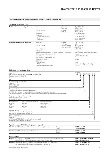
7SJ511 Numerical overcurrent–time protection relay (Version V3) Technical data (continued) Definite–time overcurrent protection <strong>Overcurrent</strong> phase �> earth �E> High set current phase � earth �E Delay times Tolerances Current pick–up value Time Reset time Inverse–time overcurrent protection <strong>Overcurrent</strong> phase �p earth �Ep High set current phase �� (DMT) earth �E� (DMT) Time multiplier tp Pick–up value Characteristics according to IEC255–4, paragraph 3.5.2 or BS142 (if 11th place of order number = 0) US curves (if 11th place of order number = 1) Linear current range Tolerances Pick–up value Time Shortest operating time201 <strong>Overcurrent</strong> <strong>and</strong> <strong>Distance</strong> <strong>Relays</strong> �/�N = 0.1 to 25 �/�N = 0.1 to 25 �/�N = 0.1 to 25 �/�N = 0.1 to 25 0 to 60 s or infinity �5 % of set value �1 % or �10 ms approx. 30 ms �p/�N = 0.1 to 4 �p/�N = 0.1 to 4 �/�N = 0.1 to 25 �/�N = 0.1 to 25 0,05 to 3,2 s 1.1 x �p normal inverse, very inverse, extremely inverse �p: 0.1 to 4, D: 0 to 10s Siemens LSA 2.1.3 . March 1997 9 25 x �N �5 % �5 % for 2 �(�/�p>) �20 <strong>and</strong> tp = 1