TBox-MS Technical Specifications & Cabling
TBox-MS Technical Specifications & Cabling
TBox-MS Technical Specifications & Cabling

Create successful ePaper yourself
Turn your PDF publications into a flip-book with our unique Google optimized e-Paper software.
A<br />
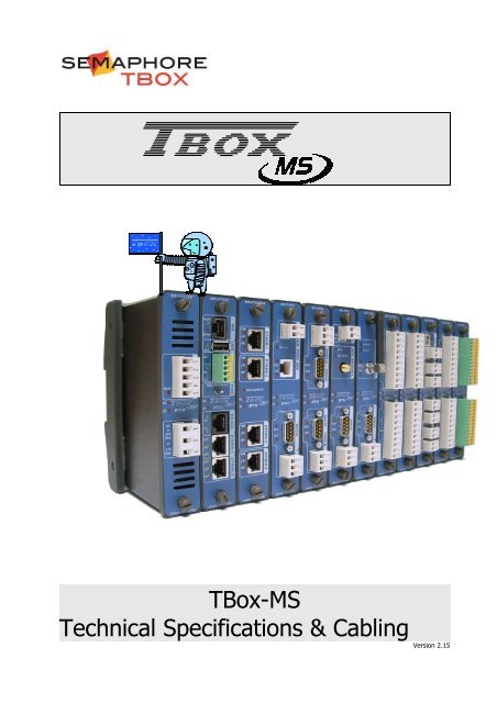
<strong>TBox</strong>-<strong>MS</strong><br />
<strong>Technical</strong> <strong>Specifications</strong> & <strong>Cabling</strong> Version 2.15
Certifications<br />
CE FCC CSA for US<br />
and Canada<br />
C-Tick A-Tick Telepermit<br />
Disclaimer<br />
Every effort has been made to ensure the accuracy of the information in this guide. However, SEMAPHORE. assumes<br />
no responsibility for the accuracy of the information. Product information is subject to change without notice.<br />
In case of problem, please contact support.tbox@cse-semaphore.com<br />
Windows '95, '98, NT, 2000, XP, VISTA are trademark of Microsoft Corp.<br />
Internet Explorer is a trademark of Microsoft Corp.<br />
Copyright<br />
© 2004-2010 by<br />
Drève Richelle, 161- Bâtiment M<br />
B-1410 Waterloo<br />
Edition: October 26, 2010<br />
Author: Jean Burton & Simon Detollenaere<br />
Version: 2.15 <strong>Technical</strong> <strong>Specifications</strong> - <strong>Cabling</strong> 2
Important Safety Instructions<br />
Read and understand all instructions. Save these instructions.<br />
● Read the instruction manual carefully before using the equipment and comply with the instructions<br />
that it contains to avoid mistakes and to prevent any personal injury or damage to property.<br />
● Warning ! It is mandatory that this equipment is earthed by the rack. Connect the crimp terminal<br />
ring to the earth with a stranded wire between 1.5 and 2.5 mm² inclusively. The cable must be<br />
crimped consistent with rules of good practice. Connecting only the earth on the power connector is<br />
not permitted.<br />
● Installation must be carried out by suitable, competent personnel, according to the steps and stated<br />
specifications described in this manual.<br />
● Use only the approved color-coded wires for connecting to mains. The green/yellow colored wire can<br />
be only used as earth wire.<br />
● This equipment has been designed for use only by qualified and instructed personnel in an industrial<br />
environment. This equipment must be operated in a restricted access location according to<br />
IEC60950.<br />
● It is a Safety Class I equipment (according to IEC classification) if powered by the <strong>MS</strong>-PS230V or a<br />
safety Class III equipment otherwise. In this case the equipment must be powered by a Safety Extra<br />
Low Voltage (SELV).<br />
● If voltage under 60Vdc are used they must be Safety Extra Low Voltage (SELV).<br />
● This Equipment has been designed to be also compatible with an IT power distribution system.<br />
● This equipment has been designed to meet IEC60950-1 requirements (safety of information<br />
technology equipment)<br />
● This equipment has been designed for indoor use in a Pollution Degree 2 environment (dry nonconductive<br />
pollution).<br />
● The card must be fastened to the rack using a screw driver, with a recommended minimum torque<br />
of 0.5 Nm.<br />
● Caution – Never power the card when not fixed on the rack. Switch off and disconnect power<br />
before removing the card from the rack.<br />
● Connection from the equipment to mains must be protected by a circuit breaker of 16 A on both line<br />
and neutral except for TT or TN power networks with earthed Neutral unequivocally identified where<br />
only the Line need to be protected.<br />
● Caution – To reduce the risk of fire, use only No. 26 AWG or larger telecommunication line cord.<br />
● Do not use your <strong>TBox</strong> in a wet environment.<br />
● Using this instrument in a way not specified by these instructions can impair the equipment safety.<br />
Do not operate the instrument outside its rated supply voltage and environmental ranges.<br />
● Do not open power supply unit. There are no user serviceable parts inside.<br />
● Do not connect or disconnect any connector when powered.<br />
● Protect your <strong>TBox</strong> from environmental hazards such as dirt, dust, food, liquids, excessive<br />
temperature, and sunlight overexposure. The protection Rating of <strong>TBox</strong> is IP30.<br />
● Keep your <strong>TBox</strong> away from direct or excessive moisture or rain and extremely hot or cold<br />
temperatures to ensure that the <strong>TBox</strong> is used within the specified operating range.<br />
● Make sure that only fuses with the required rated current and of the specified type are used for<br />
replacement.<br />
● End assembler must take appropriate precautions if the equipment is mounted on a wall to ensure<br />
the equipment is safely mounted in order to prevent the risk of detachment.<br />
● End assembler must take appropriate precautions in order to prevent risks of electrical shocks if<br />
plugs to be connected to <strong>MS</strong>-RELAY, <strong>MS</strong>-8DI-120V or <strong>MS</strong>-8DI-240VAC are erroneously plugged to<br />
connector of another kind of card (like <strong>MS</strong>-8AI-420).<br />
● Caution – Risk of explosion if battery is replaced by an incorrect type. Dispose of used batteries<br />
according to the local regulations.<br />
● Caution – Depending on Ambient temperature and card consumption, housing of the card may be<br />
hot. Take care when manipulating the cards.<br />
Version: 2.15 <strong>Technical</strong> <strong>Specifications</strong> - <strong>Cabling</strong> 3
Environmental Considerations<br />
Battery Disposal<br />
! CAUTION: There is a danger of a new battery exploding if it is incorrectly installed. Replace<br />
the battery only with the same or equivalent type recommended by the manufacturer. Do<br />
not dispose of the battery along with household waste. Contact your local waste disposal<br />
agency for the address of the nearest battery deposit site.<br />
Your <strong>TBox</strong> uses a lithium coin cell battery. The lithium coin cell battery is a long-life<br />
battery, and it is very possible that you will never need to replace it. However, should<br />
you need to replace it, see chapter related to the <strong>MS</strong>-CPUxx for instructions.<br />
General Precautions in <strong>Cabling</strong><br />
● To avoid electrostatic discharge, drain off electrostatic charges by touching a know earth<br />
immediately before handling <strong>TBox</strong>, touching front plate button, connectors or cables.<br />
● Ethernet cabling must be with Shielded SFTP cable to guarantee class B immunity.<br />
● Ethernet cable of TBOX <strong>MS</strong>32 must be equipped with a ferrite to guarantee class B<br />
immunity.<br />
● <strong>Cabling</strong> of Inputs/Outputs, RS232 connections, GSM antennas cannot exceed 30 m.,<br />
neither leave the building without surge protection.<br />
<strong>Cabling</strong> to mains, DC power, PSTN modem and RS485 can exceed 30 m.<br />
● In case of DC power to a distribution network, it is mandatory to use a surge protection<br />
(except when using <strong>MS</strong>-PS230V in DC mode).<br />
Certifications<br />
SAFETY CSA<br />
CEBEC<br />
CAN/CSA C22.2 N° 60950-1-07<br />
ANSI/UL 60950-1:2005 (2 nd edition)<br />
IEC 60950-1:2005 (2 nd Edition) and EN 60950-1:2006<br />
EMC EN 61000-4-2:1995 + A1:1998 + A2:2001 EN 61000-4-11:2004<br />
EN 61000-4-3:2002 + A1:2002 + A2:2005 EN 55011:1998 + A1:1999 + A2:2002<br />
EN 61000-4-4:1995 + A1:2000 + A2:2001 EN 61326-1:2006<br />
EN61000-4-5:2006 EN 61000-3-2:2000 + A2:2005<br />
EN 61000-4-6:1996 + A1:2000 + A2:2005 EN 61000-3-3:1995 + A1:2001<br />
EN 61000-4-8:1993 + A1:2001<br />
FCC CFR47: 2005 (Part15 Sub Part B)<br />
EN55011: 1998 +A1, A2<br />
CE Low Voltage directive: 2006/95/EC<br />
Electromagnetic Compatibility Directive: 2004/108/EEC<br />
C-TICK ACMA N3413<br />
A-TICK<br />
Telepermit<br />
AS/ACIF S002:2005<br />
PTC 211/09/043<br />
Version: 2.15 <strong>Technical</strong> <strong>Specifications</strong> - <strong>Cabling</strong> 4
TABLE OF CONTENTS<br />
1. RACKS.....................................................................................................................7<br />
1.1. “SAFETY EARTH GROUND” CONNECTION........................................................................7<br />
2. INSTALLATION OF THE RACK.................................................................................9<br />
2.1. INSTALLATION OF THE RACK ON A DIN RAIL..................................................................9<br />
2.2. INSTALLATION ON THE RACK ON A WALL......................................................................10<br />
2.3. INSTALLATION OF THE RACK IN A 19’’ CABINET..............................................................10<br />
3. INSERTION OF CARDS IN THE RACK....................................................................11<br />
3.1. THE POWER SUPPLY............................................................................................11<br />
3.2. PLACING THE POWER SUPPLY CARD..........................................................................12<br />
3.2.1.Redundant Power Supplies.................................................................................12<br />
3.3. WORKING WITHOUT POWER SUPPLY CARD...................................................................13<br />
3.3.1.Redundant CPUs................................................................................................13<br />
3.4. HARDWARE VS. SOFTWARE ADDRESS OF CARDS.............................................................14<br />
3.5. POWERING......................................................................................................17<br />
4. POWER SUPPLIES.................................................................................................19<br />
5. CPU-32 BITS.........................................................................................................26<br />
5.1. LITHIUM BATTERY..............................................................................................29<br />
5.2. SD MEMORY CARD............................................................................................30<br />
5.2.1.Plug & Go.........................................................................................................30<br />
5.2.2.IP settings initialization......................................................................................30<br />
5.2.3.Button (Working modes)....................................................................................30<br />
6. CPU-16 BITS.........................................................................................................37<br />
6.1. LITHIUM BATTERY..............................................................................................40<br />
6.2. SD MEMORY CARD............................................................................................41<br />
6.2.1.Plug & Go.........................................................................................................41<br />
6.2.2.IP settings initialization......................................................................................41<br />
6.3. BUTTON (WORKING MODES)..................................................................................42<br />
7. I/O SIMULATION..................................................................................................48<br />
8. 16 X DIGITAL INPUTS..........................................................................................49<br />
9. 48 X DIGITAL INPUTS..........................................................................................53<br />
10. 8 X DIGITAL INPUTS – AC/DC............................................................................57<br />
11. 10 X DIGITAL INPUTS HIGH SPEED....................................................................60<br />
12. 16 X DIGITAL OUTPUTS......................................................................................65<br />
12.1. CABLING TO EXTERNAL AC RELAY...........................................................................68<br />
12.2. CABLING TO EXTERNAL DC RELAY...........................................................................68<br />
13. 16 X DIGITAL INPUTS/OUTPUTS........................................................................69<br />
Version: 2.15 <strong>Technical</strong> <strong>Specifications</strong> - <strong>Cabling</strong> 5
14. COMBO (MULTIPLE I/O).....................................................................................75<br />
15. 8 X ANALOG INPUTS (V OR C)............................................................................82<br />
16. 6 X TEMPERATURE INPUTS................................................................................86<br />
17. 4 X ANALOG OUTPUTS........................................................................................89<br />
18. 8 X RELAY OUTPUTS...........................................................................................93<br />
19. 4 X ANALOG INPUTS ISOLATED..........................................................................96<br />
20. 8 X ANALOG INPUTS ISOLATED..........................................................................99<br />
21. PSTN MODEM....................................................................................................102<br />
22. GSM / GPRS MODEM........................................................................................105<br />
22.1. ANTENNAS...................................................................................................107<br />
23. GPS - TIMING...................................................................................................108<br />
24. SERIAL PORTS..................................................................................................111<br />
25. ETHERNET – 1 PORT.........................................................................................115<br />
26. ETHERNET – 4 PORTS.......................................................................................117<br />
27. SUMMARY OF CONSUMPTIONS........................................................................119<br />
APPENDIX A. LIMITS OF COMPLIANCE..................................................................120<br />
INDEX.....................................................................................................................121<br />
Version: 2.15 <strong>Technical</strong> <strong>Specifications</strong> - <strong>Cabling</strong> 6
1. Racks<br />
Racks used as base for the Cards.<br />
Exist in 5 versions:<br />
Rack 3 slots<br />
Rack 5 slots<br />
Rack 10 slots<br />
Rack 15 slots<br />
Rack 20 slots<br />
1.1. “Safety Earth Ground” connection<br />
Each Rack is equipped with a “Safety Earth<br />
Ground” blue ring tongue PIDG. It is marked<br />
with the famous upside-down Christmas tree<br />
in a circle.<br />
References:<br />
<strong>MS</strong>-RACK3<br />
<strong>MS</strong>-RACK5<br />
<strong>MS</strong>-RACK10<br />
<strong>MS</strong>-RACK15<br />
<strong>MS</strong>-RACK20<br />
You have to crimp this ring tongue to a cable and screw this ring to the rack as indicated. On<br />
the other side, you must connect the cable to the ground.<br />
The cable must be a 2.5mm², colored green/yellow (ratio ±70% / 30%).<br />
Be sure all connections and joints are reliably made and that Safety Earth Ground<br />
connections have no other function that connection to ground.<br />
1. Be aware that RS485 of <strong>TBox</strong> is not isolated. If connecting several devices<br />
together, be sure they use the same ground connection; otherwise, you have to<br />
use ACC-RS485 (contact your local <strong>TBox</strong> distributor)<br />
2. If the environment is very noisy, like for instance with the presence of a<br />
frequency variator, be sure :<br />
- the connection to earth stake is as short as possible<br />
- to separate the connection of <strong>TBox</strong> to ground from other devices<br />
- not to mix AC cabling with low voltage DC cabling<br />
Version: 2.15 <strong>Technical</strong> <strong>Specifications</strong> - <strong>Cabling</strong> 7
General<br />
T E C H N I C A L SP E C I F I C A T I O N S<br />
Speed Maximum: 1 Mbytes / second<br />
PCB 6 layers<br />
Component NO component. Bus Passive<br />
Fixing DIN rail<br />
Dimensions: Rack 3<br />
Without card Height x Length x Depth: 150 x 95 x 30 mm<br />
Weight 360 g.<br />
Dimensions: Rack 5<br />
Without card Height x Length x Depth: 150 x 156 x 30 mm<br />
Weight 600 g.<br />
Dimensions: Rack 10<br />
Without card Height x Length x Depth: 150 x 300 x 30 mm<br />
Weight 1200 g.<br />
Dimensions: Rack 15<br />
Without card Height x Length x Depth: 150 x 450 x 30 mm<br />
Weight 1800 g.<br />
Dimensions: Rack 20<br />
Without card Height x Length x Depth: 150 x 590 x 30 mm<br />
Weight 2400 g.<br />
Temperature<br />
Storage -40°C to 85°C<br />
Working (ambient) Standard: -20°C to 65°C<br />
Ruggedized (option) : -40°C to 70°C<br />
Version: 2.15 <strong>Technical</strong> <strong>Specifications</strong> - <strong>Cabling</strong> 8
2. Installation of the Rack<br />
2.1. Installation of the Rack on a DIN rail<br />
Each edge of the Rack is equipped with springs for DIN rail fixing.<br />
���� Place the springs of the Rack<br />
under the bottom side of the<br />
DIN rail and pull the Rack<br />
upwards.<br />
���� Push the Rack against the<br />
DIN rail<br />
Version: 2.15 <strong>Technical</strong> <strong>Specifications</strong> - <strong>Cabling</strong> 9
2.2. Installation on the Rack on a wall<br />
Square with three wall fixings.<br />
Reference: ACC-WALLKIT<br />
Wall fixings<br />
25 mm<br />
75 mm<br />
Wall side<br />
125 mm<br />
2.3. Installation of the Rack in a 19’’ cabinet<br />
The Rack 15 slots can be mounted directly in the 19’’ cabinet.<br />
The height of the Rack is 150 mm and adapted for a 4U cabinet (177.8 mm).<br />
You have then enough room for cabling the Cards.<br />
19” cabinet Sides with reference:<br />
ACC-RACKKIT<br />
Rack side<br />
150 mm<br />
Version: 2.15 <strong>Technical</strong> <strong>Specifications</strong> - <strong>Cabling</strong> 10
LEFT<br />
3. Insertion of Cards in the Rack<br />
The Rack has an UP side and a DOWN side.<br />
When the direction of the Rack is correct, the logo A<br />
must be at the right side and the slot numbering readable.<br />
Example with the Rack 10<br />
Each slot has a unique index number, starting at ‘0’ from the left side.<br />
3.1. The Power supply<br />
There are 2 possibilities of powering TBOX <strong>MS</strong>. You have to choose one or the other:<br />
UP<br />
DOWN<br />
� With a Power supply Card (230 VAC, 24 VDC or –48 VDC)<br />
This power supply supports 3 A on the Bus, includes a battery charger and<br />
provides an external 24 VDC.<br />
This is required when driving many Cards or if a backup battery is mandatory to<br />
maintain the TBOX <strong>MS</strong> running even when the main power has broken down.<br />
� With the CPU Card<br />
The CPU includes a small power supply which supports 1 A on the BUS.<br />
It does not include a battery charger and is not isolated.<br />
This is sufficient for non-critical applications that do not require Telecontrol, for<br />
instance handling few I/O cards, when only little power is required.<br />
Check the consumption of the cards with the table at the end of the manual.<br />
Version: 2.15 <strong>Technical</strong> <strong>Specifications</strong> - <strong>Cabling</strong> 11<br />
RIGHT
3.2. Placing the Power Supply Card<br />
When using a power supply card, it is always placed at the first position in the Rack.<br />
This is important for thermal reasons.<br />
The CPU is placed in the second position.<br />
The communication cards and/or the I/O cards are placed in any following slots.<br />
3.2.1.Redundant Power Supplies<br />
Next to ‘Power Supply’<br />
and ‘CPU’ cards, you can<br />
leave slots empty<br />
1. When using two redundant CPU, you must place them into slot 0 and<br />
slot 1.<br />
2. When using two redundant power supplies, you can place them where<br />
you want, but preferably on the extreme right, for thermal reason.<br />
Version: 2.15 <strong>Technical</strong> <strong>Specifications</strong> - <strong>Cabling</strong> 12
3.3. Working without Power Supply Card<br />
If a power supply card is not required, the one in the CPU can be used.<br />
In this case the CPU is placed in the first position of the Rack<br />
The communication ports and/or the I/O cards are placed in any following slot.<br />
3.3.1.Redundant CPUs<br />
Next to the ‘CPU’ card, you can leave slots empty<br />
If you intend to use a ‘Power Supply’ card latter and<br />
don’t want to re-arrange all the cards, you can also<br />
leave the first slot empty (slot ‘0’)<br />
1. When using two redundant CPU, you must place them into slot 0 and<br />
slot 1.<br />
2. When using two redundant power supplies, you can place them where<br />
you want, but preferably on the extreme right, for thermal reason.<br />
Version: 2.15 <strong>Technical</strong> <strong>Specifications</strong> - <strong>Cabling</strong> 13
3.4. Hardware vs. Software Address of Cards<br />
With the following set of Cards on a Rack 10:<br />
Slot<br />
(hard)<br />
Address<br />
(soft)<br />
In TWinSoft Programming Guide, we see how to use the software<br />
TWinSoft, the tool for programming <strong>TBox</strong> <strong>MS</strong>.<br />
But as we mention slot index of the Rack, it is important to relate it to<br />
the corresponding software address.<br />
Card Description<br />
0 1 Power Supply – 230 VAC<br />
1 0 CPU 32<br />
2 2 Modem PSTN<br />
3 3 16 Digital Input<br />
4 4 16 Digital Input<br />
5 5 16 Digital Output<br />
6 - empty<br />
7 7 Combo-1 (combination Input/Output)<br />
8 - empty<br />
9 - empty<br />
Version: 2.15 <strong>Technical</strong> <strong>Specifications</strong> - <strong>Cabling</strong> 14
The corresponding TWinSoft configuration:<br />
The CPU always has address 0<br />
The Power supply (if used) always has address 1<br />
The I/O and Communication cards must be defined<br />
with the address corresponding to their position in<br />
the Rack.<br />
Version: 2.15 <strong>Technical</strong> <strong>Specifications</strong> - <strong>Cabling</strong> 15
With the following set of Cards on a Rack 5:<br />
Slot<br />
(hard)<br />
Address<br />
(soft)<br />
Card Description<br />
0 0 CPU 16<br />
1 1 Modem PSTN<br />
2 2 16 Digital Input<br />
3 3 16 Digital Output<br />
4 - empty<br />
The corresponding TWinSoft configuration:<br />
Version: 2.15 <strong>Technical</strong> <strong>Specifications</strong> - <strong>Cabling</strong> 16
3.5. Powering<br />
Working with a Power supply, cabling of the Power supply:<br />
Example:<br />
<strong>MS</strong>-PS230V<br />
<strong>MS</strong>-CPU32<br />
Battery +<br />
Battery -<br />
Main voltage present<br />
Card detected by the CPU<br />
Line<br />
Earth<br />
Neutral<br />
Card in error<br />
IRB/USB: Not available<br />
Syn: I/O for synchronization<br />
For electrical safety reasons, you<br />
may only manipulate connectors with<br />
power switched OFF.<br />
Power supply of CPU: NO<br />
connection when using a<br />
Power Supply Card<br />
RS 485: ModBus slave or Master<br />
Button: STOP – RUN - RESET<br />
RS232: for programming<br />
2 x Ethernet: for communication<br />
to other devices, for programming.<br />
See description of LEDs in<br />
chapter 5<br />
Version: 2.15 <strong>Technical</strong> <strong>Specifications</strong> - <strong>Cabling</strong> 17
Working without Power supply, cabling of the CPU:<br />
Example:<br />
<strong>MS</strong>-CPU16<br />
Main voltage present<br />
‘Sync.’ output active<br />
‘Sync.’ input active<br />
ON: 100 Mbps - OFF: 10 Mbps<br />
ON: Link - Flash: Communication<br />
Full Duplex<br />
2 Hz: RUN - 0.5 Hz: STOP<br />
8 Hz: sending alarm<br />
CPU in default / Error on the Bus<br />
RS232: receiving data<br />
RS232: transmitting data<br />
RS485: receiving data<br />
RS485: transmitting data<br />
+6 .. +30 VDC<br />
DO : Output for synchronization<br />
DI : Input for synchronization<br />
Version: 2.15 <strong>Technical</strong> <strong>Specifications</strong> - <strong>Cabling</strong> 18<br />
0 V<br />
Ethernet : for programming,<br />
communicating to other Racks /<br />
devices<br />
Button: STOP - RUN - RESET<br />
RS 232 : for programming<br />
RS 485 : for communicating to<br />
other Racks / devices<br />
If DC power supply is connected to a DC distribution network, to a cable<br />
longer than 30 meters or to a cable which leave the building (including lines<br />
of outdoor installations) you need to install complementary surge protection
4. Power Supplies<br />
<strong>MS</strong>-PS230V<br />
230 VAC<br />
<strong>MS</strong>-PS-DCN<br />
-48 …+ 24 VDC<br />
References:<br />
<strong>MS</strong>-PS230V<br />
<strong>MS</strong>-PS-DCN<br />
(<strong>MS</strong>-PS48VN)<br />
<strong>MS</strong>-PS48VN<br />
- 48 VDC<br />
(replaced by <strong>MS</strong>-PS-DCN)<br />
Version: 2.15 <strong>Technical</strong> <strong>Specifications</strong> - <strong>Cabling</strong> 19
Revision<br />
C-01, C-02, R-01, R-02<br />
C-03, R-03<br />
Input<br />
T E C H N I C A L S P E C I F I C A T I O N S<br />
230 VAC (<strong>MS</strong>-PS230V)<br />
- No redundancy. Working with battery: 12/24V UPS only<br />
- With Redundancy. Working with backup battery: 24V UPS<br />
Voltage input: - AC 85..265 VAC (47..440 Hz)<br />
- DC 90..375 VDC<br />
Connector<br />
Power<br />
Screw connector (3 x 7.62)<br />
Wire range: 0.14 – 2.5 mm² (or max. 12 AWG)<br />
Input Power at I out max. Maximum: 20 W<br />
Input Power in overload or short-circuit Maximum: 50 W<br />
Efficiency Minimum: 60% at 2 A<br />
Output Power Maximum: 15 W<br />
Output<br />
Backup Battery charger: - Battery model<br />
- Mode<br />
- Voltage<br />
- Current<br />
Output connections: +BAT<br />
12/24 UPS<br />
+24 UPS<br />
+24 V<br />
Gnd<br />
Lead Acid Battery (VRLA)<br />
Constant current / limited voltage<br />
Maximum: 13.8 V<br />
Typical: 90 mA<br />
• to the Backup Battery (+12V)<br />
• Backup power supply to another rack <strong>MS</strong>:<br />
+24VDC when mains voltage present otherwise +8V to<br />
+13.8V.<br />
Current: max. 625 mA (minus current used by the rack)<br />
• +24VDC when mains or battery is present.<br />
Current max. 120 mA<br />
• +24VDC when “main” is present<br />
• Ground and 0V of Battery<br />
Output current on the Bus (Vcc=3.3V) 3 A<br />
Total current used by all secondary outputs:<br />
battery charger, Bus, 24 V output: (Vp=24 V) Max. 0.625 A<br />
Connector Screw connector (5 x 5.08)<br />
Wirer range: 0.14 – 2.5 mm² (or max. 12 AWG)<br />
Protection<br />
Test Automatic test of the access of the card by the CPU<br />
(see LED ‘CS’ below)<br />
EMC protection<br />
Overload and short-circuit Maximum 1 second every minute<br />
Above this time, risk of permanent damage (output line is opened)<br />
FUSE primary voltage Soldered Fuse of 1.25 A. Not replaceable by user.<br />
FUSE battery Standard Glass Fuse of 2A fast (5x20). Replaceable by user.<br />
Isolation<br />
Input between Earth and secondary Isolation reinforced according to IEC60950 standard.<br />
3000 Vrms during 1 minute<br />
Temperature<br />
Storage -20°C to 85°C<br />
Working (ambient) Standard: -20°C to 65°C. Ruggedized (option): -40°C to 70°C<br />
Internal temperature. Indicated by 2 ≥ 70°C<br />
digital input variables<br />
≥ 85°C<br />
Humidity<br />
LED<br />
15 to 95 % without condensation<br />
Main Input Voltage present<br />
CS Card Selection: card corresponds to a card declared in TWinSoft.<br />
ER Error: card type does not correspond to the one declared in TwinSoft.<br />
Version: 2.15 <strong>Technical</strong> <strong>Specifications</strong> - <strong>Cabling</strong> 20
Input<br />
Active Power Supply Digital input = 1 when power supply active (used in redundancy)<br />
Power Fail Digital input = 1 when ‘main’ power breaks down<br />
Temperature See above<br />
Dimensions<br />
Without connector Height x Depth x Width: 150 x 83 x 29 mm<br />
Weight (w/o connector) 350 g<br />
Version: 2.15 <strong>Technical</strong> <strong>Specifications</strong> - <strong>Cabling</strong> 21
Revision<br />
C-01, R-01<br />
C-02, R-02<br />
Input<br />
-48…+24 VDC (<strong>MS</strong>-PS-DCN)<br />
- No redundancy, Working with battery: 12/24V UPS only, 15W<br />
- With Redundancy, Working with backup battery: 24V UPS, 30W<br />
Voltage input: - either: +24V +8 .. +30 VDC<br />
- or: -48V -60 .. -24 VDC<br />
Connector<br />
Power<br />
Screw connector (4 x 5.08)<br />
Wire range: 0.14 – 2.5 mm² (or max. 12 AWG)<br />
Input power at maximum current<br />
With positive input voltage<br />
With negative input voltage<br />
Input power with short-circuit (or overload)<br />
With positive input voltage<br />
Hw. Rev. 01: 20 W<br />
Hw. Rev. 02: 40 W<br />
Hw. Rev. 01: 25 W<br />
Hw. Rev. 02: 50W<br />
Hw. Rev. 01: 75 W<br />
Hw. Rev. 02: 150 W<br />
With negative input voltage Hw. Rev. 01: 85 W<br />
Hw. Rev. 02: 170W<br />
Output power Hw. Rev. 01: Maximum: 15 W<br />
Hw. Rev. 02: Maximum: 30 W @ 50°C.<br />
Linear derating from 30W @ 50°C to 20W @ 70°C.<br />
Input Current Hw. Rev. 02: Max. 2 A<br />
(depending on input voltage; input max. power: 40 W)<br />
Output<br />
Backup Battery charger: Battery model<br />
- Mode<br />
- Voltage<br />
- Current<br />
Output connections: +BAT<br />
12/24 UPS<br />
+24 UPS<br />
+24 V<br />
Gnd<br />
Lead Acid Battery (VRLA)<br />
Constant current / limited voltage<br />
Maximum: 13.8 V<br />
Typical: 90 mA<br />
• to the Backup Battery (+12V)<br />
• Backup power supply to another rack <strong>MS</strong>:<br />
+24VDC when mains voltage present otherwise +8V to<br />
+13.8V.<br />
Current: max. 625 mA (minus current used by the rack)<br />
• +24VDC when mains or battery is present.<br />
Current max. 120 mA<br />
• +24VDC when “main” is present<br />
• Ground and 0V of Battery<br />
Output current on Bus (Vcc=3.3V) Hw.Rev. 01: 3 A<br />
Hw.Rev. 02: 5 A @ 50°C.<br />
Linear derating from 5A @50°C to 3A @ 70°C.<br />
Total current used by all secondary outputs: Hw. Rev. 01: max. 0.625 A<br />
battery charger, Bus, 24 V output. (Vp= 24 V) Hw. Rev. 02: max. 1.5 A<br />
Connector Screw connector (5 x 5.08)<br />
Wirer range: 0.14 – 2.5 mm² (or max. 12 AWG)<br />
Protection<br />
Test Automatic test of the access of the card by the CPU<br />
(see LED ‘CS’ below)<br />
EMC protection<br />
Overoad and short-circuit Maximum 1 second every minute<br />
Above this time, risk of permanent damage (output line is opened)<br />
FUSE battery Standard glass fuse (5x20). Replaceable by user<br />
Isolation<br />
Between GND and Earth No isolation<br />
Version: 2.15 <strong>Technical</strong> <strong>Specifications</strong> - <strong>Cabling</strong> 22
Temperature<br />
Storage -40°C to 85°C<br />
Working (ambient) Standard: -20°C to 65°C<br />
Ruggedized (option) : -40°C to 70°C<br />
Internal temperature Indicated by 2 digital input variables:<br />
≥ 70°C<br />
≥ 85°C<br />
Humidity 15 to 95 % without condensation<br />
LEDs<br />
Main Input Voltage present<br />
CS Card Selection: the card corresponds to a card declared in TWinSoft.<br />
ER Error: the card type does not correspond to the one declared in TWinSoft.<br />
Input<br />
Active Power Supply Digital input = 1 when power supply active (used in redundancy)<br />
Power Fail Digital input = 1 when ‘main’ power breaks down<br />
Temperature See above<br />
Dimensions<br />
Without connector Height x Depth x Width: 150 x 83 x 29 mm<br />
Weight (w/o connector) 350 g<br />
Version: 2.15 <strong>Technical</strong> <strong>Specifications</strong> - <strong>Cabling</strong> 23
Voltage / Current<br />
- 48 VDC (<strong>MS</strong>-PS48VN)<br />
V in -60 to –24 VDC<br />
Output current on the Bus (3.3V) 2 A<br />
Consumption 10 mA<br />
Power<br />
Input Power at I out=2 A Maximum: 12 W<br />
Input Power in overload or short-circuit Maximum: 65 W<br />
Efficiency Minimum: 60% at 2 A<br />
Protection<br />
Test Automatic test of the access of the card by the CPU<br />
(see LED ‘CS’ below)<br />
Input voltage inversion Maximum: 60 VDC<br />
EMC protection<br />
Overload and short-circuit Maximum 1 second every minute<br />
Above this time, risk of permanent damage (output line is<br />
opened)<br />
Isolation<br />
This Power Supply cannot be used<br />
with: <strong>MS</strong>-CPU32, <strong>MS</strong>-8DOR, <strong>MS</strong>-<br />
GSM, <strong>MS</strong>-4AOVC or ACC-XDSL<br />
No isolation Between Input and Output GND<br />
No isolation Between GND and Earth<br />
Temperature<br />
Storage -40°C to 85°C<br />
Working (inside the card) Standard: -40°C to 85°C<br />
Working (ambient) Standard: -20°C to 65°C<br />
Ruggedized: -40°C to 70°C<br />
Humidity 15 to 95 % without condensation<br />
LED<br />
Main Input Voltage present<br />
CS Card Selection: the card corresponds to a card declared in TWinSoft.<br />
ER Error: the card type does not correspond to the one declared in<br />
TWinSoft.<br />
Input / Output<br />
Temperature input Internal input<br />
Use: measurement of the card internal temperature<br />
Precision: 5 °C<br />
Voltage input Internal input<br />
Use: measurement of the Input voltage<br />
Precision: 1 %<br />
Dimensions<br />
Without connector Height x Depth x Width: 150 x 83 x 29 mm<br />
Weight 245 g.<br />
Version: 2.15 <strong>Technical</strong> <strong>Specifications</strong> - <strong>Cabling</strong> 24
Description:<br />
Power Supply 230 VAC<br />
Description:<br />
Power Supply 110 VAC<br />
Description:<br />
Power Supply 110 VDC<br />
Description:<br />
Battery<br />
C A B L I N G<br />
For electrical security reason, you<br />
have to manipulate connectors with<br />
power switched OFF.<br />
230 VAC Power supply (<strong>MS</strong>-PS230V)<br />
230 VAC - L<br />
Earth<br />
230 VAC - N<br />
110 VAC - L<br />
Earth<br />
110 Vac - N<br />
110 VDC<br />
Earth<br />
0 V<br />
Backup Battery<br />
12/24 V backup<br />
24 V backup<br />
24 V<br />
Gnd<br />
Connector: POWER INPUT<br />
Screw connector (3 x 7.68 mm)<br />
Connector: POWER INPUT<br />
Screw connector (3 x 7.68 mm)<br />
Connector: POWER INPUT<br />
Screw connector (3 x 7.68 mm)<br />
Connector: POWER OUTPUT<br />
(*): 12V when battery active; 24 V when mains active<br />
(**): 24V when battery and mains active<br />
Screw connector (5 x 5.08 mm)<br />
Version: 2.15 <strong>Technical</strong> <strong>Specifications</strong> - <strong>Cabling</strong> 25<br />
1<br />
2 3<br />
1<br />
2 3<br />
1<br />
2 3<br />
1 2 3 4<br />
5<br />
~<br />
~<br />
~<br />
~<br />
~<br />
~<br />
+Bat<br />
UPS 12/24 (*)<br />
UPS 24 (**)<br />
+24V<br />
Gnd
Description:<br />
Power Supply 24 VDC<br />
Description:<br />
Power Supply - 48 VDC<br />
Description:<br />
Battery<br />
Description:<br />
-48…+24 VDC Power supply (<strong>MS</strong>-PS-DCN)<br />
Connector: POWER INPUT<br />
Screw connector (4 x 5.08 mm)<br />
Connector: POWER INPUT<br />
Screw connector (4 x 5.08 mm)<br />
Connector: POWER OUTPUT<br />
(*): 12V when battery active; 24 V when mains active<br />
(**): 24V when battery and mains active<br />
Power Supply – 48 VDC<br />
For electrical security reason, you have to<br />
manipulate connectors with power switched OFF.<br />
Gnd<br />
+8 … +30 VDC<br />
Earth<br />
Gnd<br />
-60 … -24 VDC<br />
Earth<br />
Backup Battery<br />
12/24 V backup<br />
24 V backup<br />
24 V<br />
Gnd<br />
Screw connector (5 x 5.08 mm)<br />
- 48 VDC Power supply (<strong>MS</strong>-PS48VN)<br />
0 V<br />
-60 .. -24 VDC<br />
Earth<br />
Connector: POWER INPUT<br />
Screw connector (4 x 5.08 mm)<br />
Version: 2.15 <strong>Technical</strong> <strong>Specifications</strong> - <strong>Cabling</strong> 26<br />
1 2 3 4<br />
1 2 3 4<br />
1 2 3 4<br />
Gnd<br />
+24V<br />
-48V<br />
Earth<br />
Gnd<br />
+24V<br />
-48V<br />
Earth<br />
If DC power supply is connected to a DC distribution network, to a cable<br />
longer than 30 meters or to a cable which leave the building (including lines<br />
of outdoor installations) you need to install complementary surge protection<br />
1 2 3 4<br />
5<br />
+Bat<br />
UPS 12/24 (*)<br />
UPS 24 (**)<br />
+24V<br />
Gnd<br />
Gnd<br />
V-
5. CPU-32 bits<br />
� Power supply input (8..30 Vdc)<br />
� Button for selection of the modes of working<br />
� 1 x RS232<br />
� 1 x RS485<br />
� 2 x independent Ethernet<br />
� 1 x USB (not available)<br />
� I/O for synchronization<br />
� Internal temperature measurement<br />
� Input voltage measurement<br />
� Redundancy<br />
� Millisecond Time Stamping<br />
General<br />
T E C H N I C A L S P E C I F I C A T I O N S<br />
Reference:<br />
<strong>MS</strong>-CPU32<br />
Processor Power PC (MPC8248), 32 bits, 266 Mhz, 505 Mips (max.)<br />
Clock<br />
Real time Clock, backed-up with Lithium battery (see chapter 5.1)<br />
Clock Drift Typical: 3 sec. /day<br />
Button Push button: RUN - STOP - RESET<br />
LED On (green) ON= CPU powered, either by +Vin or by a <strong>MS</strong>-PSxxx<br />
Run/Stop (green) 2 Hz=RUN ; 0.5 Hz=STOP<br />
Ala (red) 8 Hz= Alarm active<br />
Err (red) ON= error on the BUS<br />
Version: 2.15 <strong>Technical</strong> <strong>Specifications</strong> - <strong>Cabling</strong> 27
Power Supply<br />
Input Voltage 8 .. 30 VDC<br />
Supply Current I input total<br />
I on Vcc=3.3V<br />
I on Vp (input voltage - 1V)<br />
Max. 2 A<br />
Max. 3 A<br />
Max. 1.5 A<br />
Card Consumption (w/o USB and IRB)<br />
P Total 2.65 W<br />
Connector Spring Cage Terminal Block (5 x 2.54mm)<br />
Internal Battery (see chapter 5.1)<br />
Voltage 3 V Lithium. Ref.: CR 1220<br />
Use Backup of Clock and RAM (datalogging)<br />
Lifetime CPU under voltage: 10 years<br />
CPU stopped and plugged on the Rack:<br />
- Typical 265 days<br />
WARNING: After this time, the battery must be replaced to maintain the clock and<br />
datalogging.<br />
Memory<br />
Flash 16 Mbytes (Boot Loader, Linux, OS, Application, Sources, Web & Report)<br />
SDRAM 64 Mbytes (Running part of Linux, OS, Application)<br />
SRAM 1 Mbytes (Datalogging, log, copy of Tags value)<br />
SD card (optional) Max. 1 Gbytes<br />
RS 232<br />
Connector RJ 45<br />
<strong>Cabling</strong><br />
TxD, RxD, RTS, CTS<br />
(see schema next) GND, DTR, DCD, RI<br />
Protocol ModBus-RTU Master / Slave<br />
LED RxD: ON when receiving<br />
TxD: ON when transmitting<br />
RS 485<br />
Connector Spring Cage Terminal Block (3 x 2.54mm)<br />
<strong>Cabling</strong> (see schema next) 2 Wires + GND<br />
Protocol ModBus-RTU ‘Master’ and ‘Slave’<br />
LED RxD: ON when receiving<br />
TxD: ON when transmitting<br />
Isolation No isolation between signal and Power Supply<br />
Protection Over voltage protection (common mode)<br />
Number of slaves 256 (if RS485 technology of slaves allows it too)<br />
Termination Termination not required.<br />
Failsafe bias resistors included: pullup and pulldown resistors which assures a<br />
logical level TRUE when A and B are opened or in short-circuit.<br />
USB (not available)<br />
Model 1.1<br />
Connector Type A<br />
Ethernet<br />
Quantity 2 x separate Ethernet ports<br />
Connector RJ-45<br />
Model 100 BASE-TX (4 wires)<br />
AUTO MDI / MDIX<br />
Full Duplex<br />
Auto-negotiation<br />
<strong>Cabling</strong> AUTO MDI / MDIX : automatic adaptation to cross or straight cabling<br />
Speed 10/100 Mbits<br />
Protocols ModBus/TCP ‘Master’ and ‘Slave’, SMTP, FTP, HTTP, NTP, Ping<br />
Sockets - “Client” Remote Tag: 1 socket – 1 context<br />
- “Client” Alarm: 2 sockets (in case of FTP) – 1 context. One alarm sent at a time<br />
- “Server” ModBus: 16 sockets – 16 contexts<br />
- “Server” HTTP: 16 sockets – 16 contexts<br />
LED 100: ON when connected at 100 MHz – OFF when connected at 10 MHz<br />
Lk: ON when linked – FLASH when communicating<br />
FD: ON when in Full Duplex<br />
Isolation 1.5 kV between signals and Gnd<br />
Version: 2.15 <strong>Technical</strong> <strong>Specifications</strong> - <strong>Cabling</strong> 28
Input/Output<br />
Stop Button Input Internal digital input associated to the ‘STOP’ position of the button.<br />
Use: in Ladder/BASIC program<br />
Synchronization DIO Same channel used as input OR output<br />
Multipoint connection between CPUs<br />
Use: synchronize actions of several CPUs in the same cabinet<br />
Voltage: max. 30 VDC<br />
Current: max. 45mA<br />
NO PROTECTION<br />
Connector: Spring Cage Terminal<br />
Wire range: 0.2 – 0.75 mm² (with ferrule)<br />
Internal temperature Temperature threshold indicated by 2 Digital Input variables:<br />
≥ 70°C<br />
≥ 85°C<br />
Voltage input Not available with <strong>MS</strong>-CPU32<br />
Redundancy (optional)<br />
CPU Position in Rack slot0 and slot1<br />
Switching between CPU Max. 2 sec.<br />
Applications Each CPU have its own application (similar or different applications)<br />
Synchronization No synchronization between CPUs<br />
Temperature<br />
Storage -40 to 85°C<br />
Working Standard: -20°C to 65°C<br />
Ruggedized: -40°C to 70°C<br />
Humidity 15 to 95 % without condensation<br />
Dimensions<br />
Without connector Height x Depth x Width: 150 x 83 x 29 mm<br />
(5.906 x 3.27 x 1.142 inches)<br />
Weight 272 g<br />
Version: 2.15 <strong>Technical</strong> <strong>Specifications</strong> - <strong>Cabling</strong> 29
Battery and MultiMedia (SD) card implementation:<br />
Lithium<br />
Battery<br />
Battery<br />
jumper<br />
ETHERNET<br />
5.1. Lithium Battery<br />
ETHERNET<br />
The CPU is equipped with a Lithium battery (3 V).<br />
This battery is used to maintain the clock and datalogging when the CPU is out of power.<br />
This battery is in use when:<br />
- the CPU is placed on a Rack<br />
- the CPU has been powered once<br />
- the CPU is out of power<br />
RS<br />
232<br />
POWER<br />
RS485<br />
SD Card<br />
Redundancy<br />
(adv. Mode)<br />
not used<br />
When the CPU is removed from the Rack, the battery is disconnected, to avoid<br />
consuming when the CPU is in stock.<br />
The battery jumper allows keeping the battery connected even when removed from the<br />
rack (see in above specification the lifetime of the battery).<br />
Advised procedures:<br />
1. Standard : the jumper is left opened.<br />
In this way, the battery is used when the CPU is placed on the rack to maintain clock and<br />
datalogging when the main power has broken down.<br />
2. Permanent : you systematically place the jumper, before you start using the CPU.<br />
In this way, the battery is used when the CPU has been powered at least once, to<br />
maintain clock and datalogging when the main power has broken down, but also when<br />
the CPU is removed from the rack (check the lifetime of the battery in the technical<br />
specifications)<br />
Version: 2.15 <strong>Technical</strong> <strong>Specifications</strong> - <strong>Cabling</strong> 30<br />
U S B<br />
I R B
5.2. SD Memory Card<br />
5.2.1.Plug & Go<br />
Plug & Go allows storing the complete TWinSoft project into the SD card of TBOX <strong>MS</strong>.<br />
As TWinSoft project, we mean all files, including TWinSoft compiled document with its Web<br />
and Report files, OS and even Loader; all ready to run at starting of the RTU.<br />
To use the SD Card, remove the CPU from the Rack and insert the memory card in the<br />
appropriate socket.<br />
The SD card will be automatically updated when a new program is sent by TWinSoft; This is<br />
part of the standard feature of Plug & Go (see Appendix C in TWinSoft Programming<br />
Guide)<br />
5.2.2.IP settings initialization<br />
With TBOX <strong>MS</strong>16 and TBOX LITE the file System.xml' can be used to intialize the IP settings<br />
of the CPU.<br />
With TBOX <strong>MS</strong>32. We will use the general dynamic changing of parameters (though .xml file)<br />
to achieve it.<br />
(Not available yet)<br />
5.2.3.Button (Working modes)<br />
On the front side of the CPU, a button allows changing the<br />
Working mode of the CPU: STOP - RUN - RESET<br />
RUN All features of TBOX <strong>MS</strong> runs<br />
RESET Pressing Reset, restart the program, erase the alarms and the<br />
datalogging<br />
STOP Allows Stopping the program (see configuration in “TWinSoft<br />
Programming guide”, RTU Advanced properties)<br />
(See also chapter 4.7. Global Reset of TBOX <strong>MS</strong> in “TWinSoft Programming Guide” )<br />
Version: 2.15 <strong>Technical</strong> <strong>Specifications</strong> - <strong>Cabling</strong> 31
Description:<br />
Power Supply<br />
C A B L I N G<br />
Power Supply<br />
Connector: PS-RS485<br />
<strong>MS</strong>-CPU32 is equipped with compact spring-cage<br />
terminal blocks.<br />
This connector allows a high density of connections.<br />
Press the orange plastic with a screwdriver<br />
for inserting and removing the cable.<br />
Connection capacity<br />
Spring Cage Terminal Block (5 x 2.54 mm)<br />
Without ferrule Solid cable: 0.2 .. 1.5 mm² (24..16 AWG)<br />
With ferrule without plastic sleeve Solid or Stranded cable: 0.2 .. 1.5 mm²<br />
With ferrule with plastic sleeve Solid or Stranded cable: 0.2 .. 0.75 mm²<br />
Ferrule specification for 0.75mm² cable<br />
+8 …+30<br />
0 V<br />
B: minimum 10 mm<br />
C: 1.5 mm D: 3.5 mm<br />
+Vin<br />
Gnd<br />
When using a Power Supply<br />
card (see previous), you do not<br />
cable Power supply of the<br />
CPU<br />
Version: 2.15 <strong>Technical</strong> <strong>Specifications</strong> - <strong>Cabling</strong> 32
Digital Input/Output “Syn”<br />
The contact “Syn” can be used as Input or Output.<br />
<strong>Cabling</strong> as Digital Output to a Digital Input<br />
Maximum voltage: 50 VDC<br />
Maximum current : 45 mA<br />
Impedance : 60 Ω<br />
<strong>Cabling</strong> as Digital Output CPU to a relay<br />
Maximum voltage: 50 VDC<br />
Maximum current : 45 mA<br />
NO PROTECTION on the DO<br />
(relay must be protected with a diode)<br />
Impedance : 60 Ω<br />
<strong>Cabling</strong> as Digital Output to another CPU<br />
DI input voltage: 0 … 5.5V.<br />
DI absolute maximum: 30 V.<br />
DI Low state guaranteed: < 0.8 V.<br />
DI High state guaranteed: > 2 V.<br />
RC filter: 1 Khz<br />
Max. frequency (software): 50 Hz<br />
<strong>Cabling</strong> as Digital Input to dry contact switch<br />
Switch open: State “1”<br />
Switch closed: State “0”<br />
RC filter: 1 Khz<br />
Max. frequency (software): 50 Hz<br />
Syn Syn<br />
Gnd<br />
Input x<br />
Version: 2.15 <strong>Technical</strong> <strong>Specifications</strong> - <strong>Cabling</strong> 33<br />
Gnd<br />
Syn<br />
Gnd<br />
Syn<br />
Gnd<br />
Syn<br />
Gnd<br />
V+<br />
R<br />
Vcc<br />
Vcc<br />
R : 1 k (12 VDC)<br />
10 k (24 VDC)<br />
V-<br />
12 V.<br />
0 V.
Description:<br />
Synchronization Input / Output<br />
The synchronization I/O can<br />
be cabled only within the same<br />
cabinet, between several<br />
Racks.<br />
It is used to synchronize<br />
‘Actions’ of the different CPUs.<br />
Connector: PS-RS485<br />
SPRING CAGE TERMINAL BLOCK (5 X 2.54 MM)<br />
DO : Sync. Output<br />
DI : Sync. Input<br />
DI : Sync. Input<br />
MAIN CPU<br />
Remote CPU<br />
Remote CPU<br />
Version: 2.15 <strong>Technical</strong> <strong>Specifications</strong> - <strong>Cabling</strong> 34<br />
Gnd<br />
Gnd<br />
Gnd
Description:<br />
RS485 communication<br />
<strong>Cabling</strong> several CPUs<br />
together:<br />
A to A<br />
B to B<br />
Gnd to Gnd<br />
About RS485 cabling:<br />
RS 485<br />
Connector: PS-RS485<br />
Spring Cage Terminal Block (5 x 2.54 mm)<br />
A+<br />
B-<br />
Gnd<br />
1. Use a twisted pair for signal A and B.<br />
2. RS 485 is not isolated. If cabling equipment in different building (different Earth),<br />
you have to use ACC-RS485 (see your local distributor)<br />
3. Maximum length depends on quality of cable, speed and quantity of stations<br />
(max. 32 stations). In good condition, guaranteed to 1.2 km (max. 32 stations @<br />
9600 Bps)<br />
In practice, longer distance can be reached with lower Baudrate and less station.<br />
4. Cable: - Twisted pair (2 pairs)<br />
- section: minimum 0.5mm²<br />
- screening : pair and global screening<br />
- reference: Li2YCY-PiMF<br />
Version: 2.15 <strong>Technical</strong> <strong>Specifications</strong> - <strong>Cabling</strong> 35<br />
A+<br />
B-<br />
Gnd<br />
A+<br />
B-<br />
Gnd
Description:<br />
RS232 communication<br />
RS 232<br />
Connector:<br />
RJ 45<br />
RS 232 Adapter between RJ45 and SUB-D 9 + <strong>Cabling</strong> to a PC<br />
Pin out:<br />
1. RI<br />
2. DCD<br />
3. DTR<br />
4. Gnd<br />
5. RxD (input)<br />
6. TxD (output)<br />
7. CTS (input)<br />
8. RTS (output)<br />
Adapter PC Description<br />
RJ 45 DB-9 DB-9<br />
2 1 1 DCD (Data Carrier Detect)<br />
5 2 2 RxD (Receive Data)<br />
6 3 3 TxD (Transmit Data)<br />
3 4 4 DTR (Data Terminal Ready)<br />
4 5 5 GND (Ground)<br />
6 6 DSR (Data Set Ready)<br />
8 7 7 RTS (Request To Send)<br />
7 8 8 CTS (Clear To Send)<br />
1 9 9 RI (Ring indicator)<br />
Reference adaptater= <strong>MS</strong>-CONV-232<br />
Reference RS232 cable= <strong>MS</strong>-CABL-PROG<br />
Version: 2.15 <strong>Technical</strong> <strong>Specifications</strong> - <strong>Cabling</strong> 36
Description:<br />
Ethernet<br />
With <strong>TBox</strong> <strong>MS</strong>32, CLASS B<br />
immunity requires Ethernet<br />
cable with FERITE<br />
Ethernet<br />
Connector: RJ45<br />
Pin out:<br />
1. Tx+<br />
2. Tx-<br />
3. Rx+<br />
4. not used<br />
5. not used<br />
6. Rx-<br />
7. not used<br />
8. not used<br />
Ethernet ports of <strong>MS</strong>-CPU32 accept indifferently direct and cross over cables.<br />
Cross over cabling<br />
TBOX <strong>MS</strong> – COM4<br />
RJ45<br />
PC – Ethernet<br />
RJ45<br />
Tx + 1 1 Tx +<br />
Tx - 2 2 Tx -<br />
Rx + 3 3 Rx +<br />
n.u. 4 4 n.u.<br />
n.u. 5 5 n.u.<br />
Rx - 6 6 Rx -<br />
n.u. 7 7 n.u.<br />
n.u. 8 8 n.u.<br />
Even if pins 4, 5, 7, 8 are not used, they<br />
must be cabled.<br />
Version: 2.15 <strong>Technical</strong> <strong>Specifications</strong> - <strong>Cabling</strong> 37
6. CPU-16 bits<br />
� Power supply input (8…30 VDC)<br />
� Button for selection of the modes of working<br />
� RS232<br />
� RS485<br />
� I/O for synchronization<br />
� Internal temperature measurement<br />
� Input voltage measurement<br />
� Ethernet<br />
General<br />
T E C H N I C A L S P E C I F I C A T I O N S<br />
Processor 16 bits, 7.37 Mips<br />
Clock<br />
Real time Clock, backed-up (see chapter 6.1)<br />
Clock Drift Typical: 3 sec. /day<br />
Button Push button : RUN - STOP - RESET<br />
LED On (green) ON= CPU powered, either by +Vin or by a <strong>MS</strong>-PSxxx<br />
Run/Stop (green) 2 Hz=RUN ; 0.5 Hz=STOP<br />
Ala (red) 8 Hz= Alarm active<br />
Err (red) ON= error on the BUS<br />
Power Supply<br />
Input Voltage 8 .. 30 VDC<br />
Supply Current I input total<br />
I on Vcc=3.3V<br />
I on Vp (input voltage - 1V)<br />
Max. 2 A<br />
Max. 1 A<br />
Max. 1.5 A<br />
Card Consumption P Total 0.83 W<br />
Connector Screw connector (4 x 5.08mm)<br />
Reference:<br />
<strong>MS</strong>-CPU16E<br />
Version: 2.15 <strong>Technical</strong> <strong>Specifications</strong> - <strong>Cabling</strong> 38
Internal Battery (see chapter 6.1)<br />
Voltage 3 V Lithium. Ref.: CR 1220<br />
Use Backup of Clock and RAM (datalogging)<br />
Lifetime CPU under voltage: 10 years<br />
CPU stopped and plugged on the Rack:<br />
- Typical 265 days<br />
WARNING: After this time, the battery must be replaced to maintain the<br />
clock and datalogging.<br />
Memory<br />
Flash Internal: 256 Kbytes<br />
- OS: 192 Kbytes<br />
- application: 48 Kbytes<br />
- loader: 16 Kbytes<br />
External: 512 Kbytes: Web Files, Report, Sources, Ladder/BASIC (max. 64<br />
kbytes)<br />
RAM Internal: 20 Kbytes<br />
External (backed up): 128 Kbytes<br />
- datalogging: 64 Kbytes + 256K (as of S/N 010000)<br />
- application: 32 Kbytes<br />
- buffer TCP: 24 Kbytes<br />
SD card (optional) Max. 1 Gbytes<br />
RS 232<br />
Connector 9 pin Sub-D (male)<br />
<strong>Cabling</strong><br />
DTE mode (same as PC)<br />
(see schema next) 4 Wires: TxD, RxD, RTS, CTS<br />
Protocol ModBus-RTU Master / Slave<br />
LED<br />
RS 485<br />
RxD: ON when receiving<br />
TxD: ON when transmitting<br />
Connector Screw connector (3 x 5.08mm)<br />
<strong>Cabling</strong> (see schema next) 2 Wires + GND<br />
Protocol ModBus-RTU ‘Master’ and ‘Slave’<br />
LED RxD: ON when receiving<br />
TxD: ON when transmitting<br />
Isolation No isolation between signal and Power Supply<br />
Protection Over voltage protection (common mode)<br />
Number of slaves 256 (if RS485 technology of slaves allows it too)<br />
Termination Termination not required.<br />
Failsafe bias resistors included: pullup and pulldown resistors which<br />
assures a logical level TRUE when A and B are opened or in short-circuit.<br />
Ethernet<br />
Model 10/100 BASE-TX (4 wires)<br />
Full Duplex / Auto-negotiation<br />
Connector RJ-45<br />
<strong>Cabling</strong> To a Hub, …: with straight pinned CAT5 cable<br />
To a PC: with a Crossover CAT5 cable (see cabling following)<br />
Speed 10/100 Mbits<br />
Protocols ModBus/TCP ‘Master’ and ‘Slave’, SMTP, FTP, HTTP, Ping<br />
Sockets Total 8 sockets :<br />
- 5 sockets reserved for ‘Server’ mode<br />
- 1 socket reserved for ‘Remote Tag’ as Master (if required)<br />
- 2 sockets reserved for ‘Alarms’ - TCP/IP (if required)<br />
LED 100: ON when connected at 100 MHz – OFF when connected at 10 MHz<br />
Lk: ON when linked – FLASH when communicating<br />
FD: ON when in Full Duplex<br />
Isolation 1.5 kV between signals and Gnd<br />
Version: 2.15 <strong>Technical</strong> <strong>Specifications</strong> - <strong>Cabling</strong> 39
Input/Output<br />
Stop Button Input Internal digital input associated to the ‘STOP’ position of the button.<br />
Use: in Ladder/BASIC program<br />
Synchronization I/O Multipoint connection between CPUs<br />
Use: synchronize actions of several CPUs in the same cabinet<br />
Synchronization Input Use: to receive ‘Synchronization Output’ from other CPU<br />
Vin: 0 � 5.5 V<br />
Protection:<br />
Over voltage: max. 33 V<br />
Inversion: max. 29 V<br />
Synchronization Output Use: to connect to ‘Synchronization Input’ of other CPU<br />
Type: Current sinking<br />
Voltage: max. 50V<br />
Current: max. 45mA<br />
Resistance: max. 60 ohms<br />
NO PROTECTION<br />
Internal temperature Temperature threshold indicated by 2 Digital Input variables:<br />
≥ 70°C<br />
≥ 85°C<br />
Voltage input (VDC-IN) Internal Analog Input<br />
Use: measurement of the Input Power Voltage (when system powered<br />
from the CPU and not from a <strong>MS</strong>-PSxxx module)<br />
Precision: 1 V<br />
Temperature<br />
Storage -40 to 85°C<br />
Working Standard: -20°C to 65°C<br />
Ruggedized: -40°C to 70°C<br />
Humidity 15 to 95 % without condensation<br />
Dimensions<br />
Without connector Height x Depth x Width: 150 x 83 x 29 mm<br />
(5.906 x 3.27 x 1.142 inches)<br />
Weight 272 g<br />
Version: 2.15 <strong>Technical</strong> <strong>Specifications</strong> - <strong>Cabling</strong> 40
Battery and MultiMedia card implementation:<br />
MultiMedia<br />
Card<br />
6.1. Lithium Battery<br />
RS 485 RS 232 POWER<br />
E<br />
T<br />
H<br />
E<br />
R<br />
N<br />
E<br />
T<br />
The CPU is equipped with a Lithium battery (3 V).<br />
This battery is used to maintain the clock and datalogging when the CPU is out of power.<br />
This battery is in use when:<br />
- the CPU is placed on a Rack<br />
- the CPU has been powered once<br />
- the CPU is out of power<br />
Battery<br />
Jumper<br />
Lithium<br />
Battery<br />
When the CPU is removed from the Rack, the battery is disconnected, to avoid<br />
consuming when the CPU is in stock.<br />
The battery jumper allows keeping the battery connected even when removed from the<br />
rack (see in above specification the lifetime of the battery).<br />
Advised procedures:<br />
1. Standard : the jumper is left opened.<br />
In this way, the battery is used when the CPU is placed on the rack to maintain clock and<br />
datalogging when the main power has broken down.<br />
2. Permanent : you systematically place the jumper, before you start using the CPU.<br />
In this way, the battery is used when the CPU has been powered at least once, to<br />
maintain clock and datalogging when the main power has broken down, but also when<br />
the CPU is removed from the rack (check the lifetime of the battery in the technical<br />
specifications)<br />
Version: 2.15 <strong>Technical</strong> <strong>Specifications</strong> - <strong>Cabling</strong> 41
6.2. SD Memory Card<br />
6.2.1.Plug & Go<br />
Plug & Go allows storing the complete TWinSoft project into the MMC of TBOX <strong>MS</strong>.<br />
As TWinSoft project, we mean all files, including TWinSoft compiled document with its Web<br />
and Report files, OS and even Loader; all ready to run at starting of the RTU.<br />
To use the MultiMedia Card, remove the CPU from the Rack and insert the MultiMedia cards<br />
in the appropriate socket.<br />
The MultiMedia card can be used to initialize IP addresses of TBOX <strong>MS</strong> and to save the<br />
complete Project, using Plug & Go feature (see Appendix C in TWinSoft Programming<br />
Guide)<br />
6.2.2.IP settings initialization<br />
MultiMedia card can also be used to initialize IP addresses of TBOX <strong>MS</strong>.<br />
IP address initialization is carried out using a file called ‘System.xml’, placed in the root of<br />
the MultiMedia Card.<br />
When an IP configuration is defined in the MultiMedia Card,<br />
it has priority on the one declared for the Ethernet port of<br />
the CPU and in a possible ‘Plug&Go’ file.<br />
Example of System.xml:<br />
<br />
<br />
<br />
COM3<br />
<br />
192.168.1.75<br />
255.255.255.0<br />
192.168.1.1<br />
192.168.1.1<br />
<br />
<br />
<br />
Communication port of TBOX <strong>MS</strong> (COM3 = Ethernet)<br />
IP address of the port selected<br />
IP address of the Subnet mask of the port selected<br />
IP address of the equipment used as Gateway on the Network<br />
IP address of the DNS Server (only primary DNS handled at the<br />
moment)<br />
Version: 2.15 <strong>Technical</strong> <strong>Specifications</strong> - <strong>Cabling</strong> 42
6.3. Button (Working modes)<br />
On the front side of the CPU, a button allows changing the<br />
Working mode of the CPU: STOP - RUN - RESET<br />
RUN All features of TBOX <strong>MS</strong> runs<br />
RESET Pressing Reset, restart the program, erase the alarms and the<br />
datalogging<br />
STOP Allows Stopping the program (see configuration in “TWinSoft<br />
Programming guide”, RTU Advanced properties)<br />
(See also chapter 4.7. Global Reset of TBOX <strong>MS</strong> in “TWinSoft Programming Guide” )<br />
Version: 2.15 <strong>Technical</strong> <strong>Specifications</strong> - <strong>Cabling</strong> 43
Description:<br />
Power Supply<br />
Description:<br />
+8 .. +30 VDC<br />
0 V<br />
Synchronization Input / Output<br />
The synchronization I/O can<br />
be cabled only within the same<br />
cabinet, between several<br />
Racks.<br />
It is used to synchronize<br />
‘Actions’ of the different CPUs.<br />
C A B L I N G<br />
Power Supply<br />
Connector: VDC-IN CTRL<br />
Screw Connector (4 x 5.08 mm)<br />
1 2 3 4<br />
Digital Input – Digital Output<br />
Connector: VDC-IN CTRL<br />
SCREW CONNECTOR (4 X 5.08 MM)<br />
MAIN CPU<br />
DO: Sync. Output<br />
Remote CPU<br />
Remote CPU<br />
Version: 2.15 <strong>Technical</strong> <strong>Specifications</strong> - <strong>Cabling</strong> 44<br />
1 2 3 4 1 2 3 4<br />
1 2 3 4<br />
V in<br />
Gnd<br />
Gnd<br />
DI: Sync. Input<br />
Gnd<br />
DI: Sync. Input<br />
Gnd<br />
When using a Power Supply<br />
card (see previous), you do not<br />
cable Power supply of the<br />
CPU
<strong>Cabling</strong> DO of CPU to a Digital Input<br />
Maximum voltage: 50 VDC<br />
Maximum current : 45 mA<br />
Impedance : 60 Ω<br />
<strong>Cabling</strong> DO of the CPU to a relay<br />
Maximum voltage: 50 VDC<br />
Maximum current : 45 mA<br />
NO PROTECTION on the DO<br />
(relay must be protected with a diode)<br />
Impedance : 60 Ω<br />
<strong>Cabling</strong> DO of the CPU to DI of the CPU<br />
DI input voltage: 0 … 5.5V.<br />
DI absolute maximum: 30 V.<br />
DI Low state guaranteed: < 0.8 V.<br />
DI High state guaranteed: > 2 V.<br />
RC filter: 1 Khz<br />
Max. frequency (software): 50 Hz<br />
<strong>Cabling</strong> DI to dry contact switch<br />
Switch open: State “1”<br />
Switch closed: State “0”<br />
RC filter: 1 Khz<br />
Max. frequency (software): 50 Hz<br />
DO<br />
Gnd<br />
Input x<br />
Version: 2.15 <strong>Technical</strong> <strong>Specifications</strong> - <strong>Cabling</strong> 45<br />
DI<br />
Gnd<br />
DI<br />
Gnd<br />
DO<br />
Gnd<br />
DO<br />
Gnd<br />
V+<br />
R<br />
Vcc<br />
Vcc<br />
R : 1 k (12 VDC)<br />
10 k (24 VDC)<br />
V-<br />
12 V.<br />
0 V.
Description:<br />
RS485 communication<br />
<strong>Cabling</strong> several CPUs<br />
together:<br />
A to A<br />
B to B<br />
Gnd to Gnd<br />
About RS485 cabling:<br />
RS 485<br />
Connector: RS485<br />
Screw connector (3 x 5.08 mm)<br />
Version: 2.15 <strong>Technical</strong> <strong>Specifications</strong> - <strong>Cabling</strong> 46<br />
1 2 3 1 2 3 1 2 3<br />
1. Use a twisted pair for signal A and B.<br />
2. RS 485 is not isolated. If cabling equipment in different building (different Earth),<br />
you have to use ACC-RS485 (see your local distributor)<br />
3. Maximum length depends on quality of cable, speed and quantity of stations<br />
(max. 32 stations). In good condition, guaranteed to 1.2 km (max. 32 stations @<br />
9600 Bps)<br />
In practice, longer distance can be reached with lower Baudrate and less station.<br />
4. Cable: - Twisted pair (2 pairs)<br />
- section: minimum 0.5mm²<br />
- screening : pair and global screening<br />
- reference: Li2YCY-PiMF<br />
A+<br />
Gnd<br />
B-<br />
A+<br />
Gnd<br />
B-<br />
A+<br />
Gnd<br />
B-
Description:<br />
RS232<br />
<strong>Cabling</strong> to a PC<br />
RS 232<br />
TBOX <strong>MS</strong> - COM1 PC - DB 9<br />
RxD 2 2 RxD<br />
TxD 3 3 TxD<br />
GND 5 5 GND<br />
RTS 7 7 RTS<br />
CTS 8 8 CTS<br />
<strong>Cabling</strong> to a Printer (RS232)<br />
Connector: RS232<br />
9 Pin Sub D<br />
Pin out:<br />
1.<br />
2. RxD (input)<br />
3. TxD (output)<br />
4.<br />
5. Gnd<br />
6.<br />
7. RTS (Output)<br />
8. CTS (input)<br />
9.<br />
Without Flow Control With Flow Control<br />
TBOX <strong>MS</strong> – COM1 Printer – DB 25<br />
RxD 2 2 TxD<br />
TxD 3 3 RxD<br />
GND 5 7 GND<br />
RTS 7 4 RTS<br />
CTS 8 5 CTS<br />
TBOX <strong>MS</strong> - COM1 Printer - DB 25<br />
RxD 2 2 TxD<br />
TxD 3 3 RxD<br />
GND 5 7 GND<br />
RTS 7 4 RTS<br />
CTS 8 5 CTS<br />
Version: 2.15 <strong>Technical</strong> <strong>Specifications</strong> - <strong>Cabling</strong> 47<br />
6<br />
9<br />
1<br />
5<br />
There is no complete “Flow<br />
Control” on COM1 of the CPU.<br />
Only RTS changes to ‘1’ before<br />
transmission.<br />
CTS is not cabled internally.
Description:<br />
Ethernet<br />
Cross over cabling<br />
Ethernet<br />
Connector: RJ45<br />
Pin out:<br />
1. Tx+<br />
2. Tx-<br />
3. Rx+<br />
4. not used<br />
5. not used<br />
6. Rx-<br />
7. not used<br />
8. not used<br />
To cable TBOX <strong>MS</strong> directly to a PC, without HUB or Switch, you can use a X-over cable:<br />
TBOX <strong>MS</strong> – COM4<br />
RJ45<br />
PC – Ethernet<br />
RJ45<br />
Tx + 1 1 Tx +<br />
Tx - 2 2 Tx -<br />
Rx + 3 3 Rx +<br />
n.u. 4 4 n.u.<br />
n.u. 5 5 n.u.<br />
Rx - 6 6 Rx -<br />
n.u. 7 7 n.u.<br />
n.u. 8 8 n.u.<br />
Even if pins 4, 5, 7, 8 are not used, they<br />
must be cabled.<br />
Version: 2.15 <strong>Technical</strong> <strong>Specifications</strong> - <strong>Cabling</strong> 48
7. I/O Simulation<br />
� 8 digital inputs: available with switches<br />
� 8 digital outputs: available with LEDs (ON/OFF)<br />
� 4 analog inputs: available with potentiometer<br />
� 4 analog outputs: available with LEDs (brightness<br />
variation)<br />
<strong>MS</strong>-IO-SIMUL is the ideal card for making tests and demonstrating TBOX <strong>MS</strong>.<br />
General<br />
Consumption P Total 0.41 W<br />
Temperature<br />
Storage -40 to 85°C<br />
Working Standard: -20°C to 65°C<br />
Ruggedized: -40°C to 70°C<br />
Humidity 15 to 95 % without condensation<br />
Reference:<br />
<strong>MS</strong>-IO-SIMUL<br />
Version: 2.15 <strong>Technical</strong> <strong>Specifications</strong> - <strong>Cabling</strong> 49
8. 16 x digital Inputs<br />
� 2 groups of 8 digital inputs<br />
� isolation by group of 8 inputs<br />
General<br />
T E C H N I C A L S P E C I F I C A T I O N S<br />
Reference:<br />
<strong>MS</strong>-16DI<br />
Quantity 16 inputs<br />
Consumption P Total 0.17 W<br />
Replacement Hot insertable/removable. There is no risk to damage hardware,<br />
but a reset is required.<br />
Compatibility Concerning voltages, with type 1 and 2 of IEC61131-2<br />
Connector Screw connector (10x5.08mm)<br />
Wire range: 0.14 – 2.5 mm² (or max. 12 AWG)<br />
Version: 2.15 <strong>Technical</strong> <strong>Specifications</strong> - <strong>Cabling</strong> 50
16 x Digital Inputs (next)<br />
LED<br />
Individual LED corresponding to the activation of each digital input.<br />
By software, possibility to disable the LED to save energy<br />
CS Card Selection: the card corresponds to a card declared in TWinSoft.<br />
ER Error: The card type does not correspond to the one declared in<br />
TWinSoft.<br />
Isolation<br />
Isolation from the Ground Isolation from the CPU ground and the earth<br />
2 groups isolated Isolation by group of 8 inputs: One Common by group of 8 Inputs.<br />
Level of isolation 1500 Vrms<br />
- between groups<br />
- between Inputs and ground<br />
- between Inputs and earth<br />
Protection<br />
Test Automatic test of the access of the card by the CPU<br />
(see LED ‘CS’ above)<br />
RC filter 1592 Hz<br />
Voltage inversion Up to 55 VDC<br />
Protection EMC<br />
Voltage at input<br />
Typical 24 VDC<br />
Maximum for a LOW level 5 VDC<br />
Minimum for a HIGH level 11 VDC<br />
Maximum 60 VDC<br />
Current<br />
Maximum at the input 2.0 mA at 30 VDC<br />
4.5 mA at 60 VDC<br />
Resistance Typical: 12 kΩ<br />
Sampling<br />
Minimum period LOW – HIGH Task switching between process cycle has to be taken into account, as<br />
well as cycle time itself:<br />
<strong>MS</strong>-CPU16: 10 ms. + cycle time.<br />
<strong>MS</strong>-CPU32: 4 ms. + cycle time.<br />
Frequency (software) At each cycle of BASIC / Ladder<br />
Temperature<br />
Storage -40° to 85°C<br />
Working (ambient) Standard: -20°C to 65°C<br />
Ruggedized: -40°C to 70°C<br />
Humidity 15 to 95 % without condensation<br />
Dimensions<br />
Without connector Height x Depth x Width: 150 x 83 x 29 mm<br />
(5.906 x 3.27 x 1.142 inches)<br />
Weight 254 g<br />
Version: 2.15 <strong>Technical</strong> <strong>Specifications</strong> - <strong>Cabling</strong> 51
16 x Digital Inputs (next)<br />
Description:<br />
<strong>Cabling</strong> of inputs<br />
Group A<br />
Group B<br />
+12 .. 60 VDC<br />
0 V<br />
+12 .. 60 VDC<br />
0 V<br />
C A B L I N G<br />
Connector:<br />
Screw connector<br />
Pin Out:<br />
1 NC<br />
2 Input 0<br />
3 Input 1<br />
4 Input 2<br />
5 Input 3<br />
6 Input 4<br />
7 Input 5<br />
8 Input 6<br />
9 Input 7<br />
10 V-<br />
1 NC<br />
2 Input 8<br />
3 Input 9<br />
4 Input 10<br />
5 Input 11<br />
6 Input 12<br />
7 Input 13<br />
8 Input 14<br />
9 Input 15<br />
10 V-<br />
Version: 2.15 <strong>Technical</strong> <strong>Specifications</strong> - <strong>Cabling</strong> 52<br />
1 2 3 4 5 6 7 8 9 10<br />
1 2 3 4 5 6 7 8 9 10
16 x Digital Inputs (next)<br />
<strong>Cabling</strong> to Dry contact<br />
<strong>Cabling</strong> to NPN transistor <strong>Cabling</strong> to PNP transistor (or OPTO)<br />
0V<br />
V+<br />
0V<br />
V+<br />
R<br />
Inverted logic: output=1 → input=0<br />
<strong>Cabling</strong> to Voltage sensor<br />
Sensor<br />
Input x<br />
V-<br />
R : 1 k (12 VDC)<br />
10 k (24 VDC)<br />
Input x<br />
V -<br />
Input x<br />
V -<br />
Input x<br />
Version: 2.15 <strong>Technical</strong> <strong>Specifications</strong> - <strong>Cabling</strong> 53<br />
0V<br />
V+<br />
V -
9. 48 x digital Inputs<br />
� 4 groups of 12 digital inputs<br />
� isolation by group of 12 inputs<br />
General<br />
T E C H N I C A L S P E C I F I C A T I O N S<br />
Reference:<br />
<strong>MS</strong>-48DI<br />
Quantity 48 inputs<br />
Consumption P Total 0.08 W<br />
Replacement Hot insertable/removable. There is no risk to damage hardware,<br />
but a reset is required.<br />
Compatibility Concerning voltages, with type 1 and 2 of IEC61131-2<br />
Connector Spring Cage Terminal (14 x 2.54mm)<br />
Wire range: 0.14 – 0.75 mm² (with ferrule)<br />
Version: 2.15 <strong>Technical</strong> <strong>Specifications</strong> - <strong>Cabling</strong> 54
48 x Digital Inputs (next)<br />
LED<br />
Individual No individual LED<br />
CS Card Selection: the card corresponds to a card declared in TWinSoft.<br />
ER Error: The card type does not correspond to the one declared in<br />
TWinSoft.<br />
Isolation<br />
Isolation from the Ground Isolation from the CPU ground and the earth<br />
2 groups isolated Isolation by group of 12 inputs: One Common by group of 8 Inputs.<br />
Level of isolation 1500 Vrms<br />
- between groups<br />
- between Inputs and ground<br />
- between Inputs and earth<br />
Protection<br />
Test Automatic test of the access of the card by the CPU<br />
(see LED ‘CS’ above)<br />
RC filter 1592 Hz<br />
Voltage inversion Up to 55 VDC<br />
Protection EMC<br />
Voltage at input<br />
Typical 24 VDC<br />
Maximum for a LOW level 5 VDC<br />
Minimum for a HIGH level 11 VDC<br />
Maximum 60 VDC<br />
Current<br />
Maximum at the input 2.0 mA at 30 VDC<br />
4.5 mA at 60 VDC<br />
Resistance Typical: 12 kΩ<br />
Sampling<br />
Minimum period LOW – HIGH Task switching between process cycle has to be taken into account, as<br />
well as cycle time itself:<br />
<strong>MS</strong>-CPU16: 10 ms. + cycle time.<br />
<strong>MS</strong>-CPU32: 4 ms. + cycle time.<br />
Frequency (software) At each cycle of BASIC / Ladder<br />
Temperature<br />
Storage -40° to 85°C<br />
Working (ambient) Standard: -20°C to 65°C<br />
Ruggedized: -40°C to 70°C<br />
Humidity 15 to 95 % without condensation<br />
Dimensions<br />
Without connector Height x Depth x Width: 150 x 83 x 29 mm<br />
(5.906 x 3.27 x 1.142 inches)<br />
Weight 254 g<br />
Version: 2.15 <strong>Technical</strong> <strong>Specifications</strong> - <strong>Cabling</strong> 55
48 x Digital Inputs (next)<br />
C A B L I N G<br />
<strong>MS</strong>-48DI card is equipped with compact spring-cage<br />
terminal blocks.<br />
This connector allows a high density of connections.<br />
Press the orange plastic with a screwdriver<br />
for inserting and removing the cable.<br />
Connection capacity<br />
Without ferrule Solid cable: 0.2 .. 1.5 mm² (24..16 AWG)<br />
With ferrule without plastic sleeve Solid or Stranded cable: 0.2 .. 1.5 mm²<br />
With ferrule with plastic sleeve Solid or Stranded cable: 0.2 .. 0.75 mm²<br />
Ferrule specification for 0.75mm² cable<br />
Description:<br />
<strong>Cabling</strong> of inputs<br />
Group A<br />
Group B<br />
+12 .. 60 VDC<br />
Group C<br />
Group D<br />
0 V<br />
B: minimum 10 mm<br />
C: 1.5 mm<br />
D: 3.5 mm<br />
Connector:<br />
Spring-cage terminal<br />
Reference:<br />
Weidmüller 9021050000<br />
Pin Out:<br />
NC<br />
Inputs 0 – 12 – 24 - 36<br />
Inputs 1 – 13 – 25 - 37<br />
Inputs 2 – 14 – 26 - 38<br />
Inputs 3 – 15 – 27 - 39<br />
Inputs 4 – 16 – 28 - 40<br />
Inputs 5 – 17 – 29 - 41<br />
Inputs 6 – 18 – 30 - 42<br />
Inputs 7 – 19 – 31 - 43<br />
Inputs 8 – 20 – 32 - 44<br />
Inputs 9 – 21 – 33 - 45<br />
Inputs 10 – 22 – 34 - 46<br />
Inputs 11 – 23 – 35 - 47<br />
V-<br />
Version: 2.15 <strong>Technical</strong> <strong>Specifications</strong> - <strong>Cabling</strong> 56<br />
V+<br />
0 - 12 - 24 - 36<br />
1 - 13 - 25 - 37<br />
2 - 14 - 26 - 38<br />
3 - 15 - 27 - 39<br />
4 - 16 - 28 - 40<br />
5 - 17 - 29 - 41<br />
6 - 18 - 30 - 42<br />
7 - 19 - 31 - 43<br />
8 - 20 - 32 - 44<br />
9 - 21 - 33 - 45<br />
10 - 22 - 34 - 46<br />
11 - 23 - 35 - 47<br />
V-
48 x Digital Inputs (next)<br />
<strong>Cabling</strong> to Dry contact<br />
<strong>Cabling</strong> to NPN transistor <strong>Cabling</strong> to PNP transistor (or OPTO)<br />
V-<br />
V+<br />
0V<br />
V+<br />
R<br />
Inverted logic: output=1 → input=0<br />
<strong>Cabling</strong> to Voltage sensor<br />
Sensor<br />
Input x<br />
V-<br />
R : 1 k (12 VDC)<br />
10 k (24 VDC)<br />
Input x<br />
V -<br />
Input x<br />
V -<br />
Input x<br />
Version: 2.15 <strong>Technical</strong> <strong>Specifications</strong> - <strong>Cabling</strong> 57<br />
V-<br />
V+<br />
V -
10. 8 x Digital Inputs – AC/DC<br />
� 8 inputs<br />
� 3 models:<br />
• <strong>MS</strong>-8DI-48: 20…60 VDC or VAC<br />
• <strong>MS</strong>-8DI-120: 90…132 VDC or VAC<br />
• <strong>MS</strong>-8DI-240: 190…265 VAC<br />
� isolation one by one<br />
General<br />
T E C H N I C A L S P E C I F I C A T I O N S<br />
References:<br />
<strong>MS</strong>-8DI-48<br />
<strong>MS</strong>-8DI-120<br />
<strong>MS</strong>-8DI-240<br />
Quantity 8 inputs<br />
Consumption P Total 0.17 W<br />
Replacement Hot insertable/removable. There is no risk to damage hardware,<br />
but a reset is required.<br />
Connector Screw connector (2x5.08mm)<br />
Wire range: 0.14 – 2.5 mm² (or max. 12 AWG)<br />
Version: 2.15 <strong>Technical</strong> <strong>Specifications</strong> - <strong>Cabling</strong> 58
8 x Digital Inputs – AC (next)<br />
LED<br />
Individual LED corresponding to the activation of each digital input.<br />
By software, possibility to disable the LED to save energy<br />
CS Card Selection: the card corresponds to a card declared in<br />
TWinSoft.<br />
ER Error: The card type does not correspond to the one declared in<br />
TWinSoft.<br />
Isolation<br />
Isolation between Inputs and BUS 3000 Vrms<br />
Isolation between Inputs 1500 Vrms.<br />
Isolation between Inputs and GND 1500 Vrms<br />
Temperature<br />
Storage -40° to 85°C<br />
Working (ambient) Standard: -20°C to 65°C<br />
Ruggedized: -40°C to 70°C<br />
Humidity 15 to 95 % without condensation<br />
Dimensions<br />
Without connector Height x Depth x Width: 150 x 83 x 29 mm<br />
(5.906 x 3.27 x 1.142 inches)<br />
Weight 254 g<br />
<strong>MS</strong>-8DI-48<br />
Voltage ranges 20…60 Vrms<br />
20..60 VDC<br />
Frequency range 47..63 Hz<br />
Maximum Voltage for a LOW level 8 V<br />
Maximum Current for a LOW level 1 mA<br />
Minimum Voltage for a HIGH level 20 V<br />
Minimum Current for a HIGH level 2 mA<br />
Minimum Input impedance 6210 Ω<br />
Maximum Current at Maximum Voltage 10 mA<br />
<strong>MS</strong>-8DI-120<br />
Voltage ranges 90…132 Vrms<br />
90..132 VDC<br />
Frequency range 47..63 Hz<br />
Maximum Voltage for a LOW level 35 V<br />
Maximum Current for a LOW level 1 mA<br />
Minimum Voltage for a HIGH level 90 V<br />
Minimum Current for a HIGH level 2 mA<br />
Minimum Input impedance 33480 Ω<br />
Maximum Current at Maximum Voltage 4 mA<br />
<strong>MS</strong>-8DI-240<br />
Voltage range 190…265 Vrms<br />
Frequency range 47..63 Hz<br />
Maximum Voltage for a LOW level 60 V<br />
Maximum Current for a LOW level 2 mA<br />
Minimum Voltage for a HIGH level 190 V<br />
Minimum Current for a HIGH level 3 mA<br />
Minimum Input impedance 33045 Ω<br />
Maximum Current at Maximum Voltage 8 mA<br />
Version: 2.15 <strong>Technical</strong> <strong>Specifications</strong> - <strong>Cabling</strong> 59
8 x Digital Inputs – AC (next)<br />
Description:<br />
AC inputs<br />
Connector:<br />
C A B L I N G<br />
Screw connector<br />
Pin Out:<br />
1 Input ~ 0<br />
2 Input ~ 0<br />
1 Input ~ 1<br />
2 Input ~ 1<br />
1 Input ~ 2<br />
2 Input ~ 2<br />
1 Input ~ 3<br />
2 Input ~ 3<br />
1 Input ~ 4<br />
2 Input ~ 4<br />
1 Input ~ 5<br />
2 Input ~ 5<br />
1 Input ~ 6<br />
2 Input ~ 6<br />
1 Input ~ 7<br />
2 Input ~ 7<br />
Version: 2.15 <strong>Technical</strong> <strong>Specifications</strong> - <strong>Cabling</strong> 60<br />
1 2 1 2 1 2 1 2 1 2 1 2 1 2 1 2
11. 10 x Digital Inputs High Speed<br />
It requires minimum version:<br />
– TWinSoft 10.05.1204<br />
– OS 3.20.634<br />
– OS 1.11.124<br />
� 10 isolated inputs, one by one.<br />
� 50 khz Counter<br />
� Quadrature Inputs<br />
� Adjustable debounce filter<br />
General<br />
T E C H N I C A L S P E C I F I C A T I O N S<br />
Reference:<br />
<strong>MS</strong>-10DI-HS<br />
Quantity 10 inputs<br />
Consumption P Total 0.50 W<br />
Replacement Hot insertable/removable. There is no risk to damage hardware,<br />
but a reset is required.<br />
Connector Screw connector (10 x 5.08mm)<br />
Wire range: 0.14 – 2.5 mm² (or max. 12 AWG)<br />
Version: 2.15 <strong>Technical</strong> <strong>Specifications</strong> - <strong>Cabling</strong> 61
10 x Digital Inputs High Speed (next)<br />
LED<br />
Individual LED corresponding to the activation of each digital input.<br />
CS Card Selection: the card corresponds to a card declared in TWinSoft.<br />
ER Error: The card type does not correspond to the one declared in<br />
TWinSoft.<br />
Isolation<br />
Isolation Level 1500 Vrms<br />
- between inputs<br />
- between Inputs and ground<br />
Protection<br />
Test Automatic test of the access of the card by the CPU<br />
(see LED ‘CS’ above)<br />
Voltage inversion Up to 55 VDC<br />
Protection EMC<br />
Voltage at input<br />
Maximum 30 VDC<br />
Maximum for a LOW level 1.234 VDC (or 470 µA)<br />
Minimum for a HIGH level 5 VDC (or 7mA)<br />
Current<br />
Typical 8.0 mA<br />
Maximum 12.5 mA @ 30 VDC<br />
Frequencies<br />
Frequency max. 50 kHz<br />
Debounce filter Software filter (see next)<br />
Variables<br />
Digital Input (Group 0) 10 variables giving the current digital state<br />
Counter (Group 1) 10 variables associated to each channel<br />
Quadrature (Group 2) 5 counter variables associated to a pair of channel (0-1; 2-3; 4-5; 6-7;<br />
8-9)<br />
Temperature<br />
Storage -40° to 85°C<br />
Working (ambient) Standard: -20°C to 65°C<br />
Ruggedized: -40°C to 70°C<br />
Humidity 15 to 95 % without condensation<br />
Dimensions<br />
Without connector Height x Depth x Width: 150 x 83 x 29 mm<br />
(5.906 x 3.27 x 1.142 inches)<br />
Weight 254 g<br />
Version: 2.15 <strong>Technical</strong> <strong>Specifications</strong> - <strong>Cabling</strong> 62
10 x Digital Inputs High Speed (next)<br />
Software configuration<br />
Each channel can be configured independently from each other.<br />
After you have declared the card, go to the context menu “Properties” → “Advanced...”.<br />
Invert polarity: by default, input=1 when signal is present. You can invert the logic.<br />
Debounce Filter: software filter in ms.<br />
Version: 2.15 <strong>Technical</strong> <strong>Specifications</strong> - <strong>Cabling</strong> 63
10 x Digital Inputs High Speed (next)<br />
Description:<br />
<strong>Cabling</strong> of inputs<br />
Group A<br />
+5 .. 30 VDC<br />
0 V<br />
+5 .. 30 VDC<br />
Group B<br />
0 V<br />
C A B L I N G<br />
Connector:<br />
Screw connector<br />
Pin Out:<br />
1 Input 0 +<br />
2 Input 0 -<br />
3 Input 1 +<br />
4 Input 1 -<br />
5 Input 2 +<br />
6 Input 2 -<br />
7 Input 3 +<br />
8 Input 3 -<br />
9 Input 4 +<br />
10 Input 4 -<br />
1 Input 5 +<br />
2 Input 5 -<br />
3 Input 6 +<br />
4 Input 6 -<br />
5 Input 7 +<br />
6 Input 7 -<br />
7 Input 8 +<br />
8 Input 8 -<br />
9 Input 9 +<br />
10 Input 9 -<br />
Version: 2.15 <strong>Technical</strong> <strong>Specifications</strong> - <strong>Cabling</strong> 64<br />
1 2 3 4 5 6 7 8 9 10<br />
1 2 3 4 5 6 7 8 9 10
10 x Digital Inputs High Speed (next)<br />
“Switch” Type <strong>Cabling</strong><br />
<strong>Cabling</strong> to Dry contact <strong>Cabling</strong> to Voltage sensor<br />
<strong>Cabling</strong> to NPN transistor <strong>Cabling</strong> to PNP transistor (or OPTO)<br />
0V<br />
V+<br />
0V<br />
V+<br />
Inverted logic: output=1 → input=0<br />
“RS485” <strong>Cabling</strong><br />
RS485<br />
Quadrature <strong>Cabling</strong><br />
R<br />
R : 1 k (12 VDC)<br />
10 k (24 VDC)<br />
A +<br />
B -<br />
Input x +<br />
Input x -<br />
Input x +<br />
Input x -<br />
Input x +<br />
Input x -<br />
Sensor<br />
Quadrature Variables Pulse Train 1 Pulse Train 2<br />
Input x +<br />
Input x -<br />
Input x +<br />
Input x -<br />
Quadrature 1 Input 0 Input 1<br />
Quadrature 2 Input 2 Input 3<br />
Quadrature 3 Input 4 Input 5<br />
Quadrature 4 Input 6 Input 7<br />
Quadrature 5 Input 8 Input 9<br />
Version: 2.15 <strong>Technical</strong> <strong>Specifications</strong> - <strong>Cabling</strong> 65<br />
0V<br />
V+
12. 16 x digital Outputs<br />
� 2 groups of 8 digital outputs<br />
� isolation by group of 8 outputs<br />
General<br />
T E C H N I C A L S P E C I F I C A T I O N S<br />
Reference:<br />
<strong>MS</strong>-16DO<br />
Quantity 16 outputs<br />
Consumption P Total 0.33 W<br />
Type Current Sourcing (PNP transistor)<br />
Replacement Hot insertable/removable. There is no risk to damage hardware,<br />
but a reset is required.<br />
Connector Screw connector (10x5.08mm)<br />
Wire range: 0.14 – 2.5 mm² (or max. 12 AWG)<br />
Version: 2.15 <strong>Technical</strong> <strong>Specifications</strong> - <strong>Cabling</strong> 66
16 x Digital Outputs (next)<br />
LED<br />
Individual LED corresponding to the activation of each output.<br />
By software, possibility to disable the LED to save energy<br />
CS Card Selection: the card corresponds to a card declared in<br />
TWinSoft.<br />
ER Error: the card type does not correspond to the one declared in<br />
TWinSoft.<br />
Isolation<br />
Isolation from the Ground Isolation from the CPU ground and the earth<br />
2 groups isolated Isolation by group of 8 outputs: One Common by group of 8 outputs.<br />
Level of isolation 1500 Vrms<br />
- between group<br />
- between Outputs and ground<br />
- between Outputs and earth<br />
Protection<br />
Test Automatic test of the access of the card by the CPU<br />
(see LED ‘CS’ above)<br />
Protection diode Protection against inverted voltage when working with inductive load<br />
WARNING: if the output is connected to a DC relay driving<br />
an AC relay, the AC relay must be protected with an RC<br />
circuit (see chapters 12.1 and 12.2)<br />
Overload Maximum: 60 VDC<br />
Reverse voltage Maximum: 55 VDC<br />
Short-circuit + Overload Thermal protection with automatic recovery<br />
Voltage / Current<br />
Working voltage on V+ 6 to 60 VDC<br />
Current per output Maximum: 200 mA<br />
Voltage per output Maximum: 60 VDC (depending on V+)<br />
Short-Circuit current Minimum: 0.2 A<br />
Typical: 0.9A<br />
Maximum: 1.2A<br />
Impedance Typical: 1 ohm<br />
Maximum: 10 ohms<br />
Temperature<br />
Storage -40° to 85°C<br />
Working (inside the card) Standard: -40°C to 85°C<br />
Working (ambient) Standard: -20°C to 65°C<br />
Ruggedized: -40°C to 70°C<br />
Humidity 15 to 95 % without condensation<br />
Dimensions<br />
Without connector Height x Depth x Width: 150 x 83 x 29 mm<br />
(5.906 x 3.27 x 1.142 inches)<br />
Weight 258 g<br />
Version: 2.15 <strong>Technical</strong> <strong>Specifications</strong> - <strong>Cabling</strong> 67
16 x Digital Outputs (next)<br />
Description:<br />
<strong>Cabling</strong> of outputs<br />
Group A<br />
Group B<br />
+6 .. 60 VDC<br />
0 V<br />
+6 .. 60 VDC<br />
0 V<br />
C A B L I N G<br />
Connector:<br />
Screw connector<br />
Pin Out:<br />
1 V+<br />
2 Output 0<br />
3 Output 1<br />
4 Output 2<br />
5 Output 3<br />
6 Output 4<br />
7 Output 5<br />
8 Output 6<br />
9 Output 7<br />
10 V-<br />
1 V+<br />
2 Output 8<br />
3 Output 9<br />
4 Output 10<br />
5 Output 11<br />
6 Output 12<br />
7 Output 13<br />
8 Output 14<br />
9 Output 15<br />
10 V-<br />
Version: 2.15 <strong>Technical</strong> <strong>Specifications</strong> - <strong>Cabling</strong> 68<br />
1 2 3 4 5 6 7 8 9 10<br />
1 2 3 4 5 6 7 8 9 10<br />
See precautions next page<br />
when cabling to external relays
12.1. <strong>Cabling</strong> to external AC relay<br />
V +<br />
OUT<br />
V -<br />
12.2. <strong>Cabling</strong> to external DC relay<br />
V +<br />
OUT<br />
V -<br />
AC<br />
-DC<br />
Version: 2.15 <strong>Technical</strong> <strong>Specifications</strong> - <strong>Cabling</strong> 69<br />
AC<br />
+DC
13. 16 x digital Inputs/Outputs<br />
� 2 groups of 8 digital inputs/outputs<br />
� isolation by group of 8 inputs/outputs<br />
� each channel can be cabled as an input or an output<br />
Reference:<br />
<strong>MS</strong>-16DI0<br />
Version: 2.15 <strong>Technical</strong> <strong>Specifications</strong> - <strong>Cabling</strong> 70
16 x Digital Inputs/Outputs (next)<br />
General<br />
T E C H N I C A L S P E C I F I C A T I O N S<br />
Quantity 16 channels. Each can be cabled as Input or Output<br />
Consumption P Total 0.37 W<br />
Replacement Hot insertable/removable. There is no risk to damage hardware,<br />
but a reset is required.<br />
Test Automatic test of the access of the card by the CPU<br />
(see LED ‘CS’ below)<br />
Connector Screw connector (10x5.08mm)<br />
Wire range: 0.14 – 2.5 mm² (or max. 12 AWG)<br />
LED<br />
Individual LED corresponding to the activation of each input or output.<br />
By software, possibility to disable the LED to save energy<br />
CS Card Selection: the card corresponds to a card declared in TWinSoft.<br />
ER Error: the card type does not correspond to the one declared in<br />
TWinSoft.<br />
Isolation<br />
Isolation from the Ground Isolation from the CPU ground and the earth<br />
2 groups isolated Isolation by group of 8 inputs/outputs: One Common by group of 8<br />
Inputs.<br />
Level of isolation 1500 Vrms<br />
- between group<br />
- between inputs/outputs and ground<br />
- between inputs/outputs and earth<br />
Temperature<br />
Storage -40°C to 85°C<br />
Working (ambient) Standard: -20°C to 65°C<br />
Ruggedized: -40°C to 70°C<br />
Humidity 15 to 95 % without condensation<br />
Dimensions<br />
Without connector Height x Depth x Width: 150 x 83 x 29 mm<br />
(5.906 x 3.27 x 1.142 inches)<br />
Weight 258 g<br />
Version: 2.15 <strong>Technical</strong> <strong>Specifications</strong> - <strong>Cabling</strong> 71
16 x Digital Inputs/Outputs (next)<br />
Voltage at input<br />
Inputs<br />
Typical 24 VDC<br />
Maximum for a LOW level 5 VDC<br />
Minimum for a HIGH level 11 VDC<br />
Maximum 60 VDC<br />
Compatibility with type 1 and 2 of IEC61131-2<br />
Current<br />
Maximum at the input 2.0 mA at 30 VDC<br />
4.5 mA at 60 VDC<br />
Resistance 12 kΩ<br />
Sampling<br />
Minimum period LOW – HIGH Task switching between process cycle has to be taken into account, as<br />
well as cycle time itself:<br />
<strong>MS</strong>-CPU16: 10 ms. + cycle time.<br />
<strong>MS</strong>-CPU32: 4 ms. + cycle time.<br />
Frequency (software) At each cycle of BASIC / Ladder<br />
Protection<br />
RC filter 1592 Hz<br />
Voltage inversion Up to 55 VDC<br />
Protection EMC<br />
Voltage / Current<br />
Outputs<br />
Working voltage on V+ 12 to 60 VDC: to read back outputs to corresponding DI.<br />
6 to 60 VDC: without read back.<br />
Current per output Maximum: 200 mA<br />
Voltage per output Maximum: 60 VDC (depending on V+)<br />
Short-Circuit current Minimum: 0.2 A<br />
Typical: 0.9A<br />
Maximum: 1.2A<br />
Impedance Typical: 1 ohm<br />
Maximum: 10 ohms<br />
Protection<br />
Protection diode Protection against inverted voltage when working with inductive load<br />
WARNING: if the output is connected to a DC relay driving an<br />
AC relay, the AC relay must be protected with an RC circuit<br />
(see chapters 12.1 and 12.2)<br />
Overload Maximum: 60 VDC<br />
Reverse voltage Maximum: 55 VDC<br />
Short-Circuit + Overload Thermal protection with automatic recovery<br />
Version: 2.15 <strong>Technical</strong> <strong>Specifications</strong> - <strong>Cabling</strong> 72
16 x Digital Inputs/Outputs (next)<br />
Description:<br />
<strong>Cabling</strong> of inputs<br />
Group A<br />
Group B<br />
+12 .. 60 VDC<br />
0 V<br />
+12 .. 60 VDC<br />
0 V<br />
C A B L I N G - I N P U T S<br />
Connector:<br />
Screw connector<br />
Pin Out:<br />
1 V+<br />
2 Input 0<br />
3 Input 1<br />
4 Input 2<br />
5 Input 3<br />
6 Input 4<br />
7 Input 5<br />
8 Input 6<br />
9 Input 7<br />
10 V-<br />
1 V+<br />
2 Input 8<br />
3 Input 9<br />
4 Input 10<br />
5 Input 11<br />
6 Input 12<br />
7 Input 13<br />
8 Input 14<br />
9 Input 15<br />
10 V-<br />
Version: 2.15 <strong>Technical</strong> <strong>Specifications</strong> - <strong>Cabling</strong> 73<br />
1 2 3 4 5 6 7 8 9 10<br />
1 2 3 4 5 6 7 8 9 10<br />
Each channel can be cabled individually as Input or as Output<br />
It is mandatory to cable V+ to have a proper working of input<br />
stage and LED operation
16 x Digital Inputs/Outputs (next)<br />
<strong>Cabling</strong> to Dry contact<br />
<strong>Cabling</strong> to NPN transistor <strong>Cabling</strong> to PNP transistor (or OPTO)<br />
0v<br />
V+<br />
0V<br />
V+<br />
R<br />
Inverted logic: output=1 → input=0<br />
<strong>Cabling</strong> to Voltage sensor<br />
Sensor<br />
R : 1 k (12 VDC)<br />
10 k (24 VDC)<br />
Input x<br />
V -<br />
Input x<br />
V -<br />
<strong>Cabling</strong> both Input and Output<br />
V+<br />
0v<br />
Input x<br />
This type of cabling can be used in 2 cases:<br />
V-<br />
V +<br />
Input/Output x<br />
V -<br />
Input x<br />
1. Manual activation of the Output: as long as the button is pressed, the output is forced<br />
2. Activation of the Output during a time determined in the Program. You press the button<br />
until it is detected by the program and the output has switched.<br />
Version: 2.15 <strong>Technical</strong> <strong>Specifications</strong> - <strong>Cabling</strong> 74<br />
0v<br />
V+<br />
V -
16 x Digital Inputs/Outputs (next)<br />
Description:<br />
<strong>Cabling</strong> of outputs<br />
Group A<br />
Group B<br />
+12 .. 60 VDC<br />
0 V<br />
+12 .. 60 VDC<br />
0 V<br />
C A B L I N G - O U T P U T S<br />
Connector:<br />
Screw connector<br />
Pin Out:<br />
1 V+<br />
2 Output 0<br />
3 Output 1<br />
4 Output 2<br />
5 Output 3<br />
6 Output 4<br />
7 Output 5<br />
8 Output 6<br />
9 Output 7<br />
10 V-<br />
1 V+<br />
2 Output 8<br />
3 Output 9<br />
4 Output 10<br />
5 Output 11<br />
6 Output 12<br />
7 Output 13<br />
8 Output 14<br />
9 Output 15<br />
10 V-<br />
Each channel can be cabled individually as Input or as Output<br />
Version: 2.15 <strong>Technical</strong> <strong>Specifications</strong> - <strong>Cabling</strong> 75<br />
1 2 3 4 5 6 7 8 9 10<br />
1 2 3 4 5 6 7 8 9 10
14. COMBO (Multiple I/O)<br />
� 1 group isolated of 8 digital inputs<br />
� 1 group isolated of 4 digital outputs<br />
� 1 group non isolated of 3 analog inputs<br />
Reference:<br />
<strong>MS</strong>-COMBO-1<br />
Version: 2.15 <strong>Technical</strong> <strong>Specifications</strong> - <strong>Cabling</strong> 76
COMBO (next)<br />
General<br />
T E C H N I C A L S P E C I F I C A T I O N S<br />
Quantity 8 x digital inputs<br />
4 x digital outputs<br />
3 x analog inputs (14 bits)<br />
Consumption P Total 0.17 W<br />
Replacement Hot insertable/removable. There is no risk to damage hardware,<br />
but a reset is required.<br />
Test Automatic test of the access of the card by the CPU<br />
(See LED ‘CS’ below)<br />
Connector Screw connector (10x5.08mm)<br />
Wire range: 0.14 – 2.5 mm² (or max. 12 AWG)<br />
LED<br />
Individual LED corresponding to the activation of each digital input or output.<br />
By software, possibility to disable the LED to save energy<br />
CS Card Selection: the card corresponds to a card declared in TWinSoft.<br />
ER Error: the card type does not correspond to the one declared in<br />
TWinSoft.<br />
Isolation<br />
2 groups isolated:<br />
Level of isolation:<br />
Group of 8 inputs and group of 4 outputs isolated<br />
1500 Vrms<br />
- between group<br />
- between group and ground<br />
- between group and earth<br />
1 group not isolated Group of 3 analog inputs non isolated<br />
Temperature<br />
Storage -40°C to 85°C<br />
Working (ambient) Standard: -20°C to 65°C<br />
Ruggedized: -40°C to 70°C<br />
Humidity 15 to 95 % without condensation<br />
Dimensions<br />
Without connector Height x Depth x Width: 150 x 83 x 29 mm<br />
(5.906 x 3.27 x 1.142 inches)<br />
Weight 254 g<br />
Version: 2.15 <strong>Technical</strong> <strong>Specifications</strong> - <strong>Cabling</strong> 77
COMBO (next)<br />
Voltage at input<br />
8 x Digital Inputs<br />
Typical 24 VDC<br />
Maximum for a LOW level 5 VDC<br />
Minimum for a HIGH level 11 VDC<br />
Maximum 60 VDC<br />
Compatibility with type 1 and 2 of IEC61131-2<br />
Current<br />
Maximum at the input 2.0 mA at 30 VDC<br />
4.5 mA at 60 VDC<br />
Resistance 12 kΩ<br />
Sampling<br />
Minimum period LOW – HIGH Task switching between process cycle has to be taken into account, as<br />
well as cycle time itself:<br />
<strong>MS</strong>-CPU16: 10 ms. + cycle time.<br />
<strong>MS</strong>-CPU32: 4 ms. + cycle time.<br />
Frequency (software) At each cycle of BASIC / Ladder<br />
Protection<br />
RC filter 1592 Hz<br />
Voltage inversion Up to 55 VDC<br />
Protection EMC<br />
Voltage / Current<br />
4 x Digital Outputs<br />
Working voltage on V+ 12 to 60 VDC<br />
Current per output Maximum: 200 mA<br />
Voltage per output Maximum: 60 VDC (depending on V+)<br />
Short-Circuit current Minimum: 0.2 A<br />
Typical: 0.9A<br />
Maximum: 1.2A<br />
Impedance Typical: 1 ohm<br />
Maximum: 10 ohms<br />
Protection<br />
Protection diode Protection against inverted voltage when working with inductive load<br />
WARNING: if the output is connected to a DC relay driving an<br />
AC relay, the AC relay must be protected with an RC circuit<br />
(see chapters 12.1 and 12.2)<br />
Overload Maximum: 60 VDC<br />
Reverse voltage Maximum: 55 VDC<br />
Short-Circuit + Overload Thermal protection with automatic recovery<br />
Version: 2.15 <strong>Technical</strong> <strong>Specifications</strong> - <strong>Cabling</strong> 78
COMBO (next)<br />
General<br />
3 x Analog Inputs<br />
Model 4..20 mA; passive. Input stage powered internally.<br />
Mode 4..20 mA<br />
Range Typical: 4 mA to 24 mA<br />
Minimum: 4 mA to 22 mA<br />
Impedance Minimum: 21 ohms<br />
Typical: 23.9 ohms<br />
Maximum: 26.4 ohms<br />
Value for LSB Typical: 2.935 µA<br />
Digital Input<br />
Validity input associated to<br />
each analog input<br />
Protection<br />
Returns ‘0’ when signal < 2.4mA and > 21.6mA<br />
Returns ‘1’ when the signal is valid.<br />
Double RC filter fc=723 Hz and 135.6 Hz<br />
Against voltage inversion Maximum: 30 V<br />
Against over surge Maximum: 100 mA<br />
Against short-circuit of the<br />
sensor<br />
ADC conversion<br />
Maximum: 30 V<br />
AD Converter 14 bits with successive approximations (13 bits + sign)<br />
Precision at 25 °C Maximum: +/- 0.1% Full Scale<br />
Integral linearity Typical: +/- 2 LSB<br />
Maximum: +/- 4 LSB<br />
Differential linearity Typical: +/- 0.5 LSB<br />
Maximum: +/- 2 LSB<br />
<strong>Cabling</strong><br />
Twisted pair cable Maximum: 50 m<br />
Version: 2.15 <strong>Technical</strong> <strong>Specifications</strong> - <strong>Cabling</strong> 79
COMBO (next)<br />
Description:<br />
<strong>Cabling</strong> of inputs<br />
Group A<br />
C A B L I N G – D I G I T A L I N P U T S<br />
Connector:<br />
Screw connector<br />
Pin Out:<br />
1 NC<br />
2 Input 0<br />
3 Input 1<br />
4 Input 2<br />
5 Input 3<br />
6 Input 4<br />
7 Input 5<br />
8 Input 6<br />
9 Input 7<br />
10 V-<br />
<strong>Cabling</strong> to Dry contact <strong>Cabling</strong> to Voltage sensor<br />
<strong>Cabling</strong> to NPN transistor <strong>Cabling</strong> to PNP transistor (or OPTO)<br />
0v<br />
V+<br />
0V<br />
V+<br />
+12 .. 60 VDC<br />
R<br />
0 V<br />
Input x<br />
V-<br />
R : 1 k (12 VDC)<br />
10 k (24 VDC)<br />
Input x<br />
V -<br />
Version: 2.15 <strong>Technical</strong> <strong>Specifications</strong> - <strong>Cabling</strong> 80<br />
1 2 3 4 5 6 7 8 9 10<br />
Sensor<br />
0v<br />
V+<br />
Input x<br />
V -<br />
Input x<br />
V -
COMBO (next)<br />
Description:<br />
<strong>Cabling</strong> of Outputs<br />
Group B<br />
+12 .. 60 VDC<br />
0 V<br />
C A B L I N G – D I G I T A L O U T P U T S<br />
Connector:<br />
Screw connector<br />
Pin Out:<br />
1 V+<br />
2 Output 0<br />
3 Output 1<br />
4 Output 2<br />
5 Output 3<br />
6 V-<br />
Version: 2.15 <strong>Technical</strong> <strong>Specifications</strong> - <strong>Cabling</strong> 81<br />
1 2 3 4 5 6 7 8 9 10
COMBO (next)<br />
Description:<br />
<strong>Cabling</strong> of 4..20mA sensors<br />
Group C<br />
<strong>Cabling</strong> to 2-wire sensor<br />
<strong>Cabling</strong> to 4-wire sensor<br />
+<br />
0 V<br />
SENSOR<br />
+<br />
SENSOR<br />
-<br />
C A B L I N G – A N A L O G I N P U T S<br />
-<br />
4..20 m A<br />
4..20 m A<br />
4..20 m A<br />
IN x<br />
GND<br />
IN x<br />
GND<br />
Connector:<br />
Screw connector<br />
Pin Out:<br />
7 Input 0<br />
8 Input 1<br />
9 Input 2<br />
10 Gnd<br />
Version: 2.15 <strong>Technical</strong> <strong>Specifications</strong> - <strong>Cabling</strong> 82<br />
1 2 3 4 5 6 7 8 9 10<br />
Protection<br />
Protection<br />
Measure<br />
10 Ω<br />
Measure<br />
10 Ω<br />
Gnd is not isolated from the Gnd<br />
of Power supply.<br />
Gnd of the power supply is<br />
connected to the earth
15. 8 x Analog Inputs (V or C)<br />
� 1 group of 8 analog inputs<br />
� 8 x -10..+10V; -20..+20mA<br />
� 2 x Pt100, Pt1000 instead of 2 linear inputs<br />
Reference:<br />
<strong>MS</strong>-8AIVC<br />
Version: 2.15 <strong>Technical</strong> <strong>Specifications</strong> - <strong>Cabling</strong> 83
8 ANAIN-VC (next)<br />
General<br />
T E C H N I C A L S P E C I F I C A T I O N S<br />
Quantity 8 analog inputs<br />
Consumption P Total 0.37 W<br />
Signals: - for the 8 inputs Choice between:<br />
4..20mA : 'Current' cabling<br />
-20..+20mA (to select if 0..20mA required) : 'Current' cabling<br />
-10..+10V : 'Voltage' cabling<br />
- for 2 of the 8 inputs Choice between Pt100 or Pt1000 2 wires : 'Temperature' cabling<br />
Configuration Hardware No hardware configuration required<br />
Software signal selection during channel configuration with TWinSoft<br />
Resolution - AD converter 14 bits<br />
- Current 5.85 µA<br />
- Voltage 3 mV<br />
- Temperature 0.125 °C<br />
Mode Bipolar (on all ranges)<br />
Model (for current/voltage)<br />
Precision at 25°C:<br />
Passive input. Input stage powered internally<br />
- Current 0.1% Full Scale<br />
- Voltage 0.1% Full Scale<br />
- Temperature 0.5°C Full Scale<br />
Input Impedance: - Current Maximum: 26.4 Ω<br />
- Voltage Minimum: 100 kΩ<br />
Replacement Hot insertable/removable. There is no risk to damage hardware, but a<br />
reset is required.<br />
Test Automatic test of the access of the card by the CPU<br />
(See LED ‘CS’ below)<br />
Connector<br />
Protection<br />
Screw connector (10x5.08 mm). Wire range: 0.14–2.5mm² (max.12 AWG)<br />
Current input Protection against voltage (max. 30 VDC)<br />
Voltage input No specific protection. High impedance is a protection<br />
Temperature input NO protection. Be careful not to apply voltage.<br />
Isolation<br />
Isolation from the Ground Isolation from the CPU ground and the earth<br />
1 group isolated Isolation by group of 8 inputs: One Common by group of 8 Inputs.<br />
Level of isolation 1500 Vrms<br />
Digital Input<br />
Validity input associated to<br />
each analog input 4..20mA<br />
LED<br />
Returns ‘0’ when signal < 2.4mA and > 21.6mA<br />
Returns ‘1’ when the signal is valid.<br />
CS Card Selection: the card corresponds to a card declared in TWinSoft.<br />
ER Error: the card type does not correspond to the one declared in TWinSoft.<br />
Temperature<br />
Storage -40°C to 85°C<br />
Working (ambient) Standard: -20°C to 65°C<br />
Ruggedized: -40°C to 70°C<br />
Humidity 15 to 95 % without condensation<br />
Dimensions<br />
Without connector Height x Depth x Width: 150 x 83 x 29 mm (5.9 x 3.27 x 1.142 inch.)<br />
Weight 300 g<br />
Version: 2.15 <strong>Technical</strong> <strong>Specifications</strong> - <strong>Cabling</strong> 84
8 ANAIN-VC (next)<br />
Description:<br />
<strong>Cabling</strong> of Analog Inputs<br />
Group A<br />
Description:<br />
0 V (of sensors)<br />
<strong>Cabling</strong> of Analog Inputs<br />
Group B<br />
0 V (of sensors)<br />
C A B L I N G – A N A L O G I N P U T S<br />
Connector:<br />
Connector:<br />
Screw connector<br />
Screw connector<br />
Pin Out:<br />
1 Input 0 - Temperature<br />
2 Input 0 - Voltage<br />
3 Input 0 - Current<br />
4 Input 1 - Voltage<br />
5 Input 1 - Current<br />
6 Input 2 - Voltage<br />
7 Input 2 - Current<br />
8 Input 3 - Voltage<br />
9 Input 3 - Current<br />
10 Com (V-)<br />
Pin Out:<br />
1 Input 0 - Temperature<br />
2 Input 0 - Voltage<br />
3 Input 0 - Current<br />
4 Input 1 - Voltage<br />
5 Input 1 - Current<br />
6 Input 2 - Voltage<br />
7 Input 2 - Current<br />
8 Input 3 - Voltage<br />
9 Input 3 - Current<br />
10 Com (V-)<br />
Version: 2.15 <strong>Technical</strong> <strong>Specifications</strong> - <strong>Cabling</strong> 85<br />
1 2 3 4 5 6 7 8 9 10<br />
1 2 3 4 5 6 7 8 9 10<br />
Isolation is global.<br />
It means both Com are connected<br />
together and must be cabled to the<br />
same reference.
<strong>Cabling</strong> to 2 Wires sensor (current/voltage)<br />
<strong>Cabling</strong> to 4 Wires sensor (current/voltage)<br />
(1) protection on 4..20mA inputs<br />
+<br />
SENSOR<br />
IN x<br />
Com<br />
<strong>Cabling</strong> to Temperature probe (2 or 3 wires)<br />
PROBE<br />
+<br />
SENSOR<br />
-<br />
-<br />
IN x<br />
Com<br />
IN x<br />
Com<br />
Protection (1)<br />
Protection (1)<br />
Measure<br />
Measure<br />
Measure<br />
Version: 2.15 <strong>Technical</strong> <strong>Specifications</strong> - <strong>Cabling</strong> 86
16. 6 x Temperature Inputs<br />
It requires minimum version:<br />
– TWinSoft 10.02.1116<br />
– <strong>MS</strong>16: OS 3.15<br />
– <strong>MS</strong>32: OS 1.06<br />
� 1 group of 6 analog inputs (temperature)<br />
� Temperature sensors: Pt100, Pt1000, Ni100, Ni1000<br />
� 2 or 3 wires<br />
Reference:<br />
<strong>MS</strong>-6 RTD<br />
Version: 2.15 <strong>Technical</strong> <strong>Specifications</strong> - <strong>Cabling</strong> 87
6 RTD (next)<br />
General<br />
T E C H N I C A L S P E C I F I C A T I O N S<br />
Quantity 6 temperature inputs<br />
Consumption P Total 0.83 W<br />
Probes Choice between Pt100E, Pt100A, Pt1000, Ni100, Ni1000<br />
2 wires or 3 wires<br />
Configuration Hardware No hardware configuration required<br />
Software signal selection during channel configuration with TWinSoft<br />
Pt100, Pt1000<br />
temperature range<br />
curves<br />
Ni100, Ni1000<br />
temperature range<br />
curves<br />
Resolution - AD converter<br />
temperature<br />
-100°C ... +850°C<br />
conforms to IEC 751<br />
-50°C ... +200°C<br />
conforms to DIN 43760<br />
24 bits<br />
0.1 °C<br />
Precision 0.3 % FS<br />
Filter 1 Hz. New value available each second.<br />
Replacement Hot insertable/removable. There is no risk to damage hardware, but<br />
a reset is required.<br />
Test Automatic test of the access of the card by the CPU<br />
(See LED ‘CS’ below)<br />
Connector Screw connector (10 x 5.08 mm)<br />
Wire range: 0.14 – 2.5 mm² (or max. 12 AWG)<br />
Isolation<br />
Between channel Non isolated<br />
Group to Ground/Earth Global isolation<br />
Digital Input<br />
Validity input (DI) Returns '0' when the temperature is out of the range<br />
Returns '1' when the temperature is within the range<br />
LED<br />
CS Card Selection: the card corresponds to a card declared in TWinSoft.<br />
ER Error: the card type does not correspond to the one declared in<br />
TWinSoft.<br />
Temperature<br />
Storage -40°C to 85°C<br />
Working (ambient) Standard: -20°C to 65°C<br />
Ruggedized: -40°C to 70°C<br />
Humidity 15 to 95 % without condensation<br />
Dimensions<br />
Without connector Height x Depth x Width: 150 x 83 x 29 mm<br />
(5.906 x 3.27 x 1.142 inches)<br />
Weight 300 g<br />
Version: 2.15 <strong>Technical</strong> <strong>Specifications</strong> - <strong>Cabling</strong> 88
6 RTD (next)<br />
Description:<br />
<strong>Cabling</strong> Probes 2 Wires<br />
Group A<br />
Group B<br />
C A B L I N G – A N A L O G I N P U T S<br />
1 2 3 4 5 6 7 8 9 10<br />
1 2 3 4 5 6 7 8 9 10<br />
Com<br />
Com<br />
Com<br />
Com<br />
Com<br />
Com<br />
Com<br />
Com<br />
Description:<br />
<strong>Cabling</strong> Probes 3 Wires<br />
Isolation is global.<br />
It means all Com are connected<br />
together and must be cabled to the<br />
same reference.<br />
Version: 2.15 <strong>Technical</strong> <strong>Specifications</strong> - <strong>Cabling</strong> 89<br />
1 2 3 4 5 6 7 8 9 10<br />
1 2 3 4 5 6 7 8 9 10<br />
Com<br />
Com<br />
Com<br />
Com<br />
Com<br />
Com<br />
Com<br />
Com
17. 4 x Analog Outputs<br />
� 4 analog output individually isolated<br />
� each output: 4..20 mA or –10V..+10V<br />
Reference:<br />
<strong>MS</strong>-4AOVC<br />
Version: 2.15 <strong>Technical</strong> <strong>Specifications</strong> - <strong>Cabling</strong> 90
4 ANAOUT (next)<br />
General<br />
T E C H N I C A L S P E C I F I C A T I O N S<br />
Quantity 4 analog outputs<br />
Consumption P Total 0.85 W<br />
Signals - for each output Choice between 4..20mA OR –10V..+10V<br />
Configuration Hardware No hardware configuration required<br />
Software signal selection during channel configuration with TWinSoft<br />
AD converter 12 bits, bipolar<br />
Mode<br />
Full Range<br />
- Current Active mode. Supplies a nominal voltage of 24 VDC (see cabling).<br />
- Current 0 to 20mA<br />
- Voltage -10V to +10V<br />
Resolution – AD converter<br />
- Current 12 bits<br />
- Voltage<br />
Accuracy<br />
11 bits + sign<br />
- Current 5 µA<br />
- Voltage<br />
Reactivity<br />
5 mV<br />
- Current 25 msec<br />
- Voltage 1 msec<br />
Load impedance limit<br />
Resistance of the actuator:<br />
- Current maximum 1000 Ω : gives a drop of 20 V, maximum allowed.<br />
- Voltage minimum 3000 Ω : gives a current of 3.33 mA, maximum allowed.<br />
Replacement Hot insertable/removable. There is no risk to damage hardware, but<br />
a reset is required.<br />
Test Automatic test of the access of the card by the CPU<br />
(See LED ‘CS’ below)<br />
Connector<br />
Digital Input<br />
Screw connector (10 x 5.08 mm)<br />
Wire range: 0.14 – 2.5 mm² (or max. 12 AWG)<br />
Validity input associated to<br />
each analog output 4..20mA<br />
LED<br />
Returns ‘0’ when signal < 2.4mA and > 21.6mA<br />
Returns ‘1’ when the signal is valid.<br />
CS Card Selection: the card corresponds to a card declared in TWinSoft.<br />
ER Error: The card type does not correspond to the one declared in<br />
TWinSoft.<br />
Isolation<br />
4 channels isolated Individually isolated<br />
From the Ground Isolation from the CPU ground and the earth<br />
Level of isolation 500 Vrms between each output<br />
1500 Vrms between each output and earth<br />
Temperature<br />
Storage -40°C to 85°C<br />
Working (ambient) Standard: -20°C to 65°C<br />
Ruggedized: -40°C to 70°C<br />
Humidity 15 to 95 % without condensation<br />
Dimensions<br />
Without connector Height x Depth x Width: 150 x 83 x 29 mm<br />
Weight 300 g<br />
4 ANAOUT (next)<br />
Version: 2.15 <strong>Technical</strong> <strong>Specifications</strong> - <strong>Cabling</strong> 91
Description:<br />
<strong>Cabling</strong> to 4..20mA OR<br />
-10V..+10V actuators<br />
Group A<br />
Description:<br />
<strong>Cabling</strong> to 4..20mA OR<br />
-10V..+10V actuators<br />
Group B<br />
C A B L I N G – A N A L O G O U T P U T S<br />
Connector:<br />
Screw connector<br />
Connector:<br />
Screw connector<br />
Pin Out:<br />
1 No connection<br />
2 Output 0 : 4..20mA - I OUT (+)<br />
3 Output 0 : 4..20mA - I IN (-)<br />
4 Output 0 : -10V..+10V - V OUT (+)<br />
5 Output 0 : G0<br />
6 Output 1 : 4..20mA - I OUT (+<br />
7 Output 1 : 4..20mA - I IN (-)<br />
8 Output 1 : -10V..+10V - V OUT (+)<br />
9 Output 1 : G1<br />
10 No connection<br />
Pin Out:<br />
1 No connection<br />
2 Output 2 : 4..20mA - I OUT (+)<br />
3 Output 2 : 4..20mA - I IN (-)<br />
4 Output 2 : -10V..+10V - V OUT (+)<br />
5 Output 2 : G2<br />
6 Output 3 : 4..20mA - I OUT (+<br />
7 Output 3 : 4..20mA - I IN (-)<br />
8 Output 3 : -10V..+10V - V OUT (+)<br />
9 Output 3 : G3<br />
10 No connection<br />
Each channel can be used with two different<br />
signals: 4..20mA OR -10V..+10V; not with<br />
both signals at the same channel.<br />
Version: 2.15 <strong>Technical</strong> <strong>Specifications</strong> - <strong>Cabling</strong> 92<br />
1 2 3 4 5 6 7 8 9 10<br />
1 2 3 4 5 6 7 8 9 10
<strong>Cabling</strong> to ‘Current’ actuator<br />
24 V<br />
Feedback<br />
<strong>Cabling</strong> to ‘Voltage’ actuator<br />
I OUT<br />
I IN<br />
Gx<br />
V OUT<br />
Gx<br />
(+)<br />
(-)<br />
(+)<br />
(-)<br />
Actuator<br />
Version: 2.15 <strong>Technical</strong> <strong>Specifications</strong> - <strong>Cabling</strong> 93<br />
+<br />
-<br />
+<br />
Actuator<br />
-
18. 8 x Relay Outputs<br />
� 8 relay outputs individually isolated<br />
Reference:<br />
<strong>MS</strong>-RELAY<br />
Version: 2.15 <strong>Technical</strong> <strong>Specifications</strong> - <strong>Cabling</strong> 94
8 Relay Outputs (next)<br />
General<br />
T E C H N I C A L S P E C I F I C A T I O N S<br />
Quantity 8 outputs<br />
Consumption P Total 1.88 W (with all relays active)<br />
Replacement Hot insertable/removable. There is no risk to damage hardware,<br />
but a reset is required.<br />
Test Automatic test of the access of the card by the CPU<br />
(See LED ‘CS’ below)<br />
Connector Screw connector (2 x 5.08 mm)<br />
Wire range: 0.14 – 2.5 mm² (or max. 12 AWG)<br />
LED<br />
CS Card Selection: the card corresponds to a card declared in TWinSoft.<br />
ER Error: the card type does not correspond to the one declared in<br />
TWinSoft.<br />
Voltage<br />
With DC Max: 30 VDC at 3A<br />
With AC Max: 250 VAC<br />
Current<br />
DC 3 A<br />
AC 3 A<br />
Operating life<br />
Mechanical life time 10,000,000 operations<br />
Electrical life time<br />
100,000 operations<br />
(keeping all electrical parameters)<br />
Protection<br />
To an external relay When the relay drives an external relay, the latter must be<br />
protected with a diode (if DC relay) or a RC circuit (if AC relay)<br />
(see chapters 12.1 and 12.2)<br />
Isolation<br />
Individual Each relay is totally isolated from the rack and other relays .<br />
Isolation voltage: 3 KV<br />
Temperature<br />
Storage -40°C to 85°C<br />
Working (ambient) Standard: -20°C to 65°C<br />
Ruggedized: -40°C to 70°C<br />
Humidity 15 to 95 % without condensation<br />
Dimensions<br />
Without connector Height x Depth x Width: 150 x 83 x 29 mm<br />
Weight 300 g<br />
Version: 2.15 <strong>Technical</strong> <strong>Specifications</strong> - <strong>Cabling</strong> 95
8 Relay Outputs (next)<br />
Description:<br />
Relay outputs<br />
Group A<br />
Description:<br />
Relay Outputs<br />
Group B<br />
C A B L I N G – R E L A Y O U T P U T S<br />
Connector:<br />
Screw connector<br />
Connector:<br />
Screw connector<br />
Pin Out:<br />
1 Load 0<br />
2 Load 0<br />
1 Load 1<br />
2 Load 1<br />
1 Load 2<br />
2 Load 2<br />
1 Load 3<br />
2 Load 3<br />
Pin Out:<br />
1 Load 4<br />
2 Load 4<br />
1 Load 5<br />
2 Load 5<br />
1 Load 6<br />
2 Load 6<br />
1 Load 7<br />
2 Load 7<br />
Version: 2.15 <strong>Technical</strong> <strong>Specifications</strong> - <strong>Cabling</strong> 96<br />
1 2 1 2 1 2 1 2 1 2 1 2 1 2 1 2
19. 4 x Analog inputs isolated<br />
� 4 analog inputs individually isolated<br />
� 4..20 mA<br />
Reference:<br />
<strong>MS</strong>-4AI420<br />
Version: 2.15 <strong>Technical</strong> <strong>Specifications</strong> - <strong>Cabling</strong> 97
4 Analog Input Isolated (next)<br />
General<br />
T E C H N I C A L S P E C I F I C A T I O N S<br />
Quantity 4 analog inputs<br />
Model Passive, input stage powered by the loop<br />
Consumption P Total 0.02 W<br />
Signal 4..20 mA<br />
Resolution<br />
14 bits<br />
Current 3.1 µA<br />
Mode unipolar<br />
Precision 0.1% Full Scale<br />
Input Voltage on input Typical: 4.5 VDC<br />
Maximum: 6 VDC<br />
Replacement Hot insertable/removable. There is no risk to damage hardware, but<br />
a reset is required.<br />
Test Automatic test of the access of the card by the CPU<br />
(See LED ‘CS’ below)<br />
Connector<br />
Digital Input<br />
Screw connector (2 x 5.08 mm)<br />
Wire range: 0.14 – 2.5 mm² (or max. 12 AWG)<br />
Validity input associated to<br />
each analog input<br />
LED<br />
Returns ‘0’ when signal < 2.4mA and > 21.6mA<br />
Returns ‘1’ when the signal is valid.<br />
CS Card Selection: the card corresponds to a card declared in TWinSoft.<br />
ER Error: the card type does not correspond to the one declared in<br />
TWinSoft.<br />
Isolation<br />
Each input Individually Isolated<br />
From the Ground Isolation from the CPU ground and the earth<br />
Level of isolation 500 Vrms<br />
- between groups<br />
- between Inputs and ground<br />
- between Inputs and earth<br />
Protection<br />
Polarity Protection against inversion of polarity<br />
Voltage Protection against voltage applied at input (max: 30 VDC – 50 mA)<br />
Temperature<br />
Storage -40°C to 85°C<br />
Working (ambient) Standard: -20°C to 65°C<br />
Ruggedized: -40°C to 70°C<br />
Humidity 15 to 95 % without condensation<br />
Dimensions<br />
Without connector Height x Depth x Width: 150 x 83 x 29 mm<br />
Weight 300 g<br />
Version: 2.15 <strong>Technical</strong> <strong>Specifications</strong> - <strong>Cabling</strong> 98
4 Analog Input Isolated (next)<br />
Description:<br />
<strong>Cabling</strong> to 2 wires sensor<br />
Measure<br />
<strong>Cabling</strong> to 4 wires sensor<br />
Measure<br />
3.25 V.<br />
3.25 V.<br />
10 Ω<br />
10 Ω<br />
C A B L I N G – I S O L A T E D A I<br />
protection<br />
protection<br />
Connector:<br />
Screw connector<br />
1 2 1 2 1 2 1 2<br />
Pin Out:<br />
1 input 0: 4..20m (+)<br />
2 input 0: 4..20m (-)<br />
1 input 1: 4..20m (+)<br />
2 input 1: 4..20m (-)<br />
1 input 2: 4..20m (+)<br />
2 input 2: 4..20m (-)<br />
1 input 3: 4..20m (+)<br />
2 input 3: 4..20m (-)<br />
Version: 2.15 <strong>Technical</strong> <strong>Specifications</strong> - <strong>Cabling</strong> 99<br />
IN +<br />
IN -<br />
IN +<br />
IN -<br />
+<br />
-<br />
-<br />
SENSOR +<br />
SENSOR<br />
+<br />
+
20. 8 x Analog inputs isolated<br />
� 8 analog inputs individually isolated<br />
� 4..20 mA<br />
Reference:<br />
<strong>MS</strong>-8AI420<br />
Version: 2.15 <strong>Technical</strong> <strong>Specifications</strong> - <strong>Cabling</strong> 100
8 Analog Input Isolated (next)<br />
General<br />
T E C H N I C A L S P E C I F I C A T I O N S<br />
Quantity 8 analog inputs<br />
Model Passive, input stage powered by the loop<br />
Consumption P Total 0.02 W<br />
Signal 4..20 mA<br />
Resolution<br />
14 bits<br />
Current 3.1 µA<br />
Mode unipolar<br />
Precision 0.1% Full Scale<br />
Input Voltage on input Typical: 4.5 VDC<br />
Maximum: 6 VDC<br />
Replacement Hot insertable/removable. There is no risk to damage hardware, but<br />
a reset is required.<br />
Test Automatic test of the access of the card by the CPU<br />
(See LED ‘CS’ below)<br />
Connector<br />
Digital Input<br />
Screw connector (2 x 5.08 mm)<br />
Wire range: 0.14 – 2.5 mm² (or max. 12 AWG)<br />
Validity input associated to<br />
each analog input<br />
LED<br />
Returns ‘0’ when signal < 2.4mA and > 21.6mA<br />
Returns ‘1’ when the signal is valid.<br />
CS Card Selection: the card corresponds to a card declared in TWinSoft.<br />
ER Error: the card type does not correspond to the one declared in<br />
TWinSoft.<br />
Isolation<br />
Each input Individually Isolated<br />
From the Ground Isolation from the CPU ground and the earth<br />
Level of isolation 500 Vrms<br />
- between groups<br />
- between Inputs and ground<br />
- between Inputs and earth<br />
Protection<br />
Polarity Protection against inversion of polarity<br />
Voltage Protection against voltage applied at input (max: 30 VDC – 50 mA)<br />
Temperature<br />
Storage -40°C to 85°C<br />
Working (ambient) Standard: -20°C to 65°C<br />
Ruggedized: -40°C to 70°C<br />
Humidity 15 to 95 % without condensation<br />
Dimensions<br />
Without connector Height x Depth x Width: 150 x 83 x 29 mm<br />
Weight 300 g<br />
Version: 2.15 <strong>Technical</strong> <strong>Specifications</strong> - <strong>Cabling</strong> 101
8 Analog Input Isolated (next)<br />
Description:<br />
C A B L I N G – I S O L A T E D A I<br />
Connector:<br />
<strong>Cabling</strong> to sensors: see <strong>MS</strong>-4AI420 above.<br />
0<br />
1<br />
2<br />
3<br />
4<br />
5<br />
6<br />
7<br />
Screw connector<br />
1 2 1 2 1 2 1 2<br />
1 2 1 2 1 2 1 2<br />
Pin Out:<br />
1 input 0: 4..20m (+)<br />
2 input 0: 4..20m (-)<br />
1 input 1: 4..20m (+)<br />
2 input 1: 4..20m (-)<br />
1 input 2: 4..20m (+)<br />
2 input 2: 4..20m (-)<br />
1 input 3: 4..20m (+)<br />
2 input 3: 4..20m (-)<br />
1 input 4: 4..20m (+)<br />
2 input 4: 4..20m (-)<br />
1 input 5: 4..20m (+)<br />
2 input 5: 4..20m (-)<br />
1 input 6: 4..20m (+)<br />
2 input 6: 4..20m (-)<br />
1 input 7: 4..20m (+)<br />
2 input 7: 4..20m (-)<br />
Version: 2.15 <strong>Technical</strong> <strong>Specifications</strong> - <strong>Cabling</strong> 102
21. PSTN modem<br />
� Modem PSTN (Public Switched Telephone Network)<br />
� Mode V21, V22, V22bis, V23, V32, V32bis, V34, V90<br />
� Data compression V42bis<br />
� Caller Id<br />
� ITU-T and CRT21 conformity<br />
� Baudrate from 300 bps to 56 Kbps<br />
� 1 port RS232/RS485 non isolated<br />
Reference:<br />
<strong>MS</strong>-PSTN<br />
RS485 / RS232 cabling is the same as for RS232 and RS485 of <strong>MS</strong>-SERIAL (see chapter 23)<br />
Version: 2.15 <strong>Technical</strong> <strong>Specifications</strong> - <strong>Cabling</strong> 103
Modem PSTN (next)<br />
General<br />
T E C H N I C A L S P E C I F I C A T I O N S<br />
Consumption P Total 0.21 W<br />
Test Automatic test of the access of the card by the CPU<br />
(See LED ‘CS’ below)<br />
LED<br />
CS Card Selection: the card corresponds to a card declared in TWinSoft.<br />
ER Error: the card type does not correspond to the one declared in TWinSoft.<br />
Modem PSTN<br />
Description Modem for Switched Telephone Network (public or private)<br />
WARNING: does not work on galvanic lines, or lines without power.<br />
Speed 300 bps … 56.000 bps<br />
Mode ITU-T: V21, V23, V22, V22bis, V32, V32bis, V34, V90<br />
Bell 103 and Bell 212A<br />
Compression 42bis LAPM, MNP2-5<br />
Standards Conform to CTR21<br />
Other characteristics Caller ID<br />
Line voltage measurement (available in communication variable)<br />
Line detection (test if other communication active on the line)<br />
Auto fallback<br />
Connectors RJ12 or screw connector (see below)<br />
Isolation 1500 Vrms<br />
Protection Against over voltage<br />
Warning : an external surge protector is still required<br />
RS232 – RS485<br />
Mode RS232 or RS485 (no simultaneous use of both modes)<br />
Isolation No isolation. Gnd is linked to earth by internal connection<br />
RS232 • Signals:<br />
RxD, TxD, CTS, RTS, DTR, DSR, DCD, RI<br />
• Connector: 9 pin Sub-D (male)<br />
RS485 • <strong>Cabling</strong>: 2 wires (A+ and B-) for multi-points connection<br />
• Termination: no need for termination resistor (failsafe bias resistors<br />
included: pullup and pulldown resistors which assures a logical level<br />
TRUE when A and B are open or in short circuit)<br />
• Number of slaves: 256 (if RS485 technology of slaves allows it too)<br />
• Connector: screw connector (3 x 5.08 mm)<br />
LEDs (common to 2 ports)<br />
RxD Indicates reception of data<br />
TxD Indicates transmission of data<br />
Temperature<br />
Storage -40°C to 85°C<br />
Working (ambient) Standard: -20°C to 65°C<br />
Ruggedized: -40°C to 70°C<br />
Humidity 15 to 95 % without condensation<br />
Dimensions<br />
Without connector Height x Depth x Width: 150 x 83 x 29 mm<br />
Weight 300 g<br />
Modem PSTN (next)<br />
Version: 2.15 <strong>Technical</strong> <strong>Specifications</strong> - <strong>Cabling</strong> 104
Two cabling are proposed.<br />
You should use one or the other.<br />
RJ12 – RJ11<br />
See note<br />
below<br />
RJ12 - Jack<br />
C A B L I N G – T E L E P H O N E L I N E<br />
NOTE:<br />
Required in some countries (like France), points 2-3 and 4-5 of RJ12 jack are short-circuited<br />
internally.<br />
With some telephone switches (PABX or simulator), this may cause connection problems.<br />
In such case, try the CITO 2 connection, where only 2 wires are used (see next).<br />
CITO 2 (Screw connector)<br />
Telephone. lines<br />
RJ11 or RJ12<br />
Plug<br />
1 2<br />
Telephone. lines<br />
Version: 2.15 <strong>Technical</strong> <strong>Specifications</strong> - <strong>Cabling</strong> 105
22. GSM / GPRS modem<br />
� GSM / GPRS<br />
� Quad Band (850, 900, 1800, 1900 MHz)<br />
� 1 port RS232/RS485 non isolated<br />
Reference:<br />
<strong>MS</strong>-GSM<br />
RS485 / RS232 cabling is the same as for RS232 and RS485 of <strong>MS</strong>-SERIAL (see chapter 23)<br />
Version: 2.15 <strong>Technical</strong> <strong>Specifications</strong> - <strong>Cabling</strong> 106
Modem GSM/GPRS (next)<br />
General<br />
T E C H N I C A L S P E C I F I C A T I O N S<br />
Consumption P Total 1.32 W<br />
Replacement Hot insertable/removable. There is no risk to damage hardware, but<br />
a reset is required.<br />
Test Automatic test of the access of the card by the CPU<br />
(See LED ‘CS’ below)<br />
LED<br />
CS Card Selection: the card corresponds to a card declared in TWinSoft.<br />
ER Error: The card type does not correspond to the one declared in TWinSoft.<br />
Modem GSM/GPRS<br />
Frequencies QUAD-BAND: GSM 850 / EGSM 900 / DCS 1800 / PCS 1900 MHz<br />
GPRS Class 10 (4+1/3+2) with support PBCCH , S<strong>MS</strong> and DATA<br />
Emitting power CLASS 4 (2W) for EGSM900 and GSM 850<br />
CLASS 1 (1W) for DCS1800 and PCS1900<br />
LEDs<br />
Network<br />
On Line<br />
RxD<br />
TxD<br />
Indicates that the GSM/GPRS is connected to the network<br />
Indicates that the GSM/GPRS is communicating<br />
Indicates that the GSM/GPRS is receiving data<br />
Indicates that the GSM/GPRS is transmitting data<br />
Antenna connector Screw connector, type FME Plug (male on <strong>MS</strong>-GSM)<br />
RS232 – RS485<br />
Mode RS232 or RS485 (no simultaneous use of both modes)<br />
Isolation No isolation. Gnd is linked to earth by internal connection<br />
RS232 • Signals:<br />
RxD, TxD, CTS, RTS, DTR, DSR, DCD, RI<br />
• Connector: 9 pin Sub-D (male)<br />
RS485 • <strong>Cabling</strong>: 2 wires (A+ and B-) for multi-points connection<br />
• Termination: no need for termination resistor (failsafe bias resistors<br />
included: pullup and pulldown resistors which assures a logical level<br />
TRUE when A and B are open or in short circuit)<br />
• Number of slaves: 256 (if RS485 technology of slaves allows it too)<br />
• Connector: screw connector (3 x 5.08 mm)<br />
LEDs (common to 2 ports)<br />
RxD Indicates reception of data<br />
TxD Indicates transmission of data<br />
Temperature<br />
Storage -40° to 85 °C<br />
Working (ambient) Standard: -20°C to 65°C<br />
-10 °C to 55 °C: fully operational<br />
-20 °C to 65 °C: functional without risk for the network<br />
Ruggedized: not available yet ...<br />
Humidity 15 to 95 % without condensation<br />
Dimensions<br />
Without connector Height x Depth x Width: 150 x 83 x 29 mm<br />
Weight 300 g<br />
Version: 2.15 <strong>Technical</strong> <strong>Specifications</strong> - <strong>Cabling</strong> 107
22.1. Antennas<br />
There are four kinds of antenna:<br />
1. The magnetic car antenna (ref :ACC-GSM-CARANT)<br />
2. The right angle antenna (ref: ACC-GSM-ANTANGLE) (should be used for demo<br />
purpose only because it may interfere with analog measurement)<br />
3. The industrial antenna “+3 dB” (ref: ACC-GSM-ANT) and the 5 meters cable (ref:<br />
ACC-GSM-EXT5).<br />
4. The flat antenna (ref :ACC-GSM-ANT-FLAT).<br />
1. 2.<br />
3. 4.<br />
Version: 2.15 <strong>Technical</strong> <strong>Specifications</strong> - <strong>Cabling</strong> 108
23. GPS - Timing<br />
� GPS receiver<br />
� Clock<br />
Provides a clock with absolute value (UTC) with high<br />
precision (
GPS - Timing (next) T E C H N I C A L S P E C I F I C A T I O N S<br />
General<br />
Consumption P Total 0.58 W<br />
Replacement Hot insertable/removable. There is no risk to damage hardware, but a<br />
reset is required.<br />
Test Automatic test of the access of the card by the CPU (See LED ‘CS’ below)<br />
LED<br />
CS Card Selection: the card corresponds to a card declared in TWinSoft.<br />
ER Error: The card type does not correspond to the one declared in TWinSoft.<br />
GPS Receiver<br />
General L1 (1575 MHz), C/A code, 12 channels, continuous tracking receiver<br />
Precision: position 3 m CEP (SA off)<br />
clock 500 ns (SA On)<br />
Acquisition: Cold start < 60 sec<br />
Warm start < 3 sec<br />
Antenna connector Active antenna: SMA compatible<br />
Voltage delivered by the card: 3 to 3.6 VDC<br />
LEDs Tik Sec 1 Hz<br />
Lock validity of the GPS signal received. Minimum 4 satellites<br />
Ant. Status active antenna connected<br />
System Variables<br />
Synchronization<br />
Analog - “GpsLat”: indicates the current latitude (Precision=15 meters)<br />
Analog -“GpsLong”: indicates the current longitude (Precision=15 meters)<br />
Analog -“GpsAlt”: indicated the current altitude (Poor Precision)<br />
Analog -“GpsSats”: indicates the number of satellites detected<br />
Analog -“GpsSpeed”: indicates the current speed in km/h<br />
Analog -“GpsRoute”: indicates the current direction in degree (0 ... 359,9)<br />
Digital - “GpsVF”: indicates a valid signal and the time has been<br />
synchronized. Write “0” to re-synchronize time.<br />
Internal Generates an internal clock signal every 1 ms (precision 200 µs)<br />
Tick to CPU-16 Synchronization from the Bus using Tick Second of <strong>MS</strong>-GPS<br />
Tick of the CPU-16: 10 ms (used for time stamping)<br />
Global precision: 25 ms<br />
Tick to CPU-32 Synchronization from the Bus using Tick Second of <strong>MS</strong>-GPS<br />
Each Tik Second, resynchronization of Millisecond<br />
Tick of the CPU-32: 1 ms (used for time stamping)<br />
Global precision: 1 ms<br />
Time synchronization When “GPSVF” = 1, time of <strong>MS</strong>-CPU32 is synchronized to <strong>MS</strong>-GPS time<br />
(UTC).<br />
Writing “0” to “GpsVF” allows resynchronizing time manually.<br />
Digital Output<br />
Use<br />
Type<br />
Voltage<br />
Current<br />
Impedance<br />
Tik Sec output (1 Hz). Precision: 200 µs<br />
Current sinking (Open Collector)<br />
max. 50V<br />
max. 45mA<br />
max. 60 ohms<br />
NO PROTECTION<br />
Version: 2.15 <strong>Technical</strong> <strong>Specifications</strong> - <strong>Cabling</strong> 110
RS232 – RS485<br />
Mode RS232 or RS485 (no simultaneous use of both modes)<br />
Isolation No isolation. Gnd is linked to earth by internal connection<br />
RS232 • Signals:<br />
RxD, TxD, CTS, RTS, DTR, DSR, DCD, RI<br />
• Connector: 9 pin Sub-D (male)<br />
RS485 • <strong>Cabling</strong>: 2 wires (A+ and B-) for multi-points connection<br />
• Termination: no need for termination resistor (failsafe bias resistors<br />
included: pullup and pulldown resistors which assures a logical level<br />
TRUE when A and B are open or in short circuit)<br />
• Number of slaves: 256 (if RS485 technology of slaves allows it too)<br />
LEDs (common to 2 ports)<br />
• Connector: screw connector (3 x 5.08 mm)<br />
RxD Indicates reception of data<br />
TxD Indicates transmission of data<br />
Temperature<br />
Storage -40°C to 85°C<br />
Working (ambient) Standard: -20°C to 65°C<br />
Ruggedized: -40°C to 70°C<br />
Humidity 15 to 95 % without condensation<br />
Dimensions<br />
Without connector Height x Depth x Width: 150 x 83 x 29 mm<br />
Weight 300 g<br />
<strong>Cabling</strong> Synch Output to DI of a CPU-16<br />
DI input voltage: 0 … 5.5V.<br />
DI absolute maximum: 30 V.<br />
DI Low state guaranteed: < 0.8 V.<br />
DI High state guaranteed: > 2 V.<br />
RC filter: 1 Khz<br />
Max. frequency (software): 50 Hz<br />
<strong>MS</strong>-GPS<br />
Version: 2.15 <strong>Technical</strong> <strong>Specifications</strong> - <strong>Cabling</strong> 111<br />
Out<br />
Gnd<br />
DI<br />
Gnd<br />
<strong>MS</strong>-CPU<br />
Vcc
24. Serial Ports<br />
� 2 x Serial Ports<br />
� each port : RS232 or RS485<br />
Reference:<br />
<strong>MS</strong>-SERIAL<br />
Version: 2.15 <strong>Technical</strong> <strong>Specifications</strong> - <strong>Cabling</strong> 112
Serial Ports (next) T E C H N I C A L S P E C I F I C A T I O N S<br />
General<br />
Consumption P Total 0.10 W<br />
Replacement Hot insertable/removable. There is no risk to damage hardware, but<br />
a reset is required.<br />
Test Automatic test of the access of the card by the CPU<br />
(See LED ‘CS’ below)<br />
LED<br />
CS Card Selection: the card corresponds to a card declared in TWinSoft.<br />
ER Error: The card type does not correspond to the one declared in<br />
TWinSoft.<br />
RS232 – RS485<br />
Quantity 2 ports<br />
Mode RS232 or RS485 (no simultaneous use of both modes)<br />
Baudrates (bps) 300, 600, 1200, 2400, 4800, 9600, 19200, 38400, 57600, 115200<br />
Data bits 7, 8<br />
Parity none, even, odd, mark (parity bit=1), space (parity bit=0)<br />
Stop bits 1, 1.5, 2<br />
Isolation No isolation. Gnd is linked to earth by internal connection<br />
RS232 • Signals:<br />
RxD, TxD, CTS, RTS, DTR, DSR, DCD, RI<br />
• Connector: 9 pin Sub-D (male)<br />
RS485 • <strong>Cabling</strong>: 2 wires (A+ and B-) for multi-points connection<br />
• Termination: no need for termination resistor (failsafe bias resistors<br />
included: pullup and pulldown resistors which assures a logical level<br />
TRUE when A and B are open or in short circuit)<br />
• Number of slaves: 256 (if RS485 technology of slaves allows it too)<br />
• Connector: screw connector (3 x 5.08 mm)<br />
LEDs (common to 2 ports)<br />
RxD<br />
TxD<br />
Temperature<br />
Indicates reception of data<br />
Indicates transmission of data<br />
Storage -40°C to 85°C<br />
Working (ambient) Standard: -20°C to 65°C<br />
Ruggedized: -40°C to 70°C<br />
Humidity 15 to 95 % without condensation<br />
Dimensions<br />
Without connector Height x Depth x Width: 150 x 83 x 29 mm<br />
Weight 300 g<br />
Version: 2.15 <strong>Technical</strong> <strong>Specifications</strong> - <strong>Cabling</strong> 113
Serial Ports (next) C A B L I N G<br />
Description:<br />
RS485 communication<br />
<strong>Cabling</strong> several CPUs<br />
together:<br />
A to A<br />
B to B<br />
Gnd to Gnd<br />
About RS485 cabling:<br />
RS 485<br />
Connector: RS485<br />
Screw connector (3 x 5.08 mm)<br />
Version: 2.15 <strong>Technical</strong> <strong>Specifications</strong> - <strong>Cabling</strong> 114<br />
1 2 3 1 2 3 1 2 3<br />
1. Use a twisted pair for signal A and B.<br />
2. RS 485 is not isolated. If cabling equipment in different building (different Earth),<br />
you have to use ACC-RS485 (see your local distributor)<br />
3. Maximum length depends on quality of cable, speed and quantity of stations<br />
(max. 32 stations). In good condition, guaranteed to 1.2 km (max. 32 stations @<br />
9600 Bps)<br />
In practice, longer distance can be reached with lower Baudrate and less station.<br />
4. Cable: - Twisted pair (2 pairs)<br />
- section: minimum 0.5mm²<br />
- screening : pair and global screening<br />
- reference: Li2YCY-PiMF<br />
A+<br />
Gnd<br />
B-<br />
A+<br />
Gnd<br />
B-<br />
A+<br />
Gnd<br />
B-
Description:<br />
RS232<br />
<strong>Cabling</strong> to a PC<br />
RS 232<br />
TBOX <strong>MS</strong> - COMx PC - DB 9<br />
<strong>Cabling</strong> to a modem<br />
RxD 2 2 RxD<br />
TxD 3 3 TxD<br />
GND 5 5 GND<br />
RTS 7 7 RTS<br />
CTS 8 8 CTS<br />
Connector: RS232<br />
9 Pin Sub D<br />
TBOX <strong>MS</strong> - COMx modem - DB 9<br />
<strong>Cabling</strong> to a PRINTER<br />
RxD 2 2 RxD<br />
TxD 3 3 TxD<br />
DTR 4 4<br />
GND 5 5 GND<br />
RTS 7 7 RTS<br />
CTS 8 8 CTS<br />
TBOX <strong>MS</strong> - COMx Printer - DB 25<br />
RxD 2 2 TxD<br />
TxD 3 3 RxD<br />
GND 5 7 GND<br />
RTS 7 5 CTS<br />
CTS 8 4 RTS<br />
Pin out:<br />
1. DCD (input)<br />
2. RxD (input)<br />
3. TxD (output)<br />
4. DTR (output)<br />
5. Gnd<br />
6. DSR (input)<br />
7. RTS (output)<br />
8. CTS (input)<br />
9.<br />
Version: 2.15 <strong>Technical</strong> <strong>Specifications</strong> - <strong>Cabling</strong> 115<br />
6<br />
9<br />
1<br />
5
25. Ethernet – 1 port<br />
� 1 Ethernet port<br />
� 10/100 Mbits<br />
� Full Duplex<br />
Reference:<br />
<strong>MS</strong>-ETHER<br />
Version: 2.15 <strong>Technical</strong> <strong>Specifications</strong> - <strong>Cabling</strong> 116
General<br />
T E C H N I C A L S P E C I F I C A T I O N S<br />
Consumption P Total 0.62 W<br />
Replacement Hot insertable/removable. There is no risk to damage the card but a<br />
reset is required<br />
Test Automatic test of the card by the CPU<br />
LED<br />
Cs Card Selection: the card corresponds to the one declared in TWinSoft.<br />
Er Error: the card type does not correspond to the one declared in<br />
TWinSoft.<br />
Ethernet<br />
Connector RJ-45<br />
Cables To a Hub : with a straight cable CAT5<br />
To a Computer: with a cross cable CAT5<br />
Speed 10/100 Mbits<br />
Protocols ModBus/TCP ‘Master’ and ‘slave’, SMTP, FTP, HTTP, NTP, POP3, Ping<br />
LED 100<br />
Lk<br />
FD<br />
Temperature<br />
“on”: connection at 100 Mbits – “off”: connection at 10 Mbits<br />
“on”: link – “flickering” : in communication<br />
“on” : Full Duplex - “off” : Half Duplex<br />
Storage -40°C to 85°C<br />
Working (ambient) Standard: -20°C to 65°C<br />
Ruggedized: not available<br />
Humidity 15 to 95 % without condensation<br />
Dimensions<br />
Without connector Height x Depth x Width: 150 x 83 x 29 mm<br />
Weight 300 g<br />
Version: 2.15 <strong>Technical</strong> <strong>Specifications</strong> - <strong>Cabling</strong> 117
26. Ethernet – 4 ports<br />
� Switch Ethernet: 4 ports<br />
� 10/100 Mbits<br />
� Full Duplex<br />
Reference:<br />
<strong>MS</strong>-ETHER-4<br />
Version: 2.15 <strong>Technical</strong> <strong>Specifications</strong> - <strong>Cabling</strong> 118
General<br />
T E C H N I C A L S P E C I F I C A T I O N S<br />
Consumption P Total 1.24 W<br />
Replacement Hot insertable/removable. There is no risk to damage the card but a<br />
reset is required<br />
Test Automatic test of the card by the CPU<br />
LED<br />
Cs Card Selection: the card corresponds to the one declared in TWinSoft.<br />
Er Error: the card type does not correspond to the one declared in<br />
TWinSoft.<br />
Ethernet<br />
Switch 4 x Ethernet<br />
Connectors 4 x RJ-45<br />
Cables To a Hub : with a straight cable CAT5<br />
To a Computer: with a cross cable CAT5<br />
Speed 10/100 Mbits<br />
Protocols ModBus/TCP ‘Master’ and ‘slave’, SMTP, FTP, HTTP, NTP, POP3, Ping<br />
LED 100<br />
LK<br />
FD<br />
Temperature<br />
“on”: connection at 100 Mbits – “off”: connection at 10 Mbits<br />
“on”: link – “flickering” : in communication<br />
“on” : Full Duplex - “off” : Half Duplex<br />
Storage -40°C to 85°C<br />
Working (ambient) Standard: -20°C to 65°C<br />
Ruggedized: not available<br />
Humidity 15 to 95 % without condensation<br />
Dimensions<br />
Without connector Height x Length x Depth: 150 x 83 x 29 mm<br />
Weight 300 g<br />
IP addressing<br />
The IP address you assign to the card corresponds to the internal Ethernet. Do not give the<br />
same IP as the Ethernet of the CPU, and avoid using the same subnet of the CPU.<br />
The 4 Ethernet ports are connected to the same switch.<br />
<strong>MS</strong>-ETHER-4<br />
Internal<br />
Ethernet<br />
IP address of<br />
<strong>MS</strong>-ETHER-4<br />
If you want to access the <strong>TBox</strong> <strong>MS</strong> from devices connected to<br />
the Ethernet, the devices you connect to the switch must be<br />
in the same subnet than the one of <strong>MS</strong>-ETHER-4<br />
(correspondence in IP addresses and subnet mask).<br />
Example: all devices in<br />
IP: 192.168.3.xxx Mask: 255.255.255.0<br />
Version: 2.15 <strong>Technical</strong> <strong>Specifications</strong> - <strong>Cabling</strong> 119<br />
S<br />
W<br />
I<br />
T<br />
C<br />
H<br />
Ethernet 1<br />
Ethernet 2<br />
Ethernet 3<br />
Ethernet 4
27. Summary of consumptions<br />
This table must be used to calculate the consumption of your <strong>TBox</strong> <strong>MS</strong> unit:<br />
Cards Qty Icc (3.3V) Icc (A) Qty P (Vp) P (Vp) (W)<br />
<strong>MS</strong>-CPU16 …… x 0.20 = …… .<br />
<strong>MS</strong>-CPU32 (1) …… x 0.40 = …… …… x 1 = ……<br />
<strong>MS</strong>-16DI …… x 0.04 = …… .<br />
<strong>MS</strong>-48DI …… x 0.02 = …… .<br />
<strong>MS</strong>-8DI-AC …… x 0.04 = …… .<br />
<strong>MS</strong>-10DI-HS …… x 0.12 = …… .<br />
<strong>MS</strong>-16DO …… x 0.08 = …… .<br />
<strong>MS</strong>-16DIO …… x 0.09 = …… .<br />
<strong>MS</strong>-COMB0 …… x 0.04 = …… .<br />
<strong>MS</strong>-8AIVC …… x 0.09 = …… .<br />
<strong>MS</strong>-6RTD …… x 0.20 = …… .<br />
<strong>MS</strong>-4AO …… x 0.06 = …… …… x 0.6 = ……<br />
<strong>MS</strong>-RELAY (2) …… x 0.02 = …… …… x 1.8 = ……<br />
<strong>MS</strong>-4AI420 …… x 0.01 = …… .<br />
<strong>MS</strong>-8AI420 …… x 0.01 = …… .<br />
<strong>MS</strong>-PTSN …… x 0.05 = …… …… x<br />
<strong>MS</strong>-GSM …… x 0.03 = …… …… x 1.2 = ……<br />
<strong>MS</strong>-GPS …… x 0.14 = …… .<br />
<strong>MS</strong>-SERIAL …… x 0.03 = …… .<br />
<strong>MS</strong>-ETH1 …… x 0.15 = …… .<br />
<strong>MS</strong>-ETH4 …… x 0.30 = …… .<br />
<strong>MS</strong>-IOSIMUL …… x 0.10 = …… .<br />
Total Icc . . . . . . .<br />
Working with a <strong>MS</strong>-PS-xxx<br />
Using EXT.BATTERY ..1.. x 2 ……<br />
Vout (current) ….. ma x 24/1000 ……<br />
(1) without USB and IRB<br />
(2) with all relays active<br />
Summary of consumptions<br />
Powering with <strong>MS</strong>-PSxxx<br />
(1) Total Icc .................. A<br />
(2) Total P (Icc) = [Icc*3.3/0.8] .................. W<br />
(3) Total P (Vp) .................. W<br />
(4) Total Power = [P (Icc) + P (Vp)] .................. W<br />
Powering with <strong>MS</strong>-CPUxx<br />
(1) Total Icc .................. A<br />
(3) Total P (Vp) .................. W<br />
(5) Total I (Vp) with (v)V [P (Vp)/(v)-1] .................. A<br />
(v)=input voltage<br />
Total P(Vp) . . . . . . .<br />
Maximum current/power allowed depending on the different ways of powering<br />
Icc max.<br />
see (1)<br />
I (Vp) max.<br />
see (5)<br />
I in max. Power max.<br />
see (4)<br />
<strong>MS</strong>-PSxxx 3 A x x 15 W<br />
<strong>MS</strong>-CPU16 1 A 1.5 A 2 A x<br />
<strong>MS</strong>-CPU32 3 A 1.5 A 2 A x<br />
TBOX <strong>MS</strong>:<br />
Version: 2.15 <strong>Technical</strong> <strong>Specifications</strong> - <strong>Cabling</strong> 120
Appendix A. Limits of Compliance<br />
Application Software Limits of Compliance for New Zealand<br />
Some parameters required for compliance with Telecom’s Telepermit requirements are<br />
dependent on the application software. The application software shall be set to operate<br />
within the following limits for compliance with NZ Telecom’s specifications:<br />
The country code (GCI value) must set to 7E for New Zealand.<br />
The S0 register must contain a value of 0 for no auto-answer.<br />
The S6 register must contain a value of 2, 3, 4, 5, 6, or 7 for time delay before dialing. The factory<br />
default of 2 is recommended.<br />
The S7 register must contain a value less than 90. It contains 80.<br />
The S10 register must contain a value less than 150. The factory default of 14 is recommended.<br />
The U46 register must contain a value of 670 (hex.) for DTMF power level<br />
The U47 register must contain a value more than 60ms for DTMF tone duration. The default of 100ms<br />
is recommended.<br />
The U48 register must contain a value more than 60ms for DTMF inter digit pause. The default of<br />
100ms is recommended.<br />
Some of the above settings are configured by default in the modem, some others are<br />
available when selecting “New Zealand” as country and declaring a PSTN modem.<br />
There shall be no more than 10 call attempts to the same number within any 30-minute<br />
period for any single manual call initiation.<br />
The equipment shall go on-hook for a period of not less than 30 seconds between the end of<br />
one call attempt and the beginning of the next attempt to the same number.<br />
Automatic calls to different numbers shall be not less than 2 seconds apart.<br />
Failure to set these parameters correctly could negate the User Rights under the Telecom<br />
Terms of Service.<br />
Version: 2.15 <strong>Technical</strong> <strong>Specifications</strong> - <strong>Cabling</strong> 121
1<br />
19 " cabinet mounting..............................................10<br />
A<br />
Antennas...............................................................107<br />
B<br />
Battery........................................................................<br />
charger.........................................................20, 21<br />
lithium...........................................................29, 40<br />
Button........................................................................<br />
CPU-16...............................................................42<br />
CPU-32...............................................................30<br />
C<br />
<strong>Cabling</strong>.......................................................................<br />
10 DIHS..............................................................63<br />
16 DI..................................................................51<br />
16 DIO................................................................72<br />
16 DO.................................................................67<br />
4 AI420...............................................................98<br />
4 AO...................................................................91<br />
48 DI..................................................................55<br />
6 RTD.................................................................88<br />
8 AI420.............................................................101<br />
8 AIVC................................................................84<br />
8 RELAYS............................................................95<br />
CPU-16...............................................................43<br />
CPU-32...............................................................31<br />
Power Supply......................................................24<br />
PSTN.................................................................104<br />
serial ports........................................................113<br />
Certifications..............................................................4<br />
Consumptions........................................................119<br />
CPU-16....................................................................37<br />
cabling DI DO......................................................43<br />
SD memory card..................................................41<br />
CPU-32....................................................................26<br />
cabling DI0..........................................................32<br />
SD memory card..................................................30<br />
E<br />
Earth Grounding.........................................................7<br />
Ethernet......................................................................<br />
CPU-16..........................................................38, 47<br />
CPU-32..........................................................27, 36<br />
Ethernet-1 port......................................................115<br />
Ethernet-4 ports.....................................................117<br />
G<br />
GPS Timing card.....................................................108<br />
Ground......................................................................7<br />
GSM/GPRS..................................................................<br />
modem card......................................................105<br />
INDEX NDEX<br />
H<br />
Hardware....................................................................<br />
card insertion......................................................11<br />
rack installation.....................................................9<br />
racks....................................................................7<br />
vs. Software (addressing).....................................14<br />
I<br />
I/O cards....................................................................<br />
10 DI-HS.............................................................60<br />
16 DI..................................................................49<br />
16 DIO................................................................69<br />
16 DO.................................................................65<br />
4 AI420...............................................................96<br />
4 AO...................................................................89<br />
48 DI..................................................................53<br />
6 RTD.................................................................86<br />
8 AI420...............................................................99<br />
8 AIVC................................................................82<br />
8 DI AC/DC.........................................................57<br />
8 RELAYS............................................................93<br />
COMBO...............................................................75<br />
I/O Simulation..........................................................48<br />
L<br />
Lithium Battery...................................................29, 40<br />
M<br />
Memory......................................................................<br />
CPU-16...............................................................38<br />
CPU-32...............................................................27<br />
Modem.......................................................................<br />
PSTN.................................................................102<br />
<strong>MS</strong>-10DI-HS.............................................................60<br />
<strong>MS</strong>-16DI..................................................................49<br />
<strong>MS</strong>-16DIO................................................................69<br />
<strong>MS</strong>-16DO.................................................................65<br />
<strong>MS</strong>-48DI..................................................................53<br />
<strong>MS</strong>-4AI420...............................................................96<br />
<strong>MS</strong>-4AOVC...............................................................89<br />
<strong>MS</strong>-6RTD.................................................................86<br />
<strong>MS</strong>-8AI420...............................................................99<br />
<strong>MS</strong>-8AIVC................................................................82<br />
<strong>MS</strong>-8DI-AC/DC.........................................................57<br />
<strong>MS</strong>-COMBO-1...........................................................75<br />
<strong>MS</strong>-CPU16...............................................................37<br />
<strong>MS</strong>-CPU32...............................................................26<br />
<strong>MS</strong>-ETHER.............................................................115<br />
<strong>MS</strong>-ETHER-4..........................................................117<br />
<strong>MS</strong>-GPS.................................................................108<br />
<strong>MS</strong>-GSM.................................................................105<br />
<strong>MS</strong>-IO-SIMUL...........................................................48<br />
<strong>MS</strong>-PSTN...............................................................102<br />
<strong>MS</strong>-PSxxx................................................................19<br />
<strong>MS</strong>-Racks..................................................................7<br />
Version: 2.15 <strong>Technical</strong> <strong>Specifications</strong> - <strong>Cabling</strong> 122
<strong>MS</strong>-RELAY................................................................93<br />
<strong>MS</strong>-SERIAL.............................................................111<br />
P<br />
Plug & Go..........................................................30, 41<br />
Power Supplies.............................................11, 17, 19<br />
Precautions................................................................4<br />
PSTN..........................................................................<br />
cabling..............................................................104<br />
modem card......................................................102<br />
R<br />
Racks..........................................................................<br />
19" cabinet mounting...........................................10<br />
installation............................................................9<br />
Racks...................................................................7<br />
wall fixing............................................................10<br />
Redundant CPUs......................................................13<br />
Redundant Power Supplies........................................12<br />
Reset..........................................................................<br />
CPU-16...............................................................42<br />
CPU-32...............................................................30<br />
RS232.........................................................................<br />
CPU-16...............................................................46<br />
CPU-32...............................................................35<br />
serial/modem card.............................................114<br />
RS485.........................................................................<br />
CPU-16...............................................................45<br />
CPU-32...............................................................34<br />
serial/modem card.............................................113<br />
S<br />
Safety Earth Ground...................................................7<br />
SD memory card.................................................30, 41<br />
Serial Ports............................................................111<br />
System.xml..............................................................41<br />
T<br />
<strong>Technical</strong> <strong>Specifications</strong>................................................<br />
10 DIHS..............................................................60<br />
16 DI..................................................................49<br />
16 DIO................................................................70<br />
16 DO.................................................................65<br />
4 AI420...............................................................97<br />
4 AOVC...............................................................90<br />
48 DI..................................................................53<br />
8 AI420.............................................................100<br />
8 AIVC................................................................83<br />
8 DI-AC/DC.........................................................57<br />
8 RELAYS............................................................94<br />
COMBO-1............................................................76<br />
CPU-16...............................................................37<br />
CPU-32...............................................................26<br />
Ethernet - 1 port................................................116<br />
Ethernet - 4 ports...............................................118<br />
GPS..................................................................109<br />
modem GSM/GPRS.............................................106<br />
modem PSTN.....................................................103<br />
power supplies.....................................................20<br />
Racks...................................................................8<br />
serial ports........................................................112<br />
W<br />
Wall Fixings.............................................................10<br />
Working Modes............................................................<br />
CPU-16...............................................................42<br />
CPU-32...............................................................30<br />
Version: 2.15 <strong>Technical</strong> <strong>Specifications</strong> - <strong>Cabling</strong> 123