The Discontinuous Conduction Mode
The Discontinuous Conduction Mode
The Discontinuous Conduction Mode

You also want an ePaper? Increase the reach of your titles
YUMPU automatically turns print PDFs into web optimized ePapers that Google loves.
version 1/5/98 10:39 AM<br />
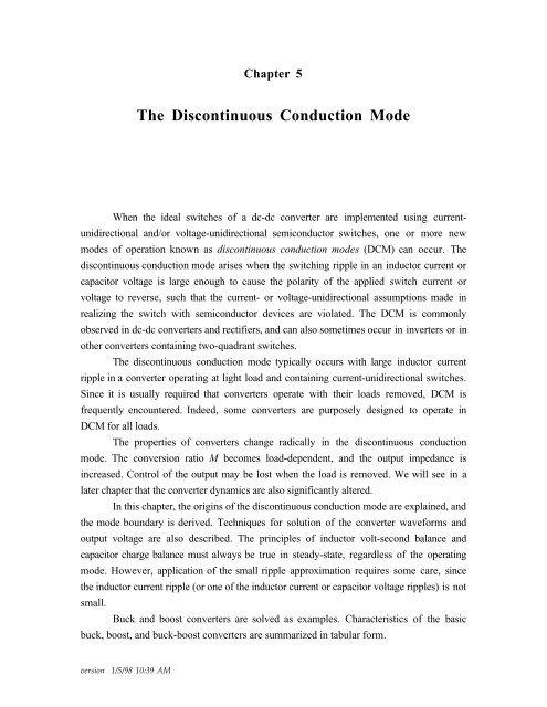
Chapter 5<br />
<strong>The</strong> <strong>Discontinuous</strong> <strong>Conduction</strong> <strong>Mode</strong><br />
When the ideal switches of a dc-dc converter are implemented using currentunidirectional<br />
and/or voltage-unidirectional semiconductor switches, one or more new<br />
modes of operation known as discontinuous conduction modes (DCM) can occur. <strong>The</strong><br />
discontinuous conduction mode arises when the switching ripple in an inductor current or<br />
capacitor voltage is large enough to cause the polarity of the applied switch current or<br />
voltage to reverse, such that the current- or voltage-unidirectional assumptions made in<br />
realizing the switch with semiconductor devices are violated. <strong>The</strong> DCM is commonly<br />
observed in dc-dc converters and rectifiers, and can also sometimes occur in inverters or in<br />
other converters containing two-quadrant switches.<br />
<strong>The</strong> discontinuous conduction mode typically occurs with large inductor current<br />
ripple in a converter operating at light load and containing current-unidirectional switches.<br />
Since it is usually required that converters operate with their loads removed, DCM is<br />
frequently encountered. Indeed, some converters are purposely designed to operate in<br />
DCM for all loads.<br />
<strong>The</strong> properties of converters change radically in the discontinuous conduction<br />
mode. <strong>The</strong> conversion ratio M becomes load-dependent, and the output impedance is<br />
increased. Control of the output may be lost when the load is removed. We will see in a<br />
later chapter that the converter dynamics are also significantly altered.<br />
In this chapter, the origins of the discontinuous conduction mode are explained, and<br />
the mode boundary is derived. Techniques for solution of the converter waveforms and<br />
output voltage are also described. <strong>The</strong> principles of inductor volt-second balance and<br />
capacitor charge balance must always be true in steady-state, regardless of the operating<br />
mode. However, application of the small ripple approximation requires some care, since<br />
the inductor current ripple (or one of the inductor current or capacitor voltage ripples) is not<br />
small.<br />
Buck and boost converters are solved as examples. Characteristics of the basic<br />
buck, boost, and buck-boost converters are summarized in tabular form.
2<br />
Chapter 5. <strong>The</strong> <strong>Discontinuous</strong> <strong>Conduction</strong> <strong>Mode</strong><br />
5.1. Origin of the discontinuous conduction mode, and mode boundary<br />
Let us consider how the inductor<br />
and switch current waveforms change as<br />
Q1 iL (t)<br />
L<br />
the load power is reduced. Let’s use the<br />
buck converter, Fig. 5.1, as a simple<br />
Vg +<br />
–<br />
D1 C R<br />
example. <strong>The</strong> inductor current iL (t) and<br />
iD (t)<br />
diode current iD (t) waveforms are<br />
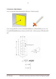
Fig. 5.1. Buck converter example.<br />
sketched in Fig. 5.2 for the continuous<br />
a)<br />
conduction mode. As described in iL (t)<br />
chapter 2, the inductor current waveform<br />
contains a dc component I, plus<br />
switching ripple of peak amplitude ΔiL .<br />
During the second subinterval, the diode<br />
I<br />
ΔiL current is identical to the inductor<br />
0 DTsTs t<br />
current. <strong>The</strong> minimum diode current<br />
conducting<br />
devices: Q1 D1 Q1 during the second subinterval is equal to b)<br />
(I – ΔiL ); since the diode is a single-<br />
iD (t)<br />
quadrant switch, operation in the<br />
continuous conduction mode requires<br />
that this current remain positive. As<br />
shown in chapter 2, the inductor current<br />
I<br />
ΔiL dc component I is equal to the load<br />
current:<br />
0 DTsTs Fig. 5.2. Buck converter waveforms in the<br />
continuous conduction mode: (a) inductor<br />
t<br />
I = V / R (5-1) current iL (t), (b) diode current iD (t).<br />
since no dc current flows through capacitor C. It can be seen that I depends on the load<br />
resistance R. <strong>The</strong> switching ripple peak amplitude is:<br />
ΔiL = (Vg – V)<br />
2L DTs = Vg DD'Ts 2L (5-2)<br />
<strong>The</strong> ripple magnitude depends on the applied voltage (Vg – V), on the inductance L, and on<br />
the transistor conduction time DTs . But it does not depend on the load resistance R. <strong>The</strong><br />
inductor current ripple magnitude varies with the applied voltages rather than the applied<br />
currents.<br />
Suppose now that the load resistance R is increased, so that the dc load current is<br />
decreased. <strong>The</strong> dc component of inductor current I will then decrease, but the ripple<br />
magnitude ΔiL will remain unchanged. If we continue to increase R, eventually the point is<br />
+<br />
V<br />
–
eached where I = ΔiL , illustrated in Fig.<br />
5.3. It can be seen that the inductor current<br />
iL (t) and the diode current iD (t) are both zero<br />
at the end of the switching period. Yet the<br />
load current is positive and non-zero.<br />
What happens if we continue to<br />
increase the load resistance R? <strong>The</strong> diode<br />
current cannot be negative; therefore, the<br />
diode must become reverse-biased before<br />
the end of the switching period. As<br />
illustrated in Fig. 5.4, there are now three<br />
subintervals during each switching period<br />
Ts . During the first subinterval of length<br />
D1Ts the transistor conducts, and the diode<br />
conducts during the second subinterval of<br />
length D2Ts . At the end of the second<br />
subinterval the diode current reaches zero,<br />
and for the remainder of the switching<br />
period neither the transistor nor the diode<br />
conduct. <strong>The</strong> converter operates in the<br />
discontinuous conduction mode.<br />
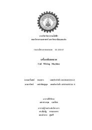
Figure 5.3 suggests a way to find<br />
the boundary between the continuous and<br />
discontinuous conduction modes. It can be<br />
seen that, for this buck converter example,<br />
the diode current is positive over the entire<br />
interval DTs < t < Ts provided that I > ΔiL .<br />
Hence, the conditions for operation in the<br />
continuous and discontinuous conduction<br />
modes are:<br />
I > ΔiL for CCM<br />
I < ΔiL for DCM<br />
(5-3)<br />
where I and ΔiL are found assuming that the<br />
converter operates in the continuous<br />
conduction mode. Insertion of Eqs. (5-1)<br />
3<br />
a)<br />
Chapter 5. <strong>The</strong> <strong>Discontinuous</strong> <strong>Conduction</strong> <strong>Mode</strong><br />
i L (t)<br />
I<br />
0 DTsTs conducting<br />
devices: Q1 D1 Q1 b)<br />
i D (t)<br />
I<br />
ΔiL 0 DTsTs t<br />
Fig. 5.3. Buck converter waveforms at the boundary<br />
between the continuous and discontinuous<br />
conduction modes: (a) inductor current iL (t),<br />
(b) diode current iD (t).<br />
a)<br />
i L (t)<br />
0 DTsTs conducting<br />
D1Ts D2Ts D3Ts devices: Q1 D1 X<br />
b)<br />
i D (t)<br />
I<br />
0 DT s T s<br />
D 2 T s<br />
Fig. 5.4. Buck converter waveforms in the<br />
discontinuous conduction mode: (a) inductor<br />
current i L (t), (b) diode current i D (t).<br />
Q 1<br />
Δi L<br />
t<br />
t<br />
t
and (5-2) into Eq. (5-3) yields the following<br />
condition for operation in the discontinuous<br />
conduction mode:<br />
DVg R < DD'TsVg 2L (5-4)<br />
Simplification leads to<br />
2L < D'<br />
RTs (5-5)<br />
4<br />
Chapter 5. <strong>The</strong> <strong>Discontinuous</strong> <strong>Conduction</strong> <strong>Mode</strong><br />
K crit (D) = 1 – D<br />
0<br />
0 1 D<br />
Fig. 5.5. Buck converter Kcrit (D) vs. D. <strong>The</strong><br />
converter operates in CCM when K ><br />
Kcrit , and in DCM when K < Kcrit .<br />
This can also be expressed<br />
K < K crit(D) for DCM<br />
where K = 2L and K<br />
RT crit(D)=D'<br />
s<br />
(5-6)<br />
<strong>The</strong> dimensionless parameter K is a measure of 2<br />
K > Kcrit :<br />
CCM<br />
the tendency of a converter to operate in the<br />
K = 2L/RTs discontinuous conduction mode. Large values of<br />
K lead to continuous mode operation, while<br />
small values lead to the discontinuous mode for<br />
1<br />
some values of duty cycle. <strong>The</strong> critical value of K<br />
at the boundary between modes, Kcrit (D), is a<br />
Fig. 5.6. Comparison of K with Kcrit (D), for<br />
a larger value of K. Since K > 1, the<br />
function of duty cycle, and is equal to D’ for the<br />
buck converter.<br />
converter operates in CCM for all D.<br />
<strong>The</strong> critical value Kcrit (D) is plotted vs. duty cycle D in Fig. 5.5. An arbitrary choice<br />
of K is also illustrated. For the values shown, it can be seen that the converter operates in<br />
DCM at low duty cycle, and in CCM at high duty cycle. Figure 5.6 illustrates what<br />
happens with heavier loading. <strong>The</strong> load resistance R is reduced in value, such that K is<br />
larger. If K is greater than 1, then the converter operates in the continuous conduction<br />
mode for all duty cycles.<br />
It is natural to express the mode boundary in terms of the load resistance R, rather<br />
than the dimensionless parameter K. Equation (5-6) can be rearranged to directly expose<br />
the dependence of the mode boundary on the load resistance:<br />
R < Rcrit(D) for CCM<br />
R > Rcrit(D) for DCM<br />
where Rcrit(D)= 2L<br />
D'Ts (5-7)<br />
So the converter enters the discontinuous conduction mode when the load resistance R<br />
exceeds the critical value Rcrit . This critical value depends on the inductance, the switching<br />
2<br />
1<br />
K < K crit :<br />
DCM<br />
K crit (D) = 1 – D<br />
K > K crit :<br />
CCM<br />
K = 2L/RT s<br />
0<br />
0 1 D
5<br />
Chapter 5. <strong>The</strong> <strong>Discontinuous</strong> <strong>Conduction</strong> <strong>Mode</strong><br />
period, and the duty cycle. Note that, since D’ ≤ 1, the minimum value of Rcrit is 2L / Ts .<br />
<strong>The</strong>refore, if R < 2L / Ts , then the converter will operate in the continuous conduction<br />
mode for all duty cycles.<br />
<strong>The</strong>se results can be applied to loads which are not pure linear resistors. An<br />
effective load resistance R is defined as the ratio of the dc output voltage to the dc load<br />
current: R = V / I. This effective load resistance is then used in the above equations.<br />
A similar mode boundary analysis can be performed for other converters. <strong>The</strong> boost<br />
converter is analyzed in section 5.3, while analysis of the buck-boost converter is left as a<br />
homework problem. <strong>The</strong> results are listed in Table 5.1, for the three basic dc-dc<br />
converters. In each case, the dimensionless parameter K is defined as K = 2L / RTs , and<br />
the mode boundary is given by<br />
K > K crit(D) or R < R crit(D) for CCM<br />
K < K crit(D) or R > R crit(D) for DCM<br />
Table 5.1. CCM-DCM mode boundaries for the buck, boost, and buck-boost converters<br />
Converter K crit(D)<br />
max<br />
0 ≤ D ≤ 1 ( K crit )<br />
Buck (1 – D) 1<br />
Boost D (1 – D) 2<br />
4<br />
27<br />
Buck-boost (1 – D) 2 1<br />
R crit(D)<br />
2L<br />
(1 – D)T s<br />
2L<br />
D (1 – D) 2 T s<br />
2L<br />
(1 – D) 2 T s<br />
(5-8)<br />
min<br />
0 ≤ D ≤ 1 ( Rcrit )<br />
2 L Ts 27 L<br />
2 Ts<br />
5.2. Analysis of the conversion ratio M(D,K)<br />
With a few modifications, the same techniques and approximations developed in<br />
chapter 2 for the steady-state analysis of the continuous conduction mode may be applied to<br />
the discontinuous conduction mode.<br />
(a) Inductor volt-second balance. <strong>The</strong> dc component of the voltage applied to<br />
an inductor must be zero:<br />
T s<br />
vL = 1 v<br />
T L(t) dt =0<br />
s 0<br />
(5-9)<br />
(b) Capacitor charge balance. <strong>The</strong> dc component of current applied to a<br />
capacitor must be zero:<br />
i C = 1 T s<br />
0<br />
T s<br />
iC(t) dt =0<br />
2 L T s<br />
(5-10)
6<br />
Chapter 5. <strong>The</strong> <strong>Discontinuous</strong> <strong>Conduction</strong> <strong>Mode</strong><br />
<strong>The</strong>se principles must be true for any circuit which operates in steady state,<br />
regardless of the operating mode.<br />
(c) <strong>The</strong> linear ripple approximation. Care must be used when employing the<br />
linear ripple approximation in the discontinuous conduction mode.<br />
(i) Output capacitor voltage ripple. Regardless of the operating<br />
mode, it is required that the output voltage ripple be small. Hence,<br />
for a well-designed converter operating in the discontinuous<br />
conduction mode, the peak output voltage ripple Δv should be much<br />
smaller in magnitude than the output voltage dc component V. So<br />
the linear ripple approximation applies to the output voltage<br />
waveform:<br />
v(t) ≈ V<br />
(5-11)<br />
(ii) Inductor current ripple. By definition, the inductor current ripple<br />
is not small in the discontinuous conduction mode. Indeed, Eq. (5-<br />
3) states that the inductor current ripple ΔiL is greater in magnitude<br />
than the dc component I. So neglecting the inductor current ripple<br />
leads to inaccurate results. In other converters, several inductor<br />
currents, or a capacitor voltage, may contain large switching ripple<br />
which should not be neglected.<br />
<strong>The</strong> equations necessary for solution of the voltage conversion ratio can be obtained by<br />
invoking volt-second balance for each inductor voltage, and charge balance for each<br />
capacitor current, in the network. <strong>The</strong> switching ripple is ignored in the output capacitor<br />
voltage, but the inductor current switching ripple must be accounted for in this buck<br />
converter example.<br />
Let us analyze the conversion ratio M = V / Vg of the buck converter of Fig. 5.1.<br />
When the transistor conducts, for 0 < t < D1Ts , the converter circuit reduces to the network<br />
of Fig. 5.7(a). <strong>The</strong> inductor voltage and capacitor current are given by<br />
vL(t)=Vg – v(t)<br />
iC(t)=iL(t)–v(t)/R (5-12)<br />
By making the linear ripple approximation, to ignore the output capacitor voltage ripple,<br />
one obtains<br />
v L(t) ≈ V g – V<br />
i C(t) ≈ i L(t)–V / R<br />
Note that the inductor current ripple has not been ignored.<br />
(5-13)
<strong>The</strong> diode conducts during subinterval 2,<br />
D1Ts < t < (D1 + D2 )Ts . <strong>The</strong> circuit then reduces to<br />
Fig. 5.7(b). <strong>The</strong> inductor voltage and capacitor<br />
current are given by<br />
vL(t)=–v(t) iC(t)=iL(t)–v(t)/R (5-14)<br />
By neglecting the ripple in the output capacitor<br />
voltage, one obtains<br />
vL(t) ≈ – V<br />
iC(t) ≈ iL(t)–V / R<br />
(5-15)<br />
<strong>The</strong> diode becomes reverse-biased at time t =<br />
(D1 + D2 )Ts . <strong>The</strong> circuit is then as shown in Fig.<br />
5.7(c), with both transistor and diode in the off-state.<br />
<strong>The</strong> inductor voltage and inductor current are both<br />
zero for the remainder of the switching period (D1 +<br />
D2 )Ts < t < Ts . <strong>The</strong> network equations for the third<br />
subinterval are given by<br />
7<br />
Chapter 5. <strong>The</strong> <strong>Discontinuous</strong> <strong>Conduction</strong> <strong>Mode</strong><br />
vL =0, iL =0<br />
iC(t)=iL(t)–v(t)/R (5-16)<br />
Note that the inductor current is constant and<br />
equal to zero during the third subinterval, and<br />
vL (t)<br />
Vg – V<br />
D1Ts D2Ts D3Ts therefore the inductor voltage must also be zero in<br />
accordance with the relation vL (t) = L diL (t)/dt. In<br />
– V<br />
0<br />
Ts practice, parasitic ringing is observed during this<br />
subinterval. This ringing occurs owing to the<br />
Fig. 5.8. Inductor voltage waveform vL (t),<br />
buck converter operating in<br />
resonant circuit formed by the inductor and the<br />
discontinuous conduction mode.<br />
semiconductor device capacitances, and typically has little influence on the converter<br />
steady-state properties. Again ignoring the output capacitor voltage ripple, one obtains<br />
vL(t)=0 iC(t)=–V / R<br />
(5-17)<br />
Equations (5-13), (5-15), and (5-17) can now be used to plot the inductor voltage<br />
waveform as in Fig. 5.8. According to the principle of inductor volt-second balance, the dc<br />
component of this waveform must be zero. Since the waveform is rectangular, its dc<br />
component (or average value) is easily evaluated:<br />
a)<br />
V g<br />
b)<br />
V g<br />
c)<br />
V g<br />
+ –<br />
+ –<br />
+ –<br />
i L (t)<br />
i L (t)<br />
i L (t)<br />
L<br />
+ v L (t) –<br />
L<br />
+ v L (t) –<br />
L<br />
+ v L (t) –<br />
i C (t)<br />
C R<br />
i C (t)<br />
C R<br />
i C (t)<br />
C R<br />
+<br />
v(t)<br />
–<br />
+<br />
v(t)<br />
–<br />
+<br />
v(t)<br />
Fig. 5.7. Buck converter circuits,<br />
(a) during subinterval 1, (b) during<br />
subinterval 2, (c) during subinterval<br />
3.<br />
–<br />
t
v L(t) = D 1(V g – V)+D 2(–V)+D 3(0) = 0<br />
Solution for the output voltage yields<br />
8<br />
Chapter 5. <strong>The</strong> <strong>Discontinuous</strong> <strong>Conduction</strong> <strong>Mode</strong><br />
(5-18)<br />
D1 V = Vg D1 + D2 (5-19)<br />
<strong>The</strong> transistor duty cycle D (which coincides with the subinterval 1 duty cycle D1 ) is the<br />
control input to the converter, and can be considered known. But the subinterval 2 duty<br />
cycle D2 is unknown, and hence another equation is needed to eliminate D2 and solve for<br />
the output voltage V.<br />
L iL (t) v(t)/R<br />
iC (t)<br />
+<br />
<strong>The</strong> second equation is obtained by use of capacitor<br />
charge balance. <strong>The</strong> connection of the capacitor to its<br />
adjacent components is detailed in Fig. 5.9. <strong>The</strong> node<br />
C R v(t)<br />
equation of this network is<br />
Fig. 5.9. Connection of the<br />
output capacitor to<br />
adjacent components.<br />
–<br />
iL(t)=iC(t)+V / R<br />
(5-20)<br />
By capacitor charge balance, the dc component of capacitor<br />
current must be zero:<br />
iC =0<br />
(5-21)<br />
<strong>The</strong>refore, the dc load current must be supplied entirely by the other elements connected to<br />
the node. In particular, for the case of the buck converter, the dc component of inductor<br />
current must be equal to the dc load current:<br />
iL = V / R<br />
(5-22)<br />
So we need to compute the dc component of the inductor current.<br />
Since the inductor current ripple is<br />
not small, determination of the inductor<br />
current dc component requires that we<br />
iL (t)<br />
Vg – V<br />
ipk examine the current waveform in detail.<br />
<strong>The</strong> inductor current waveform is sketched<br />
in Fig. 5.10. <strong>The</strong> current begins the<br />
= I<br />
L<br />
– V<br />
L<br />
switching period at zero, and increases<br />
0<br />
D1Ts DTs D2Ts D3Ts Ts t<br />
during the first subinterval with a constant Fig. 5.10. Inductor current waveform iL (t), buck<br />
slope, given by the applied voltage divided<br />
by the inductance. <strong>The</strong> peak inductor<br />
converter operating in discontinuous conduction<br />
mode.<br />
current ipk is equal to the constant slope, multiplied by the length of the first subinterval:<br />
i L(D 1T s)=i pk = V g – V<br />
L D 1T s<br />
(5-23)
<strong>The</strong> dc component of the inductor current is again the average value:<br />
T s<br />
9<br />
Chapter 5. <strong>The</strong> <strong>Discontinuous</strong> <strong>Conduction</strong> <strong>Mode</strong><br />
iL = 1 i<br />
T L(t) dt<br />
s 0<br />
(5-24)<br />
<strong>The</strong> integral, or area under the iL (t) curve, is the area of the triangle having height ipk and<br />
base dimension (D1 + D2 )Ts . Use of the triangle area formula yields<br />
0<br />
T s<br />
iL(t) dt = 1 2 ipk (D1 + D2)Ts Substitution of Eqs. (5-23) and (5-25) into Eq. (5-24) leads to<br />
(5-25)<br />
iL =(Vg – V) D1Ts 2L (D1 + D2) (5-26)<br />
Finally, by equating this result to the dc load current, according to Eq. (5-22), we obtain<br />
V<br />
=<br />
R D1Ts 2L (D1 + D2)(Vg – V)<br />
(5-27)<br />
Thus, we have two unknowns, V and D2 , and we have two equations. <strong>The</strong> first equation,<br />
Eq. (5-19), was obtained by inductor volt-second balance, while the second equation, Eq.<br />
(5-27), was obtained using capacitor charge balance. Elimination of D2 from the two<br />
equations, and solution for the voltage conversion ratio M(D1 , K) = V / Vg , yields<br />
V<br />
=<br />
Vg 2<br />
2<br />
1+ 1+4K / D1 where K =2L / RTs valid for K < K crit (5-28)<br />
This is the solution of the buck converter operating in discontinuous conduction mode.<br />
<strong>The</strong> complete buck converter characteristics, including both continuous and<br />
discontinuous conduction modes, are therefore<br />
D for K > K crit<br />
M =<br />
2<br />
1+ 1+4K / D 2<br />
for K < K crit<br />
(5-29)<br />
where the transistor duty cycle D is identical to the subinterval 1 duty cycle D1 of the above<br />
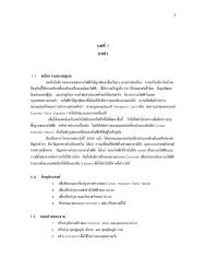
derivation. <strong>The</strong>se characteristics are plotted in Fig. 5.11, for several values of K. It can be<br />
seen that the effect of the discontinuous conduction mode is to cause the output voltage to<br />
increase. As K tends to zero (the unloaded case), M tends to unity for all nonzero D. <strong>The</strong><br />
characteristics are continuous, and Eq. (5-28) intersects the CCM characteristic M = D at<br />
the mode boundary.
1.0<br />
M(D,K)<br />
0.8<br />
0.6<br />
0.4<br />
0.2<br />
0.0<br />
K = 0.01<br />
K = 0.1<br />
K = 0.5<br />
K ≥ 1<br />
10<br />
Chapter 5. <strong>The</strong> <strong>Discontinuous</strong> <strong>Conduction</strong> <strong>Mode</strong><br />
0.0 0.2 0.4 0.6 0.8 1.0<br />
D<br />
Fig. 5.11. Voltage conversion ratio M(D, K), buck converter.<br />
5.3. Boost converter example<br />
As a second example, consider the<br />
i(t) L<br />
D1 iD (t)<br />
boost converter of Fig. 5.12. Let’s<br />
+ vL (t) –<br />
iC (t)<br />
+<br />
determine the boundary between modes,<br />
and solve for the conversion ratio in the<br />
Vg +<br />
–<br />
Q1 C R<br />
discontinuous conduction mode. Behavior<br />
–<br />
of the boost converter operating in the<br />
Fig. 5.12. Boost converter example.<br />
continuous conduction mode was analyzed previously, in section 2.3, and expressions for<br />
the inductor current dc component I and ripple peak magnitude ΔiL were found.<br />
When the diode conducts, its current is identical to the inductor current iL (t). As can<br />
be seen from Fig. 2.18, the minimum value of the inductor current during the diode<br />
conduction subinterval DTs < t < Ts is (I – ΔiL ). If this minimum current is positive, then<br />
the diode is forward-biased for the entire subinterval DTs < t < Ts , and the converter<br />
operates in the continuous conduction mode. So the conditions for operation of the boost<br />
converter in the continuous and discontinuous conduction modes are:<br />
I > ΔiL for CCM<br />
I < ΔiL for DCM<br />
(5-30)<br />
which is identical to the results for the buck converter. Substitution of the CCM solutions<br />
for I and ΔiL , Eqs. (2-39) and (2-43), yields<br />
v(t)
Vg D' 2 R > DTsVg for CCM<br />
2L<br />
This equation can be rearranged to obtain<br />
2L > DD'<br />
RTs 2<br />
which is in the standard form<br />
for CCM<br />
K > K crit(D) for CCM<br />
K < K crit(D) for DCM<br />
where K = 2L<br />
RTs and K crit(D)=DD' 2<br />
<strong>The</strong> conditions for operation in the<br />
continuous or discontinuous conduction<br />
modes are of similar form to those for the<br />
buck converter; however, the critical value<br />
Kcrit (D) is a different function of the duty<br />
cycle D. <strong>The</strong> dependence of Kcrit (D) on the<br />
duty cycle D is plotted in Fig. 5.13. Kcrit (D)<br />
is zero at D = 0 and at D = 1, and has a<br />
maximum value of 4/27 at D = 1/3. Hence,<br />
if K is greater than 4/27, then the converter<br />
operates in the continuous conduction mode<br />
for all D. Figure 5.14 illustrates what<br />
happens when K is less than 4/27. <strong>The</strong><br />
converter then operates in the discontinuous<br />
conduction mode for some intermediate<br />
range of values of D near D = 1/3. But the<br />
converter operates in the continuous<br />
conduction mode near D = 0 and D = 1.<br />
Unlike the buck converter, the boost<br />
converter must operate in the continuous<br />
conduction mode near D = 0 because the<br />
ripple magnitude approaches zero while the<br />
dc component I does not.<br />
Next, let us analyze the conversion<br />
ratio M = V/Vg of the boost converter. When<br />
the transistor conducts, for subinterval 1,<br />
11<br />
K crit (D)<br />
Chapter 5. <strong>The</strong> <strong>Discontinuous</strong> <strong>Conduction</strong> <strong>Mode</strong><br />
0.15<br />
0.1<br />
0.05<br />
0<br />
(5-31)<br />
(5-32)<br />
(5-33)<br />
0 0.2 0.4 0.6 0.8 1<br />
D<br />
K crit( 1 3 ) = 4 27<br />
Fig. 5.13. Boost converter K crit (D) vs. D.<br />
0.15<br />
0.1<br />
0.05<br />
0<br />
CCM<br />
DCM CCM<br />
K < Kcrit K > Kcrit K crit (D)<br />
0 0.2 0.4 0.6 0.8 1<br />
D<br />
Fig. 5.14. Comparison of K with Kcrit (D).<br />
K
0 < t < D1Ts , the converter circuit reduces to<br />
the circuit of Fig. 5.15(a). <strong>The</strong> inductor voltage<br />
and capacitor current are given by<br />
vL(t)=Vg iC(t)=–v(t)/R (5-34)<br />
Use of the linear ripple approximation, to<br />
ignore the output capacitor voltage ripple, leads<br />
to<br />
vL(t) ≈ Vg iC(t) ≈ – V / R<br />
(5-35)<br />
During the second subinterval D1Ts < t < (D1 +<br />
D2 )Ts , the diode conducts. <strong>The</strong> circuit then<br />
reduces to Fig. 5.15(b). <strong>The</strong> inductor voltage<br />
and capacitor current are given by<br />
vL(t)=Vg – v(t)<br />
iC(t)=i(t)–v(t)/R (5-36)<br />
Neglect of the output capacitor voltage ripple<br />
yields<br />
12<br />
Chapter 5. <strong>The</strong> <strong>Discontinuous</strong> <strong>Conduction</strong> <strong>Mode</strong><br />
vL(t) ≈ Vg – V<br />
iC(t) ≈ i(t)–V / R<br />
(5-37)<br />
<strong>The</strong> inductor current ripple has not been neglected.<br />
During the third subinterval, (D1 + D2 )Ts < t < Ts , both transistor and diode are in<br />
the off-state, and Fig. 5.15(c) is obtained. <strong>The</strong> network equations are:<br />
v L =0, i =0<br />
i C(t)=–v(t)/R<br />
Use of the small-ripple approximation yields<br />
vL(t)=0 iC(t)=–V / R<br />
(5-39)<br />
Equations (5-35), (5-37), and (5-39) are<br />
now used to sketch the inductor voltage<br />
waveform as in Fig. 5.16. By volt-second<br />
balance, this waveform must have zero dc<br />
component when the converter operates in<br />
a)<br />
V g<br />
b)<br />
V g<br />
c)<br />
V g<br />
+ –<br />
+ –<br />
+ –<br />
i(t)<br />
i(t)<br />
i(t)<br />
L<br />
+ v L (t) –<br />
L<br />
+ v L (t) –<br />
L<br />
+ v L (t) –<br />
i C (t)<br />
C R<br />
i C (t)<br />
C R<br />
i C (t)<br />
C R<br />
(5-38)<br />
+<br />
v(t)<br />
–<br />
+<br />
v(t)<br />
–<br />
+<br />
v(t)<br />
–<br />
Fig. 5.15. Boost converter circuits, (a) during<br />
subinterval 1, 0 < t < D1Ts , (b) during<br />
subinterval 2, D1Ts < t < (D1 + D2 )Ts ,<br />
(c) during subinterval 3, (D1 + D2 )Ts < t < Ts .<br />
v L (t)<br />
V g<br />
D1Ts D2Ts D3Ts 0<br />
V g – V<br />
Fig. 5.16. Inductor voltage waveform<br />
v L (t), boost converter operating in<br />
discontinuous conduction mode.<br />
T s<br />
t
13<br />
Chapter 5. <strong>The</strong> <strong>Discontinuous</strong> <strong>Conduction</strong> <strong>Mode</strong><br />
steady-state. By equating the average value of this v L (t) waveform to zero, one obtains<br />
D 1V g + D 2(V g – V)+D 3(0) = 0<br />
Solution for the output voltage V yields<br />
(5-40)<br />
V = D1 + D2 Vg D2 (5-41)<br />
<strong>The</strong> diode duty cycle D2 is again an unknown, and so a second equation is needed for<br />
elimination of D2 before the output voltage V can be found.<br />
We can again use capacitor charge balance to obtain the<br />
second equation. <strong>The</strong> connection of the output capacitor to its<br />
D1 iD (t)<br />
iC (t)<br />
+<br />
adjacent components is detailed in Fig. 5.17. Unlike the buck<br />
C R v(t)<br />
converter, the diode in the boost converter is connected to the<br />
output node. <strong>The</strong> node equation of Fig. 5.17 is<br />
–<br />
iD(t)=iC(t)+v(t)/R (5-42)<br />
where iD (t) is the diode current. By capacitor charge balance,<br />
Fig. 5.17. Connection of<br />
the output capacitor to<br />
adjacent components.<br />
the capacitor current iC (t) must have zero dc component in steady-state. <strong>The</strong>refore, the<br />
diode current dc component must be equal to the dc component of the load current:<br />
i D = V / R<br />
(5-43)<br />
So we need to sketch the diode current waveform, and find its dc component.<br />
<strong>The</strong> waveforms of the inductor<br />
current i(t) and diode current iD (t) are<br />
illustrated in Fig. 5.18. <strong>The</strong> inductor current<br />
begins at zero, and rises to a peak value ipk during the first subinterval. This peak value<br />
ipk is equal to the slope Vg / L, multiplied by<br />
the length of the first subinterval, D1Ts :<br />
ipk = Vg L D a)<br />
i(t)<br />
Vg ipk L<br />
Vg – V<br />
L<br />
0<br />
D1Ts DTs D2Ts D3Ts Ts t<br />
1Ts (5-44)<br />
b)<br />
iD (t)<br />
<strong>The</strong> diode conducts during the second<br />
ipk subinterval, and the inductor current then<br />
Vg – V<br />
L<br />
decreases to zero, where it remains during the<br />
third subinterval. <strong>The</strong> diode current iD (t) is<br />
<br />
identical to the inductor current i(t) during the<br />
0<br />
D1Ts DTs D2Ts D3Ts Ts t<br />
second subinterval. During the first and third Fig. 5.18. Boost converter waveforms in the<br />
subintervals, the diode is reverse-biased and<br />
discontinuous conduction mode: (a) inductor<br />
current i(t), (b) diode current iD (t).
hence iD (t) is zero.<br />
<strong>The</strong> dc component of the diode current, , is:<br />
T s<br />
14<br />
Chapter 5. <strong>The</strong> <strong>Discontinuous</strong> <strong>Conduction</strong> <strong>Mode</strong><br />
iD = 1 iD(t) dt<br />
Ts 0<br />
(5-45)<br />
<strong>The</strong> integral is the area under the iD (t) waveform. As illustrated in Fig. 5.18(b), this area is<br />
the area of the triangle having peak value ipk and base dimension D2Ts :<br />
T s<br />
iD(t) dt =<br />
0<br />
1 2 ipk D2Ts (5-46)<br />
Substitution of Eqs. (5-44) and (5-46) into Eq. (5-45) leads to the following expression for<br />
the dc component of the diode current:<br />
iD = 1 1<br />
Ts 2 ipk D2Ts = VgD1D2Ts 2L (5-47)<br />
By equating this expression to the dc load current as in Eq. (5-43), one obtains the final<br />
result<br />
VgD1D2Ts =<br />
2L<br />
V R (5-48)<br />
So now we have two unknowns, V and D2 . We have two equations: Eq. (5-41)<br />
obtained via inductor volt-second balance, and Eq. (5-48) obtained using capacitor charge<br />
balance. Let us now eliminate D2 from this system of equations, and solve for the output<br />
voltage V. Solution of Eq. (5-41) for D2 yields<br />
Vg D2 = D1 V – Vg (5-49)<br />
By inserting this result into Eq. (5-48), and rearranging terms, one obtains the following<br />
quadratic equation:<br />
V 2 – VVg – V 2 2<br />
gD1<br />
K =0<br />
Use of the quadratic formula yields<br />
V<br />
V g<br />
= 1 ± 1+4D 2<br />
1 / K<br />
2<br />
(5-50)<br />
(5-51)<br />
<strong>The</strong> quadratic equation has two roots: one of the roots of Eq. (5-51) is positive, while the<br />
other is negative. We already know that the output voltage of the boost converter should be<br />
positive, and indeed, from Eq. (5-41), it can be seen that V/Vg must be positive since the<br />
duty cycles D1 and D2 are positive. So we should select the positive root:
V<br />
V g<br />
= M(D1,K)= 1+ 1+4D 2<br />
1 / K<br />
2<br />
15<br />
Chapter 5. <strong>The</strong> <strong>Discontinuous</strong> <strong>Conduction</strong> <strong>Mode</strong><br />
(5-52)<br />
where K = 2L / RTs valid for K < Kcrit (D)<br />
This is the solution of the boost converter operating in the discontinuous conduction mode.<br />
<strong>The</strong> complete boost converter characteristics, including both continuous and<br />
discontinuous conduction modes, are<br />
1<br />
for K > K crit<br />
1–D<br />
M =<br />
1+ 1+4D 2 / K<br />
for K < K crit<br />
2<br />
(5-53)<br />
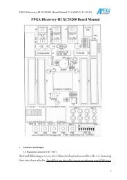
<strong>The</strong>se characteristics are plotted in Fig. 5.19, for several values of K. As in the buck<br />
converter, the effect of the discontinuous conduction mode is to cause the output voltage to<br />
increase. <strong>The</strong> DCM portions of the characteristics are nearly linear, and can be<br />
approximated as<br />
M ≈ 1 2<br />
M(D,K)<br />
+ D<br />
K (5-54)<br />
5<br />
4<br />
3<br />
2<br />
1<br />
0<br />
K = 0.01<br />
K = 0.05<br />
K = 0.1<br />
K ≥ 4/27<br />
0 0.25 0.5 0.75 1<br />
Fig. 5.19. Voltage conversion ratio M(D, K), boost converter.<br />
D
16<br />
Chapter 5. <strong>The</strong> <strong>Discontinuous</strong> <strong>Conduction</strong> <strong>Mode</strong><br />
5.4. Summary of results and key points<br />
<strong>The</strong> characteristics of the basic buck, boost, and buck-boost are summarized in<br />
Table 5.2. Expressions for Kcrit (D), as well as for the solutions of the dc conversion ratios<br />
in CCM and DCM, and for the DCM diode conduction duty cycle D2 , are given.<br />
Table 5.2. Summary of CCM-DCM characteristics for the buck, boost, and buck-boost converters<br />
Converter Kcrit(D) DCM M(D,K) DCM D2(D,K) CCM M(D)<br />
Buck (1 – D)<br />
1+<br />
2<br />
1+4K / D 2<br />
K<br />
D M(D,K) D<br />
Boost D (1 – D) 2 1+ 1+4D 2 / K<br />
2<br />
K<br />
D M(D,K)<br />
1<br />
Buck-boost (1 – D)<br />
1–D<br />
2<br />
– D<br />
K<br />
K<br />
– D<br />
1–D<br />
with K = 2L / RT s. DCM occurs for K < K crit.<br />
<strong>The</strong> dc conversion ratios of the<br />
DCM buck, boost, and buck-boost<br />
converters are compared in Fig. 5.20. <strong>The</strong><br />
buck-boost characteristic is a line with<br />
DCM<br />
M(D,K)<br />
slope 1/ K . <strong>The</strong> characteristics of the<br />
1<br />
buck and the boost converters are both<br />
K<br />
asymptotic to this line, as well as to the line<br />
M = 1. Hence, when operated deeply into<br />
the discontinuous conduction mode, the<br />
boost converter characteristic becomes<br />
1<br />
nearly linear with slope 1/ K , especially 0<br />
at high duty cycle. Likewise, the buck<br />
converter characteristic becomes nearly<br />
D<br />
linear with the same slope, when operated<br />
Fig. 5.20. Comparison of dc conversion ratios of<br />
the buck-boost, buck, and boost converters<br />
deeply into discontinuous conduction mode<br />
at low duty cycle.<br />
operated in discontinuous conduction mode.<br />
<strong>The</strong> following are the key points of this chapter:<br />
1. <strong>The</strong> discontinuous conduction mode occurs in converters containing current- or voltageunidirectional<br />
switches, when the inductor current or capacitor voltage ripple is<br />
large enough to cause the switch current or voltage to reverse polarity.<br />
Boost<br />
Buck-boost (× –1)<br />
Buck<br />
0 0.2 0.4 0.6 0.8 1
17<br />
Chapter 5. <strong>The</strong> <strong>Discontinuous</strong> <strong>Conduction</strong> <strong>Mode</strong><br />
2. Conditions for operation in the discontinuous conduction mode can be found by<br />
determining when the inductor current or capacitor voltage ripples and dc<br />
components cause the switch on-state current or off-state voltage to reverse<br />
polarity.<br />
3. <strong>The</strong> dc conversion ratio M of converters operating in the discontinuous conduction<br />
mode can be found by application of the principles of inductor volt-second and<br />
capacitor charge balance.<br />
4. Extra care is required when applying the small-ripple approximation. Some waveforms,<br />
such as the output voltage, should have small ripple which can be neglected. Other<br />
waveforms, such as one or more inductor currents, may have large ripple that<br />
cannot be ignored.<br />
5. <strong>The</strong> characteristics of a converter changes significantly when the converter enters DCM.<br />
<strong>The</strong> output voltage becomes load-dependent, resulting in an increase in the<br />
converter output impedance.<br />
PROBLEMS<br />
5.1. <strong>The</strong> elements of the buck-boost converter of Fig. 5.21 are ideal: all losses may be ignored. Your<br />
results for parts (a) and (b) should agree with Table 5.2.<br />
V g<br />
+ –<br />
Q 1<br />
i(t)<br />
D 1<br />
L C R<br />
–<br />
Fig. 5.21<br />
a) Show that the converter operates in discontinuous conduction mode when K < Kcrit, and derive<br />
expressions for K and Kcrit. b) Derive an expression for the dc conversion ratio V/Vg of the buck-boost converter operating in<br />
discontinuous conduction mode.<br />
c) For K = 0.1, plot V/Vg over the entire range 0 ≤ D ≤ 1.<br />
d) Sketch the inductor voltage and current waveforms for K = 0.1 and D = 0.3. Label salient<br />
features.<br />
e) What happens to V at no load (R → ∞)? Explain why, physically.<br />
5.2. A certain buck converter contains a synchronous rectifier, as described in section 4.1.5.<br />
a) Does this converter operate in the discontinuous conduction mode at light load? Explain.<br />
b) <strong>The</strong> load resistance is disconnected (R → ∞), and the converter is operated with duty cycle<br />
0.5. Sketch the inductor current waveform.<br />
+<br />
V
18<br />
Chapter 5. <strong>The</strong> <strong>Discontinuous</strong> <strong>Conduction</strong> <strong>Mode</strong><br />
5.3. An unregulated dc input voltage Vg varies over the range 35V ≤ Vg ≤ 70V. A buck converter reduces<br />
this voltage to 28V; a feedback loop varies the duty cycle as necessary such that the converter<br />
output voltage is always equal to 28V. <strong>The</strong> load power varies over the range 10W ≤ Pload ≤<br />
1000W. <strong>The</strong> element values are:<br />
L = 22μH C = 470μF fs = 75kHz<br />
Losses may be ignored.<br />
(a) Over what range of Vg and load current does the converter operate in CCM?<br />
(b) Determine the maximum and minimum values of the steady-state transistor duty cycle.<br />
5.4. <strong>The</strong> transistors in the converter of Fig. 5.22 are driven by the same gate drive signal, so that they<br />
turn on and off in synchronism with duty cycle D.<br />
V g<br />
+ –<br />
Q 2<br />
D 1<br />
L<br />
i(t)<br />
D 2<br />
Q 1<br />
C R<br />
–<br />
Fig. 5.22<br />
(a) Determine the conditions under which this converter operates in the discontinuous conduction<br />
mode, as a function of the steady-state duty ratio D and the dimensionless parameter K =<br />
2L / RTs. (b) What happens for D < 0.5?<br />
(c) Derive an expression for the dc conversion ratio M(D, K). Sketch M vs. D for K = 10 and for<br />
K = 0.1, over the range 0 ≤ D ≤ 1.<br />
V g<br />
+ –<br />
i 1<br />
L 1<br />
+ v C1 –<br />
Q 1<br />
C 1<br />
Fig. 5.23<br />
5.5. DCM mode boundary analysis of the Cuk converter of Fig. 5.23. <strong>The</strong> capacitor voltage ripples are<br />
small.<br />
(a) Sketch the diode current waveform for CCM operation. Find its peak value, in terms of the<br />
ripple magnitudes ΔiL1, ΔiL2, and the dc components I1 and I2, of the two inductor currents<br />
iL1(t) and iL2(t), respectively.<br />
(b) Derive an expression for the conditions under which the Cuk converter operates in the<br />
discontinuous conduction mode. Express your result in the form K < K crit(D), and give<br />
formulas for K and K crit(D).<br />
5.6. DCM conversion ratio analysis of the Cuk converter of Fig. 5.23.<br />
(a) Suppose that the converter operates at the boundary between CCM and DCM, with the<br />
following element and parameter values:<br />
i D<br />
D 1<br />
L 2<br />
C 2<br />
i 2<br />
+<br />
V<br />
R<br />
+<br />
V<br />
–
D = 0.4 fs = 100kHz<br />
Vg = 120 volts R = 10Ω<br />
L1 = 54μH L2 = 27μH<br />
C1 = 47μF C2 = 100μF<br />
19<br />
Chapter 5. <strong>The</strong> <strong>Discontinuous</strong> <strong>Conduction</strong> <strong>Mode</strong><br />
Sketch the diode current waveform iD(t), and the inductor current waveforms i1(t) and i2(t). Label the magnitudes of the ripples and dc components of these waveforms.<br />
(b) Suppose next that the converter operates in the discontinuous conduction mode, with a<br />
different choice of parameter and element values. Derive an analytical expression for the dc<br />
conversion ratio M(D,K).<br />
(c) Sketch the diode current waveform iD(t), and the inductor current waveforms i1(t) and i2(t), for<br />
operation in the discontinuous conduction mode.<br />
V g<br />
+ –<br />
i 1<br />
L1<br />
Q 1<br />
C 1<br />
Fig. 5.24<br />
5.7. DCM mode boundary analysis of the SEPIC of Fig. 5.24<br />
(a) Sketch the diode current waveform for CCM operation. Find its peak value, in terms of the<br />
ripple magnitudes ΔiL1, ΔiL2, and the dc components I1 and I2, of the two inductor currents<br />
iL1(t) and iL2(t), respectively.<br />
(b) Derive an expression for the conditions under which the SEPIC operates in the discontinuous<br />
conduction mode. Express your result in the form K < K crit(D), and give formulas for K<br />
and K crit(D).<br />
5.8. DCM conversion ratio analysis of the SEPIC of Fig. 5.24.<br />
(a) Suppose that the converter operates at the boundary between CCM and DCM, with the<br />
following element and parameter values:<br />
D = 0.4 fs = 100kHz<br />
Vg = 120 volts R = 10Ω<br />
L1 = 50μH L2 = 75μH<br />
C1 = 47μF C2 = 200μF<br />
Sketch the diode current waveform iD(t), and the inductor current waveforms i1(t) and i2(t). Label the magnitudes of the ripples and dc components of these waveforms.<br />
(b) Suppose next that the converter operates in the discontinuous conduction mode, with a<br />
different choice of parameter and element values. Derive an analytical expression for the dc<br />
conversion ratio M(D,K).<br />
(c) Sketch the diode current waveform i D(t), and the inductor current waveforms i 1(t) and i 2(t), for<br />
operation in the discontinuous conduction mode.<br />
i 2<br />
L 2<br />
i D<br />
D 1<br />
C 2<br />
R<br />
+<br />
V<br />
–
20<br />
Chapter 5. <strong>The</strong> <strong>Discontinuous</strong> <strong>Conduction</strong> <strong>Mode</strong><br />
5.9. An L-C input filter is added to a buck converter as illustrated in Fig. 5.25. Inductors L1 and L2 and<br />
capacitor C2 are large in value, such that their switching ripples are small. All losses can be<br />
neglected.<br />
V g<br />
+ –<br />
i1<br />
L 1<br />
C 1<br />
+<br />
v 1<br />
–<br />
Q 1<br />
D 1<br />
Fig. 5.25<br />
(a) Sketch the capacitor C1 voltage waveform v1(t), and derive expressions for its dc component<br />
V1 and peak ripple magnitude ΔvC1. (b) <strong>The</strong> load current is increased (R is decreased in value) such that Δv C1 is greater than V 1.<br />
(i) Sketch the capacitor voltage waveform v 1(t).<br />
(ii) For each subinterval, determine which semiconductor devices conduct.<br />
(iii) Determine the conditions under which the discontinuous conduction mode occurs.<br />
Express your result in the form K < Kcrit(D), and give formulas for K and<br />
Kcrit(D). 5.10. Derive an expression for the conversion ratio M(D,K) of the DCM converter described in the<br />
previous problem. Note: D is the transistor duty cycle.<br />
5.11. In the Cuk converter of Fig. 5.23, inductors L1 and L2 and capacitor C2 are large in value, such that<br />
their switching ripples are small. All losses can be neglected.<br />
(a) Assuming that the converter operates in CCM, sketch the capacitor C1 voltage waveform<br />
vC1(t), and derive expressions for its dc component V1 and peak ripple magnitude ΔvC1. (b) <strong>The</strong> load current is increased (R is decreased in value) such that Δv C1 is greater than V 1.<br />
(i) Sketch the capacitor voltage waveform v C1(t).<br />
(ii) For each subinterval, determine which semiconductor devices conduct.<br />
(iii) Determine the conditions under which the discontinuous conduction mode occurs.<br />
Express your result in the form K < Kcrit(D), and give formulas for K and<br />
Kcrit(D). 5.12. Derive an expression for the conversion ratio M(D,K) of the DCM Cuk converter described in the<br />
previous problem. Note: D is the transistor duty cycle.<br />
5.13. A DCM buck-boost converter as in Fig. 5.21 is to be designed to operate under the following<br />
conditions:<br />
136V ≤ Vg ≤ 204V<br />
5W ≤ P load ≤ 100W<br />
V = – 150V<br />
fs = 100kHz<br />
You may assume that a feedback loop will vary to transistor duty cycle as necessary to maintain a<br />
constant output voltage of – 150V.<br />
i2<br />
L 2<br />
C 2<br />
R<br />
+<br />
v 2<br />
–
21<br />
Chapter 5. <strong>The</strong> <strong>Discontinuous</strong> <strong>Conduction</strong> <strong>Mode</strong><br />
Design the converter, subject to the following considerations:<br />
• <strong>The</strong> converter should operate in the discontinuous conduction mode at all times<br />
• Given the above requirements, choose the element values to minimize the peak inductor<br />
current<br />
• <strong>The</strong> output voltage peak ripple should be less than 1V<br />
Specify:<br />
(a) <strong>The</strong> inductor value L<br />
(b) <strong>The</strong> output capacitor value C<br />
(c) <strong>The</strong> worst-case peak inductor current ipk (d) <strong>The</strong> maximum and minimum values of the transistor duty cycle D.<br />
5.14. A DCM boost converter as in Fig. 5.12 is to be designed to operate under the following conditions:<br />
18V ≤ Vg ≤ 36V<br />
5W ≤ P load ≤ 100W<br />
V = 48V<br />
fs = 150kHz<br />
You may assume that a feedback loop will vary to transistor duty cycle as necessary to maintain a<br />
constant output voltage of 48V.<br />
Design the converter, subject to the following considerations:<br />
• <strong>The</strong> converter should operate in the discontinuous conduction mode at all times. To<br />
ensure an adequate design margin, the discontinuous subinterval length D3Ts should be no<br />
less than ten percent of the switching period Ts, at all operating points.<br />
• Given the above requirements, choose the element values to minimize the peak inductor<br />
current<br />
• <strong>The</strong> output voltage peak ripple should be less than 1V<br />
Specify:<br />
(a) <strong>The</strong> inductor value L<br />
(b) <strong>The</strong> output capacitor value C<br />
(c) <strong>The</strong> worst-case peak inductor current ipk (d) <strong>The</strong> maximum and minimum values of the transistor duty cycle D.<br />
(e) <strong>The</strong> maximum and minimum values of the discontinuous subinterval length D3Ts.
22<br />
Chapter 5. <strong>The</strong> <strong>Discontinuous</strong> <strong>Conduction</strong> <strong>Mode</strong><br />
5.15. In dc-dc converters used in battery-powered portable equipment, it is sometimes required that the<br />
converter continue to regulate its load voltage with high efficiency while the load is in a lowpower<br />
“sleep” mode. <strong>The</strong> power required by the transistor gate drive circuitry, as well as much of<br />
the switching loss, is dependent on the switching frequency but not on the load current. So to<br />
obtain high efficiency at very low load powers, a variable-frequency control scheme can be used, in<br />
which the switching frequency is reduced in proportion to the load current.<br />
a)<br />
V g<br />
i(t)<br />
L<br />
C R<br />
Consider the boost converter system of Fig. 5.26(a). <strong>The</strong> battery pack consists of two<br />
nickel-cadmium cells, which produce a voltage of Vg = 2.4V ± 0.4V. <strong>The</strong> converter boosts this<br />
voltage to a regulated 5V. As illustrated in Fig. 5.26(b), the converter operates in the<br />
discontinuous conduction mode, with constant transistor on-time ton. <strong>The</strong> transistor off-time toff is<br />
varied by the controller to regulate the output voltage.<br />
(a) Write the equations for the CCM-DCM boundary and conversion ratio M = V/Vg, in terms of<br />
ton, toff, L, and the effective load resistance R.<br />
For parts (b) and (c), the load current can vary between 100μA and 1A. <strong>The</strong> transistor on-time is<br />
fixed: t on = 10μs.<br />
(b) Select values for L and C such that:<br />
• <strong>The</strong> output voltage peak ripple is no greater than 50mV,<br />
• <strong>The</strong> converter always operates in DCM, and<br />
• <strong>The</strong> peak inductor current is as small as possible.<br />
(c) For your design of part (b), what are the maximum and minimum values of the switching<br />
frequency?<br />
+<br />
v(t)<br />
battery pack effective load<br />
b) i(t)<br />
t on<br />
i pk<br />
t off<br />
Fig. 5.26<br />
I load<br />
–<br />
t