Vacuum consolidation of thermoplastic composites for ... - DTU Risø
Vacuum consolidation of thermoplastic composites for ... - DTU Risø
Vacuum consolidation of thermoplastic composites for ... - DTU Risø

Create successful ePaper yourself
Turn your PDF publications into a flip-book with our unique Google optimized e-Paper software.
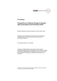
Proceedings <strong>of</strong> the 27 th <strong>Risø</strong> International Symposium<br />
on Materials Science:<br />
Polymer Composite Materials <strong>for</strong> Wind Power Turbines<br />
Editors: H. Lilholt, B. Madsen, T.L. Andersen,<br />
L.P. Mikkelsen, A. Thygesen<br />
<strong>Risø</strong> National Laboratory, Roskilde, Denmark, 2006<br />
VACUUM CONSOLIDATION OF THERMOPLASTIC<br />
COMPOSITES FOR WIND TURBINE ROTOR BLADES<br />
Aage Lystrup<br />
Materials Research Department, <strong>Risø</strong> National Laboratory<br />
DK-4000 Roskilde, Denmark<br />
ABSTRACT<br />
Technology and semi-raw materials <strong>for</strong> vacuum <strong>consolidation</strong> <strong>of</strong> <strong>thermoplastic</strong><br />
<strong>composites</strong> with continuous fibres are discussed, and the potential use <strong>of</strong> this<br />
technology <strong>for</strong> wind turbine blades is demonstrated on a downscaled model.<br />
1. INTRODUCTION<br />
Basically, the vacuum <strong>consolidation</strong> <strong>of</strong> <strong>thermoplastic</strong> composite material is very simple.<br />
All it takes is to vacuum bag the lay-up <strong>of</strong> the semi-raw material, heat it to the process<br />
temperature and cool it back down to room temperature, in order to solidify the matrix<br />
material (Lystrup 1997). Most <strong>thermoplastic</strong> polymers must be (completely) dry and<br />
free <strong>of</strong> absorbed water be<strong>for</strong>e they are melted to avoid degradation caused by reaction<br />
with water. If the material has not been dried prior to the <strong>consolidation</strong> process, a<br />
drying step can be included in the process cycle as illustrated in Fig. 1. The process is<br />
very attractive, since no additional pressure is applied, which means that no autoclave<br />
is needed.<br />
2. MATERIALS AND PROPERTIES<br />
The success <strong>of</strong> this process has been demonstrated on commingled hybrid yarn <strong>of</strong> glass<br />
fibres and PP fibres from Twintex (Twintex 2006), as well <strong>of</strong> glass fibres and L-PET<br />
fibres from Comfil (Comfil 2006). L-PET is a modified low temperature (220 °C)<br />
processing PET. Tension-tension fatigue properties <strong>for</strong> the two materials are shown in<br />
Fig. 2 and compared with glass/PP manufactured from stacked layers <strong>of</strong> glass fibre<br />
fabrics and PP films. The laminates are either made from balanced 0°#90° woven fabric<br />
or from pure UD material (only [0°] fibre orientation), which are more relevant <strong>for</strong><br />
231
Lystrup<br />
wind turbine blades. In all cases, the fibre content is about 40 vol.-%. The fatigue<br />
strength is higher <strong>for</strong> the Twintex material than <strong>for</strong> the Comfil material. It could be<br />
explained by the fact, that the glass fibres in the Twintex material are straighter and<br />
more aligned. The Twintex yarn is manufactured by pulling the glass fibres and<br />
extruding the PP fibres simultaneously. The two types <strong>of</strong> fibres are simply merged,<br />
commingled and spooled in one operation. The Comfil yarn is commingled in an air<br />
texturing process where glass fibres and L-PET fibres are blown into each other to<br />
achieve a thorough commingling, and this causes the glass fibres to be a little wrinkled.<br />
The laminate manufactured by the film stacking technique has lower fatigue strength.<br />
It is due to the presence <strong>of</strong> small voids and few dry glass fibres, especially in the<br />
middle <strong>of</strong> the roving bundles, because it is difficult <strong>for</strong> the molten polymer to penetrate<br />
the roving completely and wet all individual glass fibres. It emphasises the advantages<br />
with commingled yarn and the importance <strong>of</strong> a thorough commingling <strong>of</strong> the two<br />
types <strong>of</strong> fibres.<br />
Shear fatigue properties were measured using short 3-point bending test specimens. As<br />
shown in Fig. 3, the shear fatigue strength is higher <strong>for</strong> the Comfil material that <strong>for</strong> the<br />
Twintex material, indicating higher bond strength between the L-PET matrix and the<br />
glass fibres than between the PP matrix and the fibres, and/or a higher shear strength<br />
<strong>of</strong> the pure L-PET compared to the pure PP.<br />
Temperature [°C]<br />
300<br />
250<br />
200<br />
150<br />
100<br />
50<br />
Oven temperature<br />
Temperatures at<br />
surface <strong>of</strong> laminate<br />
Drying step<br />
Evaporation <strong>of</strong><br />
absorbed water<br />
0<br />
0 1 2 3 4 5 6 7<br />
Time [hour]<br />
Temperature<br />
inside laminate<br />
<strong>Vacuum</strong><br />
Fig. 1. Typical process cycle <strong>for</strong> vacuum <strong>consolidation</strong> <strong>of</strong> <strong>thermoplastic</strong> <strong>composites</strong>. The<br />
maximum process temperature depends on the type <strong>of</strong> <strong>thermoplastic</strong> matrix material.<br />
0<br />
-0.1<br />
-0.2<br />
-0.3<br />
-0.4<br />
-0.5<br />
-0.6<br />
-0.7<br />
-0.8<br />
-0.9<br />
-1<br />
<strong>Vacuum</strong><br />
232
Max stress [MPa]<br />
400<br />
350<br />
300<br />
250<br />
200<br />
150<br />
100<br />
50<br />
<strong>Vacuum</strong> <strong>consolidation</strong> <strong>of</strong> <strong>thermoplastic</strong> <strong>composites</strong><br />
Room Temp.<br />
Tension-Tension Fatigue<br />
Glass fibre / PP (Twintex)<br />
Glass fibre / L-PET (Comfil)<br />
Twintex - 0°#90° - Fabric<br />
PP - Film Stacked<br />
0°#90° - Fabric<br />
1 000 10 000 100 000 1 000 000<br />
Cycles<br />
Twintex - 0°<br />
Comfil - 0°<br />
Comfil - 0°#90° - Fabric<br />
Fig. 2. Tension-tension fatigue properties <strong>of</strong> glass/PP (Twintex) and glass/L-PET<br />
(Comfil) <strong>for</strong> both 0°#90° woven fabric and pure UD fibre orientation. The arrows<br />
indicate tests which were stopped be<strong>for</strong>e the specimen failed.<br />
Shear stress [MPa]<br />
35<br />
30<br />
25<br />
20<br />
Room Temperature Short Beam 3-point Bending Shear Fatigue<br />
Glass fibre / PP<br />
Twintex - 0°<br />
Glass fibre / L-PET<br />
Comfil - 0°<br />
15<br />
10 000 100 000 1 000 000<br />
Cycles<br />
Fig. 3. Shear fatigue properties <strong>of</strong> glass/PP (Twintex) and glass/L-PET (Comfil) with<br />
pure UD fibre orientation.<br />
233
Lystrup<br />
3. PROCESS TECHNOLOGY<br />
3.1 Cycle time. The necessary process temperature can be obtained either by built-in<br />
heating elements in the mould or by heating the entire mould in an oven, and<br />
there<strong>for</strong>e, there are practically no limits to the size <strong>of</strong> the components, which can be<br />
produced. There<strong>for</strong>e, it is also a potential technology <strong>for</strong> large wind turbine rotor<br />
blades, if relatively long process cycle time is acceptable. The maximal laminate<br />
thickness at the root-end section <strong>of</strong> a large rotor blade is expected to be around 100<br />
mm, and the process cycle time <strong>for</strong> such a thick section in glass fibre/PP is about 24<br />
hours, if heated in an oven with circulating hot air, as shown in Fig. 4. The required<br />
process temperature <strong>of</strong> 190 °C in the middle <strong>of</strong> the thickness is reached after 15 hours, if<br />
the temperature <strong>of</strong> the hot air in the oven is 200 °C. These measurements were<br />
per<strong>for</strong>med on a small but thick pyramid shaped test sample as shown in Fig. 5.<br />
Temperature [°C]<br />
200<br />
150<br />
100<br />
50<br />
Oven Temperature<br />
Temperature<br />
at surface <strong>of</strong><br />
laminate<br />
Temperature<br />
in the middle<br />
<strong>of</strong> the laminate<br />
0<br />
0 5 10 15 20 25<br />
Time [hour]<br />
<strong>Vacuum</strong><br />
<strong>consolidation</strong><br />
<strong>of</strong> 100 mm thick<br />
Glass/PP laminate<br />
Fig. 4. Process cycle <strong>for</strong> vacuum <strong>consolidation</strong> <strong>of</strong> a 100 mm thick glass/PP laminate in<br />
an oven with hot-air circulation.<br />
Fig. 5. Pyramid shaped 100 mm thick glass/PP test sample <strong>for</strong> measuring the process<br />
time <strong>for</strong> vacuum <strong>consolidation</strong>. At left: The 250 mm high lay-up with thermocouples<br />
mounted at the top, bottom and inside in the middle <strong>of</strong> the laminate. At right: The 100<br />
mm high consolidated laminate.<br />
234
<strong>Vacuum</strong> <strong>consolidation</strong> <strong>of</strong> <strong>thermoplastic</strong> <strong>composites</strong><br />
3.2 A complete blade in one process step. The assembly <strong>of</strong> a wind turbine blade from<br />
parts is a major task in most current production methods. It is <strong>of</strong> interest to reduce the<br />
number <strong>of</strong> steps in the process, preferably to one, so that a complete blade with webs<br />
etc. is manufactured in one <strong>consolidation</strong> process. This one-step technology is used by<br />
Siemens Wind Power <strong>for</strong> resin infusion <strong>of</strong> fibre composite blades with thermosetting<br />
matrix, but the concept <strong>for</strong> using <strong>thermoplastic</strong> matrix was <strong>of</strong> interest <strong>for</strong> Siemens<br />
Wind Power as well (Brøndsted, Lilholt and Lystrup 2005). Apart from the potential<br />
time saving, it has also the advantage <strong>of</strong> reducing geometric inaccuracies introduced<br />
during the assembly steps.<br />
3.3 Compaction <strong>of</strong> the material. The <strong>consolidation</strong> pressure in vacuum <strong>consolidation</strong> is<br />
limited to only 0.1 MPa. There<strong>for</strong>e, in many cases, it becomes difficult to manufacture<br />
components with complex geometry or sharp internal corners. The low pressure is not<br />
sufficient to con<strong>for</strong>m the material to the mould geometry. A series <strong>of</strong> simple tests in<br />
small moulds have demonstrated this. The geometries <strong>of</strong> the test samples are shown in<br />
Fig. 6. In order to compact a laminate into a mould with a curvature, the inner layers<br />
will need to stretch or “flow”, by an amount proportional to the thickness change and<br />
the curvature. The stretch-ability will depend on the lay-up, the fibre angle and the size<br />
<strong>of</strong> the different fabrics in the laminate. An obvious way <strong>of</strong> improving the stretch<br />
capability <strong>of</strong> a textile is to shrink it. That is effectively to compress the glass fibres<br />
imparting local wrinkles to the fibres, which can be stretched again during the<br />
manufacturing process. The <strong>thermoplastic</strong> fibres in the commingled material are<br />
sensitive to heat, and can be shrunk by the use <strong>of</strong> a hot-air blower. By controlling the<br />
time and temperature, a wide variety <strong>of</strong> shrink ratios can be achieved. The fibre fabrics<br />
are shrunk locally, only where needed, and test has shown that this method is effective.<br />
Fig. 6. Simplified geometries characteristic <strong>for</strong> wind turbine blades used <strong>for</strong><br />
development <strong>of</strong> techniques <strong>for</strong> lay-up and <strong>consolidation</strong> <strong>of</strong> material.<br />
Manufacturing <strong>of</strong> sections simulating the trailing edge <strong>of</strong> a wind turbine blade<br />
demonstrates that it is difficult to get a good <strong>consolidation</strong> in the acute angle. The<br />
vacuum<br />
bag is not able to reach into the very tip <strong>of</strong> the angle, and the flow <strong>of</strong> resin is<br />
extremely limited. Consequently, a certain amount <strong>of</strong> porosity is observed. There<strong>for</strong>e, it<br />
may be necessary to accept a little higher matrix content at certain locations, in order to<br />
entirely fill-up the fibre structure with matrix material, and produce a high quality<br />
material with no or low porosity.<br />
235
Lystrup<br />
The transition from the web to the shells <strong>of</strong> a rotor blade is another challenge.<br />
Simultaneously with the compaction <strong>of</strong> the material in the shells, the material in the<br />
webs must be stretched, and some<br />
means <strong>of</strong> providing a compacting pressure <strong>for</strong> the<br />
shell material in line with the web must be applied. This can be achieved by using PMI<br />
foam, as illustrated in Fig. 7, which is able to re-foam. The foam expands when a<br />
certain temperature is reached, depending <strong>of</strong> the type <strong>of</strong> PMI foam, and provides the<br />
compacting pressure <strong>for</strong> the rein<strong>for</strong>cement. For one quality <strong>of</strong> PMI foam foaming<br />
commences at around 200 °C. The amount <strong>of</strong> additional expansion and pressure<br />
depends on time, temperature and constrained conditions. This technique can also help<br />
solving the problem at the trailing edge.<br />
Fig. 7. Test <strong>of</strong> technique using expanding foam to consolidate material at difficult<br />
geometries. At left: Transition from the web to the shell. At right: Trailing edge.<br />
3.4 Handling and lay-up <strong>of</strong> materials in the mould. The geometry <strong>of</strong> the finished blade,<br />
with a length over 40 m and a weight <strong>of</strong> several tonnes, puts severe limits to how the<br />
manufacturing<br />
can be done. Test on a short section (0.5 m) <strong>of</strong> a turbine blade has<br />
shown that a combination <strong>of</strong> outside female and temporary inside male moulds is very<br />
promising. The material <strong>for</strong> one side <strong>of</strong> the blade is placed in a bottom female mould.<br />
Webs, vacuum bag material, and the temporary male mould parts are then placed in<br />
the female mould on top <strong>of</strong> the laid-up material, and the material <strong>for</strong> the "top" shell is<br />
placed on the male mould sections, as shown in Fig. 8. Then the mould is closed by a<br />
second female mould, the vacuum bags are sealed to the mould, and a vacuum<br />
sufficient to hold the material in place is drawn between the vacuum bags and the<br />
mould surface. The temporary male mould sections used to hold the fibre materials in<br />
place during lay-up are removed, and the wing section is ready <strong>for</strong> <strong>consolidation</strong>, as<br />
shown in Fig. 9, together with various types <strong>of</strong> finished test sections. Temporary male<br />
mould parts made from s<strong>of</strong>t foam are very convenient, especially when the different<br />
parts are enclosed in individual vacuum bags. The stiffness <strong>of</strong> the foam parts is<br />
sufficient to support the material and hold it in place during lay-up and sealing<br />
procedure, and by pulling a slight vacuum on a bag containing a foam section, its<br />
236
<strong>Vacuum</strong> <strong>consolidation</strong> <strong>of</strong> <strong>thermoplastic</strong> <strong>composites</strong><br />
volume is reduced drastically, which facilitates the removal <strong>of</strong> the male mould part<br />
from the female mould. The female mould is made <strong>of</strong> Aluminium. It is light, easily<br />
manufactured, and conducts heat well.<br />
Fig. 8. Lay-up <strong>of</strong> material in one-half <strong>of</strong> a female mould using temporary male moulds<br />
to support the materials, which later will be pressed towards the other half <strong>of</strong> the<br />
female mould. The glass/PP fabrics at the far left <strong>of</strong> the picture are folded to the top <strong>of</strong><br />
the lay-up be<strong>for</strong>e the top-female mould is placed and assembled with the bottom<br />
female mould.<br />
Fig. 9. At left: The completed vacuum bagged<br />
lay-up test section with two webs in<br />
place ready to be heated and consolidated. At right: Various types <strong>of</strong> finished test<br />
sections.<br />
4 CONCLUSIONS<br />
The potential use <strong>of</strong> vacuum <strong>consolidation</strong> <strong>of</strong> <strong>thermoplastic</strong> <strong>composites</strong> <strong>for</strong> wind<br />
turbine blades has been demonstrated.<br />
The process technology <strong>for</strong> making a complete wind turbine blade in one process step<br />
has been developed.<br />
237
Lystrup<br />
The fatigue properties <strong>of</strong> two types <strong>of</strong> semi-raw materials have been investigated. That<br />
is commingled glass fibres and PP fibres from Twintex, and glass fibres and L-PET<br />
fibres from Comfil.<br />
The Twintex material has the highest tension-tension fatigue strength, whereas the<br />
Comfil material has the highest shear fatigue strength.<br />
The process cycle time <strong>for</strong> vacuum <strong>consolidation</strong> <strong>of</strong> a 100 mm thick laminate is about 24<br />
hours. That is what it takes to heat up the centre <strong>of</strong> the laminate to the process<br />
temperature <strong>of</strong> about 190 °C, and to cool it back down to room temperature in an oven<br />
with circulating air.<br />
The laid-up fabrics must be able to stretch in order to obtain full compaction <strong>of</strong> the<br />
material into a concave<br />
curvature. Stretchable fabric was created by pre-shrinking it<br />
prior to lay-up. The shrinking can be done by heating the fabric, because the polymer<br />
fibres shrink when heated. The location and amount <strong>of</strong> shrinking were easily controlled<br />
by the use <strong>of</strong> a hand-hold hot-air blower.<br />
Compaction <strong>of</strong> the material into the sharp tip <strong>of</strong> the trailing edge and <strong>of</strong> the shell<br />
laminate, where the webs are connected to the shell, can be achieved by the use <strong>of</strong><br />
foam, which expands when heated to the process temperature.<br />
A technique <strong>for</strong> placing and vacuum bagging all the fabrics <strong>for</strong> a complete blade,<br />
including webs, inside a female mould has been developed and demonstrated. The<br />
laid-up fabrics are temporary supported by s<strong>of</strong>t-foam male mould parts, which are<br />
removed after the female mould is closed and the material is hold in place by the<br />
vacuum.<br />
ACKNOWLEDGEMENTS<br />
Thanks to Siemens Wind Power A/S, Denmark, <strong>for</strong> the collaboration within this work,<br />
EU-JOULE program <strong>for</strong> financial support, and B. S. Johansen, <strong>Risø</strong> National<br />
Laboratory, <strong>for</strong> planning and conducting a part <strong>of</strong> the work.<br />
REFERENCES<br />
Brøndsted, P., Lilholt, H., and Lystrup A. (2005). Composite materials <strong>for</strong> wind power<br />
turbine blades. Annual Review <strong>of</strong> Materials Research, 35,<br />
505-538.<br />
Comfil (2006). http://www.comfil.biz<br />
Lystrup, A. (1997). Processing technology <strong>for</strong> advanced fibre <strong>composites</strong> with<br />
<strong>thermoplastic</strong> matrices. 18 th <strong>Risø</strong> International Symposium on Materials Science 1997<br />
– Polymeric Composites – Expanding<br />
the Limits, <strong>Risø</strong>, Denmark, 69-80.<br />
Twintex (2006). http://www.twintex.com/<br />
238