
You also want an ePaper? Increase the reach of your titles
YUMPU automatically turns print PDFs into web optimized ePapers that Google loves.
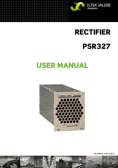
<strong>USER</strong> <strong>MANUAL</strong><br />
<strong>RECTIFIER</strong><br />
<strong>PSR327</strong><br />
UM_<strong>PSR327</strong>_21TE_E_R5.0
Rectifier<br />
<strong>PSR327</strong><br />
User Manual<br />
Page 2 (20)<br />
Notes to this manual<br />
ATTENTION! Read this manual very carefully before installing and commissioning the specified module.<br />
This manual is a part of the delivered module. Familiarity with the contents of this manual is required for<br />
installing and operating the specified module.<br />
The rules for prevention of accidents for the specific country and the general safety rules in accordance<br />
with IEC 364 must be observed.<br />
The function description in this manual corresponds to the date of publishing.<br />
Technical changes and changes in form and content can be made at any time by the manufacturer<br />
without notice. There are no obligations to update the manual continually.<br />
The module is manufactured in accordance with applicable DIN and VDE standards such as VDE 0106<br />
(part 100) and VDE 0100 (part 410). The CE marking on the module confirms compliance with EU<br />
standards 2006-95-EG (low voltage) and 2004-108-EG (electromagnetic compatibility) if the installation<br />
and operation instructions are followed.<br />
Supplier:<br />
ELTEK VALERE DEUTSCHLAND GmbH<br />
GB Industrial<br />
Schillerstraße 16<br />
D-32052 Herford<br />
+ 49 (0) 5221 1708-210<br />
FAX + 49 (0) 5221 1708-222<br />
Email Info.industrial@eltekvalere.com<br />
Internet http://www.eltekvalere.com<br />
2009. ELTEK VALERE DEUTSCHLAND GmbH. All rights reserved.<br />
©2009. ELTEK VALERE DEUTSCHLAND GmbH. UM_<strong>PSR327</strong>_21TE_ E_R5.0
Rectifier<br />
<strong>PSR327</strong><br />
User Manual<br />
Page 3 (20)<br />
The current revision status of this user manual is the following:<br />
Revision: 5.0<br />
Date: 2009-07-24<br />
Revision Description of change Writer Date<br />
00 First edition RTH 2007-11-06<br />
01 Minor text modifications RTH 2008-01-04<br />
02<br />
Minor text modifications, sections “Commissioning”, “Output<br />
power diagram” and “Monitoring” reworked<br />
RTH 2008-04-10<br />
1.3<br />
Minor text modifications, “Index of figures” inserted, new<br />
revision status numbering (X.X) introduced.<br />
RTH 2008-11-03<br />
2.0<br />
Section 4.2.1 “Start-up behaviour” inserted; Technical<br />
specifications: Adjustable output voltage range changed.<br />
RTH 2009-04-29<br />
3.0 Section 4.5 “Monitoring” reworked. RTH 2009-05-15<br />
4.0<br />
Minor text modifications, section 4.7 “Default value setting<br />
for NiCd batteries” inserted.<br />
RTH 2009-07-07<br />
5.0<br />
Technical specifications: “Internal decoupling circuit”<br />
corrected.<br />
RTH 2009-07-24<br />
©2009. ELTEK VALERE DEUTSCHLAND GmbH. UM_<strong>PSR327</strong>_21TE_ E_R5.0
Rectifier<br />
<strong>PSR327</strong><br />
User Manual<br />
Page 4 (20)<br />
Table of Contents<br />
1A. Safety Instructions.......................................................................................................................5<br />
1B. Electric Waste Disposal ...............................................................................................................5<br />
2. General Information ........................................................................................................................6<br />
3. Type Range/Equipment .................................................................................................................6<br />
3.1 Main Data .....................................................................................................................................................................6<br />
3.2 Available Options and Assembly Equipment.......................................................................................................7<br />
3.3 Front view/Front side LED panel ............................................................................................................................8<br />
3.4 Rear Side Connection ................................................................................................................................................9<br />
3.5 Cooling and Air Flow Direction.............................................................................................................................. 10<br />
3.6 Communication Interface...................................................................................................................................... 10<br />
4. Handling .......................................................................................................................................... 11<br />
4.1 Storage ...................................................................................................................................................................... 11<br />
4.2 Commissioning......................................................................................................................................................... 11<br />
4.2.1 Start-up behavior ............................................................................................................................................. 11<br />
4.3 Charge Characteristic/Output Power Diagram ............................................................................................... 12<br />
4.4 LED Indications......................................................................................................................................................... 13<br />
4.5 Internal Monitoring.................................................................................................................................................. 13<br />
4.6 Threshold & Default Values.................................................................................................................................. 14<br />
4.7 Default value setting for NiCd batteries ........................................................................................................... 14<br />
5. External Functions........................................................................................................................ 15<br />
6. Maintenance .................................................................................................................................. 15<br />
7. Troubleshooting............................................................................................................................ 16<br />
8. Technical Specifications ............................................................................................................. 17<br />
8.1 Dimensional Drawings ............................................................................................................................................ 19<br />
Index of Figures<br />
Figure 1) DC Power Rack DCR <strong>PSR327</strong>-8.1 ....................................................................................................................7<br />
Figure 2) DC Power Rack DCR <strong>PSR327</strong>-10.8..................................................................................................................7<br />
Figure 3) Front view..............................................................................................................................................................8<br />
Figure 4) Male connectors..................................................................................................................................................9<br />
Figure 5) Module air flow.................................................................................................................................................. 10<br />
Figure 6) Output power diagram (example <strong>PSR327</strong>/48-56)................................................................................... 12<br />
Figure 7) Screenshot “PC software for CAN-Dongle” ............................................................................................... 14<br />
Figure 8) Module dimensions .......................................................................................................................................... 19<br />
©2009. ELTEK VALERE DEUTSCHLAND GmbH. UM_<strong>PSR327</strong>_21TE_ E_R5.0
Rectifier<br />
<strong>PSR327</strong><br />
User Manual<br />
Page 5 (20)<br />
1A. Safety Instructions<br />
Warning!<br />
Because several components of operating electrical modules are charged by dangerous voltage, the<br />
improper handling of electrical modules may be the cause of accidents involving electrocution, injury, or<br />
material damages.<br />
Operation and maintenance of electrical modules must be performed by qualified skilled<br />
personnel such as electricians in accordance with EN 50110-1 or IEC 60950.<br />
Install the module only in areas with limited access to unskilled personnel.<br />
Before starting work, the electrical module must be disconnected from mains. Make sure that<br />
the module is earthed.<br />
Do not touch connector pins as they can be charged with dangerous voltage up to 30 seconds<br />
after disconnection.<br />
Only spare parts approved by the manufacturer must be used.<br />
1B. Electric Waste Disposal<br />
Separate collection is the precondition to ensure specific treatment and recycling of waste electrical and electronic<br />
equipment and is necessary to achieve the chosen level of protection of human health and the environment.<br />
In the case of waste disposal of your discarded equipment we recommend to contact a waste management<br />
company.<br />
©2009. ELTEK VALERE DEUTSCHLAND GmbH. UM_<strong>PSR327</strong>_21TE_ E_R5.0
Rectifier<br />
<strong>PSR327</strong><br />
User Manual<br />
Page 6 (20)<br />
2. General Information<br />
The <strong>PSR327</strong> rectifier rectifies sinusoidal AC input voltage to DC output voltage.<br />
The <strong>PSR327</strong> is a hot plug-in module with rear side connectors and is designed to be mounted in an<br />
assembly set 19’’ sub rack (see section 3.2). Due to the state-of-the-art circuitry design, the unit has<br />
very low losses and therefore very compact dimensions, low weight and high power density.<br />
The <strong>PSR327</strong> rectifier can be used in all DC applications with or without battery.<br />
The rectifier is delivered with factory set default values for lead acid batteries. If the rectifier is to be<br />
used for NiCd batteries, the default values must be parameterized accordingly using a CAN dongle and<br />
special software.<br />
The nominal output power per unit is 2700 W. Up to a maximum of 48 modules can be switched in<br />
parallel to increase the system output power or to build redundant power supply systems (n + 1principle).<br />
3. Type Range/Equipment<br />
Type Designation Material Code Nominal Output Voltage Nominal Output Current<br />
<strong>PSR327</strong>/48-56 101-027-158.00 48VDC 56ADC<br />
<strong>PSR327</strong>/60-45 101-027-168.00 60VDC 45ADC<br />
<strong>PSR327</strong>/110-25 101-027-178.00 108VDC 25ADC<br />
<strong>PSR327</strong>/220-12.5 101-027-188.00 216VDC 12.5ADC<br />
3.1 Main Data<br />
Nominal input voltage: 230VAC<br />
Nominal input current: 12.9AAC<br />
Input frequency: 47- 63Hz<br />
Nominal output power 2700W<br />
For more specific data, see section 8.<br />
©2009. ELTEK VALERE DEUTSCHLAND GmbH. UM_<strong>PSR327</strong>_21TE_ E_R5.0
Rectifier<br />
<strong>PSR327</strong><br />
User Manual<br />
Page 7 (20)<br />
3.2 Available Options and Assembly Equipment<br />
Designation Material Code<br />
DC Power Rack DCR <strong>PSR327</strong>-8.1 LV (assembly set 19’’ sub rack 3U<br />
incl. backplane for three <strong>PSR327</strong>/48V or 60V rectifiers and one<br />
UPC3-48/60V DC controller), DCC-CB1 connection board included.<br />
DC Power Rack DCR <strong>PSR327</strong>-8.1 HV (assembly set 19’’ sub rack 3U<br />
incl. backplane for three <strong>PSR327</strong>/110V or 220V rectifiers and one<br />
UPC3-110V or 220V DC controller), DCC-CB1 connection board<br />
included.<br />
DC Power Rack DCR <strong>PSR327</strong>-10.8 LV (assembly set 19’’ sub rack 3U<br />
incl. backplane for four <strong>PSR327</strong>/48V or 60V rectifiers).<br />
DC Power Rack DCR <strong>PSR327</strong>-10.8 HV (assembly set 19’’ sub rack 3U<br />
incl. backplane for four <strong>PSR327</strong>/110V or 220V rectifiers).<br />
Cover plate (with handle) to cover empty PSR slots, 1/4 x 19’’, 3U;<br />
RAL 7035<br />
102-327-318.LV01<br />
102-327-318.HV01<br />
102-327-408.LV01<br />
102-327-408.HV01<br />
881-MEC-BPL.03.21.B<br />
Monitoring, control and signalling unit (DC controller) UPC3-48/60V 301-003-598.02<br />
Monitoring, control and signalling unit (DC controller) UPC3-110V 301-003-798.02<br />
Monitoring, control and signalling unit (DC controller) UPC3-220V 301-003-898.02<br />
DCC-CB1; connection board (with MSTB screw terminals) necessary<br />
to connect all measuring, control and signalling wires over the<br />
backplane of the sub rack to the control unit UPC3 (spare part).<br />
CAN dongle, incl. PC software; necessary to change the internal<br />
default values of the rectifier (e.g. for NiCd application).<br />
Figure 1) DC Power Rack DCR <strong>PSR327</strong>-8.1 fully<br />
equipped with three <strong>PSR327</strong> rectifiers<br />
and one UPC3 DC controller<br />
302-DCC-CB1.00<br />
880-CAN-DNG.00<br />
Figure 2) DC Power Rack DCR <strong>PSR327</strong>-10.8 fully<br />
equipped with four <strong>PSR327</strong> rectifiers<br />
©2009. ELTEK VALERE DEUTSCHLAND GmbH. UM_<strong>PSR327</strong>_21TE_ E_R5.0
Rectifier<br />
<strong>PSR327</strong><br />
User Manual<br />
Page 8 (20)<br />
3.3 Front view/Front side LED panel<br />
Figure 3) Front view<br />
The <strong>PSR327</strong> rectifier is equipped with the<br />
following four LED indicators:<br />
INPUT OK<br />
OUTPUT OK<br />
Vout><br />
ALARM<br />
For more information about the LED indicators,<br />
see section 4.4<br />
Two captive screws are used for each module to<br />
secure it to the sub rack (components of the<br />
module)<br />
©2009. ELTEK VALERE DEUTSCHLAND GmbH. UM_<strong>PSR327</strong>_21TE_ E_R5.0
Rectifier<br />
<strong>PSR327</strong><br />
User Manual<br />
Page 9 (20)<br />
3.4 Rear Side Connection<br />
The rear side male connections (AC input voltage, DC output voltage and signals) are shown in figure 4)<br />
and are defined in the table below.<br />
Figure 4) Male connectors (shown from the rear side of the module)<br />
Pin assignment of the rear side connector:<br />
Pin Function<br />
2b L1 - Input<br />
5b N - Input<br />
8b - - -<br />
11b PE<br />
13a CAN - CVSS<br />
13c (-) output voltage sense link<br />
14a CAN - H<br />
14c CAN - L<br />
15a - - -<br />
15c CAN - CVCC<br />
16a AGND<br />
16c - - -<br />
17a Hardwarecoding CODE2<br />
17c Hardwarecoding CODE1<br />
18a Collective Alarm NC<br />
18c Collective Alarm COM<br />
19a Collective Alarm NO<br />
19c - - -<br />
20a - - -<br />
20c (+) output voltage sense link<br />
22b (-) Output<br />
25b (-) Output<br />
28b (+) Output<br />
31b (+) Output<br />
©2009. ELTEK VALERE DEUTSCHLAND GmbH. UM_<strong>PSR327</strong>_21TE_ E_R5.0
Rectifier<br />
<strong>PSR327</strong><br />
User Manual<br />
Page 10 (20)<br />
3.5 Cooling and Air Flow Direction<br />
The unit is cooled with an internal fan. The airflow is from the front to rear side. The fan is monitored and<br />
speed-controlled dependent on module temperature. To provide sufficient air flow, a minimum space<br />
(see item “A” in figure 5) of 50 mm is required between the unit and the rear cabinet wall as well as an<br />
unobstructed supply of air to the front of the module.<br />
Figure 5) Module air flow<br />
3.6 Communication Interface<br />
The <strong>PSR327</strong> rectifier is equipped with a serial data interface in accordance with the Controller Area<br />
Network (CAN) specification. The CAN-Bus connection is integrated in the rear side connector.<br />
Several modules in a system or parallel connection can be controlled and monitored through the CAN-<br />
Bus by a central UPC3 DC controller unit.<br />
The following parameters of a specific rectifier unit can be controlled or monitored:<br />
Output voltage<br />
Output current<br />
Device temperature<br />
Device status<br />
Furthermore, the rectifier unit receives all threshold values through the CAN-Bus from the<br />
DC controller unit.<br />
©2009. ELTEK VALERE DEUTSCHLAND GmbH. UM_<strong>PSR327</strong>_21TE_ E_R5.0
Rectifier<br />
<strong>PSR327</strong><br />
User Manual<br />
Page 11 (20)<br />
4. Handling<br />
4.1 Storage<br />
Modules must be stored in a dry, dust free environment with a storage temperature in accordance with<br />
the specific technical data (see section 8).<br />
4.2 Commissioning<br />
Note: Before commissioning the module, make sure that the input voltage corresponds to the input<br />
voltage range of the unit as specified on the type plate and that the output voltage of paralleled units<br />
matches.<br />
1. Carefully unpack the unit<br />
2. Fill the rack beginning with the left slot.<br />
3. Put the unit into an empty slot.<br />
4. Carefully slide in the unit until the module connector touched the backplane connector.<br />
5. Increase the force until the unit fits in completely. Avoid using too much force. If the unit does not<br />
fit in, begin again at step 3.<br />
6. Secure the module using the two captive screws (M3x12) provided with the module.<br />
7. Switch ON the module by external MCB.<br />
Note: The <strong>PSR327</strong> is serially equipped with an internal output side decoupling diode. This ensures<br />
hot plug-in capability for the module and enables the operator to add modules under operating<br />
conditions.<br />
Note: Before a module is to be removed, it must be switched off by the external input fuse!<br />
Caution: After switching off the module the internal capacitors are still fully charged. Do not touch<br />
connector pins as they can still be charged with dangerous voltage after disconnection.<br />
4.2.1 Start-up behavior<br />
When the <strong>PSR327</strong> is switched on (without CAN-Bus connection) first it provides a start-up voltage<br />
according to the table below. The start-up voltage is held for 60 seconds, than the output voltage steps<br />
up to the internal default value.<br />
<strong>PSR327</strong> 48V version 60V version 110V version 220V version<br />
Start-up voltage (VDC) 45.0 55.5 97.5 192.0<br />
Default value Vo (VDC) 54.5 68.1 122.6 245.2<br />
If a DC controller unit (UPC3) is integrated into the system, it is powered with the start-up voltage after<br />
the rectifier has been switched on. The output voltage immediately steps up to the value given from the<br />
UPC3 unit via CAN-Bus.<br />
If a DC controller unit (UPC3) is integrated into the system (e.g. powered by the battery and due to this<br />
operating yet) the rectifier directly provides the output voltage given from the UPC3 unit via CAN-Bus.<br />
©2009. ELTEK VALERE DEUTSCHLAND GmbH. UM_<strong>PSR327</strong>_21TE_ E_R5.0
Rectifier<br />
<strong>PSR327</strong><br />
User Manual<br />
Page 12 (20)<br />
4.3 Charge Characteristic/Output Power Diagram<br />
The charge characteristic of the <strong>PSR327</strong> is a power limited IV characteristic curve in accordance with<br />
DIN 41772/DIN 41773.<br />
For modules in parallel operation mode a load sharing of about ±10% is attained due to a sloping output<br />
voltage line (-1% at 100% Inom).<br />
The module is continuously short circuit proof.<br />
Figure 6) Output power diagram (example <strong>PSR327</strong>/48-56)<br />
Calculation of the output current (Io) at different output voltage values using the <strong>PSR327</strong>/48-65 being<br />
the example:<br />
The <strong>PSR327</strong> rectifier provides an output power of Vonom x Ionom= Ponom (48V x 56.25A= 2700W).<br />
As shown with the output power diagram (see figure 6), the nominal output current (56.25A) is available<br />
at the nominal output voltage (48.0V).<br />
At other output voltage values (e.g. float or boost charge voltage), the output current is corresponding<br />
to the following formula: Io= Ponom : Vo<br />
Example 1):<br />
Float charge voltage for lead acid batteries (24 cells) = 54.5V; Io= 2700W : 54.5V= 49.5A<br />
Example 2):<br />
Boost charge voltage for lead acid batteries (24 cells) = 57.6V; Io= 2700W : 57.6V= 46.9A<br />
©2009. ELTEK VALERE DEUTSCHLAND GmbH. UM_<strong>PSR327</strong>_21TE_ E_R5.0
Rectifier<br />
<strong>PSR327</strong><br />
User Manual<br />
Page 13 (20)<br />
4.4 LED Indications<br />
Functions of front panel LED indicators<br />
LED Colour Function<br />
green<br />
INPUT OK - Mains input voltage okay<br />
(criteria: 195VAC ≤Vn ≤265VAC)<br />
green OUTPUT OK - Vout ok (criteria: Vout ≥97% of adjusted value)*<br />
red Vout > (criteria: Vout ≥ than adjusted operating threshold)*<br />
red<br />
ALARM - Collective alarm**: Vin incorrect, Vout incorrect, module<br />
overtemperature, fan failure and short circuit<br />
*For factory set output voltage threshold values, see section 4.6<br />
**The module is equipped with an isolated signalling contact (normally open contact).<br />
The maximum load is 60VDC/500mA. The contact is time-delayed and reacts after approx. 10 sec.<br />
4.5 Internal Monitoring<br />
Monitored values Criteria Function<br />
I.) Mains input voltage 164V≤ Vn≤ 195V Linearly decreases output power.<br />
II.) Mains input voltage 184V<br />
Module switches on.<br />
IV.) Mains input voltage >275V<br />
Module switches off (self-locking). It<br />
must be manually restarted.<br />
DC output voltage<br />
Output voltage higher than the<br />
adjusted operating threshold*<br />
Module automatically switches off (self<br />
locking). The unit must be manually<br />
restarted.<br />
Module<br />
temperature<br />
Heat sink temperature ≥80°C<br />
Module automatically switches off. It<br />
automatically switches on when the<br />
heat sink cools down to ≤70°C.<br />
Module automatically switches off.<br />
After 30 sec. the module automatically<br />
Cooling fan Cooling fan malfunction<br />
tries three times to restart. If this fails,<br />
the module switches off and must be<br />
manually restarted.<br />
Short circuit<br />
Module automatically detects short<br />
circuit operation by the output voltage<br />
value. (criteria: Vout ≤83% of Vnom)<br />
Module automatically switches off after<br />
3 seconds. After 30 seconds the<br />
module automatically tries to restart<br />
repeatedly.<br />
*For factory set output voltage threshold values, see section 4.6<br />
©2009. ELTEK VALERE DEUTSCHLAND GmbH. UM_<strong>PSR327</strong>_21TE_ E_R5.0
Rectifier<br />
<strong>PSR327</strong><br />
User Manual<br />
Page 14 (20)<br />
4.6 Threshold & Default Values<br />
The following table shows the factory set threshold/default values internally stored in the <strong>PSR327</strong> unit<br />
(for lead acid batteries):<br />
Default values 48V version 60V version 110V version 220V version<br />
Output voltage Vo (VDC) 54.5 68.1 122.6 245.2<br />
Over voltage V> (VDC) 60.0 75.0 135.0 270.0<br />
Current limiting Iconst (ADC) 56.0 45.0 25.0 12.5<br />
Note: The threshold/default values can only be changed in combination with a UPC3 DC controller unit.<br />
If an UPC3 DC controller unit is controlling the power supply unit through the CAN-Bus, the charge<br />
voltage is completely controlled by the UPC3 based on its configuration values and momentary charge<br />
state (for example temperature compensation, boost charge, or battery test). That means that the<br />
values sent from the UPC over CAN-Bus have top priority. During CAN-Bus communication the internally<br />
stored values of the rectifier are invalid.<br />
But when the CAN-Bus connection is inactive for more than five seconds (e. g. due to trouble), the<br />
<strong>PSR327</strong> automatically switches back to the internally stored default values. In this case it is ensured<br />
that the battery is charged in the float charge mode.<br />
4.7 Default value setting for NiCd batteries<br />
If the rectifier is to be used to charge NiCd batteries the default/threshold values must be set according<br />
to the individual battery type using a CAN dongle and PC software (see section 3.2 “Available Options<br />
and Assembly Equipment”). A specific manual is available on request. For the adjusting range of the<br />
output voltage please see section 8 “Technical Specifications”.<br />
Figure 7) Screenshot “PC software for CAN-Dongle”<br />
©2009. ELTEK VALERE DEUTSCHLAND GmbH. UM_<strong>PSR327</strong>_21TE_ E_R5.0
Rectifier<br />
<strong>PSR327</strong><br />
User Manual<br />
Page 15 (20)<br />
5. External Functions<br />
If the rectifier works together with a UPC3 DC controller unit, the following external functions can be<br />
used:<br />
Compensation of output voltage<br />
Temperature compensation of charge voltage<br />
Discharge test<br />
Boost charge mode<br />
For more information about these functions, read the UPC3 user manual.<br />
6. Maintenance<br />
In general, the rectifier is maintenance-free. Exclusively the fan is a component consisting of moving<br />
parts. By way of precaution a yearly inspection with following checks is recommended:<br />
Mechanical/visual inspection<br />
Removal of dust and dirt, especially on radiator surfaces<br />
Check for internal dust or humidity<br />
It is recommended to exchange the fan every five years.<br />
Attention! Dust combined with moisture or water may influence or destroy the internal electronic<br />
circuits.<br />
Dust inside the unit can be blown out with dry compressed air.<br />
The interval between the checks depends on ambient conditions of the installed module.<br />
©2009. ELTEK VALERE DEUTSCHLAND GmbH. UM_<strong>PSR327</strong>_21TE_ E_R5.0
Rectifier<br />
<strong>PSR327</strong><br />
User Manual<br />
Page 16 (20)<br />
7. Troubleshooting<br />
Symptom Possible reason Corrective action<br />
No output<br />
voltage<br />
Is mains voltage present?<br />
Check<br />
Mains switched to “ON” position? Check<br />
Deviation of the<br />
output voltage<br />
<strong>PSR327</strong> module plugged in securely?<br />
Incorrect polarity or short circuit at the output?<br />
Check<br />
Check<br />
LED V> on? 1.) Switch the module off and on.<br />
2.) Check the settings for<br />
V> (see section 4.6).<br />
Is the unit operating in current limiting mode Reduce the load<br />
due to overload?<br />
Is the output voltage setting Vout at the DC<br />
controller incorrect?<br />
If an external sensor lead is used for the output<br />
voltage, is the connection faultless?<br />
Adjust output voltage to nominal<br />
values (see section 4.6)<br />
Check<br />
If the module still does not work even though all checks have been done, contact your sales agent or the<br />
ELTEK VALERE DEUTSCHLAND service department.<br />
©2009. ELTEK VALERE DEUTSCHLAND GmbH. UM_<strong>PSR327</strong>_21TE_ E_R5.0
Rectifier<br />
<strong>PSR327</strong><br />
User Manual<br />
Page 17 (20)<br />
8. Technical Specifications<br />
Type designation <strong>PSR327</strong>/48-56 <strong>PSR327</strong>/60-45 <strong>PSR327</strong>/110-25 <strong>PSR327</strong>/220-12.5<br />
Material code 101-027-158.00 101-027-168.00 101-027-178.00 101-027-188.00<br />
AC input:<br />
Nominal input voltage 230VAC ±20% <br />
Nominal input current 12.9AAC <br />
Input frequency range 47- 63Hz <br />
Power factor >0.99 @ P >50%<br />
Total harmonic distortion <br />
(factory set, 2.5V/cell; lead<br />
acid battery*)<br />
Output under voltage Vo<<br />
(factory set, 1.7V/cell; lead<br />
acid battery*)<br />
42 – 62VDC 52.5 – 78VDC<br />
54.5VDC 68.1VDC<br />
87 – 150VDC<br />
122.6VDC<br />
170– 295VDC<br />
245.2VDC<br />
60VDC 75VDC 135VDC 270VDC<br />
40.8VDC 51VDC 91.8VDC 183.6VDC<br />
*Default/threshold values for charging of NiCd batteries are settable using a CAN dongle and PC software.<br />
Voltage ripple / psophometric<br />
acc. to CCITT-A<br />
Dynamic accuracy of the<br />
charge voltage<br />
≤20mVpp/<br />
≤ 1.8mV<br />
≤20mVpp/<br />
≤2.0mV<br />
≤100mVpp/<br />
n/a<br />
Rectifier<br />
<strong>PSR327</strong><br />
User Manual<br />
Page 18 (20)<br />
Type designation <strong>PSR327</strong>/48-56 <strong>PSR327</strong>/60-45 <strong>PSR327</strong>/110-25 <strong>PSR327</strong>/220-12.5<br />
Parallel operation Yes (max. 48 units with UPC3 DC controller unit);<br />
current sharing ≤10% Inom; sloping output voltage line (-1% at 100% Inom)<br />
Internal decoupling at the<br />
output<br />
Yes; active, lowloss<br />
decoupling<br />
circuit in the<br />
negative output<br />
line<br />
Yes, in the<br />
positive output<br />
line<br />
Internal output fuse 80A 80A 30A 20A<br />
Standard Features:<br />
LED signalling Input OK (green), Vo OK (green), Vo> (red), Alarm (red)<br />
Main processor 16Bit Fujitsu <br />
Isolated signalling contact “Collective alarm”; relay COM/NO/NC, maximum contact load: 60VDC/500mA<br />
Communications interface CAN-Bus, proprietary protocol<br />
Environmental:<br />
Ambient temperature Operation: -20°C to +55°C, storage: -40°C to +85°C<br />
Climatic conditions according to IEC 721-3-3 class 3K3/3Z1/3B1/3C2/3S2/3M2<br />
Max. installation altitude ≤ 1500m<br />
Audible noise
Rectifier<br />
<strong>PSR327</strong><br />
User Manual<br />
Page 19 (20)<br />
8.1 Dimensional Drawings<br />
Figure 8) Module dimensions<br />
©2009. ELTEK VALERE DEUTSCHLAND GmbH. UM_<strong>PSR327</strong>_21TE_ E_R5.0
Supplier:<br />
ELTEK VALERE DEUTSCHLAND GmbH<br />
GB Industrial<br />
Schillerstraße 16<br />
D-32052 Herford<br />
+ 49 (0) 5221 1708-210<br />
FAX + 49 (0) 5221 1708-222<br />
Email Info.industrial@eltekvalere.com<br />
Internet http://www.eltekvalere.com<br />
2009. ELTEK VALERE DEUTSCHLAND GmbH. All rights reserved.