
Create successful ePaper yourself
Turn your PDF publications into a flip-book with our unique Google optimized e-Paper software.
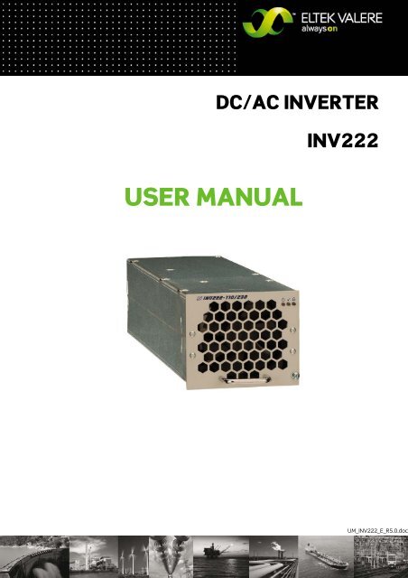
DC/AC INVERTER<br />
USER MANUAL<br />
<strong>INV222</strong><br />
<strong>UM</strong>_<strong>INV222</strong>_E_R5.0.doc
DC/AC Inverter<br />
<strong>INV222</strong><br />
User Manual<br />
Page 2 (20)<br />
Notes on this manual<br />
ATTENTION! Read this manual very carefully before installing and commissioning the specified module.<br />
This manual is a part of the delivered module. Familiarity with the contents of this manual is required for installing<br />
and operating the specified module.<br />
The rules for prevention of accidents for the specific country and the general safety rules in accordance with IEC<br />
364 must be observed.<br />
The function description in this manual corresponds to the date of publishing.<br />
Technical changes and changes in form and content can be made at any time by the manufacturer without notice.<br />
There are no obligations to update the manual continually.<br />
The module is manufactured in accordance with applicable DIN and VDE standards such as VDE 0106 (part 100) and<br />
VDE 0100 (part 410). The CE marking on the module confirms compliance with EU standards 2006-95-EG (low voltage)<br />
and 2004/108/EG (electromagnetic compatibility) if the installation and operation instructions are followed.<br />
Supplier:<br />
ELTEK VALERE DEUTSCHLAND GmbH<br />
GB Industrial<br />
Schillerstraße 16<br />
D-32052 Herford<br />
+ 49 (0) 5221 1708-210<br />
FAX + 49 (0) 5221 1708-222<br />
Email Info.industrial@eltekvalere.com<br />
Internet http://www.eltekvalere.com<br />
Changes and errors excepted.<br />
2009. ELTEK VALERE DEUTSCHLAND GmbH. All rights reserved.<br />
©2009. ELTEK VALERE DEUTSCHLAND GmbH. <strong>UM</strong>_<strong>INV222</strong>_E_R5.0.doc
DC/AC Inverter<br />
<strong>INV222</strong><br />
User Manual<br />
Page 3 (20)<br />
The current revision status of this user manual is the following:<br />
Revision: 5.0<br />
Date: 2010-04-13<br />
Revision Description of change Writer Date<br />
00 First edition RTH 2007-10-24<br />
01 Section “Commissioning” reworked, minor text modifications RTH 2008-03-17<br />
02 Section “Trouble shooting” reworked RTH 2008-04-08<br />
03 Index of Figures inserted RTH 2008-04-15<br />
04 Figure 1 & 2: Minor modifications<br />
Tables “LED indications” and “Monitoring” completed, section<br />
RTH 2008-04-23<br />
1.0 “Technical Data” modified, new revision status numbering (X.X)<br />
introduced.<br />
RTH 2009-01-15<br />
2.0 Input voltage value of the 60V version updated. RTH 2009-02-05<br />
3.0 View of the rear side connector corrected. RTH 2009-04-08<br />
4.0 Section 8) „External input fuses“ reworked. RTH 2009-06-25<br />
5.0 Appendix "Three-phase application" inserted. RTH 2010-04-13<br />
©2009. ELTEK VALERE DEUTSCHLAND GmbH. <strong>UM</strong>_<strong>INV222</strong>_E_R5.0.doc
DC/AC Inverter<br />
<strong>INV222</strong><br />
User Manual<br />
Page 4 (20)<br />
TABLE OF CONTENTS<br />
1. SAFETY INSTRUCTIONS.................................................................................................................................................5<br />
2. ELECTRIC WASTE DISPOSAL.........................................................................................................................................5<br />
3. GENERAL INFORMATION................................................................................................................................................6<br />
3.1 TYPICAL APPLICATIONS ..................................................................................................................................................6<br />
4. TYPE RANGE/EQUIPMENT ............................................................................................................................................7<br />
4.1 MAIN DATA ....................................................................................................................................................................7<br />
4.2 AVAILABLE OPTIONS AND ASSEMBLY EQUIPMENT............................................................................................................8<br />
4.3 FRONT VIEW/FRONT LED PANEL ....................................................................................................................................9<br />
4.4 REAR SIDE CONNECTION .............................................................................................................................................. 10<br />
4.5 MODULE COOLING ....................................................................................................................................................... 11<br />
4.6 COMMUNICATION INTERFACE....................................................................................................................................... 11<br />
5. HANDLING...................................................................................................................................................................... 12<br />
5.1 STORAGE .................................................................................................................................................................... 12<br />
5.2 COMMISSIONING.......................................................................................................................................................... 12<br />
5.3 LED INDICATIONS........................................................................................................................................................ 12<br />
5.4 MONITORING ............................................................................................................................................................... 13<br />
6. MAINTENANCE ............................................................................................................................................................. 13<br />
7. TROUBLE SHOOTING................................................................................................................................................... 14<br />
8. TECHNICAL SPECIFICATIONS..................................................................................................................................... 15<br />
8.1 DIMENSIONAL DRAWINGS............................................................................................................................................. 17<br />
APPENDIX: THREE-PHASE APPLICATION .................................................................................................................... 18<br />
YOUR NOTES ..................................................................................................................................................................... 19<br />
Index of Figures<br />
Figure 1. Inverter in parallel operation without STS........................................................................................6<br />
Figure 2. Inverter in parallel operation with STS..............................................................................................6<br />
Figure 3. AC Rack ACR <strong>INV222</strong>-6.75.................................................................................................................8<br />
Figure 4. AC Rack ACR <strong>INV222</strong>-9.0...................................................................................................................8<br />
Figure 5. Front view ...........................................................................................................................................9<br />
Figure 6. Male connectors...............................................................................................................................10<br />
Figure 7. Air flow direction ..............................................................................................................................11<br />
Figure 8. Module dimensions ..........................................................................................................................17<br />
©2009. ELTEK VALERE DEUTSCHLAND GmbH. <strong>UM</strong>_<strong>INV222</strong>_E_R5.0.doc
DC/AC Inverter<br />
<strong>INV222</strong><br />
User Manual<br />
Page 5 (20)<br />
1. Safety Instructions<br />
WARNING!<br />
Because several components of operating electrical modules are charged by dangerous voltage, the improper<br />
handling of electrical modules may be the cause of accidents involving electrocution, injury, or material damages.<br />
Operation and maintenance of electrical modules must be performed by qualified skilled personnel such as<br />
electricians in accordance with EN 50110-1 or IEC 60950-1.<br />
Install the module only in areas with limited access to unskilled personnel.<br />
Before starting work, the electrical module must be disconnected from mains. Make sure that the module<br />
is earthed.<br />
Do not touch connector pins as they can be charged with dangerous voltage up to 30 seconds after<br />
disconnection.<br />
Only spare parts approved by the manufacturer must be used.<br />
2. Electric Waste Disposal<br />
Separate collection is the precondition to ensure specific treatment and recycling of waste electrical and electronic<br />
equipment and is necessary to achieve the chosen level of protection of human health and the environment.<br />
In the case of waste disposal of your discarded equipment we recommend to contact a waste management company.<br />
©2009. ELTEK VALERE DEUTSCHLAND GmbH. <strong>UM</strong>_<strong>INV222</strong>_E_R5.0.doc
DC/AC Inverter<br />
<strong>INV222</strong><br />
User Manual<br />
Page 6 (20)<br />
3. General information<br />
The inverter <strong>INV222</strong> converts input side DC voltage to a stable sine wave output voltage.<br />
The <strong>INV222</strong> is a module with rear side connectors and is designed to be mounted in an assembly set sub rack<br />
(see section 4.2).<br />
The inverter is controlled and monitored by internal microprocessors. Due to its state-of-the-art circuitry design,<br />
the unit has very low losses and therefore very compact dimensions, low weight and a very high power density.<br />
To increase the reliability the inverter is designed to operate together with a static transfer switch of series<br />
STS207. The static transfer switch monitors the connected bypass mains and synchronizes the inverter output<br />
with mains frequency. In inverter priority mode the STS transfers the load supply to bypass mains in case of inverter<br />
faults, high overload or battery low voltage. The transfer is nearly without voltage interruption (
DC/AC Inverter<br />
<strong>INV222</strong><br />
User Manual<br />
Page 7 (20)<br />
4. Type range/equipment<br />
4.1 Main data<br />
Type Designation Article Code<br />
Nominal Input<br />
Voltage<br />
Nominal Input<br />
Current<br />
Input Voltage<br />
Range<br />
(VIMIN - VIMAX)<br />
<strong>INV222</strong>-48/230-50 501-022-515.00 48VDC 41.6ADC 40.8- 67.5VDC<br />
<strong>INV222</strong>-60/230-50 501-022-615.00 60VDC 33.3ADC 52- 76VDC<br />
<strong>INV222</strong>-110/230-50 501-022-715.00 108VDC 18.4ADC 91.8- 135VDC<br />
<strong>INV222</strong>-220/230-50 501-022-815.00 216VDC 9.2ADC 183.6- 270VDC<br />
Nominal output values:<br />
Output Voltage: 230VAC<br />
Output Current: 9.8AAC @ power factor 0.8; 7.8AAC @ power factor 1.0 (resistive)<br />
Output Frequency: 50/60Hz<br />
For more specific data, see section 8.<br />
REMARK: For article codes of <strong>INV222</strong> for three-phase application, please see Appendix.<br />
©2009. ELTEK VALERE DEUTSCHLAND GmbH. <strong>UM</strong>_<strong>INV222</strong>_E_R5.0.doc
DC/AC Inverter<br />
<strong>INV222</strong><br />
User Manual<br />
Page 8 (20)<br />
4.2 Available options and assembly equipment<br />
Designation Material code<br />
AC Rack ACR <strong>INV222</strong>-6.75 LV (assembly set 19” sub 502-222-315.LV<br />
rack 2U including a wired backplane for max. three<br />
<strong>INV222</strong>-48 or <strong>INV222</strong>-60 and one static transfer switch<br />
STS207)<br />
AC Rack ACR <strong>INV222</strong>-6.75 HV (assembly set 19” sub 502-222-315.HV<br />
rack 2U including a wired backplane for max. three<br />
<strong>INV222</strong>-110 or <strong>INV222</strong>-220 and one static transfer<br />
switch STS207)<br />
AC Rack ACR <strong>INV222</strong>-9.0 LV (assembly set 19” sub rack 502-222-405.LV<br />
2U including a wired backplane for max. four <strong>INV222</strong>-48<br />
or <strong>INV222</strong>-60)<br />
AC Rack ACR <strong>INV222</strong>-9.0 HV (assembly set 19” sub rack 502-222-405.HV<br />
2U including a wired backplane for max. four <strong>INV222</strong>-<br />
110 or <strong>INV222</strong>-220)<br />
Cover plate (with handle), necessary to cover empty<br />
slots, 2U, colour RAL 7035<br />
Figure 3. AC Rack ACR <strong>INV222</strong>-6.75 fully equipped<br />
with three inverters <strong>INV222</strong> and<br />
one static transfer switch STS207<br />
881-MEC-BPL.02.21.B<br />
Figure 4. AC Rack ACR <strong>INV222</strong>-9.0 fully equipped<br />
with four inverters <strong>INV222</strong><br />
©2009. ELTEK VALERE DEUTSCHLAND GmbH. <strong>UM</strong>_<strong>INV222</strong>_E_R5.0.doc
DC/AC Inverter<br />
<strong>INV222</strong><br />
User Manual<br />
Page 9 (20)<br />
4.3 Front view/front LED panel<br />
Figure 5. Front view<br />
The <strong>INV222</strong> is fitted with the<br />
following three LED indicators:<br />
OPERATION<br />
OUTPUT OK<br />
ALARM<br />
For more information about the LED indicators, see<br />
section 5.3 and section 7.<br />
One captive screw is used for each module to secure it<br />
to the sub rack (component of the module).<br />
©2009. ELTEK VALERE DEUTSCHLAND GmbH. <strong>UM</strong>_<strong>INV222</strong>_E_R5.0.doc
DC/AC Inverter<br />
<strong>INV222</strong><br />
User Manual<br />
Page 10 (20)<br />
4.4 Rear side connection<br />
The rear side male connections (DC input voltage, AC output voltage and signals) are shown in figure 6.) and are<br />
defined in the following table:<br />
Table: Pin assignment of the rear side male connector:<br />
Pin Designation<br />
22b, 25b DC input, plus pole<br />
28b, 31b DC input, minus pole<br />
11b PE<br />
5b AC output, Neutral<br />
2b AC output, Phase L1<br />
15a Alarm NC<br />
16c Alarm COM<br />
19c SYNC-STAT1 (synchronization bus 1, state lines)<br />
20a SYNC-SIG1 (synchronization bus 1, 50Hz-signal)<br />
18c SYNC-STAT2 (synchronization bus 2, state lines)<br />
19a SYNC-SIG2 (synchronization bus 2, 50Hz-signal)<br />
20c SYNC-GND (synchronization bus, ground)<br />
14a CAN-H<br />
14c CAN-L<br />
13a CAN-VSS<br />
15c CAN-VCC<br />
17c Address coding<br />
16a AGND<br />
Figure 6. Male connectors (shown from the rear side of the module)<br />
©2009. ELTEK VALERE DEUTSCHLAND GmbH. <strong>UM</strong>_<strong>INV222</strong>_E_R5.0.doc
DC/AC Inverter<br />
<strong>INV222</strong><br />
User Manual<br />
Page 11 (20)<br />
4.5 Module cooling<br />
The unit is cooled with an internal fan. The airflow is from the front to rear side. The fan is monitored and speed-<br />
controlled dependent on module temperature. To provide sufficient air flow, a minimum space (see item “A” at<br />
figure 7.) of 50mm is required between the unit and the rear cabinet wall as well as an unobstructed supply of air.<br />
Figure 7. Air flow direction<br />
4.6 Communication interface<br />
The inverter is equipped with a serial data interface in accordance with the Controller Area Network<br />
(CAN) specification. The CAN-Bus connection is integrated in the rear side connector.<br />
Several inverters in a system or parallel connection can be controlled and monitored through the CAN-Bus by a<br />
central unit which is integrated in the static transfer switch unit STS.<br />
The following parameters of a specific inverter unit can be controlled or monitored:<br />
Inverter status (OK/failure)<br />
Output voltage (measurement value)<br />
Output current (TRMS measurement value)<br />
Input voltage (measurement value)*<br />
Input current (measurement value)*<br />
Output frequency (measurement value)*<br />
Internal temperature (measurement value)*<br />
*with separate software tool<br />
©2009. ELTEK VALERE DEUTSCHLAND GmbH. <strong>UM</strong>_<strong>INV222</strong>_E_R5.0.doc
DC/AC Inverter<br />
<strong>INV222</strong><br />
User Manual<br />
Page 12 (20)<br />
5. Handling<br />
5.1 Storage<br />
The modules must be stored in a dry, dust free environment with a storage temperature in accordance with the<br />
specific technical data (see section 8).<br />
5.2 Commissioning<br />
Note: Before commissioning the module, make sure that the input voltage corresponds to the nominal input<br />
voltage of the unit as specified on the type plate.<br />
1. Carefully unpack the unit<br />
2. Fill the rack beginning with the left slot.<br />
3. Put the unit into an empty slot.<br />
4. Carefully slide in the unit until the module connector touched the backplane connector.<br />
5. Increase the force until the unit fits in completely. Avoid using too much force. If the unit does not fit in,<br />
begin again at Step 3.<br />
6. Secure the unit using the captive screw (M4x12) provided with the module.<br />
Note: Before removing a module it must be switched off by the external input fuse!<br />
WARNING: After switching off the module the internal capacitors are still fully charged. Do not touch connector<br />
pins as they can still be charged with dangerous voltage after disconnection.<br />
5.3 LED indications<br />
Functions of front panel LED indicators<br />
LED Colour Function<br />
Green OPERATION - Inverter operation; DC input voltage monitoring<br />
Green<br />
OUTPUT OK - Output voltage monitoring<br />
Red Collective Alarm*<br />
The following faults result in a collective alarm message:<br />
Input voltage high or low<br />
Output voltage high or low<br />
Short circuit or over load<br />
Internal temperature higher than specified value<br />
Fan failure<br />
*The module is equipped with an isolated signalling contact (NC). The maximum load is 60VDC/100mA.<br />
For more information about the fault status and flashing patterns of the red LED see section 7.<br />
©2009. ELTEK VALERE DEUTSCHLAND GmbH. <strong>UM</strong>_<strong>INV222</strong>_E_R5.0.doc
DC/AC Inverter<br />
<strong>INV222</strong><br />
User Manual<br />
Page 13 (20)<br />
5.4 Monitoring<br />
Monitoring functions<br />
Monitored values Criteria Function<br />
DC input voltage<br />
AC output voltage<br />
Input voltage out of the range of factory<br />
set input voltage range VIMIN* and VIMAX*<br />
Output voltage out of the specified<br />
range of Vo< and Vo><br />
Vo< = 190V<br />
Vo> = 253V<br />
Short circuit Io>130% Inom (9.8A)<br />
Overload<br />
Temperature<br />
Io>Inom (9.8A)<br />
Po>Pnom (1800W/2250VA)<br />
Internal temperature higher than<br />
specified value*<br />
1.) At VIMIN: Module automatically<br />
switches off and on with delay and<br />
hysteresis.<br />
2.) At VIMAX: Immediately switch off.<br />
1.) At Vo: Module automatically switches<br />
off. The module must be manually<br />
restarted.<br />
Module automatically switches off after<br />
three seconds. The module automatically<br />
tries three times to restart. If this fails, the<br />
module switches off and must be manually<br />
restarted.<br />
Module automatically switches off after 10<br />
seconds. The module must be manually<br />
restarted.<br />
Automatically switch-off at high over temperature<br />
and switch-on with hysteresis<br />
Fan speed N< 500min -1 Automatically switch-off<br />
* see specific technical data section (section 8)<br />
6. Maintenance<br />
In general, the module is maintenance free.<br />
A yearly inspection with the following checks is recommended:<br />
Mechanical inspection<br />
Removal of dust and dirt, especially on radiator surfaces<br />
Check for internal dust or humidity<br />
WARNING! Dust combined with moisture or water may influence or destroy the internal electronic circuits.<br />
Dust inside the unit can be blown out with dry compressed air.<br />
The interval between the checks depends on ambient conditions of the installed module.<br />
©2009. ELTEK VALERE DEUTSCHLAND GmbH. <strong>UM</strong>_<strong>INV222</strong>_E_R5.0.doc
DC/AC Inverter<br />
<strong>INV222</strong><br />
User Manual<br />
Page 14 (20)<br />
7. Trouble shooting<br />
The following table shows all possible combinations of LED signals on the inverter unit.<br />
The LED symbols mean:<br />
Grey = LED off<br />
Green or red = LED permanently on<br />
Green or red with rays = LED is flashing<br />
LED signal Possible reason Corrective action<br />
1. No DC input voltage<br />
1. - Check input DC voltage<br />
- Check incoming distribution fuses<br />
- Check mounting position of the module<br />
2. Internal fault on circuitry<br />
2. Exchange the unit<br />
Inverter was remotely switched off via<br />
CAN-Bus<br />
Check the STS controller for the reason of<br />
the switch-off command<br />
DC input voltage low or high Check DC input voltage level<br />
Normal operation mode<br />
Device switched off due to error<br />
1. Restart the unit by switching on the input<br />
DC fuse<br />
2. If the fault remains, exchange the unit<br />
Output voltage low Internal fault in circuitry; exchange the unit<br />
Active Error Warning<br />
The following four errors are indicated:<br />
1. Overload or short circuit<br />
2. Fan fault<br />
3. Over temperature<br />
4. Output voltage high<br />
The module automatically switches off with time<br />
delay. Active errors are indicated with the following<br />
flashing patterns of the red LED:<br />
Active error Flashing pattern<br />
1. Overload or short circuit<br />
2. Fan fault<br />
3. Over temperature<br />
4. Output voltage high<br />
1. Reduce the load to nominal value (see section<br />
7) or check the load circuitry for short circuit<br />
2. Exchange the unit or the internal fan<br />
(service personnel only)<br />
3. Check all air ventilations; remove dirt and dust;<br />
check the environment temperature<br />
(see the values at section 8)<br />
4. Internal fault in circuitry; exchange the unit<br />
If the module still does not work even though all checks have been done, contact your sales agent or the ELTEK<br />
VALERE DEUTSCHLAND service department.<br />
©2009. ELTEK VALERE DEUTSCHLAND GmbH. <strong>UM</strong>_<strong>INV222</strong>_E_R5.0.doc
DC/AC Inverter<br />
<strong>INV222</strong><br />
User Manual<br />
Page 15 (20)<br />
8. Technical specifications<br />
Type designation: <strong>INV222</strong>- 48/230-50 60/230-50 110/230-50 220/230-50<br />
Article code 501-022-515.00 501-022-615.00 501-022-715.00 501-022-815.00<br />
Article codes of <strong>INV222</strong> for three-phase application: See Appendix.<br />
DC input:<br />
Nominal input voltage 48VDC 60VDC 108VDC 216VDC<br />
Input voltage range (VIMIN-VIMAX) 40.8-67.5VDC 52-76VDC 91.8-135VDC 183.6-270VDC<br />
Reflected input voltage ripple,<br />
psophometric (CCITT-A-filter)<br />
1.8mV 1.8mV --- ---<br />
Nominal input current 41.6ADC 33.3ADC 18.4ADC 9.2ADC<br />
Inrush current nominal input current<br />
Overall efficiency ≥90%<br />
Internal input fuse there is no internal input fuse<br />
Recommended external input<br />
fuse:<br />
AC output:<br />
63A 63A 25A 16A<br />
Nominal output voltage 230VAC ±0.5%, factory adjustment range: 200...242VAC.<br />
Factory setting: Parallel mode: 230VAC -5%<br />
Threshold value of the output<br />
voltage<br />
Vo< = 190VAC; Vo> = 253VAC<br />
Nominal output current 9.8AAC @ power factor= 0.8; 7.8AAC @ power factor= 1.0 (resistive)<br />
Output frequency 50Hz ±0.05%, adjustable to 60Hz at factory.<br />
Synchronization range by external static transfer switch unit 45-65Hz<br />
Nominal output power 1800W/2250VA @ power factor=0.8<br />
Output power factor range 0.5 ind. – 1 – 0.5 cap.<br />
Overload capability 130% for 10 sec<br />
Total harmonic distortion
DC/AC Inverter<br />
<strong>INV222</strong><br />
User Manual<br />
Page 16 (20)<br />
Further information:<br />
Monitoring DC-input voltage, (VIMIN, VIMAX) with automatic switch ON/OFF function, ACoutput<br />
voltage (warning at Vo), over temperature and<br />
overload with automatic switch off function<br />
LED signalling OPERATION (green), Vo OK (green), ALARM (red)<br />
Electronic protection input under voltage, input over voltage, over temperature, overload and short<br />
circuit protection<br />
External synchronization External synchronization over static transfer switch.<br />
Parallel operation Parallel operation without any additional equipment and without fixed master<br />
possible; max. ten modules, load sharing approx. 5% Inom due to decreasing<br />
output line characteristic<br />
Communication CAN-BUS interface to communicate with a static transfer switch STS<br />
Isolated signalling contacts “Collective Alarm”, relay contact NC; maximum contact load: 60V/0.1A<br />
Cooling fan cooling (temperature regulated, monitored)<br />
Max. installation altitude 1500 m<br />
Ambient temperature operation: -20°C ... +55°C (power derating 2%/K above +40°C);<br />
storage: -40°C ... +85°C<br />
Audible noise 45dB(A) at 1m distance<br />
Surfaces powder coating RAL 7035 (front panel only), print: neutral, black RAL 9005;<br />
constructive parts: anodized metal<br />
W/H/D 106.4/88.4/335mm(1/4 x 19”, 2U)<br />
Minimum installation depth 400mm plus 25.5mm length of the module handle (in combination with a specific<br />
assembly set 19’’ sub rack)<br />
Weight approx. 3.5 kg<br />
Connectors DC-Input , AC-Output and signals: DIN 41612-M-connector<br />
Applicable standards:<br />
Mechanical construction acc. to VDE 0160 edition 5.88 chapter 7.2.2<br />
Protection class IP20<br />
Climatic conditions acc. to IEC 721-3-3 class 3K3/3Z1/3B1/3C2/3S2/3M2<br />
RFI suppression / immunity CE-label, (EN50081-1, EN55011/55022 class „B“, EN50082-2, EN61000-4 part<br />
2/3/4/5)<br />
Compliance to safety standards acc. to EN60950-1, VDE0100 T410, VDE0110, EN60146<br />
©2009. ELTEK VALERE DEUTSCHLAND GmbH. <strong>UM</strong>_<strong>INV222</strong>_E_R5.0.doc
DC/AC Inverter<br />
<strong>INV222</strong><br />
User Manual<br />
Page 17 (20)<br />
8.1 Dimensional drawings<br />
Figure 8. Module dimensions<br />
©2009. ELTEK VALERE DEUTSCHLAND GmbH. <strong>UM</strong>_<strong>INV222</strong>_E_R5.0.doc
DC/AC Inverter<br />
<strong>INV222</strong><br />
User Manual<br />
Page 18 (20)<br />
Appendix: Three-phase application<br />
<strong>INV222</strong> modules especially programmed for three-phase application are available on request. For the article codes<br />
please see the table below:<br />
Phase<br />
L1/R<br />
Phase<br />
L2/S<br />
Phase<br />
L3/T<br />
Article code<br />
<strong>INV222</strong>-48VDC <strong>INV222</strong>-60VDC <strong>INV222</strong>-110VDC <strong>INV222</strong>-220VDC<br />
501-022-515.01 501-022-615.01 501-022-715.01 501-022-815.01<br />
501-022-515.02 501-022-615.02 501-022-715.02 501-022-815.02<br />
501-022-515.03 501-022-615.03 501-022-715.03 501-022-815.03<br />
These <strong>INV222</strong> are labeled with a sticker on the front plate down left indicating the phase to which the specific<br />
<strong>INV222</strong> is programmed, such as “Phase L1/R”, “Phase L2/S”, “Phase L3/T”.<br />
REMARK: It is possible to built three-phase systems without as well as with three-phase static transfer switches<br />
(three-phase UNB). A maximum of 12 inverters (four for each phase) can be used.<br />
For details about the design of three-phase systems please see the user manuals of the <strong>INV222</strong> racks "ACR<br />
<strong>INV222</strong>-9.0 LV" and "ACR <strong>INV222</strong>-9.0 HV".<br />
©2009. ELTEK VALERE DEUTSCHLAND GmbH. <strong>UM</strong>_<strong>INV222</strong>_E_R5.0.doc
DC/AC Inverter<br />
<strong>INV222</strong><br />
User Manual<br />
Page 19 (20)<br />
Your notes<br />
©2009. ELTEK VALERE DEUTSCHLAND GmbH. <strong>UM</strong>_<strong>INV222</strong>_E_R5.0.doc
Supplier:<br />
ELTEK VALERE DEUTSCHLAND GmbH<br />
GB Industrial<br />
Schillerstraße 16<br />
D-32052 Herford<br />
+ 49 (0) 5221 1708-210<br />
FAX + 49 (0) 5221 1708-222<br />
Email Info.industrial@eltekvalere.com<br />
Internet http://www.eltekvalere.com<br />
2009. ELTEK VALERE DEUTSCHLAND GmbH. All rights reserved.