USER MANUAL
USER MANUAL
USER MANUAL

You also want an ePaper? Increase the reach of your titles
YUMPU automatically turns print PDFs into web optimized ePapers that Google loves.
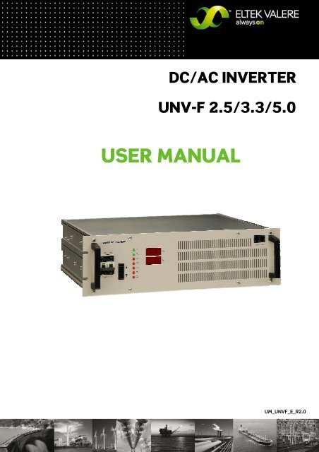
DC/AC INVERTER<br />
UNV-F 2.5/3.3/5.0<br />
<strong>USER</strong> <strong>MANUAL</strong><br />
UM_UNVF_E_R2.0
DC/AC Inverter<br />
UNV-F<br />
User Manual<br />
Page 2 (28)<br />
Notes to this manual<br />
ATTENTION! Read this manual very carefully before installing and commissioning the specified module.<br />
This manual is a part of the delivered module. Familiarity with the contents of this manual is required for<br />
installing and operating the specified module.<br />
The rules for prevention of accidents for the specific country and the general safety rules in accordance with<br />
IEC 364 must be observed.<br />
The function description in this manual corresponds to the date of publishing.<br />
Technical changes and changes in form and content can be made at any time by the manufacturer without<br />
notice. There are no obligations to update the manual continually.<br />
The module is manufactured in accordance with applicable DIN and VDE standards such as VDE 0106 (part 100)<br />
and VDE 0100 (part 410). The CE marking on the module confirms compliance with EU standards 2006-95-EG<br />
(low voltage) and 2004-108-EG (electromagnetic compatibility) if the installation and operation instructions are<br />
followed.<br />
Supplier:<br />
ELTEK VALERE DEUTSCHLAND GmbH<br />
GB Industrial<br />
Schillerstraße 16<br />
D-32052 Herford<br />
+ 49 (0) 5221 1708-210<br />
FAX + 49 (0) 5221 1708-222<br />
Email Info.industrial@eltekvalere.com<br />
Internet http://www.eltekvalere.com<br />
2009. ELTEK VALERE DEUTSCHLAND GmbH. All rights reserved.<br />
©2009. ELTEK VALERE DEUTSCHLAND GmbH. UM_UNVF_ E_R2.0
DC/AC Inverter<br />
UNV-F<br />
User Manual<br />
Page 3 (28)<br />
The current revision status of this user manual is the following:<br />
Revision: 2.0<br />
Date: 2009-07-31<br />
Revision Description of change Writer Date<br />
01-03 Minor text modifications RTH<br />
04 ELTEK VALERE INDUSTRIAL layout inserted RTH 2008-01-29<br />
1.0<br />
New revision status numbering (X.X) introduced, section “Error<br />
indication on the displays” inserted.<br />
RTH 2009-04-20<br />
2.0 Minor reworking at sections 3.4, 4.2, 7. RTH 2009-07-31<br />
©2009. ELTEK VALERE DEUTSCHLAND GmbH. UM_UNVF_ E_R2.0
DC/AC Inverter<br />
UNV-F<br />
User Manual<br />
Page 4 (28)<br />
Table of Contents<br />
1A. SAFETY INSTRUCTIONS ........................................................................................................................................5<br />
1B. ELECTRIC WASTE DISPOSAL ................................................................................................................................5<br />
2. GENERAL INFORMATION..........................................................................................................................................6<br />
2.1 TYPICAL APPLICATIONS ...........................................................................................................................................6<br />
3. TYPE RANGE/EQUIPMENT ......................................................................................................................................7<br />
3.1 MOUNTING ACCESSORIES.........................................................................................................................................7<br />
3.2 FRONT VIEW/OPERATION ELEMENTS.......................................................................................................................8<br />
3.3 ELECTRICAL CONNECTORS.......................................................................................................................................9<br />
3.3.1 Electrical Connector X1 for UNV-F 2.5 – 3.3kVA, UNV60-5.0F and UNV110-5.0F ...................9<br />
3.3.2 Electrical Connector X1 for UNV48-5.0F (HAN K 6/6).................................................................. 10<br />
3.3.3 CAN-Bus connectors CAN1 & CAN2.................................................................................................. 11<br />
3.4 COOLING/AIR FLOW DIRECTION ............................................................................................................................ 11<br />
3.5 COMMUNICATION INTERFACE ................................................................................................................................12<br />
4. HANDLING................................................................................................................................................................ 12<br />
4.1 STORAGE.............................................................................................................................................................. 12<br />
4.2 COMMISSIONING ................................................................................................................................................... 12<br />
4.2.1 Single inverter ........................................................................................................................................ 13<br />
4.2.2 Operation in parallel .............................................................................................................................. 13<br />
4.2.3 CAN-Bus Addressing............................................................................................................................. 13<br />
4.3 LED INDICATIONS ................................................................................................................................................. 14<br />
4.4 INTERNAL MONITORING......................................................................................................................................... 15<br />
4.5 ADJUSTMENT OF THE STANDARD AND THRESHOLD VALUES................................................................................... 16<br />
4.5.1 Diagram “Standard display during operation/display of input and output parameters”..... 17<br />
4.5.2 Diagram “Adjustment mode”............................................................................................................... 19<br />
4.5.3 Table “Adjustable Parameters” .......................................................................................................... 21<br />
5. MAINTENANCE........................................................................................................................................................ 22<br />
6. TROUBLE SHOOTING ............................................................................................................................................. 22<br />
6.1 FAILURE TABLE..................................................................................................................................................... 22<br />
6.2 ERROR INDICATION ON THE DISPLAYS .................................................................................................................... 23<br />
7. TECHNICAL SPECIFICATIONS............................................................................................................................... 25<br />
7.1 DIMENSIONAL DRAWINGS ...................................................................................................................................... 27<br />
©2009. ELTEK VALERE DEUTSCHLAND GmbH. UM_UNVF_ E_R2.0
DC/AC Inverter<br />
UNV-F<br />
User Manual<br />
Page 5 (28)<br />
1A. Safety Instructions<br />
Warning!<br />
Because several components of operating electrical modules are charged by dangerous voltage, the<br />
improper handling of electrical modules may be the cause of accidents involving electrocution,<br />
injury, or material damages.<br />
Operation and maintenance of electrical modules must be performed by qualified skilled<br />
personnel such as electricians in accordance with EN 50110-1 or IEC 60950.<br />
Install the module only in areas with limited access to unskilled personnel.<br />
Before starting work, the electrical module must be disconnected from mains. Make sure<br />
that the module is earthed.<br />
Do not touch connector pins as they can be charged with dangerous voltage up to 30<br />
seconds after disconnection.<br />
Only spare parts approved by the manufacturer must be used.<br />
1B. Electric Waste Disposal<br />
Separate collection is the precondition to ensure specific treatment and recycling of waste electrical and<br />
electronic equipment and is necessary to achieve the chosen level of protection of human health and the<br />
environment.<br />
In the case of waste disposal of your discarded equipment we recommend to contact a waste management<br />
company.<br />
©2009. ELTEK VALERE DEUTSCHLAND GmbH. UM_UNVF_ E_R2.0
DC/AC Inverter<br />
UNV-F<br />
User Manual<br />
Page 6 (28)<br />
2. General Information<br />
Inverters of the series UNV-F convert input side DC voltage to a stable sinusoidal output voltage.<br />
The inverters are available for delivery with an output power of 2.5, 3.3 and 5.0 kVA per module.<br />
Several units can be switched in parallel operation to increase the system output power.<br />
The UNV-F is a hot-pluggable module with rear side connectors. Only the communication wire (CAN-Bus) is<br />
connected at the front. The inverters are controlled and monitored by an internal microprocessor. Due to the<br />
outstanding switching principle the units have very low losses and therefore very compact dimensions, low<br />
weight and a very high power density.<br />
All main functional parameters are adjustable with front side operating keys and are indicated with digital<br />
displays.<br />
To increase the reliability the UNV-F inverter is designed to operate together with a static transfer switch of<br />
series UNB. The static transfer switch monitors the connected bypass mains and synchronizes the inverter<br />
output with mains frequency. In inverter priority mode the UNB transfers the load supply to bypass mains in<br />
case of inverter faults, high overload or battery low voltage. The transfer is nearly without voltage interruption<br />
(
DC/AC Inverter<br />
UNV-F<br />
User Manual<br />
Page 7 (28)<br />
3. Type Range/Equipment<br />
Type<br />
designation<br />
Material code Nominal<br />
Inputvoltage<br />
(VDC)<br />
Nominal<br />
Input<br />
current<br />
(ADC)<br />
Nominal<br />
Outputvoltage<br />
(VAC)<br />
Output<br />
frequency<br />
(Hz)<br />
Output-<br />
power<br />
(VA<br />
@ cosφ =0.8)<br />
Dimensions<br />
W/H/D (mm)<br />
UNV48-2.5F 500-025-511.00 48 47.3 230 50/60 2500 483/133/360<br />
UNV60-2.5F 500-025-611.00 60 37.9 230 50/60 2500 483/133/360<br />
UNV110-2.5F 500-025-711.00 108 20.4 230 50/60 2500 483/133/360<br />
UNV48-3.3F 500-033-511.00 48 62.5 230 50/60 3300 483/133/360<br />
UNV60-3.3F 500-033-611.00 60 50.0 230 50/60 3300 483/133/360<br />
UNV110-3.3F 500-033-711.00 108 26.7 230 50/60 3300 483/133/360<br />
UNV48-5.0F 500-050-511.00 48 94.7 230 50/60 5000 483/133/440<br />
UNV60-5.0F 500-050-611.00 60 74.9 230 50/60 5000 483/133/440<br />
UNV110-5.0F 500-050-711.00 108 39.9 230 50/60 5000 483/133/440<br />
For more specific data, see section 7.<br />
3.1 Mounting accessories<br />
Mounting set for 19’’ cabinet (not for UNV48-5.0F): Mat. code 880-MEC-MKT.01<br />
Mounting set for 19’’ cabinet (for UNV48-5.0F): Mat. code 880-MEC-MKT.02<br />
The mounting set is necessary to fit the UNV module in a 19’’ compatible cabinet (see section 4.2<br />
“commissioning”).<br />
©2009. ELTEK VALERE DEUTSCHLAND GmbH. UM_UNVF_ E_R2.0
DC/AC Inverter<br />
UNV-F<br />
User Manual<br />
Page 8 (28)<br />
3.2 Front View/Operation Elements<br />
Digital displays Two CAN-Bus connectors<br />
LED indicators Ventilation grid<br />
UP/DOWN keys<br />
ON/OFF switch<br />
(Input/output fuse)<br />
All operating elements are arranged at the front side of the module. The UNV-F, 2.5 and 3.3kVA are fitted with a<br />
combined input and output MCB which is used as ON/OFF switch, whereas the 5.0kVA version is fitted with a<br />
mechanical switch.<br />
As shown with the front view the unit is equipped with seven LED indications:<br />
Switch symbol (Operation)<br />
Vo (Output voltage ok)<br />
Vi> (Input overvoltage)<br />
Vi< (Input undervoltage)<br />
Io> (Overload)<br />
T> (Overtemperature)<br />
Bell symbol (General alarm)<br />
Two digital displays indicate the output voltage and output current values.<br />
Detailed information concerning signalling and monitoring are described in the following sections.<br />
©2009. ELTEK VALERE DEUTSCHLAND GmbH. UM_UNVF_ E_R2.0
DC/AC Inverter<br />
UNV-F<br />
User Manual<br />
Page 9 (28)<br />
3.3 Electrical Connectors<br />
3.3.1 Electrical Connector X1 for UNV-F 2.5 – 3.3kVA, UNV60-5.0F and UNV110-5.0F<br />
X1 (HAN-K4/8) socket outlet (DC input voltage / AC output voltage and signalling):<br />
X1/Pin Designation<br />
1 DC input, plus pole<br />
2 AC output, neutral conductor<br />
3 DC input, minus pole<br />
4 AC output, phase L1<br />
5 ---<br />
6 SYNC-GND (synchronous bus ground)<br />
7 SYNC-SIG* (synchronous bus 50Hz-signal)<br />
8 SYNC-STAT** (synchronous bus state lines)<br />
9 ---<br />
10 Collective failure COM***<br />
11 Collective failure OK (normally open=NO)<br />
12 Collective failure error (normally closed=NC)<br />
The maximum allowed load for the relay contacts is:<br />
@ V= 110V / I< 0.45ADC<br />
@ V 60VDC / I< 1ADC<br />
*In parallel operation the contacts SYNC – GND and SYNC – SIG of each inverter have to be wired.<br />
**In operation with an UNB it is necessary to interconnect the synchronization bus (contacts SYNC – GND, SYNC<br />
– SIG and SYNC – STAT) between the inverter(s) and the UNB.<br />
***Potential free relay contact with safe electrical separation to the AC and DC side; in case of failure COM and<br />
NC are closed.<br />
©2009. ELTEK VALERE DEUTSCHLAND GmbH. UM_UNVF_ E_R2.0
DC/AC Inverter<br />
UNV-F<br />
User Manual<br />
Page 10 (28)<br />
3.3.2 Electrical Connector X1 for UNV48-5.0F (HAN K 6/6)<br />
X1/Pin Designation<br />
1 DC input, Plus<br />
2 ---<br />
3 ---<br />
4 AC output, phase L1<br />
5 DC input, Minus<br />
PE PE<br />
6 AC output, neutral conductor<br />
11 Collective failure COM*<br />
12 SYNC-GND (synchronous bus ground)<br />
13 Collective failure OK (normally open=NO)<br />
14 Collective failure error (normally closed=NC)<br />
15 SYNC-SIG** (synchronous bus 50Hz-signal)<br />
16 SYNC-STAT*** (synchronous bus state lines)<br />
*Potential free relay contact with safe electrical separation to the AC and DC side; in case of failure COM and NC<br />
are closed.<br />
**In parallel operation the contacts SYNC – GND and SYNC – SIG of each inverter have to be wired.<br />
*** In operation with an UNB it is necessary to interconnect the synchronization bus (contacts SYNC – GND,<br />
SYNC – SIG and SYNC – STAT) between the inverter(s) and the UNB.<br />
©2009. ELTEK VALERE DEUTSCHLAND GmbH. UM_UNVF_ E_R2.0
DC/AC Inverter<br />
UNV-F<br />
User Manual<br />
Page 11 (28)<br />
3.3.3 CAN-Bus connectors CAN1 & CAN2<br />
The UNV-F is fitted with two CAN-Bus connectors at the front side (socket outlet RJ11, 6-pole):<br />
CAN<br />
1 6<br />
CAN-Bus connector (socket)<br />
Pin Signals CAN1 Signals CAN2 Designation<br />
1 CAN_V+ DC-Supply +8...15V<br />
2 CAN_V+ DC-Supply +8...15V<br />
3 CAN_H Signal (high)<br />
4 CAN_L Signal (low)<br />
5 CAN_V- DC-Supply Ground<br />
6 CAN_V- DC-Supply Ground<br />
3.4 Cooling/Air Flow Direction<br />
The unit is cooled with an internal fan. The airflow is from the front to rear side. The fan is monitored and speed<br />
controlled dependent on module temperature. To provide sufficient air flow, a minimum space (see item A in the<br />
following figure) of 50 mm is required between the unit and the rear cabinet wall as well as an unobstructed<br />
supply of air to the front of the module.<br />
Please note:<br />
The ambient temperature should not exceed a maximum of 45°C.<br />
If the UNV-F module is integrated into a cabinet, the ambient temperature should not exceed a<br />
maximum of 40°C.<br />
©2009. ELTEK VALERE DEUTSCHLAND GmbH. UM_UNVF_ E_R2.0
DC/AC Inverter<br />
UNV-F<br />
User Manual<br />
Page 12 (28)<br />
3.5 Communication Interface<br />
The inverter UNV-F is equipped with a serial data interface according to CAN (= Controller Area Network) –<br />
specification. Via CAN-Bus, several devices in a system or parallel connection can be controlled and monitored<br />
by a central unit which is integrated into the static transfer switch unit UNB.<br />
Following parameters of a specific inverter unit can be controlled or monitored:<br />
Remote ON/OFF<br />
Inverter status (OK/failure)<br />
Input voltage (measurement value)<br />
Input current (measurement value)<br />
The CAN-Bus connectors are located at the front panel. The wiring to the central unit should be as short as<br />
possible. The cable length must not exceed 30m.<br />
4. Handling<br />
4.1 Storage<br />
The devices must be stored in a dry, dust free environment with a storage temperature according to specific<br />
data (please see section 7).<br />
4.2 Commissioning<br />
Note: Before commissioning the module, make sure that the input voltage corresponds to the input voltage<br />
range of the unit as specified on the type plate.<br />
If the inverter is to be mounted in a 19’’ compatible cabinet, a mounting set is necessary (see picture below).<br />
After unpacking the unit put it upon the rails and slide in the unit carefully over the rails until the module<br />
connector gets in touch with the backplane connector. Increase the pressure a little bit until the unit fits in<br />
completely. Please avoid too much pressure. If the unit does not fit in please start again with the complete<br />
slide-in process.<br />
Mount the unit with 4 screws (M4x12).<br />
Mounting set for UNV-F<br />
(shown with an UNV-F unit).<br />
©2009. ELTEK VALERE DEUTSCHLAND GmbH. UM_UNVF_ E_R2.0
DC/AC Inverter<br />
UNV-F<br />
User Manual<br />
Page 13 (28)<br />
For the electrical connection of DC input and AC output the backside panel connector is to be used. The DC<br />
input is protected against wrong polarity (unit does not switch on). The UNV-F with output power of 2.5 and<br />
3.3kVA are fitted with an output side MCB fusing at the front panel combined with an input side MCB, whereas<br />
the 5kVA version is fitted with a mechanical switch. That means that the 5kVA version must be fused with<br />
external fuses.<br />
If the UNV-F works in combination with a static bypass switch (UNB) the CAN-Bus cable must be connected to<br />
one of the CAN-Bus connectors at the front of the unit.<br />
Please check the load power before the module is connected.<br />
A permanent overload is not allowed and decreases the inverters lifetime. Especially the inrush currents of<br />
loads have to be observed (e.g. the inrush current of an usual computer monitor can be more than<br />
50A).<br />
The connection of a non-fused protective earth conductor is required. The electrical connections have to be<br />
done according to the pin list in section 3.3. Please use wires acc. to VDE 0100 or equal standard. To decrease<br />
voltage losses on cables the usage of bigger sizes of wire as specified is recommended. For instance, a high<br />
voltage loss on battery wires can decrease the backup time.<br />
The following commissioning rules should be observed:<br />
4.2.1 Single inverter<br />
check the system wiring (polarity of DC- supply line)<br />
check that the inverter is switched off<br />
connect DC input with open DC busbar fuses<br />
connect AC loads<br />
close the DC busbar fuses<br />
switch on the unit by front side MCB actuation<br />
switch on the load<br />
4.2.2 Operation in parallel<br />
Before commissioning paralleled units make sure that the output voltage and frequency matches.<br />
check the system wiring (polarity of DC- supply line, synchronous bus)<br />
check that the inverters are switched off<br />
connect DC input with open DC busbar fuses<br />
check the wiring between inverters (synchronization wires)<br />
connect AC loads<br />
close DC busbar fuses<br />
switch on the units by front side MCB actuation<br />
switch on the load<br />
Note: The unit which transmits the synchonization signal to the synchronization bus at first will be the master.<br />
If this master unit is disturbed or switched off, another unit overtakes the master function. In systems with a<br />
static transfer switch (UNB) the inverters are synchronized by the UNB unit.<br />
The inverter output relay switches the inverter output to the AC busbar if the internal voltage is okay and the<br />
output voltage is within the correct range. In this way defective modules switch off themselves and are<br />
disconnected from the AC bus automatically.<br />
4.2.3 CAN-Bus Addressing<br />
If paralleled inverters work in combination with a static transfer switch (UNB), the respective inverters within<br />
the system must be addressed for a clear identification via the CAN-Bus. The specific address per inverter<br />
(module) must be allocated with the adjustment keys in the “basic menu PM1” (please see the section 4.5. and<br />
the following).<br />
The standard address (factory set) of the inverter is “001”.<br />
©2009. ELTEK VALERE DEUTSCHLAND GmbH. UM_UNVF_ E_R2.0
DC/AC Inverter<br />
UNV-F<br />
User Manual<br />
Page 14 (28)<br />
4.3 LED Indications<br />
The following functions are indicated with front side LEDs:<br />
LED Colour Meaning<br />
green Inverter is switched on and operates<br />
green Inverter output voltage okay*<br />
red Input voltage high*<br />
red Input voltage low*<br />
red Output current to high; short circuit or overload at the output<br />
red<br />
red<br />
* Adjustment of the threshold values, please see section 4.5<br />
**Only with the service menu PM2.<br />
1.) Lights continuously: Overheating of the inverter by overload.<br />
2.) Blinking: Malfunction of the cooling fan<br />
Collective failure; the delay time of the relay alarm is adjustable**; relay<br />
contact at X1; all single failures are included.<br />
©2009. ELTEK VALERE DEUTSCHLAND GmbH. UM_UNVF_ E_R2.0
DC/AC Inverter<br />
UNV-F<br />
User Manual<br />
Page 15 (28)<br />
4.4 Internal Monitoring<br />
Monitored values Criteria Function<br />
Vi: The device automatically switches off<br />
without delay time (protection against<br />
overvoltage). It switches on if the input<br />
voltage is lower than the adjusted switch off<br />
threshold*.<br />
AC output voltage<br />
AC output current<br />
Overheating;<br />
Cooling fan<br />
function<br />
Output voltage higher than adjusted<br />
operating threshold*<br />
Output voltage lower than adjusted<br />
operating threshold*<br />
>130% Inom<br />
>100% Inom<br />
Internal temperature higher than<br />
adjusted threshold (factory setting)<br />
The device automatically switches off; manual<br />
restart is necessary.<br />
LED “Vo” = OFF; LED “collective failure”= ON<br />
LED “Io>” = ON; After 3 seconds the device<br />
automatically switches off; automatic restart<br />
after 15 seconds (for 3 times).<br />
After 30 seconds follows an automatic<br />
shutoff; manual restart is necessary.<br />
The device automatically switches off with<br />
delay time. It automatically switches on if the<br />
temperature is lower than adjusted switch on<br />
threshold. LED T> is on.<br />
Additionally the fan voltage and current<br />
characteristic is monitored to detect a<br />
defective fan. This is indicated by a blinking<br />
LED T>.<br />
* Adjustment of the threshold values please see section 4.5 //**Only with the service menu PM2.<br />
©2009. ELTEK VALERE DEUTSCHLAND GmbH. UM_UNVF_ E_R2.0
DC/AC Inverter<br />
UNV-F<br />
User Manual<br />
Page 16 (28)<br />
4.5 Adjustment of the standard and threshold values<br />
The adjustment takes place with up/down keys located at the front panel of the inverter while the displays<br />
indicate the actual values.<br />
Front keys Designation Operation<br />
up<br />
down<br />
The inverter offers two adjustment menus:<br />
during menu item selection: change to<br />
previous item (parameter)<br />
during adjustment mode: increase value<br />
during menu item selection: change to next<br />
item (parameter)<br />
during adjustment mode: decrease value<br />
The basic menu PM1 is available for all users.<br />
The service menu PM2 is available for service personnel only. PM2 is code protected to guard against illegal<br />
parameter changes.<br />
In the operation mode the top display indicates the output voltage and the bottom display indicates the output<br />
current. With pressing the key UP () or DOWN () you are able to switch back and forth between the input and<br />
output parameters according to the diagram “Standard display during operation/display of input and output<br />
parameters” (see section 4.5.1)<br />
For the adjustment of parameters in the basic menu PM1 the following procedure has to be carried out (see<br />
also section 4.5.2, diagram “Adjustment mode”):<br />
1. press both keys UP/DOWN () together for short time; the inverter changes to the adjustment mode<br />
2. press the key UP () or DOWN () to change the parameter (see also diagram “Adjustment mode”)<br />
3. press both keys UP/DOWN () together for short time; the inverter changes to the value change mode<br />
4. press the key UP () or DOWN () to change the adjustment value<br />
5. press both keys UP/DOWN () together for short time; the inverter changes back to adjustment<br />
mode (the upper display shows a horizontal line / the changed value is saved at this moment)<br />
6. press both keys UP/DOWN () for approximately three seconds to change back to the operation mode<br />
(For the table of the adjustable parameters in the basic menu PM1, please see section 4.5.3)<br />
©2009. ELTEK VALERE DEUTSCHLAND GmbH. UM_UNVF_ E_R2.0
DC/AC Inverter<br />
UNV-F<br />
User Manual<br />
Page 17 (28)<br />
4.5.1 Diagram “Standard display during operation/display of input and output parameters”<br />
The continuation of the diagram is on the next page!<br />
©2009. ELTEK VALERE DEUTSCHLAND GmbH. UM_UNVF_ E_R2.0
DC/AC Inverter<br />
UNV-F<br />
User Manual<br />
Page 18 (28)<br />
Continuation of the previous page:<br />
By pressing both keys short-time at the position “” (Hardware reset) the device switches off and restarts.<br />
©2009. ELTEK VALERE DEUTSCHLAND GmbH. UM_UNVF_ E_R2.0
DC/AC Inverter<br />
UNV-F<br />
User Manual<br />
Page 19 (28)<br />
4.5.2 Diagram “Adjustment mode”<br />
For switching to the adjustment mode shortly press both keys together at any position within the<br />
display of input and output parameters (except for the position “hardware reset”).<br />
©2009. ELTEK VALERE DEUTSCHLAND GmbH. UM_UNVF_ E_R2.0
DC/AC Inverter<br />
UNV-F<br />
User Manual<br />
Page 20 (28)<br />
You can leave the adjustment mode by pressing both keys for approximately three seconds.<br />
©2009. ELTEK VALERE DEUTSCHLAND GmbH. UM_UNVF_ E_R2.0
DC/AC Inverter<br />
UNV-F<br />
User Manual<br />
Page 21 (28)<br />
4.5.3 Table “Adjustable Parameters”<br />
Following table shows the standard values (factory set), adjustment ranges and steps:<br />
Display1 Designation Factory setting Range Step<br />
<br />
nominal value of output<br />
voltage Uo<br />
230 [VAC] 200...255 0,25 [V] *<br />
monitoring threshold of 207 [VAC]<br />
output voltage low Uo<<br />
180...230 1,0 [V]<br />
Monitoring threshold of 253 [VAC] 230...270 1,0 [V]<br />
output voltage high<br />
Uo><br />
<br />
switch off threshold<br />
input voltage high Ui><br />
48/60V: 75 [VDC]<br />
108V: 130<br />
0...80<br />
0...135<br />
0,1 [V]<br />
0,25 [V]*<br />
switch off threshold 48V: 41 [VDC] 41...80 0,1 [V]<br />
input voltage low Ui< 60V: 51 [VDC]<br />
108V: 92 [VDC]<br />
41...80<br />
90...110<br />
0,1 [V]<br />
0,25 [V]*<br />
switch on again 48V: 45 [VDC] 41...80 0,1 [V]<br />
<br />
threshold input voltage<br />
low Ui<<br />
60V: 56 [VDC]<br />
108V: 96 [VDC]<br />
41...80<br />
90...110<br />
0,1 [V]<br />
0,25 [V]*<br />
<br />
CAN Address 001 1<br />
*When adjusting the threshold values with up/down keys, the moving dot shows the actual value according to<br />
the example (this applies only to the 0.25 steps):<br />
Example:<br />
corresponds to 230.0<br />
corresponds to 230.25<br />
corresponds to 230.5<br />
corresponds to 230.75<br />
With each click at the UP/Down keys the dot moves. After four times clicking (4/4), the voltage value is<br />
increased (or decreased) for 1V.<br />
©2009. ELTEK VALERE DEUTSCHLAND GmbH. UM_UNVF_ E_R2.0
DC/AC Inverter<br />
UNV-F<br />
User Manual<br />
Page 22 (28)<br />
5. Maintenance<br />
In general, the inverter is maintenance-free.<br />
A yearly inspection with following checks is recommended:<br />
Correct fan operation<br />
Mechanical inspection<br />
Removal of dust and dirt, especially on radiator surfaces<br />
Check for internal dust or humidity<br />
Attention! Dust combined with dew or water may influence the internal electronic circuits. Dust inside the unit<br />
can be blown out with dry compressed air.<br />
The intervals between this checks depend on ambient conditions of the installed module.<br />
6. Trouble Shooting<br />
6.1 Failure Table<br />
Symptom Possible reason Corrective action<br />
No output voltage DC input voltage ok?<br />
main switch (MCB) on?<br />
green LED „Operation“ on?<br />
incorrect polarity at the input?<br />
DC input fuse (at DC busbar) ok?<br />
signalling LED Vi> or Vi< on ?<br />
Deviation of output<br />
voltage<br />
short circuit or overload at the output?<br />
output fuse ok?<br />
Unit switched off due to overheating<br />
(LED T> on)?<br />
overload at the output?<br />
big inrush current of load?<br />
distortions by load steps or current<br />
peaks?<br />
adjustment of voltage value Vo not<br />
correct?<br />
→ check<br />
→ check<br />
→ check<br />
→ check<br />
→ check<br />
→ check the adjustment values of Vi<br />
(see item 4.5.2)<br />
→ check/reduce load<br />
→ check<br />
→ search after the cause of the<br />
overheating<br />
→ check/reduce load<br />
→ check<br />
→ check<br />
→ check /adjust Vo to the correct<br />
value (see item 4.5.2)<br />
If the unit still does not work even though all checks are done, please contact your sales agent or the service<br />
department of Eltek Valere Deutschland.<br />
©2009. ELTEK VALERE DEUTSCHLAND GmbH. UM_UNVF_ E_R2.0
DC/AC Inverter<br />
UNV-F<br />
User Manual<br />
Page 23 (28)<br />
6.2 Error indication on the displays<br />
Switch-off (shutdown of the module) caused by error is indicated on the displays.<br />
Example:<br />
<br />
<br />
Upper display:<br />
SHd = Shutdown<br />
Lower display:<br />
Error number (example „129“)<br />
Possible single error numbers are listed in the table below:<br />
Error number (decimal number) Meaning<br />
1 Io> or Vi><br />
2 Vi< or fan error<br />
4 Vo not ok (e.g. restart error)<br />
8 T> or input DC/DC converter not ok<br />
16 Internal error<br />
32 Switch off via CAN-Bus (e.g. by static bypass switch UNB)<br />
64 Vo><br />
128 Vo<<br />
If more than one error appeared, the result (addition of the single error numbers) is shown at the lower display.<br />
The example above (error number „129“) is the result of error number „1“ plus error number „128“.<br />
For error numbers which include two possibilities (error number „1“, „2“ and „8“) please note the LED which<br />
additionally is “ON” for an identification of the error.<br />
A further example to clarify:<br />
<br />
<br />
Upper display:<br />
SHd = Shutdown<br />
Lower display:<br />
Error number (example „138“)<br />
Error number „138“ is the result of „128“ + „8“ + „2“.<br />
„2“ means “input under voltage” (LED „Vi“ is blinking).<br />
„8“ means “over temperature” (LED „T>“ is ON) or “input DC/DC converter is not ok”.<br />
„128“ means „output under voltage”. Because the module has switched OFF there is no output voltage. Due to<br />
this, the error „output under voltage“ also is included.<br />
©2009. ELTEK VALERE DEUTSCHLAND GmbH. UM_UNVF_ E_R2.0
DC/AC Inverter<br />
UNV-F<br />
User Manual<br />
Page 24 (28)<br />
The following display indications are exceptions:<br />
At shutdown due to short circuit or overload the displays indicate the following:<br />
<br />
<br />
Upper display:<br />
SHd = Shutdown<br />
Lower display:<br />
ovL = short circuit/overload<br />
An intended shutdown via CAN-Bus by static bypass switch UNB is indicated as follows:<br />
<br />
<br />
Upper display:<br />
OFF (shutdown)<br />
Lower display:<br />
CAn (via CAN-Bus)<br />
©2009. ELTEK VALERE DEUTSCHLAND GmbH. UM_UNVF_ E_R2.0
DC/AC Inverter<br />
UNV-F<br />
User Manual<br />
Page 25 (28)<br />
7. Technical Specifications<br />
Type range UNV-2.5F UNV-3.3F UNV-5.0F<br />
Article code See section 3, table “Type range”<br />
DC Input<br />
Nominal input voltage See section 3, table “Type range”<br />
Input voltage tolerance<br />
range<br />
+20/-15% <br />
Nominal input current See section 3, table “Type range”<br />
Inrush current ≤ nominal current <br />
Overall efficiency ≥87% <br />
Internal input fusing MCB 1-pole No, external<br />
AC Output<br />
Nominal output voltage 230VAC ± 0,5% (±5% at parallel operation), sinusoidal<br />
Nominal output current 10.9AAC 14.35AAC 21.7AAC<br />
Nominal output power See section 3, table “Type range”<br />
Overload capability 130% for 10 seconds <br />
Output frequency 50 or 60Hz<br />
programmable<br />
<br />
Synchronisation range 45- 65Hz <br />
Accuracy ±0.5% static <br />
Recovery time , Vi
DC/AC Inverter<br />
UNV-F<br />
User Manual<br />
Page 26 (28)<br />
Audible noise < 45dB (A) <br />
Mechanical<br />
Construction 19’’- compatible rack, full width, rear side connectors<br />
Electrical connectors Input/output and signals : HAN K 4/8 at the rear side;<br />
CAN 1 + 2 at the front side<br />
Cooling Speed-controlled fan with over temperature monitoring<br />
Type of enclosure IP20 (front panel)<br />
Input/output and signals<br />
: HAN K 4/8 (HAN K 6/6:<br />
UNV48-5.0F) at the rear<br />
side;<br />
CAN 1 + 2 at the front<br />
side<br />
Dimensions (W/H/D)<br />
[mm]<br />
483/133/360 483/133/360 483/133/440<br />
Minimum installation<br />
depth [mm]<br />
440 ex. 19’’ frame 440 ex. 19’’ frame 550 ex. 19’’ frame<br />
Weight approx. 22 kg approx. 27 kg approx. 38 kg<br />
Surfaces Front panel: powder coating RAL 7035; neutral, black print RAL 9005;<br />
constructive parts: anodized metal<br />
Compliances<br />
CE conformity yes <br />
Compliance to safety<br />
standards<br />
Compliance to EMC<br />
standards<br />
EN60950-1; VDE0100 T410; VDE0110; EN50178; EN60146<br />
EN55011/22 class “B“; EN61000-4 T2-5<br />
©2009. ELTEK VALERE DEUTSCHLAND GmbH. UM_UNVF_ E_R2.0
DC/AC Inverter<br />
UNV-F<br />
User Manual<br />
Page 27 (28)<br />
7.1 Dimensional drawings<br />
UNV-2.5F/UNV-3.3F:<br />
UNV-5.0F:<br />
©2009. ELTEK VALERE DEUTSCHLAND GmbH. UM_UNVF_ E_R2.0
Supplier:<br />
ELTEK VALERE DEUTSCHLAND GmbH<br />
GB Industrial<br />
Schillerstraße 16<br />
D-32052 Herford<br />
+ 49 (0) 5221 1708-210<br />
FAX + 49 (0) 5221 1708-222<br />
Email Info.industrial@eltekvalere.com<br />
Internet http://www.eltekvalere.com<br />
2009. ELTEK VALERE DEUTSCHLAND GmbH. All rights reserved.