ICTCP: Incast Congestion Control for TCP in Data Center ... - Sigcomm
ICTCP: Incast Congestion Control for TCP in Data Center ... - Sigcomm
ICTCP: Incast Congestion Control for TCP in Data Center ... - Sigcomm

You also want an ePaper? Increase the reach of your titles
YUMPU automatically turns print PDFs into web optimized ePapers that Google loves.
outers support (such as ECN) and modifications at<br />
both <strong>TCP</strong> sender and receiver sides.<br />
Our idea is to per<strong>for</strong>m <strong>in</strong>cast congestion avoidance at<br />
receiver side by prevent<strong>in</strong>g <strong>in</strong>cast congestion. Receiver<br />
side is a natural choice s<strong>in</strong>ce it knows the throughput<br />
of all <strong>TCP</strong> connections and the available bandwidth.<br />
The receiver side can adjust the receive w<strong>in</strong>dow size of<br />
each <strong>TCP</strong> connection, so the aggregate burst<strong>in</strong>ess of all<br />
the synchronized senders are under control. We call our<br />
design <strong>IC<strong>TCP</strong></strong> (<strong>Incast</strong> congestion <strong>Control</strong> <strong>for</strong> <strong>TCP</strong>).<br />
But well controll<strong>in</strong>g the receive w<strong>in</strong>dow is challeng<strong>in</strong>g:<br />
The receive w<strong>in</strong>dow should be small enough to avoid<br />
<strong>in</strong>cast congestion, but also large enough <strong>for</strong> good per<strong>for</strong>mance<br />
and other non-<strong>in</strong>cast cases. A well per<strong>for</strong>med<br />
throttl<strong>in</strong>g rate <strong>for</strong> one <strong>in</strong>cast scenario may not fit well<br />
<strong>for</strong> other scenarios due to the dynamics of the number<br />
of connections, traffic volumes, network conditions, etc.<br />
This paper addresses the above challenges by a systematically<br />
designed <strong>IC<strong>TCP</strong></strong>. We first per<strong>for</strong>m congestion<br />
avoidance at system level. We then use per-flow<br />
state to f<strong>in</strong>e-gra<strong>in</strong>ed tune the receive w<strong>in</strong>dow of each<br />
connection at the receiver side. The technical novelties<br />
of this work are as follows: 1) To per<strong>for</strong>m congestion<br />
control at receiver side, we use the available bandwidth<br />
on the network <strong>in</strong>terface as a quota to coord<strong>in</strong>ate the<br />
receive w<strong>in</strong>dow <strong>in</strong>crease of all <strong>in</strong>com<strong>in</strong>g connections. 2)<br />
Our per flow congestion control is per<strong>for</strong>med <strong>in</strong>dependently<br />
<strong>in</strong> slotted time of RTT (Round Trip Time) on<br />
each connection, which is also the control latency <strong>in</strong><br />
its feedback loop. 3) Our receive w<strong>in</strong>dow adjustment<br />
is based on the ratio of difference of measured and expected<br />
throughput over expected one. This is to estimate<br />
the throughput requirement from sender side and<br />
adapt receiver w<strong>in</strong>dow correspond<strong>in</strong>gly. Besides, we<br />
f<strong>in</strong>d live RTT is necessary <strong>for</strong> throughput estimation<br />
as we observe that <strong>TCP</strong> RTT <strong>in</strong> high-bandwidth lowlatency<br />
network does <strong>in</strong>crease with throughput, even if<br />
l<strong>in</strong>k capacity is not reached.<br />
We have developed and implemented <strong>IC<strong>TCP</strong></strong> as a<br />
W<strong>in</strong>dows NDIS (Network Driver Interface Specification)<br />
filter driver. Our implementation naturally support virtual<br />
mach<strong>in</strong>es which are now widely used <strong>in</strong> data center.<br />
In our implementation, <strong>IC<strong>TCP</strong></strong> as a driver locates at hypervisors<br />
below virtual mach<strong>in</strong>es. This choice removes<br />
the difficulty on obta<strong>in</strong><strong>in</strong>g the real available bandwidth<br />
after virtual <strong>in</strong>terfaces’ multiplex<strong>in</strong>g. It also provides<br />
a common waist <strong>for</strong> various <strong>TCP</strong> stacks <strong>in</strong> virtual mach<strong>in</strong>es.<br />
We have built a testbed with 47 Dell servers and<br />
a 48-port Gigabit Ethernet switch. Experiments <strong>in</strong> our<br />
testbed demonstrated the effectiveness of our scheme.<br />
The rest of the paper is organized as follows. Section<br />
2 discusses research background. Section3 describes<br />
the design rationale of <strong>IC<strong>TCP</strong></strong>. Section 4 presents <strong>IC<strong>TCP</strong></strong><br />
algorithms. Section 5 shows the implementation of <strong>IC<strong>TCP</strong></strong><br />
as a W<strong>in</strong>dows driver. Sections 6 presents experimental<br />
<strong>Data</strong> center<br />
Agg. Router<br />
Agg. Switch<br />
ToR<br />
switch<br />
Internet<br />
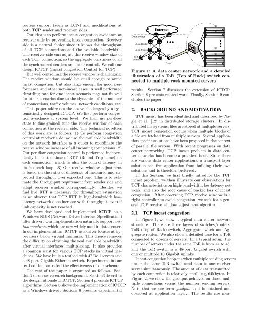
Figure 1: A data center network and a detailed<br />
illustration of a ToR (Top of Rack) switch connected<br />
to multiple rack-mounted servers<br />
results. Section 7 discusses the extension of <strong>IC<strong>TCP</strong></strong>.<br />
Section 8 presents related work. F<strong>in</strong>ally, Section 9 concludes<br />
the paper.<br />
2. BACKGROUND AND MOTIVATION<br />
<strong>TCP</strong> <strong>in</strong>cast has been identified and described by Nagle<br />
et al. [12] <strong>in</strong> distributed storage clusters. In distributed<br />
file systems, files are stored at multiple servers.<br />
<strong>TCP</strong> <strong>in</strong>cast congestion occurs when multiple blocks of<br />
a file are fetched from multiple servers. Several application<br />
specific solutions have been proposed <strong>in</strong> the context<br />
of parallel file system. With recent progresses on data<br />
center network<strong>in</strong>g, <strong>TCP</strong> <strong>in</strong>cast problem <strong>in</strong> data center<br />
networks has become a practical issue. S<strong>in</strong>ce there<br />
are various data center applications, a transport layer<br />
solution can free application from build<strong>in</strong>g their own<br />
solutions and is there<strong>for</strong>e preferred.<br />
In this Section, we first briefly <strong>in</strong>troduce the <strong>TCP</strong><br />
<strong>in</strong>cast problem, we then illustrate our observations <strong>for</strong><br />
<strong>TCP</strong> characteristics on high-bandwidth, low-latency network,<br />
and also the root cause of packet loss of <strong>in</strong>cast<br />
congestion. After observ<strong>in</strong>g <strong>TCP</strong> receive w<strong>in</strong>dow is a<br />
right controller to avoid congestion, we seek <strong>for</strong> a general<br />
<strong>TCP</strong> receive w<strong>in</strong>dow adjustment algorithm.<br />
2.1 <strong>TCP</strong> <strong>in</strong>cast congestion<br />
In Figure 1, we show a typical data center network<br />
structure. There are three layers of switches/routers:<br />
ToR (Top of Rack) switch, Aggregate switch and Aggregate<br />
router. We also show a detailed case <strong>for</strong> a ToR<br />
connected to dozens of servers. In a typical setup, the<br />
number of servers under the same ToR is from 44 to 48,<br />
and the ToR switch is a 48-port Gigabit switch with<br />
one or multiple 10 Gigabit upl<strong>in</strong>ks.<br />
<strong>Incast</strong> congestion happens when multiple send<strong>in</strong>g servers<br />
under the same ToR switch send data to one receiver<br />
server simultaneously. The amount of data transmitted<br />
by each connection is relatively small, e.g, 64kbytes. In<br />
Figure 2, we show the goodput achieved on those multiple<br />
connections versus the number send<strong>in</strong>g servers.<br />
Note that we use term goodput as it is obta<strong>in</strong>ed and<br />
observed at application layer. The results are mea-<br />
1 U<br />
1 U<br />
1 U<br />
1 U<br />
1 U