ICTCP: Incast Congestion Control for TCP in Data Center ... - Sigcomm
ICTCP: Incast Congestion Control for TCP in Data Center ... - Sigcomm
ICTCP: Incast Congestion Control for TCP in Data Center ... - Sigcomm

You also want an ePaper? Increase the reach of your titles
YUMPU automatically turns print PDFs into web optimized ePapers that Google loves.
ABSTRACT<br />
<strong>IC<strong>TCP</strong></strong>: <strong>Incast</strong> <strong>Congestion</strong> <strong>Control</strong> <strong>for</strong> <strong>TCP</strong><br />
<strong>in</strong> <strong>Data</strong> <strong>Center</strong> Networks ∗<br />
Haitao Wu ⋆ , Zhenqian Feng ⋆† , Chuanxiong Guo ⋆ , Yongguang Zhang ⋆<br />
{hwu, v-zhfe, chguo, ygz}@microsoft.com,<br />
⋆ Microsoft Research Asia, Ch<strong>in</strong>a<br />
† School of computer, National University of Defense Technology, Ch<strong>in</strong>a<br />
<strong>TCP</strong> <strong>in</strong>cast congestion happens <strong>in</strong> high-bandwidth and lowlatency<br />
networks, when multiple synchronized servers send<br />
data to a same receiver <strong>in</strong> parallel [15]. For many important<br />
data center applications such as MapReduce[5] and Search,<br />
this many-to-one traffic pattern is common. Hence <strong>TCP</strong> <strong>in</strong>cast<br />
congestion may severely degrade their per<strong>for</strong>mances,<br />
e.g., by <strong>in</strong>creas<strong>in</strong>g response time.<br />
In this paper, we study <strong>TCP</strong> <strong>in</strong>cast <strong>in</strong> detail by focus<strong>in</strong>g<br />
on the relationship among <strong>TCP</strong> throughput, round trip time<br />
(RTT) and receive w<strong>in</strong>dow. Different from the previous approach<br />
to mitigate the impact of <strong>in</strong>cast congestion by a f<strong>in</strong>e<br />
gra<strong>in</strong>ed timeout value, our idea is to design an <strong>IC<strong>TCP</strong></strong> (<strong>Incast</strong><br />
congestion <strong>Control</strong> <strong>for</strong> <strong>TCP</strong>) scheme at the receiver side. In<br />
particular, our method adjusts <strong>TCP</strong> receive w<strong>in</strong>dow proactively<br />
be<strong>for</strong>e packet drops occur. The implementation and<br />
experiments <strong>in</strong> our testbed demonstrate that we achieve almost<br />
zero timeout and high goodput <strong>for</strong> <strong>TCP</strong> <strong>in</strong>cast.<br />
Categories and Subject Descriptors<br />
C.2.1 [Network Architecture and Design]: Network<br />
topology, Packet-switch<strong>in</strong>g networks<br />
General Terms<br />
Algorithms, Design<br />
Keywords<br />
<strong>TCP</strong>, <strong>Incast</strong> congestion, <strong>Data</strong> center networks<br />
1. INTRODUCTION<br />
∗ This work was per<strong>for</strong>med when Zhenqian was an <strong>in</strong>tern at<br />
Microsoft Research Asia.<br />
Permission to make digital or hard copies of all or part of this work <strong>for</strong><br />
personal or classroom use is granted without fee provided that copies are<br />
not made or distributed <strong>for</strong> profit or commercial advantage and that copies<br />
bear this notice and the full citation on the first page. To copy otherwise, to<br />
republish, to post on servers or to redistribute to lists, requires prior specific<br />
permission and/or a fee.<br />
ACM CoNEXT 2010, November 30 – December 3 2010, Philadelphia,<br />
USA.<br />
Copyright 2010 ACM 1-4503-0448-1/10/11 ...$<br />
As the de facto reliable transport layer protocol, <strong>TCP</strong><br />
(Transport <strong>Control</strong> Protocol) has been widely used <strong>in</strong><br />
the Internet and works well. However, recent studies<br />
[13, 15] showed that <strong>TCP</strong> does not work well <strong>for</strong><br />
many-to-one traffic pattern on high-bandwidth, lowlatency<br />
networks, where congestion happens when many<br />
synchronized servers under a same Gigabit Ethernet<br />
switch send data to one receiver <strong>in</strong> parallel. Those connections<br />
are called as barrier synchronized s<strong>in</strong>ce the f<strong>in</strong>al<br />
per<strong>for</strong>mance is determ<strong>in</strong>ed by the slowest <strong>TCP</strong> connection<br />
that suffers timeout due to packet losses. The<br />
per<strong>for</strong>mance collapse of those many-to-one <strong>TCP</strong> connections<br />
is called <strong>TCP</strong> <strong>in</strong>cast congestion.<br />
The traffic and network condition <strong>in</strong> data center networks<br />
create the three preconditions <strong>for</strong> <strong>in</strong>cast congestion<br />
as summarized <strong>in</strong> [15]. First, data center networks<br />
are well structured and layered to achieve high bandwidth<br />
and low latency, and the buffer size of ToR (topof-rack)<br />
Ethernet switches is usually small. Second, recent<br />
measurement study showed that barrier synchronized<br />
many-to-one traffic pattern is common <strong>in</strong> data<br />
center networks [9], ma<strong>in</strong>ly caused by MapReduce [5]<br />
alike applications <strong>in</strong> data center. Third, the transmission<br />
data volume <strong>for</strong> such traffic pattern is usually<br />
small.<br />
The root cause of <strong>TCP</strong> <strong>in</strong>cast collapse is that the<br />
highly bursty traffic of multiple <strong>TCP</strong> connections overflow<br />
the Ethernet switch buffer <strong>in</strong> a short period of time,<br />
caus<strong>in</strong>g <strong>in</strong>tense packet losses and thus <strong>TCP</strong> retransmission<br />
and timeout. Previous solutions, focused on either<br />
reduc<strong>in</strong>g the wait<strong>in</strong>g time <strong>for</strong> packet loss recovery by<br />
faster retransmissions [15], or controll<strong>in</strong>g switch buffer<br />
occupation to avoid overflow by us<strong>in</strong>g ECN and modified<br />
<strong>TCP</strong> at both sender and receiver sides[2].<br />
This paper focuses on avoid<strong>in</strong>g packet losses be<strong>for</strong>e<br />
<strong>in</strong>cast congestion, which is more appeal<strong>in</strong>g than recover<strong>in</strong>g<br />
after loss. Of course, recovery schemes can be<br />
complementary to congestion avoidance. The smaller<br />
change we make to the exist<strong>in</strong>g system, the better. To<br />
this end, a solution that modifies <strong>TCP</strong> receiver only<br />
is preferred than solutions that require switches and
outers support (such as ECN) and modifications at<br />
both <strong>TCP</strong> sender and receiver sides.<br />
Our idea is to per<strong>for</strong>m <strong>in</strong>cast congestion avoidance at<br />
receiver side by prevent<strong>in</strong>g <strong>in</strong>cast congestion. Receiver<br />
side is a natural choice s<strong>in</strong>ce it knows the throughput<br />
of all <strong>TCP</strong> connections and the available bandwidth.<br />
The receiver side can adjust the receive w<strong>in</strong>dow size of<br />
each <strong>TCP</strong> connection, so the aggregate burst<strong>in</strong>ess of all<br />
the synchronized senders are under control. We call our<br />
design <strong>IC<strong>TCP</strong></strong> (<strong>Incast</strong> congestion <strong>Control</strong> <strong>for</strong> <strong>TCP</strong>).<br />
But well controll<strong>in</strong>g the receive w<strong>in</strong>dow is challeng<strong>in</strong>g:<br />
The receive w<strong>in</strong>dow should be small enough to avoid<br />
<strong>in</strong>cast congestion, but also large enough <strong>for</strong> good per<strong>for</strong>mance<br />
and other non-<strong>in</strong>cast cases. A well per<strong>for</strong>med<br />
throttl<strong>in</strong>g rate <strong>for</strong> one <strong>in</strong>cast scenario may not fit well<br />
<strong>for</strong> other scenarios due to the dynamics of the number<br />
of connections, traffic volumes, network conditions, etc.<br />
This paper addresses the above challenges by a systematically<br />
designed <strong>IC<strong>TCP</strong></strong>. We first per<strong>for</strong>m congestion<br />
avoidance at system level. We then use per-flow<br />
state to f<strong>in</strong>e-gra<strong>in</strong>ed tune the receive w<strong>in</strong>dow of each<br />
connection at the receiver side. The technical novelties<br />
of this work are as follows: 1) To per<strong>for</strong>m congestion<br />
control at receiver side, we use the available bandwidth<br />
on the network <strong>in</strong>terface as a quota to coord<strong>in</strong>ate the<br />
receive w<strong>in</strong>dow <strong>in</strong>crease of all <strong>in</strong>com<strong>in</strong>g connections. 2)<br />
Our per flow congestion control is per<strong>for</strong>med <strong>in</strong>dependently<br />
<strong>in</strong> slotted time of RTT (Round Trip Time) on<br />
each connection, which is also the control latency <strong>in</strong><br />
its feedback loop. 3) Our receive w<strong>in</strong>dow adjustment<br />
is based on the ratio of difference of measured and expected<br />
throughput over expected one. This is to estimate<br />
the throughput requirement from sender side and<br />
adapt receiver w<strong>in</strong>dow correspond<strong>in</strong>gly. Besides, we<br />
f<strong>in</strong>d live RTT is necessary <strong>for</strong> throughput estimation<br />
as we observe that <strong>TCP</strong> RTT <strong>in</strong> high-bandwidth lowlatency<br />
network does <strong>in</strong>crease with throughput, even if<br />
l<strong>in</strong>k capacity is not reached.<br />
We have developed and implemented <strong>IC<strong>TCP</strong></strong> as a<br />
W<strong>in</strong>dows NDIS (Network Driver Interface Specification)<br />
filter driver. Our implementation naturally support virtual<br />
mach<strong>in</strong>es which are now widely used <strong>in</strong> data center.<br />
In our implementation, <strong>IC<strong>TCP</strong></strong> as a driver locates at hypervisors<br />
below virtual mach<strong>in</strong>es. This choice removes<br />
the difficulty on obta<strong>in</strong><strong>in</strong>g the real available bandwidth<br />
after virtual <strong>in</strong>terfaces’ multiplex<strong>in</strong>g. It also provides<br />
a common waist <strong>for</strong> various <strong>TCP</strong> stacks <strong>in</strong> virtual mach<strong>in</strong>es.<br />
We have built a testbed with 47 Dell servers and<br />
a 48-port Gigabit Ethernet switch. Experiments <strong>in</strong> our<br />
testbed demonstrated the effectiveness of our scheme.<br />
The rest of the paper is organized as follows. Section<br />
2 discusses research background. Section3 describes<br />
the design rationale of <strong>IC<strong>TCP</strong></strong>. Section 4 presents <strong>IC<strong>TCP</strong></strong><br />
algorithms. Section 5 shows the implementation of <strong>IC<strong>TCP</strong></strong><br />
as a W<strong>in</strong>dows driver. Sections 6 presents experimental<br />
<strong>Data</strong> center<br />
Agg. Router<br />
Agg. Switch<br />
ToR<br />
switch<br />
Internet<br />
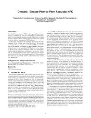
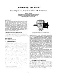
Figure 1: A data center network and a detailed<br />
illustration of a ToR (Top of Rack) switch connected<br />
to multiple rack-mounted servers<br />
results. Section 7 discusses the extension of <strong>IC<strong>TCP</strong></strong>.<br />
Section 8 presents related work. F<strong>in</strong>ally, Section 9 concludes<br />
the paper.<br />
2. BACKGROUND AND MOTIVATION<br />
<strong>TCP</strong> <strong>in</strong>cast has been identified and described by Nagle<br />
et al. [12] <strong>in</strong> distributed storage clusters. In distributed<br />
file systems, files are stored at multiple servers.<br />
<strong>TCP</strong> <strong>in</strong>cast congestion occurs when multiple blocks of<br />
a file are fetched from multiple servers. Several application<br />
specific solutions have been proposed <strong>in</strong> the context<br />
of parallel file system. With recent progresses on data<br />
center network<strong>in</strong>g, <strong>TCP</strong> <strong>in</strong>cast problem <strong>in</strong> data center<br />
networks has become a practical issue. S<strong>in</strong>ce there<br />
are various data center applications, a transport layer<br />
solution can free application from build<strong>in</strong>g their own<br />
solutions and is there<strong>for</strong>e preferred.<br />
In this Section, we first briefly <strong>in</strong>troduce the <strong>TCP</strong><br />
<strong>in</strong>cast problem, we then illustrate our observations <strong>for</strong><br />
<strong>TCP</strong> characteristics on high-bandwidth, low-latency network,<br />
and also the root cause of packet loss of <strong>in</strong>cast<br />
congestion. After observ<strong>in</strong>g <strong>TCP</strong> receive w<strong>in</strong>dow is a<br />
right controller to avoid congestion, we seek <strong>for</strong> a general<br />
<strong>TCP</strong> receive w<strong>in</strong>dow adjustment algorithm.<br />
2.1 <strong>TCP</strong> <strong>in</strong>cast congestion<br />
In Figure 1, we show a typical data center network<br />
structure. There are three layers of switches/routers:<br />
ToR (Top of Rack) switch, Aggregate switch and Aggregate<br />
router. We also show a detailed case <strong>for</strong> a ToR<br />
connected to dozens of servers. In a typical setup, the<br />
number of servers under the same ToR is from 44 to 48,<br />
and the ToR switch is a 48-port Gigabit switch with<br />
one or multiple 10 Gigabit upl<strong>in</strong>ks.<br />
<strong>Incast</strong> congestion happens when multiple send<strong>in</strong>g servers<br />
under the same ToR switch send data to one receiver<br />
server simultaneously. The amount of data transmitted<br />
by each connection is relatively small, e.g, 64kbytes. In<br />
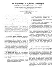
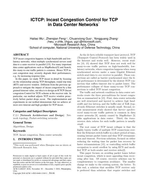
Figure 2, we show the goodput achieved on those multiple<br />
connections versus the number send<strong>in</strong>g servers.<br />
Note that we use term goodput as it is obta<strong>in</strong>ed and<br />
observed at application layer. The results are mea-<br />
1 U<br />
1 U<br />
1 U<br />
1 U<br />
1 U
<strong>TCP</strong> goodput (Mbps)<br />
1000<br />
900<br />
800<br />
700<br />
600<br />
500<br />
400<br />
300<br />
200<br />
100<br />
data per sender=64kbytes<br />
data per sender=128kbytes<br />
data per sender=256kbytes<br />
0<br />
0 4 8 12 16 20 24 28 32 36 40 44 48<br />
Number of senders <strong>in</strong> parallel<br />
Figure 2: The total goodput of multiple barrier<br />
synchronized <strong>TCP</strong> connections versus the number<br />
of senders, where the data traffic volume per<br />
sender is a fixed amount<br />
sured on a testbed with 47 Dell servers connected to one<br />
Quanta LB4G 48-port Gigabit switch. Those multiple<br />
connections are barrier synchronized. We observe similar<br />
goodput trends <strong>for</strong> three different traffic amounts<br />
per server, but with slightly different transition po<strong>in</strong>ts.<br />
Note that <strong>in</strong> our setup each connection has a same traffic<br />
amount with the number of senders <strong>in</strong>creas<strong>in</strong>g, which<br />
is used <strong>in</strong> [13]. [15] uses another setup that the total<br />
traffic amount of all senders is a fixed one. Here we just<br />
illustrate the problem and will show the results <strong>for</strong> both<br />
setups <strong>in</strong> Section 6.<br />
<strong>TCP</strong> throughput is severely degraded on <strong>in</strong>cast congestion,<br />
s<strong>in</strong>ce one ore more <strong>TCP</strong> connections experience<br />
timeout caused by packet drops. <strong>TCP</strong> <strong>in</strong>cast scenario<br />
is common <strong>for</strong> data center applications. For example,<br />
<strong>for</strong> search <strong>in</strong>dex<strong>in</strong>g we need to count the frequency of<br />
a specific word <strong>in</strong> multiple documents. This job is distributed<br />
to multiple servers and each server is responsible<br />
<strong>for</strong> some documents on its local disk. Only after<br />
all servers return their counters to the receiv<strong>in</strong>g server,<br />
the f<strong>in</strong>al result can be generated.<br />
2.2 <strong>TCP</strong> goodput, receive w<strong>in</strong>dow and RTT<br />
<strong>TCP</strong> receive w<strong>in</strong>dow is <strong>in</strong>troduced <strong>for</strong> <strong>TCP</strong> flow control,<br />
i.e., prevent<strong>in</strong>g faster sender from overflow<strong>in</strong>g slow<br />
receiver’s buffer. The receive w<strong>in</strong>dow size determ<strong>in</strong>es<br />
the maximal number of bytes that the sender can transmit<br />
without receiv<strong>in</strong>g receiver’s ACK. Previous study<br />
[10] mentioned that a small static <strong>TCP</strong> receive buffer<br />
may throttle <strong>TCP</strong> throughput and thus prevent <strong>TCP</strong><br />
<strong>in</strong>cast congestion collapse. However, a static buffer<br />
can’t work <strong>for</strong> changed number of connections and can’t<br />
handle the dynamics on applications’ requirements.<br />
As <strong>TCP</strong> receive w<strong>in</strong>dow has the ability to control<br />
<strong>TCP</strong> throughput and thus prevent <strong>TCP</strong> <strong>in</strong>cast collapse,<br />
we consider how to dynamically adjust it to the proper<br />
value. We start from w<strong>in</strong>dow based congestion control<br />
used <strong>in</strong> <strong>TCP</strong>. As we know, <strong>TCP</strong> uses slow start and<br />
Throughput(Mbps) of a <strong>TCP</strong> connection<br />
1000<br />
800<br />
600<br />
400<br />
200<br />
0<br />
Goodput<br />
RTT<br />
0 5 10 15 20 25 30 35 40<br />
0<br />
45<br />
Receiver W<strong>in</strong>dow Size (rwnd) counted by MSS<br />
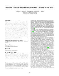
Figure 3: The goodput and RTT of one <strong>TCP</strong><br />
connection over Gigabit Ethernet versus the receive<br />
w<strong>in</strong>dow size<br />
congestion avoidance to adjust congestion w<strong>in</strong>dow at<br />
sender side. Directly apply<strong>in</strong>g such technique to <strong>TCP</strong><br />
receive w<strong>in</strong>dow adjustment certa<strong>in</strong>ly won’t help as it<br />
still requires either losses or ECN marks to trigger w<strong>in</strong>dow<br />
decrease, otherwise the w<strong>in</strong>dow keeps <strong>in</strong>creas<strong>in</strong>g.<br />
Different from <strong>TCP</strong>’s congestion avoidance, <strong>TCP</strong> Vegas<br />
adjusts its w<strong>in</strong>dow accord<strong>in</strong>g to changes of RTT.<br />
<strong>TCP</strong> Vegas makes the assumption that <strong>TCP</strong> RTT is<br />
stable be<strong>for</strong>e it reaches network available bandwidth.<br />
That is to say, the <strong>in</strong>crease of RTT is only caused by<br />
packet queue<strong>in</strong>g at bottleneck buffer. <strong>TCP</strong> Vegas then<br />
adjusts w<strong>in</strong>dow to keep <strong>TCP</strong> throughput close to the<br />
available bandwidth, by keep<strong>in</strong>g the RTT <strong>in</strong> a reasonable<br />
range. Un<strong>for</strong>tunately, we f<strong>in</strong>d that the <strong>in</strong>crease<br />
of <strong>TCP</strong> RTT <strong>in</strong> high-bandwidth, low-latency network<br />
does not follow such assumption.<br />
In Figure 3, we show the throughput and RTT of one<br />
<strong>TCP</strong> connection between two servers under the same<br />
ToR Gigabit switch. The connection lasts <strong>for</strong> 10 seconds.<br />
We def<strong>in</strong>e the base RTT <strong>for</strong> a connection as the<br />
observed RTT when there is no other traffic and <strong>TCP</strong><br />
receive w<strong>in</strong>dow is one MSS (Maximum Segment Size).<br />
In our testbed, the base RTT is around 100 microseconds,<br />
which is much smaller than RTT observed <strong>in</strong> Internet.<br />
From Figure 3, we observe that RTT <strong>in</strong>creases<br />
as the <strong>TCP</strong> receive w<strong>in</strong>dow <strong>in</strong>creases, when throughput<br />
is smaller than the available bandwidth (l<strong>in</strong>k capacity<br />
<strong>in</strong> this case). There<strong>for</strong>e, <strong>in</strong> data center network, even<br />
if there is no cross traffic, an <strong>in</strong>crease on RTT can’t be<br />
regarded as a signal <strong>for</strong> <strong>TCP</strong> throughput reach<strong>in</strong>g available<br />
bandwidth. For example, the base RTT is around<br />
100us, and the RTT <strong>in</strong>creases to 460us with maximal<br />
throughput at 906Mbps.<br />
Given that the base RTT is near 100us and a full<br />
bandwidth of Gigabit Ethernet, the base BDP (Bandwidth<br />
Delay Product) without queue is around 12.5k<br />
bytes (100us*1Gbps). For an <strong>in</strong>cast scenario, multiple<br />
<strong>TCP</strong> connections share this small pipe, i.e., the base<br />
500<br />
400<br />
300<br />
200<br />
100<br />
RTT(us)
BDP and queue are shared by those connections. The<br />
small base BDP but high bandwidth <strong>for</strong> multiple <strong>TCP</strong><br />
connections is the reason that the switch buffer easily<br />
goes to overflow. Meanwhile, we also observe that the<br />
receive w<strong>in</strong>dow size should be controlled s<strong>in</strong>ce the total<br />
receive w<strong>in</strong>dow size of all connections should be no<br />
greater than base BDP plus the queue size. Otherwise<br />
packets may get dropped.<br />
3. DESIGN RATIONALE<br />
Our goal is to improve <strong>TCP</strong> per<strong>for</strong>mance <strong>for</strong> <strong>in</strong>cast<br />
congestion, <strong>in</strong>stead of <strong>in</strong>troduc<strong>in</strong>g a new transport layer<br />
protocol. Although we focus on <strong>TCP</strong> <strong>in</strong> data center<br />
network, we still require no new <strong>TCP</strong> option or modification<br />
to <strong>TCP</strong> header. This is to keep backward compatibility,<br />
and to make our scheme general enough to<br />
handle the <strong>in</strong>cast congestion <strong>in</strong> future high-bandwidth,<br />
low-latency network.<br />
Previous work focused on how to reduce the impact<br />
of timeout, which is caused by large number of packet<br />
losses on <strong>in</strong>cast congestion. We’ve shown that the basic<br />
RTT <strong>in</strong> data center network is hundreds of microseconds,<br />
and the bandwidth is Gigabit and 10 Gigabit<br />
<strong>in</strong> near future. Given such high-bandwidth and lowlatency,<br />
we focus on how to per<strong>for</strong>m congestion avoidance<br />
to prevent switch buffer overflow. Avoid<strong>in</strong>g unnecessary<br />
buffer overflow significantly reduces <strong>TCP</strong> timeouts<br />
and saves unnecessary retransmissions.<br />
We focus on the classical <strong>in</strong>cast scenario where dozens<br />
of servers connected by a Gigabit Ethernet switch. In<br />
this scenario, the congestion po<strong>in</strong>t happens right be<strong>for</strong>e<br />
the receiver. This is to say, the switch port <strong>in</strong> congestion<br />
is actually the last-hop of all <strong>TCP</strong> connections at the<br />
<strong>in</strong>cast receiver. Recent measurement study[9] showed<br />
that this scenario exists <strong>in</strong> data center networks, and<br />
the traffic between servers under the same ToR switch<br />
is actually one of the most significant traffic pattern<br />
<strong>in</strong> data center, as locality has been considered <strong>in</strong> job<br />
distribution. Whether <strong>in</strong>cast exists <strong>in</strong> more advanced<br />
data center topology like recent proposals DCell[7], Fattree[1]<br />
and BCube[6] is not the focus of this paper.<br />
From Figure 3, we observe that <strong>TCP</strong> receive w<strong>in</strong>dow<br />
can be used to throttle the <strong>TCP</strong> throughput, which can<br />
be leveraged to handle <strong>in</strong>cast congestion although the<br />
receive w<strong>in</strong>dow is orig<strong>in</strong>ally designed <strong>for</strong> flow control.<br />
In short, our <strong>in</strong>cast quench<strong>in</strong>g scheme is to design a<br />
w<strong>in</strong>dow based congestion control algorithm at <strong>TCP</strong> receiver<br />
side, given the <strong>in</strong>cast scenario we have described,<br />
and the requirements we made. The benefit of an <strong>in</strong>cast<br />
congestion control scheme at receiver is that the<br />
receiver knows how much throughput it has achieved<br />
and how much available bandwidth left. While the difficulty<br />
and also the challenge at receiver side is that<br />
an overly controlled w<strong>in</strong>dow may constra<strong>in</strong> <strong>TCP</strong> per<strong>for</strong>mance<br />
while less controlled w<strong>in</strong>dow may not prevent<br />
<strong>in</strong>cast congestion.<br />
As the base RTT is at hundreds of microseconds <strong>in</strong><br />
data center [2], our algorithm is restricted to adjust receive<br />
w<strong>in</strong>dow only <strong>for</strong> <strong>TCP</strong> flows with RTT less than<br />
2ms. This constra<strong>in</strong>t is designed to focus on low-latency<br />
flows. In particular, if a server <strong>in</strong> a data center communicates<br />
with servers with<strong>in</strong> this data center and servers<br />
<strong>in</strong> the Internet simultaneously, our RTT constra<strong>in</strong>t leaves<br />
those long RTT (and low throughput) <strong>TCP</strong> flows untouched.<br />
It also implies that some <strong>in</strong>com<strong>in</strong>g flows may<br />
not follow our congestion control. We will show the robustness<br />
of our algorithm with background (even UDP)<br />
traffic <strong>in</strong> Section 6.<br />
We summarize the follow<strong>in</strong>g three observations which<br />
<strong>for</strong>m the base <strong>for</strong> <strong>IC<strong>TCP</strong></strong>.<br />
First, the available bandwidth at receiver side is the<br />
signal <strong>for</strong> receiver to do congestion control. As <strong>in</strong>cast<br />
congestion happens at the last-hop, the <strong>in</strong>cast receiver<br />
should detect such receiv<strong>in</strong>g throughput burst<strong>in</strong>ess and<br />
control the throughput to avoid potential <strong>in</strong>cast congestion.<br />
If the <strong>TCP</strong> receiver needs to <strong>in</strong>crease the <strong>TCP</strong><br />
receive w<strong>in</strong>dow, it should also predict whether there<br />
is enough available bandwidth to support the <strong>in</strong>crease.<br />
Furthermore, the receive w<strong>in</strong>dow <strong>in</strong>crease of all connections<br />
should be jo<strong>in</strong>tly considered.<br />
Second, the frequency of receive w<strong>in</strong>dow based congestion<br />
control should be made accord<strong>in</strong>g to the perflow<br />
feedback-loop delay <strong>in</strong>dependently. In pr<strong>in</strong>ciple,<br />
the congestion control dynamics of one <strong>TCP</strong> connection<br />
can be regarded as a control system, where the feedback<br />
delay is the RTT of that <strong>TCP</strong> connection. When the receive<br />
w<strong>in</strong>dow is adjusted, it takes at least one RTT time<br />
be<strong>for</strong>e the data packets follow<strong>in</strong>g the newly adjusted receive<br />
w<strong>in</strong>dow arrive. Thus, the control <strong>in</strong>terval should<br />
be larger than one RTT time, which changes dynamically<br />
accord<strong>in</strong>g to the queue<strong>in</strong>g delay and also system<br />
overhead.<br />
Third, a receive w<strong>in</strong>dow based scheme should adjust<br />
the w<strong>in</strong>dow accord<strong>in</strong>g to both l<strong>in</strong>k congestion status<br />
and also application requirement. The receive w<strong>in</strong>dow<br />
should not restrict <strong>TCP</strong> throughput when there is<br />
available bandwidth, and should throttle <strong>TCP</strong> throughput<br />
be<strong>for</strong>e <strong>in</strong>cast congestion happens. Consider a scenario<br />
where a <strong>TCP</strong> receive w<strong>in</strong>dow is <strong>in</strong>creased to a<br />
large value but is not decreased after application requirement<br />
is gone, then if the application resumes, congestion<br />
may happen with traffic surge on such a large<br />
receive w<strong>in</strong>dow. There<strong>for</strong>e, the receiver should differentiate<br />
whether a <strong>TCP</strong> receive w<strong>in</strong>dow over-satisfies<br />
the achieved throughput on a <strong>TCP</strong> connection, and decrease<br />
its receive w<strong>in</strong>dow if so.<br />
With these three observations, our receive w<strong>in</strong>dow<br />
based <strong>in</strong>cast congestion control <strong>in</strong>tends to set a proper<br />
receive w<strong>in</strong>dow to all <strong>TCP</strong> connections shar<strong>in</strong>g the same<br />
last-hop. Consider<strong>in</strong>g that there are many <strong>TCP</strong> con-
nections shar<strong>in</strong>g the bottlenecked last-hop be<strong>for</strong>e <strong>in</strong>cast<br />
congestion, we adjust <strong>TCP</strong> receive w<strong>in</strong>dow to make<br />
those connections share the bandwidth fairly. This is<br />
because <strong>in</strong> data center, those parallel <strong>TCP</strong> connections<br />
may belong to the same job and the last f<strong>in</strong>ished one<br />
determ<strong>in</strong>es the f<strong>in</strong>al per<strong>for</strong>mance. Note that the fairness<br />
controller between <strong>TCP</strong> flows is <strong>in</strong>dependent of<br />
receive w<strong>in</strong>dow adjustment <strong>for</strong> <strong>in</strong>cast congestion avoidance,<br />
so that any other fairness category can be deployed<br />
if needed.<br />
4. <strong>IC<strong>TCP</strong></strong> ALGORITHM<br />
<strong>IC<strong>TCP</strong></strong> provides a receive w<strong>in</strong>dow based congestion<br />
control algorithm <strong>for</strong> <strong>TCP</strong> at end-system. The receive<br />
w<strong>in</strong>dow of all low-RTT <strong>TCP</strong> connections are jo<strong>in</strong>tly adjusted<br />
to control throughput on <strong>in</strong>cast congestion. Our<br />
<strong>IC<strong>TCP</strong></strong> algorithm closely follow the design po<strong>in</strong>ts made<br />
<strong>in</strong> Section 3. In this Section, we describe how to set the<br />
receive w<strong>in</strong>dow of a <strong>TCP</strong> connection, and we discuss<br />
how to implement our algorithm at next Section.<br />
4.1 <strong>Control</strong> trigger: available bandwidth<br />
Without loss of generality, we assume there is one<br />
<strong>in</strong>terface on a receiver server, and def<strong>in</strong>e symbols correspond<strong>in</strong>g<br />
to that <strong>in</strong>terface. Our algorithm can be applied<br />
<strong>for</strong> the scenario that the receiver has multiple <strong>in</strong>terfaces,<br />
while the connections on each <strong>in</strong>terface should<br />
per<strong>for</strong>m our algorithm <strong>in</strong>dependently.<br />
Assume the l<strong>in</strong>k capacity of the <strong>in</strong>terface on receiver<br />
server is C. Def<strong>in</strong>e the bandwidth of total <strong>in</strong>com<strong>in</strong>g<br />
traffic observed on that <strong>in</strong>terface as BWT , which <strong>in</strong>cludes<br />
all types of packets, i.e., broadcast, multicast,<br />
unicast of UDP or <strong>TCP</strong>, etc. Then we def<strong>in</strong>e the available<br />
bandwidth BWA on that <strong>in</strong>terface as,<br />
BWA = max(0, α ∗ C − BWT ) (1)<br />
where α ∈ [0, 1] is a parameter to absorb potential<br />
oversubscribed bandwidth dur<strong>in</strong>g w<strong>in</strong>dow adjustment.<br />
In all our implementation and experiment, we have a<br />
fixed sett<strong>in</strong>g with α = 0.9.<br />
In <strong>IC<strong>TCP</strong></strong>, we use available bandwidth BWA as the<br />
quota of all <strong>in</strong>com<strong>in</strong>g connections to <strong>in</strong>crease receive<br />
w<strong>in</strong>dow <strong>for</strong> higher throughput. Each flow should estimate<br />
the potential throughput <strong>in</strong>crease be<strong>for</strong>e its receive<br />
w<strong>in</strong>dow should be <strong>in</strong>creased. Only when there is<br />
enough quota (BWA), the receive w<strong>in</strong>dow can be <strong>in</strong>creased,<br />
and the correspond<strong>in</strong>g quota is consumed to<br />
prevent bandwidth oversubscription.<br />
To estimate the available bandwidth on the <strong>in</strong>terface<br />
and provide a quota <strong>for</strong> later receive w<strong>in</strong>dow <strong>in</strong>crease,<br />
we divide time <strong>in</strong>to slots. Each slot consists of two<br />
sub-slots with the same length T . For each network<br />
<strong>in</strong>terface, we measure all the traffic received <strong>in</strong> the first<br />
sub-slot, and use it to calculate the available bandwidth<br />
as quota <strong>for</strong> w<strong>in</strong>dow <strong>in</strong>crease on the second sub-slot.<br />
Global<br />
Connection i<br />
Connection j<br />
First Second<br />
subslot subslot<br />
RTTj<br />
RTTi<br />
Slot<br />
BWA estimated<br />
W<strong>in</strong>dow <strong>in</strong>crease <strong>in</strong> second subslot<br />
T T<br />
Two or more RTTi<br />
First<br />
subslot<br />
Second<br />
subslot<br />
Potential w<strong>in</strong>dow <strong>in</strong>crease time<br />
per connection <strong>in</strong>dependantly<br />
Time<br />
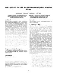
Figure 4: slotted time on global (all connections<br />
on that <strong>in</strong>terface) and two arbitrary <strong>TCP</strong> connections<br />
i/j are <strong>in</strong>dependent<br />
In Figure 4, the arrowed l<strong>in</strong>e marked as “Global” denotes<br />
the slot allocation <strong>for</strong> available bandwidth estimation<br />
on a network <strong>in</strong>terface. The first sub-slot is marked<br />
<strong>in</strong> gray color. In the time of first sub-slot, all connections’<br />
receive w<strong>in</strong>dow can’t be <strong>in</strong>creased (but can be<br />
decreased if needed). The second sub-slot is marked <strong>in</strong><br />
white <strong>in</strong> Figure 4. In the second sub-slot, the receive<br />
w<strong>in</strong>dow of any <strong>TCP</strong> connection can be <strong>in</strong>creased, but<br />
the total estimated <strong>in</strong>creased throughput of all connections<br />
<strong>in</strong> the second sub-slot must be less than the available<br />
bandwidth observed <strong>in</strong> the first sub-slot. Note that<br />
a decrease of any receive w<strong>in</strong>dow does not <strong>in</strong>crease the<br />
quota, as the quota will only be reset by <strong>in</strong>com<strong>in</strong>g traffic<br />
<strong>in</strong> the next first sub-slot. We discuss how to choose<br />
T and its relationship with per flow control <strong>in</strong>terval <strong>in</strong><br />
the next subsection.<br />
4.2 Per connection control <strong>in</strong>terval: 2*RTT<br />
In <strong>IC<strong>TCP</strong></strong>, each connection only adjusts its receive<br />
w<strong>in</strong>dow when there is an ACK send<strong>in</strong>g out on that connection.<br />
No additional <strong>TCP</strong> ACK packets are generated<br />
only <strong>for</strong> w<strong>in</strong>dow adjustment, so that no traffic is<br />
wasted. For a <strong>TCP</strong> connection, after an ACK is sent<br />
out, the data packet correspond<strong>in</strong>g to that ACK arrives<br />
one RTT later. As a control system, the latency on the<br />
feedback-loop is one RTT time of each <strong>TCP</strong> connection.<br />
Meanwhile, to estimate the throughput of a <strong>TCP</strong><br />
connection <strong>for</strong> receive w<strong>in</strong>dow adjustment, the shortest<br />
time scale is an RTT <strong>for</strong> that connection. There<strong>for</strong>e,<br />
the control <strong>in</strong>terval <strong>for</strong> a <strong>TCP</strong> connection is 2*RTT <strong>in</strong><br />
<strong>IC<strong>TCP</strong></strong>, as we need one RTT latency <strong>for</strong> that adjusted<br />
w<strong>in</strong>dow to take effect, and one additional RTT to measure<br />
the achieved throughput with that newly adjusted<br />
w<strong>in</strong>dow. Note that the w<strong>in</strong>dow adjustment <strong>in</strong>terval is<br />
per<strong>for</strong>med per connection. We use Connection i and<br />
j to represent two arbitrary <strong>TCP</strong> connections <strong>in</strong> Figure<br />
4, to show that one connection’s receive w<strong>in</strong>dows<br />
adjustment is <strong>in</strong>dependent with the other.<br />
The relationship of sub-slot length T and any flow’s
control <strong>in</strong>terval is as follows. S<strong>in</strong>ce the major purpose<br />
of available bandwidth estimation on the first sub-slot<br />
is to provide a quota <strong>for</strong> w<strong>in</strong>dow adjustment on the<br />
second sub-slot, the length T should be determ<strong>in</strong>ed<br />
by the control <strong>in</strong>tervals of all connections. We use a<br />
weighted averaged RTT of all <strong>TCP</strong> connections as T ,<br />
i.e., T = ∑<br />
i wiRT Ti. The weight wi is the normalized<br />
traffic volume of connection i over all traffic.<br />
In Figure 4, we illustrate the relationship of two arbitrary<br />
<strong>TCP</strong> connections i/j with RT Ti/j and the system<br />
estimation sub-<strong>in</strong>terval T . Each connection adjust its<br />
receive w<strong>in</strong>dow based on its observed RTT. The time <strong>for</strong><br />
a connection to <strong>in</strong>crease its receive w<strong>in</strong>dow is marked<br />
with an up arrow <strong>in</strong> Figure 4. For any <strong>TCP</strong> connection,<br />
if now time is <strong>in</strong> the second global sub-slot and it<br />
observes that the past time is larger than 2*RTT s<strong>in</strong>ce<br />
its last receive w<strong>in</strong>dow adjustment, it may <strong>in</strong>crease its<br />
w<strong>in</strong>dow based on newly observed <strong>TCP</strong> throughput and<br />
current available bandwidth. Note the RTT of each<br />
<strong>TCP</strong> connection is drawn as a fixed <strong>in</strong>terval <strong>in</strong> Figure<br />
4. This is just <strong>for</strong> illustration. We discuss how to obta<strong>in</strong><br />
accurate and live RTT at receiver side <strong>in</strong> Section 5.<br />
4.3 W<strong>in</strong>dow adjustment on s<strong>in</strong>gle connection<br />
For any <strong>IC<strong>TCP</strong></strong> connection, the receive w<strong>in</strong>dow is adjusted<br />
based on its <strong>in</strong>com<strong>in</strong>g measured throughput (denoted<br />
as bm ) and its expected throughput (denoted as<br />
be ). The measured throughput represents the achieved<br />
throughput on a <strong>TCP</strong> connection, also implies the current<br />
requirement of the application over that <strong>TCP</strong> connection.<br />
The expected throughput represents our expectation<br />
of the throughput on that <strong>TCP</strong> connection if<br />
the throughput is only constra<strong>in</strong>ed by receive w<strong>in</strong>dow.<br />
Our idea on receive w<strong>in</strong>dow adjustment is to <strong>in</strong>crease<br />
w<strong>in</strong>dow when the difference ratio of measured and expected<br />
throughput is small, while decrease w<strong>in</strong>dow when<br />
the difference ratio is large. Similar concept is <strong>in</strong>troduced<br />
<strong>in</strong> <strong>TCP</strong> Vegas [3] be<strong>for</strong>e but it uses throughput<br />
difference <strong>in</strong>stead of difference ratio, and it’s designed<br />
<strong>for</strong> congestion w<strong>in</strong>dow at sender side to pursue available<br />
bandwidth. <strong>IC<strong>TCP</strong></strong> w<strong>in</strong>dow adjustment is to set<br />
the receive w<strong>in</strong>dow of a <strong>TCP</strong> connection to a value<br />
that represents its current application’s requirement.<br />
Oversized receive w<strong>in</strong>dow is a hidden problem as the<br />
throughput of that connection may reach the expected<br />
one at any time, and the traffic surge may overflow the<br />
switch buffer, which is hard to predict and avoid.<br />
The measured throughput bm i is obta<strong>in</strong>ed and updated<br />
<strong>for</strong> every RTT on connection i. For every RTT on<br />
connection i, we obta<strong>in</strong> a sample of current throughput,<br />
denoted as bs i , calculated as total number of received<br />
bytes divided by the time <strong>in</strong>terval RT Ti. We smooth<br />
measured throughput us<strong>in</strong>g exponential filter as,<br />
b m i,new = max(b s i , β ∗ b m i,old + (1 − β) ∗ b s i ) (2)<br />
Note that the max procedure here is to make b m i updated<br />
quickly if receive w<strong>in</strong>dow is <strong>in</strong>creased, especially<br />
when w<strong>in</strong>dow is doubled. The expected throughput of<br />
connection i is obta<strong>in</strong>ed as,<br />
b e i = max(b m i , rwndi/RT Ti) (3)<br />
where rwndi and RT Ti are the receive w<strong>in</strong>dow and RTT<br />
<strong>for</strong> connection i respectively. We have the max procedure<br />
to ensure bm i ≤ bei .<br />
We def<strong>in</strong>e the ratio of throughput difference db i as the<br />
ratio of throughput difference of measured and expected<br />
throughput over the expected one <strong>for</strong> connection i.<br />
d b i = (b e i − b m i )/b e i<br />
By def<strong>in</strong>ition, we have bm i ≤ bei , thus dbi ∈ [0, 1].<br />
(4)<br />
We have two thresholds γ1 and γ2 (γ2 > γ1) to differentiate<br />
three cases <strong>for</strong> receive w<strong>in</strong>dow adjustment:<br />
1) d b i ≤ γ1 or d b i ≤ MSSi/rwndi 1 , <strong>in</strong>crease receive<br />
w<strong>in</strong>dow if it’s now <strong>in</strong> global second sub-slot and there<br />
is enough quota of available bandwidth on the network<br />
<strong>in</strong>terface. Decrease the quota correspond<strong>in</strong>gly if the<br />
receive w<strong>in</strong>dow is <strong>in</strong>creased.<br />
2) d b i > γ2, decrease receive w<strong>in</strong>dow by one MSS 2<br />
if this condition holds <strong>for</strong> three cont<strong>in</strong>uous RTT. The<br />
m<strong>in</strong>imal receive w<strong>in</strong>dow is 2*MSS.<br />
3) Otherwise, keep current receive w<strong>in</strong>dow.<br />
In all of our experiments, we have γ1 = 0.1 and<br />
γ2 = 0.5. Similar to <strong>TCP</strong>’s congestion w<strong>in</strong>dow <strong>in</strong>crease<br />
at sender, the <strong>in</strong>crease of the receive w<strong>in</strong>dow on any<br />
<strong>IC<strong>TCP</strong></strong> connection consists of two phases: slow start<br />
and congestion avoidance. If there is enough quota, <strong>in</strong><br />
slow start phase, the receive w<strong>in</strong>dow is doubled, while it<br />
is enlarged by at most one MSS <strong>in</strong> congestion avoidance<br />
phase. A newly established or long time idle connection<br />
is <strong>in</strong>itiated <strong>in</strong> slow start phase, whenever the above second<br />
and third case is met, or the first case is met but<br />
there is not enough quota on receiver side, the connection<br />
goes <strong>in</strong>to congestion avoidance phase.<br />
4.4 Fairness controller <strong>for</strong> multiple connections<br />
When the receiver detects that the available bandwidth<br />
BWA becomes smaller than a threshold, <strong>IC<strong>TCP</strong></strong><br />
starts to decrease the receiver w<strong>in</strong>dow of some selected<br />
connections to prevent congestion. Consider<strong>in</strong>g that<br />
multiple active <strong>TCP</strong> connections at the same time typically<br />
works <strong>for</strong> the same job <strong>in</strong> data center, we seek <strong>for</strong> a<br />
method that can achieve fair shar<strong>in</strong>g <strong>for</strong> all connections<br />
without sacrific<strong>in</strong>g throughput. Note that <strong>IC<strong>TCP</strong></strong> does<br />
not adjust receive w<strong>in</strong>dow <strong>for</strong> flows with RTT larger<br />
1 This means the throughput difference is less than one MSS<br />
with current receive w<strong>in</strong>dow. It’s designed to speed up <strong>in</strong>crease<br />
step when receive w<strong>in</strong>dow is relatively small.<br />
2,3 The decrease of only one MSS is to follow <strong>TCP</strong>’s design<br />
that the right-edge of sender’s buffer never left shifted when<br />
receive w<strong>in</strong>dow shr<strong>in</strong>ks. Note we decrease receive w<strong>in</strong>dow<br />
by an outgo<strong>in</strong>g ACK that acknowledges an MSS data.
than 2ms, so fairness is only considered among lowlatency<br />
flows.<br />
In our experiment, we decrease w<strong>in</strong>dow <strong>for</strong> fairness<br />
when BWA < 0.2C. This condition is designed <strong>for</strong><br />
high bandwidth network, where l<strong>in</strong>k capacity is underutilized<br />
<strong>for</strong> most of time. If there is still enough available<br />
bandwidth, the requirement of better fairness is<br />
not strong as potential impact on achieved throughput.<br />
We adjust receive w<strong>in</strong>dow to achieve fairness <strong>for</strong> <strong>in</strong>com<strong>in</strong>g<br />
<strong>TCP</strong> connections with low-latency on two folds:<br />
1) For w<strong>in</strong>dow decrease, we cut the receive w<strong>in</strong>dow by<br />
one MSS 3 , <strong>for</strong> some selected <strong>TCP</strong> connections. We select<br />
those connections that have receive w<strong>in</strong>dow larger<br />
than the average w<strong>in</strong>dow value of all connections. 2)<br />
For w<strong>in</strong>dow <strong>in</strong>crease, this is automatically achieved by<br />
our w<strong>in</strong>dow adjustment described <strong>in</strong> Section 4.3, as the<br />
receive w<strong>in</strong>dow is only <strong>in</strong>creased by one MSS on congestion<br />
avoidance.<br />
5. IMPLEMENTATION<br />
5.1 Software stack<br />
Ideally, <strong>IC<strong>TCP</strong></strong> should be <strong>in</strong>tegrated <strong>in</strong>to exist<strong>in</strong>g<br />
<strong>TCP</strong> stack, as it is an approach <strong>for</strong> <strong>TCP</strong> receive w<strong>in</strong>dow<br />
optimization to achieve better per<strong>for</strong>mance.<br />
Although the implementation of <strong>IC<strong>TCP</strong></strong> <strong>in</strong> <strong>TCP</strong> stack<br />
is natural, this paper chooses a different approach – develop<br />
<strong>IC<strong>TCP</strong></strong> as a NDIS driver on W<strong>in</strong>dows OS. The<br />
software stack is shown <strong>in</strong> Figure 5. The NDIS <strong>IC<strong>TCP</strong></strong><br />
driver is implemented <strong>in</strong> W<strong>in</strong>dows kernel, between <strong>TCP</strong>/<br />
IP and NIC (Network Interface Card) driver, known as a<br />
W<strong>in</strong>dows filter driver. Our NDIS driver <strong>in</strong>tercepts <strong>TCP</strong><br />
packets and modifies the receive w<strong>in</strong>dow size if needed.<br />
The f<strong>in</strong>al solution <strong>for</strong> <strong>IC<strong>TCP</strong></strong> should be <strong>in</strong> <strong>TCP</strong> module,<br />
while our implementation of <strong>IC<strong>TCP</strong></strong> <strong>in</strong> driver is to<br />
demonstrate its feasibility and per<strong>for</strong>mance.<br />
There are several benefits that can be achieved when<br />
<strong>IC<strong>TCP</strong></strong> is implemented <strong>in</strong> a driver: 1) It naturally supports<br />
the case <strong>for</strong> virtual mach<strong>in</strong>e, which is widely used<br />
<strong>in</strong> data center. We discuss this po<strong>in</strong>t <strong>in</strong> detail <strong>in</strong> next<br />
subsection. 2) <strong>IC<strong>TCP</strong></strong> needs the <strong>in</strong>com<strong>in</strong>g throughput<br />
<strong>in</strong> very short time scale (comparable to RTT at hundreds<br />
of microseconds) to estimate available bandwidth,<br />
and at a driver these <strong>in</strong><strong>for</strong>mation can be easily obta<strong>in</strong>ed.<br />
Note that the <strong>in</strong>com<strong>in</strong>g traffic <strong>in</strong>clude all types of traffic<br />
arrived on that <strong>in</strong>terface, besides <strong>TCP</strong>. 3) It does<br />
not touch <strong>TCP</strong>/IP implementation <strong>in</strong> W<strong>in</strong>dows kernel.<br />
As a quick and dirty solution, it supports all OS versions,<br />
<strong>in</strong>stead of patch<strong>in</strong>g one by one to get deployed<br />
<strong>in</strong> a large data center network with various <strong>TCP</strong> implementations.<br />
As shown <strong>in</strong> Figure 5, <strong>IC<strong>TCP</strong></strong> driver implementation<br />
conta<strong>in</strong>s 3 software modules: packet header parser/<br />
modifier, flow table and <strong>IC<strong>TCP</strong></strong> algorithm. The parser/<br />
modifer implements the functions both to check packet<br />
user<br />
kernel<br />
Packet header<br />
parser/modifier<br />
Applications<br />
<strong>TCP</strong>/IP<br />
<strong>IC<strong>TCP</strong></strong> NDIS driver<br />
NIC driver<br />
Flow table<br />
Algorithm<br />
Virtual<br />
mach<strong>in</strong>e<br />
space<br />
Virtual<br />
Mach<strong>in</strong>e<br />
Virtual<br />
NIC<br />
Virtual<br />
Mach<strong>in</strong>e<br />
<strong>TCP</strong>/IP <strong>TCP</strong>/IP<br />
Virtual<br />
NIC<br />
Host<br />
space <strong>IC<strong>TCP</strong></strong> driver <strong>in</strong> Virtual mach<strong>in</strong>e host<br />
NIC driver <strong>in</strong> Virtual mach<strong>in</strong>e host<br />
Figure 5: Modules <strong>in</strong> <strong>IC<strong>TCP</strong></strong> driver and software<br />
stack <strong>for</strong> virtual mach<strong>in</strong>e support<br />
header and modify receive w<strong>in</strong>dow on <strong>TCP</strong> header. Flow<br />
table ma<strong>in</strong>ta<strong>in</strong>s the key data structure <strong>in</strong> the <strong>IC<strong>TCP</strong></strong><br />
driver. A flow is identified by a 5-tuple: source /dest<strong>in</strong>ation<br />
IP address, source/dest<strong>in</strong>ation port and protocol.<br />
The flow table stores per flow <strong>in</strong><strong>for</strong>mation <strong>for</strong> all<br />
the active flows. For a <strong>TCP</strong> flow, its entry is removed<br />
from the table if a FIN/RST packet is observed, or no<br />
packets parsed <strong>for</strong> 15 m<strong>in</strong>utes. The algorithm part implements<br />
all the algorithms described <strong>in</strong> Section 4.<br />
The work flow of an <strong>IC<strong>TCP</strong></strong> driver is as follows. 1)<br />
When the <strong>in</strong>termediate driver captures packets through<br />
either NDIS send<strong>in</strong>g or receiv<strong>in</strong>g entry, it will redirect<br />
the packet to header parser module; 2) Packet header<br />
is parsed and correspond<strong>in</strong>g <strong>in</strong><strong>for</strong>mation is updated on<br />
flow table; 3) <strong>IC<strong>TCP</strong></strong> algorithm module is responsible<br />
<strong>for</strong> receive w<strong>in</strong>dow calculation. 4) If a <strong>TCP</strong> ACK packet<br />
is sent out, the header modifier may change the receive<br />
w<strong>in</strong>dow field <strong>in</strong> <strong>TCP</strong> header if needed.<br />
Our <strong>IC<strong>TCP</strong></strong> driver does not <strong>in</strong>troduce extra CPU<br />
overhead <strong>for</strong> packet checksum when the receive w<strong>in</strong>dow<br />
is modified, as the checksum calculation is loaded to<br />
NIC on hardware, which is a normal setup <strong>in</strong> data center.<br />
Besides, there is no packet reordered <strong>in</strong> our driver.<br />
Although it’s not the focus of this paper, we measured<br />
the CPU overhead <strong>in</strong>troduced by our filter driver on a<br />
Dell server PowerEdge R200, Xeon (4CPU)@2.8GhHz,<br />
8G Memory, and compared with the case that our driver<br />
is not <strong>in</strong>stalled. The overhead is around 5-6% <strong>for</strong> 1Gbps<br />
throughput, and less than 1% <strong>for</strong> 100Mbps throughput.<br />
5.2 Support <strong>for</strong> Virtual Mach<strong>in</strong>es<br />
Virtual mach<strong>in</strong>e is widely used <strong>in</strong> data centers. When<br />
virtual mach<strong>in</strong>e is used, the physical NIC capacity on<br />
the host server is shared by multiple virtual NICs <strong>in</strong><br />
the virtual mach<strong>in</strong>es. The l<strong>in</strong>k capacity of a virtual<br />
NIC has to be configured, and usually as a static value<br />
<strong>in</strong> practice. However, to achieve better per<strong>for</strong>mance<br />
<strong>in</strong> multiplex<strong>in</strong>g, the total capacity of virtual NICs is<br />
typically configured higher than physical NIC capacity<br />
as most virtual mach<strong>in</strong>es won’t be busy at the same<br />
time. There<strong>for</strong>e, it br<strong>in</strong>gs a challenge to <strong>IC<strong>TCP</strong></strong> <strong>in</strong> virtual<br />
mach<strong>in</strong>e, as the observed virtual l<strong>in</strong>k capacity and<br />
available bandwidth does not represent the real value.
One solution is to change the sett<strong>in</strong>gs of virtual mach<strong>in</strong>e<br />
NICs, and make the total capacity of all virtual<br />
NICs equal to that physical NIC. An alternative<br />
solution is to deploy a <strong>IC<strong>TCP</strong></strong> driver on virtual mach<strong>in</strong>e<br />
host server. The reason <strong>for</strong> such deployment is to<br />
achieve high per<strong>for</strong>mance on virtual mach<strong>in</strong>e multiplex<strong>in</strong>g.<br />
This is a special design <strong>for</strong> virtual mach<strong>in</strong>e case,<br />
and won’t get conflict even if <strong>IC<strong>TCP</strong></strong> has already been<br />
<strong>in</strong>tegrated <strong>in</strong>to <strong>TCP</strong> <strong>in</strong> virtual mach<strong>in</strong>es. The software<br />
stack of <strong>IC<strong>TCP</strong></strong> <strong>in</strong> virtual mach<strong>in</strong>e host is illustrated <strong>in</strong><br />
the right side of Figure 5, where all connections pass<strong>in</strong>g<br />
the physical NIC are jo<strong>in</strong>tly adjusted.<br />
5.3 Obta<strong>in</strong> f<strong>in</strong>e-gra<strong>in</strong>ed RTT at receiver<br />
<strong>IC<strong>TCP</strong></strong> is deployed at the <strong>TCP</strong> receiver side, and it<br />
requires to obta<strong>in</strong> <strong>TCP</strong> RTT to adjust receive w<strong>in</strong>dow.<br />
From the discussion <strong>in</strong> Section 2.2, we need a live RTT<br />
as it changes with throughput.<br />
We def<strong>in</strong>e the reverse RTT as the RTT after a exponential<br />
filter at the <strong>TCP</strong> receiver side. By def<strong>in</strong>ition,<br />
the reverse RTT is close to the RTT exponentially filtered<br />
at the <strong>TCP</strong> sender side. The reverse RTT can be<br />
obta<strong>in</strong>ed if there is data traffic on both directions. Consider<strong>in</strong>g<br />
the data traffic on reverse direction may not be<br />
enough to keep obta<strong>in</strong><strong>in</strong>g live reverse RTT, we use <strong>TCP</strong><br />
timestamp to obta<strong>in</strong> the RTT on reverse direction.<br />
Un<strong>for</strong>tunately, the RTT implementation <strong>in</strong> exist<strong>in</strong>g<br />
<strong>TCP</strong> module uses a clock on milliseconds granularity.<br />
To obta<strong>in</strong> an accurate RTT <strong>for</strong> <strong>IC<strong>TCP</strong></strong> <strong>in</strong> data center<br />
network, the granularity should be at microseconds.<br />
There<strong>for</strong>e, we modify the timestamp counter <strong>in</strong>to 100ns<br />
granularity to obta<strong>in</strong> live and accurate RTT. Note that<br />
this does not <strong>in</strong>troduce extra overhead as such granularity<br />
time is available on W<strong>in</strong>dows kernel. We believe<br />
similar approach can be taken <strong>in</strong> other OS. Our change<br />
of time granularity on <strong>TCP</strong> timestamp follows the requirements<br />
by RFC1323[8].<br />
6. EXPERIMENTAL RESULTS<br />
We deployed a testbed with 47 servers and one Quanta<br />
LB4G 48-port Gigabit Ethernet switch. The topology<br />
of our testbed is the same as the one shown <strong>in</strong> the right<br />
side of Figure 1, where 47 servers connects to the 48port<br />
Gigabit Ethernet switch with a Gigabit Ethernet<br />
<strong>in</strong>terface respectively. The hardware profile of a server<br />
is with 2.2G Intel Xeon CPUs E5520 (two cores), 32G<br />
RAM, 1T hard disk, and one Broadcom BCM5709C<br />
NetXtreme II Gigabit Ethernet NIC (Network Interface<br />
Card). The OS of each server is W<strong>in</strong>dows Server 2008<br />
R2 Enterprise 64-bit version. The CPU, Memory and<br />
hard disk were never a bottleneck <strong>in</strong> any of our experiments.<br />
We use iperf to construct the <strong>in</strong>cast scenario<br />
where multiple send<strong>in</strong>g servers generate <strong>TCP</strong> traffic to<br />
a receiv<strong>in</strong>g server under the same switch. The servers<br />
<strong>in</strong> our testbed have their own background <strong>TCP</strong> con-<br />
nections <strong>for</strong> various services, but the background traffic<br />
amount is very small compared to our generated traffic.<br />
The testbed is <strong>in</strong> an enterprise network with normal<br />
background broadcast traffic.<br />
All comparisons are between a full implementation<br />
of <strong>IC<strong>TCP</strong></strong> described <strong>in</strong> Section 5 and a state-of-the-art<br />
<strong>TCP</strong> New Reno with SACK implementation on W<strong>in</strong>dows<br />
Server. The default timeout value of <strong>TCP</strong> on<br />
W<strong>in</strong>dows server is 300 milliseconds (ms). Note that<br />
all the <strong>TCP</strong> stacks are the same <strong>in</strong> our experiments, as<br />
<strong>IC<strong>TCP</strong></strong> is implemented <strong>in</strong> a filter driver at receiver side.<br />
6.1 Fixed traffic volume per server with the<br />
number of senders <strong>in</strong>creas<strong>in</strong>g<br />
The first <strong>in</strong>cast scenario we consider is that a number<br />
of senders generate the same amount of <strong>TCP</strong> traffic to<br />
a specific receiver under the same switch. Same as the<br />
setup <strong>in</strong> [13] and [4], we fix the traffic amount generated<br />
per send<strong>in</strong>g server.<br />
The <strong>TCP</strong> connections are barrier synchronized per<br />
round, i.e., each round f<strong>in</strong>ishes only after all <strong>TCP</strong> connections<br />
<strong>in</strong> it have f<strong>in</strong>ished. The goodput shown is the<br />
averaged value of 100 experimental rounds. We observe<br />
the <strong>in</strong>cast congestion: with the number of send<strong>in</strong>g<br />
servers <strong>in</strong>creas<strong>in</strong>g, the goodput per round actually<br />
drops due to <strong>TCP</strong> timeout on some connections. The<br />
smallest number of send<strong>in</strong>g servers to trigger <strong>in</strong>cast congestion<br />
varies with the traffic amount generated per<br />
server: larger data amount, smaller number of send<strong>in</strong>g<br />
servers to trigger <strong>in</strong>cast congestion.<br />
6.1.1 <strong>IC<strong>TCP</strong></strong> with m<strong>in</strong>imal receive w<strong>in</strong>dow at 2MSS<br />
Under the same setup, the per<strong>for</strong>mance of <strong>IC<strong>TCP</strong></strong> is<br />
shown <strong>in</strong> Figure 6. We observe that <strong>IC<strong>TCP</strong></strong> achieves<br />
smooth and <strong>in</strong>creas<strong>in</strong>g goodput with the number of<br />
send<strong>in</strong>g servers <strong>in</strong>creas<strong>in</strong>g. Larger data amount per<br />
send<strong>in</strong>g server results <strong>in</strong> slightly higher goodput achieved.<br />
The averaged goodput of <strong>IC<strong>TCP</strong></strong> shows that <strong>in</strong>cast congestion<br />
is effectively throttled. And the goodput of<br />
<strong>IC<strong>TCP</strong></strong> with various number of send<strong>in</strong>g servers and traffic<br />
amount per send<strong>in</strong>g servers show that our algorithm<br />
adapts well to different traffic requirements.<br />
We observe that the goodput of <strong>TCP</strong> be<strong>for</strong>e <strong>in</strong>cast<br />
congestion is actually higher than that of <strong>IC<strong>TCP</strong></strong>. For<br />
example, <strong>TCP</strong> achieves 879Mbps while <strong>IC<strong>TCP</strong></strong> achieves<br />
607Mbps with 4 send<strong>in</strong>g servers at 256kbytes per server.<br />
There are two reasons: 1) Dur<strong>in</strong>g connection <strong>in</strong>itiation<br />
phase (slow-start), <strong>IC<strong>TCP</strong></strong> <strong>in</strong>creases w<strong>in</strong>dow slower<br />
than <strong>TCP</strong>. Actually, <strong>IC<strong>TCP</strong></strong> <strong>in</strong>creases receive w<strong>in</strong>dow<br />
to double <strong>for</strong> at least every two RTTs while <strong>TCP</strong> <strong>in</strong>crease<br />
its send<strong>in</strong>g w<strong>in</strong>dow to double <strong>for</strong> every RTT.<br />
Besides, <strong>IC<strong>TCP</strong></strong> <strong>in</strong>creases receive w<strong>in</strong>dow by one MSS<br />
when available bandwidth is low. 2) The traffic amount<br />
per send<strong>in</strong>g server is very small, and thus the time<br />
taken <strong>in</strong> “slow-start” dom<strong>in</strong>ates the transmission time
Goodput (Mbps) with m<strong>in</strong> rwnd=2MSS<br />
1000<br />
900<br />
800<br />
700<br />
600<br />
500<br />
400<br />
300<br />
200<br />
100<br />
<strong>TCP</strong> data=64kbytes<br />
<strong>TCP</strong> data=128kbytes<br />
<strong>TCP</strong> data=256kbytes<br />
<strong>IC<strong>TCP</strong></strong> data=64kbytes<br />
<strong>IC<strong>TCP</strong></strong> data=128kbytes<br />
<strong>IC<strong>TCP</strong></strong> data=256kbytes<br />
0<br />
0 4 8 12 16 20 24 28 32 36 40 44 48<br />
Number of senders <strong>in</strong> parallel<br />
Figure 6: The total goodput of multiple barrier<br />
synchronized <strong>IC<strong>TCP</strong></strong>/<strong>TCP</strong> connections versus<br />
the number of senders, where the data traffic<br />
volume per sender is a fixed amount<br />
if <strong>in</strong>cast congestion does not happen. Note that low<br />
throughput of <strong>IC<strong>TCP</strong></strong> dur<strong>in</strong>g <strong>in</strong>itiation phase does not<br />
affect its throughput dur<strong>in</strong>g stable phase <strong>in</strong> larger time<br />
scale, e.g., hundreds of milliseconds, which will be evaluated<br />
<strong>in</strong> Section 6.4.<br />
To evaluate the effectiveness of <strong>IC<strong>TCP</strong></strong> on avoid<strong>in</strong>g<br />
timeout, we use the ratio of the number of experimental<br />
rounds experienc<strong>in</strong>g at least one timeout 4 over the<br />
total number of rounds. The ratio of rounds with at<br />
least one timeout is shown <strong>in</strong> Figure 7. We observe<br />
that <strong>TCP</strong> quickly suffer <strong>for</strong> at least one timeout when<br />
<strong>in</strong>cast congestion happens, while the highest ratio <strong>for</strong><br />
<strong>IC<strong>TCP</strong></strong> experience timeout is 6%. Note that the results<br />
<strong>in</strong> Figure 7 shows that <strong>IC<strong>TCP</strong></strong> is better than DC<strong>TCP</strong>[2],<br />
as DC<strong>TCP</strong> quickly downgrades to the same as <strong>TCP</strong><br />
when the number of send<strong>in</strong>g servers is over 35 <strong>for</strong> static<br />
buffer case. The reason <strong>for</strong> <strong>IC<strong>TCP</strong></strong> to effectively reduce<br />
the possibility on timeout is that <strong>IC<strong>TCP</strong></strong> does congestion<br />
avoidance and it <strong>in</strong>creases receive w<strong>in</strong>dow only if<br />
there is enough available bandwidth on receiv<strong>in</strong>g server.<br />
DC<strong>TCP</strong> relies on ECN to detect congestion, so larger<br />
(dynamic) buffer is required to avoid buffer overflow<br />
dur<strong>in</strong>g control latency, i.e., the time be<strong>for</strong>e control takes<br />
effect.<br />
6.1.2 <strong>IC<strong>TCP</strong></strong> with m<strong>in</strong>imal receive w<strong>in</strong>dow at 1MSS<br />
<strong>IC<strong>TCP</strong></strong> has some possibility (although very small) to<br />
timeout, s<strong>in</strong>ce we have a 2MSS m<strong>in</strong>imal receive w<strong>in</strong>dow.<br />
In pr<strong>in</strong>ciple, with the number of connections become<br />
larger, the receive w<strong>in</strong>dow <strong>for</strong> each connection should<br />
become smaller proportionately. This is because the<br />
total BDP <strong>in</strong>clud<strong>in</strong>g the buffer size is actually shared<br />
by those connections, and the m<strong>in</strong>imal receive w<strong>in</strong>dow<br />
of those connections determ<strong>in</strong>es whether such shar<strong>in</strong>g<br />
4 Multiple senders experienc<strong>in</strong>g timeout <strong>in</strong> the same barrier<br />
does not degrade per<strong>for</strong>mance proportionately, as the connections<br />
are delivered <strong>in</strong> parallel.<br />
Ratio of <strong>TCP</strong> timeout(%)<br />
100<br />
90<br />
80<br />
70<br />
60<br />
50<br />
40<br />
30<br />
20<br />
10<br />
<strong>TCP</strong> data=64kbytes<br />
<strong>TCP</strong> data=128kbytes<br />
<strong>TCP</strong> data=256kbytes<br />
<strong>IC<strong>TCP</strong></strong> data=64kbytes<br />
<strong>IC<strong>TCP</strong></strong> data=128kbytes<br />
<strong>IC<strong>TCP</strong></strong> data=256kbytes<br />
0<br />
0 4 8 12 16 20 24 28 32 36 40 44<br />
Number of senders <strong>in</strong> parallel<br />
Figure 7: The ratio of experimental rounds that<br />
suffer at least one timeout<br />
Goodput (Mbps) with m<strong>in</strong> rwnd=1MSS<br />
1000<br />
900<br />
800<br />
700<br />
600<br />
500<br />
400<br />
300<br />
200<br />
100<br />
0<br />
<strong>IC<strong>TCP</strong></strong> goodput (64k)<br />
<strong>IC<strong>TCP</strong></strong> goodput (128k)<br />
<strong>IC<strong>TCP</strong></strong> goodput (256k)<br />
<strong>IC<strong>TCP</strong></strong> timeout (64k)<br />
<strong>IC<strong>TCP</strong></strong> timeout (128k)<br />
<strong>IC<strong>TCP</strong></strong> timeout (256k)<br />
4 8 12 16 20 24 28 32 36 40 44<br />
Number of senders <strong>in</strong> parallel<br />
Figure 8: <strong>IC<strong>TCP</strong></strong> goodput and ratio of experimental<br />
rounds suffer at least one timeout with<br />
m<strong>in</strong>imal receive w<strong>in</strong>dow as 1MSS<br />
may cause buffer overflow when the total BDP is not<br />
enough to support those connections.<br />
The per<strong>for</strong>mance of <strong>IC<strong>TCP</strong></strong> with m<strong>in</strong>imal receive w<strong>in</strong>dow<br />
at 1MSS is shown <strong>in</strong> Figure 8. We observe that<br />
timeout probability is 0, while the averaged throughput<br />
is lower than those with 2MSS m<strong>in</strong>imal receive w<strong>in</strong>dow.<br />
For example, <strong>for</strong> 40 send<strong>in</strong>g servers with 64kbytes per<br />
server, the goodput is 741Mbps <strong>for</strong> 2MSS as shown <strong>in</strong><br />
Figure 6, while 564Mbps <strong>for</strong> 1MSS as shown <strong>in</strong> Figure<br />
8. There<strong>for</strong>e, the m<strong>in</strong>imal receive w<strong>in</strong>dow is a tradeoff<br />
between higher averaged <strong>in</strong>cast goodput and lower<br />
timeout possibility. Note that the goodput here is only<br />
<strong>for</strong> very short time, 40*64k*8/564Mbps =36ms. For<br />
larger request data size and longer connection duration,<br />
<strong>IC<strong>TCP</strong></strong> actually achieves goodput closely to l<strong>in</strong>k capacity,<br />
which is shown <strong>in</strong> detail <strong>in</strong> Section 6.4.<br />
6.2 Fixed total traffic volume with the number<br />
of senders <strong>in</strong>creas<strong>in</strong>g<br />
The second scenario we consider is with the one discussed<br />
<strong>in</strong> [15, 2], where the total data volume of all<br />
servers is fixed and the number of send<strong>in</strong>g servers varies.<br />
We show the goodput and timeout ratio <strong>for</strong> both <strong>TCP</strong><br />
and <strong>IC<strong>TCP</strong></strong> under a fixed total traffic amount <strong>in</strong> Figure<br />
100<br />
90<br />
80<br />
70<br />
60<br />
50<br />
40<br />
30<br />
20<br />
10<br />
0<br />
Ratio of rounds with timeout (%)
Goodput (Mbps) with a fixed total amount<br />
1000<br />
900<br />
800<br />
700<br />
600<br />
500<br />
400<br />
300<br />
200<br />
100<br />
0<br />
<strong>TCP</strong> total data=2M<br />
<strong>TCP</strong> total data=8M<br />
<strong>IC<strong>TCP</strong></strong> total data=2M<br />
<strong>IC<strong>TCP</strong></strong> total data=8M<br />
4 8 12 16 20 24 28 32 36 40 44 48<br />
Number of senders <strong>in</strong> parallel<br />
Figure 9: Goodput of <strong>IC<strong>TCP</strong></strong> (with m<strong>in</strong>imal<br />
receive w<strong>in</strong>dow at 2MSS) and <strong>TCP</strong> under the<br />
case that the total data amount from all send<strong>in</strong>g<br />
servers is a fixed value<br />
Ratio of rounds with <strong>TCP</strong> timeout(%)<br />
100<br />
90<br />
80<br />
70<br />
60<br />
50<br />
40<br />
30<br />
20<br />
10<br />
0<br />
<strong>TCP</strong> total data=2M<br />
<strong>TCP</strong> total data=8M<br />
<strong>IC<strong>TCP</strong></strong> total data=2M<br />
<strong>IC<strong>TCP</strong></strong> total data=8M<br />
4 8 12 16 20 24 28 32 36 40 44 48<br />
Number of senders <strong>in</strong> parallel<br />
Figure 10: Ratio of timeout <strong>for</strong> <strong>IC<strong>TCP</strong></strong> (with<br />
m<strong>in</strong>imal receive w<strong>in</strong>dow at 2MSS) and <strong>TCP</strong> under<br />
the case that the total data amount from all<br />
send<strong>in</strong>g servers is a fixed value<br />
9 and 10. From Figure 9 we observe that the number<br />
of send<strong>in</strong>g servers to trigger <strong>in</strong>cast congestion is close<br />
<strong>for</strong> 2M and 8M bytes total traffic respectively. <strong>IC<strong>TCP</strong></strong><br />
greatly improves the goodput and controls timeout well.<br />
Note that we show the case <strong>for</strong> <strong>IC<strong>TCP</strong></strong> with m<strong>in</strong>imal<br />
receive w<strong>in</strong>dow at 2MSS and skip the case with 1MSS,<br />
as the timeout ratio is aga<strong>in</strong> 0% <strong>for</strong> 1MSS.<br />
6.3 <strong>Incast</strong> with high throughput background<br />
traffic<br />
In previous experiments, we do not explicit generate<br />
long term background traffic <strong>for</strong> <strong>in</strong>cast experiments. In<br />
the third scenario, we generate a long term <strong>TCP</strong> connection<br />
as background traffic to the same receiv<strong>in</strong>g server,<br />
and it occupies 900Mbps be<strong>for</strong>e <strong>in</strong>cast traffic starts.<br />
The goodput and timeout ratio of <strong>TCP</strong> and <strong>IC<strong>TCP</strong></strong><br />
are shown <strong>in</strong> Figure 11 and 12. Compared Figure 11<br />
with Figure 2, the throughput achieved by <strong>TCP</strong> be<strong>for</strong>e<br />
<strong>in</strong>cast congestion is slightly lower. <strong>IC<strong>TCP</strong></strong> also achieves<br />
slightly lower throughput when the number of send<strong>in</strong>g<br />
Goodput (Mbps) with a background <strong>TCP</strong><br />
900<br />
800<br />
700<br />
600<br />
500<br />
400<br />
300<br />
200<br />
100<br />
0<br />
<strong>TCP</strong> data=64kbytes<br />
<strong>TCP</strong> data=128kbytes<br />
<strong>TCP</strong> data=256kbytes<br />
<strong>IC<strong>TCP</strong></strong> data=64kbytes<br />
<strong>IC<strong>TCP</strong></strong> data=128kbytes<br />
<strong>IC<strong>TCP</strong></strong> data=256kbytes<br />
4 8 12 16 20 24 28 32 36 40 44 48<br />
Number of senders <strong>in</strong> parallel<br />
Figure 11: Goodput of <strong>IC<strong>TCP</strong></strong> (with m<strong>in</strong>imal receive<br />
w<strong>in</strong>dow at 2MSS) and <strong>TCP</strong> under the case<br />
with a background long term <strong>TCP</strong> connection<br />
Ratio of rounds with <strong>TCP</strong> timeout(%)<br />
100<br />
90<br />
80<br />
70<br />
60<br />
50<br />
40<br />
30<br />
20<br />
10<br />
0<br />
<strong>TCP</strong> data=64kbytes<br />
<strong>TCP</strong> data=128kbytes<br />
<strong>TCP</strong> data=256kbytes<br />
<strong>IC<strong>TCP</strong></strong> data=64kbytes<br />
<strong>IC<strong>TCP</strong></strong> data=128kbytes<br />
<strong>IC<strong>TCP</strong></strong> data=256kbytes<br />
4 8 12 16 20 24 28 32 36 40 44 48<br />
Number of senders <strong>in</strong> parallel<br />
Figure 12: Ratio of timeout <strong>for</strong> <strong>IC<strong>TCP</strong></strong> (with<br />
m<strong>in</strong>imal receive w<strong>in</strong>dow at 2MSS) and <strong>TCP</strong> under<br />
the case with a background long term <strong>TCP</strong><br />
connection<br />
serves is small. Compar<strong>in</strong>g Figure 12 with Figure 7,<br />
the timeout ratio with <strong>IC<strong>TCP</strong></strong> becomes slightly higher<br />
when there is a high throughput background connection<br />
ongo<strong>in</strong>g. This is because the available bandwidth<br />
becomes smaller and thus the <strong>in</strong>itiation of new connections<br />
is affected. We also obta<strong>in</strong> the experimental results<br />
<strong>for</strong> a background UDP connection at 200Mbps,<br />
and <strong>IC<strong>TCP</strong></strong> also per<strong>for</strong>ms well. We skip the results under<br />
background UDP <strong>for</strong> space limitation.<br />
6.4 Fairness and long term per<strong>for</strong>mance of <strong>IC<strong>TCP</strong></strong><br />
To evaluate the fairness of <strong>IC<strong>TCP</strong></strong> on multiple connections,<br />
we generate 5 <strong>IC<strong>TCP</strong></strong> flows to the same receiv<strong>in</strong>g<br />
server under the same switch. The flows are started<br />
sequentially with 20s <strong>in</strong>terval and 100s duration. The<br />
achieved goodput of those 5 <strong>IC<strong>TCP</strong></strong> flows are shown <strong>in</strong><br />
Figure 13. We observe that the fairness of <strong>IC<strong>TCP</strong></strong> on<br />
multiple connections is very good, and the total goodput<br />
of multiple connections is close to l<strong>in</strong>k capacity at<br />
1Gbps. Note that the goodput here is much larger than<br />
that shown <strong>in</strong> Figure 6, s<strong>in</strong>ce the traffic volume is much
Goodput (Mbps) with 5 <strong>IC<strong>TCP</strong></strong> flows<br />
1000<br />
900<br />
800<br />
700<br />
600<br />
500<br />
400<br />
300<br />
200<br />
100<br />
0<br />
flow1<br />
flow2<br />
flow3<br />
flow4<br />
flow5<br />
20 40 60 80 100 120 140 160 180<br />
Time (seconds)<br />
Figure 13: Goodput of 5 <strong>IC<strong>TCP</strong></strong> flows that start<br />
sequentially with 20 seconds <strong>in</strong>terval and 100<br />
seconds duration, from 5 send<strong>in</strong>g sever and to<br />
the same receiv<strong>in</strong>g sever under the same switch<br />
larger and thus slightly longer time cost on slow start<br />
phase is not an issue. We also run the same experiments<br />
<strong>for</strong> <strong>TCP</strong>. <strong>TCP</strong> achieves same per<strong>for</strong>mance be<strong>for</strong>e<br />
5 servers and degrades with more connections.<br />
7. DISCUSSIONS<br />
In this section, we discuss three issues related to further<br />
extension of <strong>IC<strong>TCP</strong></strong>. The first issue is about the<br />
scalability of <strong>IC<strong>TCP</strong></strong>, <strong>in</strong> particular, how to handle <strong>in</strong>cast<br />
congestion with extremely large number of connections.<br />
Paper [2] shows that the number of concurrent connections<br />
to a receiver on 50ms duration is less than 100 <strong>for</strong><br />
90th percentile <strong>in</strong> a real data center. <strong>IC<strong>TCP</strong></strong> can easily<br />
handle the case <strong>for</strong> 100 concurrent connections with<br />
1MSS as m<strong>in</strong>imal receive w<strong>in</strong>dow. In pr<strong>in</strong>ciple, if the<br />
number of concurrent connections becomes extremely<br />
large, then we require to have much smaller m<strong>in</strong>imal<br />
receive w<strong>in</strong>dow to prevent buffer overflow. However,<br />
directly us<strong>in</strong>g smaller receive w<strong>in</strong>dow less than MSS<br />
may degrade per<strong>for</strong>mance greatly. We propose an alternative<br />
solution: switch<strong>in</strong>g the receive w<strong>in</strong>dow between<br />
several values to achieve effective smaller receive w<strong>in</strong>dow<br />
averaged <strong>for</strong> multiple RTTs time. For example,<br />
1MSS w<strong>in</strong>dow <strong>for</strong> one RTT and 0 w<strong>in</strong>dow <strong>for</strong> another<br />
RTT could achieve 0.5MSS w<strong>in</strong>dow <strong>in</strong> average <strong>for</strong> 2RTT<br />
time. Note that it still needs coord<strong>in</strong>ation between multiplexed<br />
flows at receiver side to prevent concurrent connections<br />
overflow buffer.<br />
The second issue we consider is how to extend <strong>IC<strong>TCP</strong></strong><br />
to handle congestion <strong>in</strong> general cases where sender and<br />
receiver are not under the same switch, and the bottleneck<br />
l<strong>in</strong>k is not the last-hop to receiver. We consider<br />
that ECN can be leveraged to obta<strong>in</strong> such congestion<br />
<strong>in</strong><strong>for</strong>mation. While different from orig<strong>in</strong>al ECN to<br />
only echo congestion signal at receiver side, <strong>IC<strong>TCP</strong></strong> can<br />
throttle receive w<strong>in</strong>dow consider<strong>in</strong>g the aggregation of<br />
multiple connections.<br />
The third issue is whether <strong>IC<strong>TCP</strong></strong> works <strong>for</strong> future<br />
high-bandwidth low-latency network. We consider a<br />
big challenge <strong>for</strong> <strong>IC<strong>TCP</strong></strong> is that bandwidth may reach<br />
100Gbps, but the RTT may not decrease much. In this<br />
case, the BDP is enlarged and the receive w<strong>in</strong>dow on <strong>in</strong>cast<br />
connections also become larger. While <strong>in</strong> <strong>IC<strong>TCP</strong></strong>,<br />
we constra<strong>in</strong> that only 1MSS reduction is used <strong>for</strong> w<strong>in</strong>dow<br />
adjustment, which requires longer time to converge<br />
if w<strong>in</strong>dow is larger. To make <strong>IC<strong>TCP</strong></strong> work <strong>for</strong> 100Gbps<br />
or higher bandwidth network, we consider the follow<strong>in</strong>g<br />
solutions: 1) the switch buffer should be enlarged correspond<strong>in</strong>gly.<br />
Or 2) the MSS should be enlarged so that<br />
w<strong>in</strong>dow size <strong>in</strong> number of MSS does not enlarge greatly.<br />
This is reasonable as 9kbytes MSS has been available<br />
<strong>for</strong> Gigabit Ethernet.<br />
8. RELATED WORK<br />
<strong>TCP</strong> has been widely used <strong>in</strong> Internet and works<br />
well <strong>for</strong> decades. With the advances of new network<br />
technologies and emergences of new scenarios, <strong>TCP</strong> has<br />
been improved cont<strong>in</strong>uously over the years. In this Section,<br />
we first review <strong>TCP</strong> <strong>in</strong>cast related work, then we<br />
discuss previous work us<strong>in</strong>g <strong>TCP</strong> receive w<strong>in</strong>dow.<br />
Nagle el al. [12] describe <strong>TCP</strong> <strong>in</strong>cast <strong>in</strong> the scenarios<br />
of distributed storage cluster. <strong>TCP</strong> <strong>in</strong>cast occurs<br />
when a client requests multiple pieces of data blocks<br />
from multiple storage servers <strong>in</strong> parallel. In [10], several<br />
application-level approaches have been discussed.<br />
Among those approaches, they mentioned that a smaller<br />
<strong>TCP</strong> receiver buffer can be used to throttle data transfer,<br />
which is also suggested <strong>in</strong> [12]. Un<strong>for</strong>tunately, this<br />
type of static sett<strong>in</strong>g on <strong>TCP</strong> receiver buffer size is at<br />
application-level and faces the same challenge on how<br />
to set the receiver buffer to an appropriate value <strong>for</strong><br />
general cases.<br />
<strong>TCP</strong> <strong>in</strong>cast congestion <strong>in</strong> data center networks has<br />
become a practical issue [15]. S<strong>in</strong>ce a data center needs<br />
to support a large number of applications, a solution at<br />
transport layer is preferred. In [13], several approaches<br />
at <strong>TCP</strong>-level have been discussed, focus<strong>in</strong>g on <strong>TCP</strong><br />
timeout which dom<strong>in</strong>ates the per<strong>for</strong>mance degradation.<br />
They show that several techniques <strong>in</strong>clud<strong>in</strong>g, alternative<br />
<strong>TCP</strong> implementations like SACK, reduced duplicate<br />
ACK threshold, and disabl<strong>in</strong>g <strong>TCP</strong> slow-start can’t<br />
elim<strong>in</strong>ate <strong>TCP</strong> <strong>in</strong>cast congestion collapse. Paper [15]<br />
presents a practical and effective solution to reduce the<br />
impact caused by <strong>in</strong>cast congestion. Their method is to<br />
enable a microsecond-granularity <strong>TCP</strong> timeouts. Faster<br />
retransmission is reasonable s<strong>in</strong>ce the base <strong>TCP</strong> RTT<br />
<strong>in</strong> data center network is only hundreds of microseconds<br />
(Figure 3). Compared with exist<strong>in</strong>g widely used<br />
milliseconds-granularity <strong>TCP</strong> timeouts, the <strong>in</strong>teraction<br />
of f<strong>in</strong>e granularity timeout and other <strong>TCP</strong> schemes are<br />
still under <strong>in</strong>vestigation [4]. The major difference of our<br />
work with theirs is that our target is to avoid packet
loss, while they focus on how to mitigate the impact<br />
of packet loss, either less frequent timeouts or faster<br />
retransmission on timeouts. This makes our work complementary<br />
to previous work.<br />
Motivated by the <strong>in</strong>teraction between short flows that<br />
require short-latency and long background throughputoriented<br />
flows, DC<strong>TCP</strong> [2] focuses on reduc<strong>in</strong>g the Ethernet<br />
switch buffer occupation. In DC<strong>TCP</strong>, ECN with<br />
thresholds modified is used <strong>for</strong> congestion notification,<br />
while both <strong>TCP</strong> sender and receiver are slightly modified<br />
<strong>for</strong> a novel f<strong>in</strong>e gra<strong>in</strong>ed congestion w<strong>in</strong>dow adjustment.<br />
Reduced switch buffer occupation can effectively<br />
mitigate potential overflow caused by <strong>in</strong>cast.<br />
Their experimental results show that DC<strong>TCP</strong> outper<strong>for</strong>ms<br />
<strong>TCP</strong> <strong>for</strong> <strong>TCP</strong> <strong>in</strong>cast, but eventually converges to<br />
equivalent per<strong>for</strong>mance as <strong>in</strong>cast degree <strong>in</strong>creases, e.g.,<br />
over 35 senders. The difference between <strong>IC<strong>TCP</strong></strong> and<br />
DC<strong>TCP</strong> is that <strong>IC<strong>TCP</strong></strong> only touches <strong>TCP</strong> receiver, and<br />
<strong>IC<strong>TCP</strong></strong> uses the throughput <strong>in</strong>crease estimation to predict<br />
whether available bandwidth is enough <strong>for</strong> receive<br />
w<strong>in</strong>dow <strong>in</strong>crease, and avoids congestion effectively.<br />
To avoid congestion, <strong>TCP</strong> Vegas[3] has been proposed.<br />
In <strong>TCP</strong> Vegas, sender adjusts congestion w<strong>in</strong>dow<br />
based on the difference of expected throughput<br />
and actual throughput. However, there are several issues<br />
to apply <strong>TCP</strong> Vegas directly to a receiver w<strong>in</strong>dow<br />
based congestion control <strong>in</strong> high-bandwidth low-latency<br />
network: 1) As we have shown <strong>in</strong> Figure 3, the RTT<br />
is only hundreds of microseconds, and RTT <strong>in</strong>creases<br />
be<strong>for</strong>e available bandwidth is reached. The w<strong>in</strong>dow<br />
adjustment <strong>in</strong> Vegas is based on a stable base RTT,<br />
which makes Vegas may over-estimate throughput. 2)<br />
In Vegas, the absolute difference of expected and actual<br />
throughput is used. While it changes greatly, as queue<strong>in</strong>g<br />
latency (also at hundreds of microseconds scale)<br />
greatly affects the sample of RTT. This makes the absolute<br />
difference def<strong>in</strong>ed <strong>in</strong> Vegas hard to use <strong>for</strong> w<strong>in</strong>dow<br />
adjustment, and also this is the reason we use the ratio<br />
of throughput difference over expected throughput.<br />
<strong>TCP</strong> receiver buffer [14], receive w<strong>in</strong>dow and also delayed<br />
ACK [11] are used to control the bandwidth shar<strong>in</strong>g<br />
between multiple <strong>TCP</strong> flows at receive side. In the<br />
previous work, they focus on the ratio of achieved bandwidth<br />
of those multiple <strong>in</strong>dependent <strong>TCP</strong> flows. While<br />
our focus is congestion avoidance to prevent packet loss<br />
<strong>in</strong> <strong>in</strong>cast, which is not considered <strong>in</strong> previous work.<br />
Meanwhile, <strong>IC<strong>TCP</strong></strong> adjusts receive w<strong>in</strong>dow <strong>for</strong> better<br />
fairness among multiple <strong>TCP</strong> flows only when available<br />
bandwidth is small.<br />
9. CONCLUSIONS<br />
In this paper, we have presented the design, implementation,<br />
and evaluation of <strong>IC<strong>TCP</strong></strong>, to improve <strong>TCP</strong><br />
per<strong>for</strong>mance <strong>for</strong> <strong>TCP</strong> <strong>in</strong>cast <strong>in</strong> data center networks.<br />
Different from previous approaches by us<strong>in</strong>g a f<strong>in</strong>e tuned<br />
timer <strong>for</strong> faster retransmission, we focus on receiver<br />
based congestion control algorithm to prevent packet<br />
loss. <strong>IC<strong>TCP</strong></strong> adaptively adjusts <strong>TCP</strong> receive w<strong>in</strong>dow<br />
based on the ratio of difference of achieved and expected<br />
per connection throughputs over expected ones, as well<br />
as the last-hop available bandwidth to the receiver.<br />
We have developed a light-weighted, high per<strong>for</strong>mance<br />
W<strong>in</strong>dow NDIS filter driver to implement <strong>IC<strong>TCP</strong></strong>. Compared<br />
with directly implement<strong>in</strong>g <strong>IC<strong>TCP</strong></strong> as part of the<br />
<strong>TCP</strong> stack, our driver implementation can directly support<br />
virtual mach<strong>in</strong>es, which are becom<strong>in</strong>g prevail <strong>in</strong><br />
data centers. We have built a testbed with 47 servers<br />
together with a 48-port Ethernet Gigabit switch. Our<br />
experimental results demonstrate that <strong>IC<strong>TCP</strong></strong> is effective<br />
to avoid congestion by achiev<strong>in</strong>g almost zero timeout<br />
<strong>for</strong> <strong>TCP</strong> <strong>in</strong>cast, and it provides high per<strong>for</strong>mance<br />
and fairness among compet<strong>in</strong>g flows.<br />
10. REFERENCES<br />
[1] M. Al-Fares, A. Loukissas, and A. Vahdat. A Scalable,<br />
Commodity <strong>Data</strong> <strong>Center</strong> Network Architecture. In Proc.<br />
SIGCOMM, 2008.<br />
[2] M. Alizadeh, A. Greenberg, D. Maltz, J. Padhye, P. Patel,<br />
B. Prabhakar, S. Sengupta, and M. Sridharan. DC<strong>TCP</strong>:<br />
Efficient Packet Transport <strong>for</strong> the Commoditized <strong>Data</strong><br />
<strong>Center</strong>. In Proc. SIGCOMM, 2010.<br />
[3] L. Brakmo and L. Peterson. <strong>TCP</strong> Vegas: End to End<br />
<strong>Congestion</strong> Avoidance on a Global Internet. JSAC, 1995.<br />
[4] Y. Chen, R. Griffith, J. Liu, R. Katz, and A. Joseph.<br />
Understand<strong>in</strong>g <strong>TCP</strong> <strong>Incast</strong> Throughput Collapse <strong>in</strong><br />
<strong>Data</strong>center Networks. In Proc. WREN, 2009.<br />
[5] J. Dean and S. Ghemawat. MapReduce: Simplified <strong>Data</strong><br />
Process<strong>in</strong>g on Large Clusters. In OSDI’04, 2004.<br />
[6] C. Guo, G. Lu, D. Li, H. Wu, X. Zhang, Y. Shi, C. Tian,<br />
Y. Zhang, and S. Lu. BCube: A High Per<strong>for</strong>mance,<br />
Server-centric Network Architecture <strong>for</strong> Modular <strong>Data</strong><br />
<strong>Center</strong>s. In Proc. SIGCOMM, 2009.<br />
[7] C. Guo, H. Wu, K. Tan, L. Shi, Y. Zhang, and S. Lu.<br />
DCell: A Scalable and Fault Tolerant Network Structure<br />
<strong>for</strong> <strong>Data</strong> <strong>Center</strong>s. In Proc. SIGCOMM, 2008.<br />
[8] V. Jacobson, R. Braden, and D. Borman. <strong>TCP</strong> Extensions<br />
<strong>for</strong> High Per<strong>for</strong>mance. RFC1323, May 1992.<br />
[9] S. Kandula, S. Sengupta, A. Greenberg, P. Patel, and<br />
R. Chaiken. The Nature of <strong>Data</strong>center Traffic:<br />
Measurements & Analysis. In Proc. IMC, 2009.<br />
[10] E. Krevat, V. Vasudevan, A. Phanishayee, D. Andersen,<br />
G. Ganger, G. Gibson, and S. Seshan. On Application-level<br />
Approaches to Avoid<strong>in</strong>g <strong>TCP</strong> Throughput Collapse <strong>in</strong><br />
Cluster-based Storage Systems. In Proc. Supercomput<strong>in</strong>g,<br />
2007.<br />
[11] P. Mehra, A. Zakhor, and C. Vleeschouwer. Receiver-driven<br />
bandwidth shar<strong>in</strong>g <strong>for</strong> <strong>TCP</strong>. In Proc. INFOCOM, 2003.<br />
[12] D. Nagle, D. Serenyi, and A. Matthews. The Panasas<br />
ActiveScale Storage Cluster: Deliver<strong>in</strong>g scalable high<br />
bandwidth storage. In Proc. SC, 2004.<br />
[13] A. Phanishayee, E. Krevat, V. Vasudevan, D. Andersen,<br />
G. Ganger, G. Gibson, and S. Seshan. Measurement and<br />
Analysis of <strong>TCP</strong> Throughput Collapse <strong>in</strong> Cluster-based<br />
Storage Systems. In Proc. USENIX FAST, 2008.<br />
[14] N. Spr<strong>in</strong>g, M. Chesire, M. Berryman, and<br />
V. Sahasranaman. Receiver Based Management of Low<br />
Bandwidth Access L<strong>in</strong>ks. In Proc. INFOCOM, 2000.<br />
[15] V. Vasudevan, A. Phanishayee, H. Shah, E. Krevat,<br />
D. Andersen, G. Ganger, G. Gibson, and B. Mueller. Safe<br />
and Effective F<strong>in</strong>e-gra<strong>in</strong>ed <strong>TCP</strong> Retransmissions <strong>for</strong><br />
<strong>Data</strong>center Communication. In Proc. SIGCOMM, 2009.