TEC SourceMeter - Keithley Instruments
TEC SourceMeter - Keithley Instruments
TEC SourceMeter - Keithley Instruments

You also want an ePaper? Increase the reach of your titles
YUMPU automatically turns print PDFs into web optimized ePapers that Google loves.
2510<br />
2510-AT<br />
Ordering Information<br />
2510 <strong>TEC</strong> <strong>SourceMeter</strong><br />
2510-AT Autotuning <strong>TEC</strong><br />
<strong>SourceMeter</strong><br />
Instrument<br />
Accessories Supplied<br />
User’s Manual, Input/Output<br />
Connector<br />
ACCESSORIES AVAILABLE<br />
2510-RH Resistive Heater Adapter for Model 2510<br />
2510-CAB 4-Wire Unshielded Cable, Phoenix Connector to<br />
Unterminated End<br />
7007-1 Shielded IEEE-488 Cable, 1m (3.3 ft)<br />
7007-2 Shielded IEEE-488 Cable, 2m (6.6 ft)<br />
KPCI-488LPA IEEE-488 Interface/Controller for the PCI Bus<br />
KUSB-488B IEEE-488 USB-to-GPIB Adapter for USB Port<br />
SERVICES AVAILABLE<br />
2510-3Y-EW 1-year factory warranty extended to 3 years from<br />
date of shipment<br />
2510-AT-3Y-EW 1-year factory warranty extended to 3 years from<br />
date of shipment<br />
C/2510-3Y-DATA 3 (Z540-1 compliant) calibrations within 3 years<br />
of purchase for Models 2510, 2510-AT*<br />
*Not available in all countries<br />
1.888.KEITHLEY (U.S. only)<br />
www.keithley.com<br />
<strong>TEC</strong> <strong>SourceMeter</strong> ® Instrument<br />
Autotuning <strong>TEC</strong> <strong>SourceMeter</strong> Instrument<br />
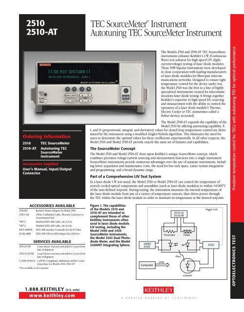
The Models 2510 and 2510-AT <strong>TEC</strong> <strong>SourceMeter</strong><br />
instruments enhance <strong>Keithley</strong>’s CW (Continuous<br />
Wave) test solution for high speed LIV (lightcurrent-voltage)<br />
testing of laser diode modules.<br />
These 50W bipolar instruments were developed<br />
in close cooperation with leading manufacturers<br />
of laser diode modules for fiberoptic telecommunications<br />
networks. Designed to ensure tight<br />
temperature control for the device under test,<br />
the Model 2510 was the first in a line of highly<br />
specialized instruments created for telecommunications<br />
laser diode testing. It brings together<br />
<strong>Keithley</strong>’s expertise in high speed DC sourcing<br />
and measurement with the ability to control the<br />
operation of a laser diode module’s Thermo-<br />
Electric Cooler or <strong>TEC</strong> (sometimes called a<br />
Peltier device) accurately.<br />
The Model 2510-AT expands the capability of the<br />
Model 2510 by offering autotuning capability. P,<br />
I, and D (proportional, integral, and derivative) values for closed loop temperature control are determined<br />
by the instrument using a modified Zeigler-Nichols algorithm. This eliminates the need for<br />
users to determine the optimal values for these coefficients experimentally. In all other respects, the<br />
Model 2510 and Model 2510-AT provide exactly the same set of features and capabilities.<br />
The <strong>SourceMeter</strong> Concept<br />
The Model 2510 and Model 2510-AT draw upon <strong>Keithley</strong>’s unique Source Meter concept, which<br />
combines precision voltage/current sourcing and measurement functions into a single instrument.<br />
<strong>SourceMeter</strong> instruments provide numerous advantages over the use of separate instruments, including<br />
lower acquisition and maintenance costs, the need for less rack space, easier system integration<br />
and programming, and a broad dynamic range.<br />
Part of a Comprehensive LIV Test System<br />
In a laser diode CW test stand, the Model 2510 or Model 2510-AT can control the temperature of<br />
actively cooled optical components and assemblies (such as laser diode modules) to within ±0.005°C<br />
of the user-defined setpoint. During testing, the instrument measures the internal temperature of<br />
the laser diode module from any of a variety of temperature sensors, then drives power through<br />
the <strong>TEC</strong> within the laser diode module in order to maintain its temperature at the desired setpoint.<br />
Figure 1. The capabilities<br />
of the Models 2510 and<br />
2510-AT are intended to<br />
complement those of other<br />
<strong>Keithley</strong> instruments often<br />
used in laser diode module<br />
LIV testing, including the<br />
Model 2400 and 2420<br />
<strong>SourceMeter</strong> instruments,<br />
the Model 2502 Dual Photodiode<br />
Meter, and the Model<br />
2500INT Integrating Sphere.<br />
2400/<br />
2420<br />
Computer<br />
GPIB<br />
2510 or<br />
2510-AT<br />
Thermistor Peltier<br />
Fiber<br />
2500INT<br />
A G R E A T E R M E A S U R E O F C O N F I D E N C E<br />
Trigger Link<br />
2502<br />
Precision temperature control for <strong>TEC</strong>s Side with Text autotuning PID for optimal performance<br />
OPTOELECTRONICS TEST
Precision temperature control for <strong>TEC</strong>s Side with Text autotuning PID for optimal performance<br />
OPTOELECTRONICS TEST<br />
2510<br />
2510-AT<br />
50W <strong>TEC</strong> Controller combined<br />
with DC measurement functions<br />
Fully digital P-I-D control<br />
Autotuning capability for the<br />
thermal control loop (2510-AT)<br />
Designed to control temperature<br />
during laser diode module testing<br />
Wide temperature setpoint range<br />
(–50°C to +225°C) and high<br />
setpoint resolution (±0.001°C)<br />
and stability (±0.005°C)<br />
Compatible with a variety of<br />
temperature sensor inputs—<br />
thermistors, RTDs, and IC sensors<br />
Maintains constant temperature,<br />
current, voltage, and sensor<br />
resistance<br />
AC Ohms measurement function<br />
verifies integrity of <strong>TEC</strong><br />
Measures and displays <strong>TEC</strong><br />
parameters during the control<br />
cycle<br />
4-wire open/short lead detection<br />
for thermal feedback element<br />
IEEE-488 and RS-232 interfaces<br />
Compact, half-rack design<br />
APPLICATIONS<br />
Control and production testing<br />
of thermoelectric coolers (Peltier<br />
devices) in:<br />
Laser diode modules<br />
IR charge-coupled device (CCD)<br />
arrays and charge- injection<br />
devices (CID)<br />
Cooled photodetectors<br />
Thermal-optic switches<br />
Temperature controlled fixtures<br />
1.888.KEITHLEY (U.S. only)<br />
www.keithley.com<br />
<strong>TEC</strong> <strong>SourceMeter</strong> Instrument<br />
Autotuning <strong>TEC</strong> <strong>SourceMeter</strong> Instrument<br />
T MAX<br />
T START<br />
Temp<br />
Figure 2.<br />
Temp (°C)<br />
27<br />
26<br />
25<br />
24<br />
Figure 3.<br />
Temp (°C)<br />
Figure 4.<br />
Max.<br />
Initial<br />
Slope<br />
L<br />
t L<br />
T S<br />
t e<br />
63%<br />
Laser Diode <strong>TEC</strong> Minimum Overshoot<br />
23<br />
0 5 10 15 20 25<br />
27<br />
26<br />
25<br />
24<br />
Time (s)<br />
Laser Diode <strong>TEC</strong> Minimum Settling Time<br />
23<br />
0 5 10 15 20 25<br />
Time (s)<br />
Active temperature control is very<br />
important due to the sensitivity<br />
of laser diodes to temperature<br />
changes. If the temperature varies,<br />
the laser diode’s dominant<br />
output wavelength may change,<br />
leading to signal overlap and<br />
crosstalk problems.<br />
Autotuning Function<br />
Time<br />
The Model 2510-AT Autotuning<br />
<strong>TEC</strong> <strong>SourceMeter</strong> instrument<br />
offers manu facturers the ability<br />
to automatically tune the temperature<br />
control loop required for CW testing of<br />
optoelectronic components such as laser diode<br />
modules and thermo-optic switches. This capability<br />
eliminates the need for time-consuming<br />
experimentation to determine the optimal P-I-D<br />
coefficient values.<br />
The Model 2510-AT’s P-I-D Auto-Tune software<br />
employs a modified Ziegler-Nichols algorithm to<br />
determine the coefficients used to control the<br />
P-I-D loop. This algorithm ensures that the final<br />
settling perturbations are damped by 25% each<br />
cycle of the oscillation. The autotuning process<br />
begins with applying a voltage step input to the<br />
system being tuned (in open loop mode) and<br />
measuring several parameters of the system’s<br />
response to this voltage step function. The<br />
system’s response to the step function is illustrated<br />
in Figure 2. The lag time of the system<br />
response, the maximum initial slope, and the<br />
TAU [63% (1/e)] response time are measured,<br />
then used to generate the Kp (proportional gain<br />
constant), Ki (integral gain constant), and Kd<br />
(derivative gain constant) coefficients.<br />
The autotuning function offers users a choice of<br />
a minimum settling time mode or a minimum<br />
overshoot mode, which provides the Model<br />
2510-AT with the flexibility to be used with a<br />
variety of load types and devices. For example,<br />
when controlling a large area <strong>TEC</strong> in a test fixture<br />
optimized for P, I, and D values, minimum<br />
overshoot protects the devices in the fixture<br />
from damage (Figure 3). For temperature<br />
setpoints that do not approach the maximum<br />
specified temperature for the device under test,<br />
the minimum settling time mode can be used to<br />
speed up the autotuning function (Figure 4).<br />
50W Output<br />
As the complexity of today’s laser diode modules<br />
increases, higher power levels are needed in<br />
temperature controllers to address the module’s<br />
cooling needs during production test. The 50W<br />
A G R E A T E R M E A S U R E O F C O N F I D E N C E
2510<br />
2510-AT<br />
(5A @ 10V) output allows for higher testing speeds and a wider temperature<br />
setpoint range than other, lower-power solutions.<br />
High Stability P-I-D Control<br />
When compared with other <strong>TEC</strong> controllers, which use less sophisticated<br />
P-I (proportional-integral) loops and hardware control mechanisms, this<br />
instrument’s software-based, fully digital P-I-D control provides greater<br />
temperature stability and can be easily upgraded with a simple firmware<br />
change. The resulting temperature stability (±0.005°C short term,<br />
±0.01°C long term) allows for very fine control over the output wavelength<br />
and optical power of the laser diode module during production testing<br />
of DC characteristics. This improved stability gives users higher confidence<br />
in measured values, especially for components or sub-assemblies<br />
in wavelength multiplexed networks. The derivative component of the<br />
instrument’s P-I-D control also reduces the required waiting time between<br />
making measurements at various temperature setpoints. The temperature<br />
setpoint range of –50°C to +225°C covers most of the test requirements for<br />
production testing of cooled optical components and sub-assemblies, with<br />
a resolution of ±0.001°C.<br />
Before the introduction of the Model 2510-AT, configuring test systems for<br />
new module designs and fixtures required the user to determine the best<br />
combination of P, I, and D coefficients through trial-and-error experimentation.<br />
The Model 2510-AT’s autotuning function uses the modified Zeigler-<br />
Nichols algorithm to determine the optimal P, I, and D values automatically.<br />
Adaptable to Evolving DUT Requirements<br />
The Model 2510 and Model 2510-AT are well suited for testing a wide range<br />
of laser diode modules because they are compatible with the types of<br />
temperature sensors most commonly used in these modules. In addition<br />
to 100Ω, 1kΩ, 10kΩ, and 100kΩ thermistors, they can handle inputs<br />
from 100Ω or 1kΩ RTDs, and a variety of solid-state temperature sensors.<br />
This input flexibility ensures their adaptability as the modules being tested<br />
evolve over time.<br />
Programmable Setpoints and Limits<br />
Users can assign temperature, current, voltage, and thermistor resistance<br />
setpoints. The thermistor resistance setpoint feature allows higher correlation<br />
of test results with actual performance in the field for laser diode<br />
modules because reference resistors are used to control the temperature<br />
of the module. Programmable power, current, and temperature limits offer<br />
maximum protection against damage to the device under test.<br />
Accurate Real-Time Measurements<br />
Both models can perform real-time measurements on the <strong>TEC</strong>, including<br />
<strong>TEC</strong> current, voltage drop, power dissipation, and resistance, providing<br />
valuable information on the operation of the thermal control system.<br />
Peltier (<strong>TEC</strong>) Ohms Measurement<br />
<strong>TEC</strong> devices are easily affected by mechanical damage, such as sheer stress<br />
during assembly. The most effective method to test a device for damage<br />
after it has been incorporated into a laser diode module is to perform a<br />
low-level AC (or reversing DC) ohms measurement. If there is a change in<br />
the <strong>TEC</strong>’s resistance value when compared with the manufacturer’s specification,<br />
mechanical damage is indicated. Unlike a standard DC resistance<br />
measurement, where the current passing through the device can produce<br />
device heating and affect the measured resistance, the reversing DC ohms<br />
method does not and allows more accurate measurements.<br />
1.888.KEITHLEY (U.S. only)<br />
www.keithley.com<br />
<strong>TEC</strong> <strong>SourceMeter</strong> Instrument<br />
Autotuning <strong>TEC</strong> <strong>SourceMeter</strong> Instrument<br />
Open/Short Lead Detection<br />
Both models of the instrument use a four-wire measurement method to<br />
detect open/short leads on the temperature sensor before testing. Fourwire<br />
measure ments eliminate lead resistance errors on the measured<br />
value, reducing the possibility of false failures or device damage.<br />
Interface Options<br />
Like all newer <strong>Keithley</strong> instruments, both models of the instrument include<br />
standard IEEE-488 and RS-232 interfaces to speed and simplify system integration<br />
and control.<br />
Optional Resistive Heater Adapter<br />
The Model 2510-RH Resistive<br />
Heater Adapter enables either<br />
model of the instrument to provide<br />
closed loop temperature control<br />
for resistive heater elements, rather<br />
than for <strong>TEC</strong>s. When the adapter is<br />
installed at the instrument’s output<br />
terminal, current flows through the<br />
resistive heater when the P-I-D loop<br />
indicates heating. However, no current<br />
will flow to the resistive heater<br />
when the temperature loop calls<br />
for cooling. The resistive element is<br />
cooled through radiation, conduc- Figure 6. Optional heater adapter<br />
tion, or convection.<br />
°C<br />
0.01<br />
0.005<br />
0<br />
-0.005<br />
-0.01<br />
-0.015<br />
Comparison Data<br />
One Hour Interval<br />
Figure 5. This graph compares the Model 2510/2510-AT’s A/D converter<br />
resolution and temperature stability with that of a leading competitive<br />
instrument. While the competitive instrument uses an analog<br />
proportional-integral (P-I) control loop, it displays information in<br />
digital format through a low-resolution analog-to-digital converter. In<br />
contrast, the Model 2510/2510-AT uses a high-precision digital P-I-D<br />
control loop, which provides greater temperature stability, both over<br />
the short term (±0.005°C) and the long term (±0.01°C).<br />
A G R E A T E R M E A S U R E O F C O N F I D E N C E<br />
2510 Measured<br />
Competitor Measured<br />
Precision temperature control for <strong>TEC</strong>s Side with Text autotuning PID for optimal performance<br />
OPTOELECTRONICS TEST
Model 2510, 2510-AT Side Textspecifications<br />
OPTOELECTRONICS TEST<br />
2510<br />
2510-AT<br />
SPECIFICATIONS<br />
The Models 2510 and 2510-AT <strong>TEC</strong> <strong>SourceMeter</strong> instruments are designed to:<br />
Control the power to the <strong>TEC</strong> to maintain a constant temperature, current, voltage, or thermistor<br />
resistance.<br />
Measure the resistance of the <strong>TEC</strong>.<br />
Provide greater control and flexibility through a software P-I-D loop.<br />
CONTROL SYSTEM SPECIFICATIONS<br />
SET: Constant Peltier Temperature, Constant Peltier Voltage, Constant Peltier Current. Constant<br />
Thermistor Resistance.<br />
CONTROL METHOD: Programmable software PID loop. Proportional, Integral, and Derivative<br />
gains independently program mable.<br />
SETPOINT SHORT TERM STABILITY: ±0.005°C rms 1,6,7 .<br />
SETPOINT LONG TERM STABILITY: ±0.01°C 1,6,8 .<br />
SETPOINT RANGE: –50°C to 225°C.<br />
UPPER TEMPERATURE LIMIT: 250°C max.<br />
LOWER TEMPERATURE LIMIT: –50°C max.<br />
SETPOINT RESOLUTION: ±0.001°C, 0.2A.<br />
13. Default values shown, selectable values of 3µA, 10µA, 33µA, 100µA,<br />
833µA, 2.5mA. Note that temperature control performance will<br />
degrade at lower currents.<br />
14. AC ohms is a dual pulsed meas urement using current reversals available<br />
over bus only.<br />
15. Settable to