Light oil pressure jet burner SL 400/2, SL 410/2, SL 420/2 ... - Intercal
Light oil pressure jet burner SL 400/2, SL 410/2, SL 420/2 ... - Intercal
Light oil pressure jet burner SL 400/2, SL 410/2, SL 420/2 ... - Intercal

Create successful ePaper yourself
Turn your PDF publications into a flip-book with our unique Google optimized e-Paper software.
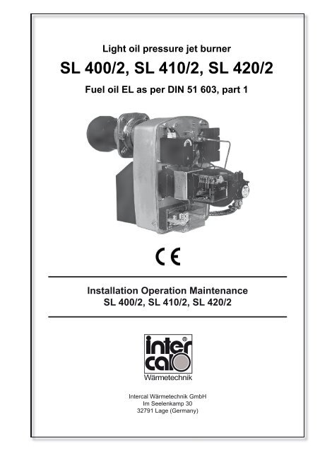
<strong>Light</strong> <strong>oil</strong> <strong>pressure</strong> <strong>jet</strong> <strong>burner</strong><br />
<strong>SL</strong> <strong>400</strong>/2, <strong>SL</strong> <strong>410</strong>/2, <strong>SL</strong> <strong>420</strong>/2<br />
Fuel <strong>oil</strong> EL as per DIN 51 603, part 1<br />
Installation Operation Maintenance<br />
<strong>SL</strong> <strong>400</strong>/2, <strong>SL</strong> <strong>410</strong>/2, <strong>SL</strong> <strong>420</strong>/2<br />
Wärmetechnik<br />
<strong>Intercal</strong> Wärmetechnik GmbH<br />
Im Seelenkamp 30<br />
32791 Lage (Germany)
1 STANDARDS AND REGULATIONS .................................................................... 5<br />
1.1 Standards and regulations .................................................................................... 5<br />
1.2 Exhaust system and effective heat demand ......................................................... 5<br />
1.3 Nozzle selection .................................................................................................... 5<br />
2 GENERAL ............................................................................................................. 6<br />
2.1 Modern concept .................................................................................................... 6<br />
2.2 Two-stage <strong>burner</strong>s <strong>SL</strong> <strong>400</strong>/2 und <strong>SL</strong> <strong>410</strong>/2 ........................................................... 6<br />
2.3 Modern design ...................................................................................................... 6<br />
3 INSTALLATION ..................................................................................................... 7<br />
3.1 Simple installation ................................................................................................. 7<br />
3.2 Instructions for using the <strong>burner</strong> ........................................................................... 7<br />
4 OPERATION ......................................................................................................... 8<br />
4.1 Operation and adjusting ........................................................................................ 8<br />
4.2 Air intake nozzle .................................................................................................... 8<br />
4.3 Adjusting the <strong>oil</strong> <strong>pressure</strong>s <strong>SL</strong> <strong>400</strong>/2 to <strong>SL</strong> <strong>410</strong>/2 .................................................. 9<br />
4.4 Adjustment dimensions .......................................................................................... 10<br />
4.5 Ignition electrode setting ......................................................................................... 10<br />
5 MAINTENANCE ...................................................................................................... 11<br />
5.1 Maintenance and service ........................................................................................ 11<br />
6 TROUBLESHOOTING ............................................................................................12<br />
6.1 Troubleshooting ...................................................................................................... 12<br />
7 TECHNICAL DOCUMENTATION .......................................................................... 14<br />
7.1 Basic settings table and adjustment dimensions <strong>SL</strong> <strong>400</strong>/2 - <strong>SL</strong> <strong>420</strong>/2 ................... 14<br />
7.2 Electrical connection ............................................................................................... 15<br />
7.3 B<strong>oil</strong>er connection .................................................................................................... 15<br />
7.4 Working fi eld ........................................................................................................... 15<br />
7.5 Defi ning the <strong>oil</strong> feed pipe ........................................................................................ 16<br />
7.6 Circuit diagram <strong>SL</strong> <strong>400</strong>/2 ........................................................................................ 17<br />
7.7 Circuit diagram <strong>SL</strong> <strong>410</strong>/2 - <strong>420</strong>/2 ............................................................................ 18<br />
7.8 Explosion drawing <strong>SL</strong> <strong>400</strong>/2.................................................................................... 21<br />
7.9 Key for explosion drawing <strong>SL</strong> <strong>400</strong>/2 ....................................................................... 22<br />
7.10 Explosion drawing <strong>SL</strong> <strong>410</strong>/2 - <strong>SL</strong> <strong>420</strong>/2 .................................................................. 23<br />
7.11 Key for explosion drawing <strong>SL</strong> <strong>410</strong>/2 - <strong>SL</strong> <strong>420</strong>/2 ...................................................... 24<br />
7.12 Burner dimensions .................................................................................................. 25<br />
8 GUARANTEE .......................................................................................................... 26<br />
8.1 Guarantee ............................................................................................................... 26<br />
8.2 Oil tank and <strong>oil</strong> pipes .............................................................................................. 26<br />
8.3 Spare parts ............................................................................................................. 26<br />
Manufacturer‘s certifi cate ................................................................................................... 27<br />
Contens<br />
Installation Operation Maintenance 3<br />
<strong>SL</strong> <strong>400</strong>/2, <strong>SL</strong> <strong>410</strong>/2, <strong>SL</strong> <strong>420</strong>/2
Safety instructions – Please observe!<br />
Please comply with the assembly, operation and maintenance instructions for installing and<br />
adjusting the light <strong>oil</strong> <strong>pressure</strong> <strong>jet</strong> <strong>burner</strong>!<br />
Please read this installation manual carefully before starting installation. We cannot assume any<br />
liability or guarantee for damage caused by failure to comply with this installation manual!<br />
Work which is not carried out properly can cause injury to persons or damage to property!<br />
Work on the heating system Installation, commissioning, maintenance and<br />
servicing work may only be carried out by an authorised<br />
firm of heating contractors.<br />
When working on <strong>burner</strong> and b<strong>oil</strong>er switch off the heating system emergency switch and<br />
secure it to prevent it being switched on again.<br />
shut off the <strong>oil</strong> feed pipe and secure it to prevent it<br />
being opened unintentionally.<br />
This symbol refers to instructions which must be heeded for your own safety<br />
and that of other people,<br />
and to avoid damage to property.<br />
This symbol refers to instructions which must be heeded for the <strong>burner</strong> to<br />
operate safely and function correctly. It also draws attention to statutory<br />
regulations which need to be observed.<br />
<strong>SL</strong> <strong>400</strong>/2, <strong>SL</strong> <strong>410</strong>/2, <strong>SL</strong> <strong>420</strong>/2 4<br />
Installation Operation Maintenance
1.1 Standards and regulations<br />
1. Standards and regulations<br />
The following standards and regulations are to be observed during installa-tion and operation of the <strong>burner</strong>.<br />
HeizAnlV<br />
Heating system ordinance<br />
FeuVo<br />
Firing ordinance of the German federal states<br />
1. BImSchV<br />
First ordinance for implementation of the German Emission Pro-tection Law<br />
VDI 2035<br />
Guidelines for preventing damage from corrosion and scale formation in hot water heating installations<br />
VDE<br />
Regulations and special requirements issued by the energy utility companies<br />
EN 303, Part 1 and Part 2<br />
Heating b<strong>oil</strong>ers with forced draught <strong>burner</strong>s<br />
EN 60335, Part 1<br />
Safety of household and similar electrical appliances<br />
DIN 4705<br />
Calculating the dimensions of chimneys<br />
DIN 4751<br />
Hot water heating installations – safety requirements<br />
DIN 4755<br />
Oil fi ring installations – construction, execution, safety require-ments<br />
DIN EN 267<br />
Automatic forced draught <strong>burner</strong>s for liquid fuels – defi nitions, requirements, construction and testing<br />
DIN 51603, Part 1<br />
Fuel <strong>oil</strong>s extra light<br />
DIN 57116<br />
Electrical equipment of fi ring installations<br />
Please comply with the valid regional building code.<br />
1.2 Exhaust system and effective heat demand<br />
B<strong>oil</strong>er, <strong>burner</strong> and exhaust system (chimney) constitute an operating unit; account must be taken of low exhaust<br />
temperatures when reducing the output.<br />
For exhaust temperatures below 160°C, the system must be designed so as to avoid damage from condensation.<br />
It is advisable to install draught limiters (secondary air systems) to achieve stable combustion values under varying<br />
conditions and to reduce possible humidity in the chimney. These should be in-stalled in the chimney where possible,<br />
to avoid any noises in the fl ue pipe.<br />
1.3 Nozzle selection<br />
Please note that trouble-free and low-pollution combustion can only be achieved with nozzles which are rated to the<br />
<strong>burner</strong>. The nozzles stated in chapter 7.1 are certifi ed for light <strong>oil</strong> <strong>pressure</strong> <strong>jet</strong> <strong>burner</strong> <strong>SL</strong> <strong>400</strong>/2, <strong>SL</strong> <strong>410</strong>/2, <strong>SL</strong> <strong>420</strong>/2<br />
and should be used accordingly.<br />
Installation Operation Maintenance 5<br />
<strong>SL</strong> <strong>400</strong>/2, <strong>SL</strong> <strong>410</strong>/2, <strong>SL</strong> <strong>420</strong>/2
2. General<br />
2.1 Modern concept<br />
The <strong>oil</strong> <strong>burner</strong>s <strong>SL</strong> <strong>400</strong>/2, <strong>SL</strong> <strong>410</strong>/2, <strong>SL</strong> <strong>420</strong>/2 are fully automatic <strong>oil</strong> <strong>jet</strong> <strong>burner</strong>s in monobloc design, made and<br />
tested to DIN EN 267 respectively DIN 4787.<br />
The <strong>burner</strong>s are equipped with automatic <strong>oil</strong> fi ring units for intermittent operation to DIN EN 230 respectively DIN<br />
4787; automatic units for continuous operation are available on request.<br />
The two-stage <strong>burner</strong>s of this series consist of over<strong>pressure</strong> <strong>burner</strong>s with very high fan pressing and steep characteristic<br />
curve. Together with the variable adjustment of the air intake nozzle, these features mean that these<br />
<strong>burner</strong>s are ideal equally for modern U-fi red heavy-duty b<strong>oil</strong>ers or for older natural draft b<strong>oil</strong>ers.<br />
Advantages of the modern design: Load stages 1 and 2 are achieved with only one <strong>oil</strong> nozzle and two different <strong>oil</strong><br />
quanti-ties. Nozzle and baffl e plate are fi tted symmetrically in every operating state.<br />
The performance spread of 70:100 guarantees adequate graduation of the two load stages and also safeguards<br />
an ade-quate exhaust temperature even in the small load stage.<br />
2.2 Two-stage <strong>burner</strong>s <strong>SL</strong> <strong>400</strong>/2, <strong>SL</strong> <strong>410</strong>/2, <strong>SL</strong> <strong>420</strong>/2<br />
Housing of die cast light metal, output-dependent <strong>burner</strong> pipes with adjustable nozzle connection, mixing system,<br />
AC motor (<strong>SL</strong> <strong>400</strong>/2) respectively three phase motor with motor contactor (<strong>SL</strong> <strong>410</strong>/2, <strong>SL</strong> <strong>420</strong>/2), ignition transformer,<br />
fan wheel, adjustable air intake nozzle and throttle actuator for twostage operation, <strong>oil</strong> pump with two separately<br />
adjustable <strong>pressure</strong> ranges, solenoid valves, joint nozzle for stage 1 and 2, <strong>oil</strong> hoses, automatic <strong>oil</strong> fi ring unit<br />
with photo resistance, connection plug and fi tting fl ange with fastening screws.<br />
Burner heat tested.<br />
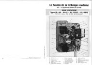
2.3 Modern design<br />
There are constructional advantages in using a modern, symmetrically designed combustion system with only one<br />
nozzle. The symmetrical arrangement of nozzle and mixing system/baffl e plate means that in two-stage operation<br />
with corresponding <strong>oil</strong> <strong>pressure</strong>s and settings of the <strong>oil</strong> throttle, optimum combustion values can be achieved with<br />
almost sootfree operation. Two-stage operation is achieved in <strong>SL</strong> <strong>400</strong>/2, <strong>SL</strong> <strong>410</strong>/2 and <strong>SL</strong> <strong>420</strong>/2 by adjusting the<br />
<strong>oil</strong> <strong>pressure</strong> in the range from 10 to 25 bar. The resulting performance spread of 70:100 allows precise adjustment<br />
to current heating needs, taking account of the tolerable exhaust temperature.<br />
Fig. 1:<br />
<strong>SL</strong> <strong>400</strong>/2, <strong>SL</strong> <strong>410</strong>/2, <strong>SL</strong> <strong>420</strong>/2 6<br />
Installation Operation Maintenance
3.1 Simple installation<br />
3. Installation<br />
The clear arrangement of all parts and complete equipment with output-related nozzles and <strong>oil</strong> hoses makes it<br />
easy for the engineer to install. In the individual <strong>burner</strong> sizes, the <strong>burner</strong> output can be adjusted by changing the<br />
nozzle and correcting the adjustment dimensions. The <strong>burner</strong>s are ready wired to connection plugs. The necessary<br />
<strong>burner</strong> head length can be easily adjusted by a clamping fl ange. All maintenance work can be carried out with a<br />
minimum of tools.<br />
The quality of the equipment, solid workmanship and a comprehensive system of production controls and subsequent<br />
heat testing guarantee a uniformly high production standard.<br />
3.2 Instructions for using the <strong>burner</strong><br />
The <strong>oil</strong>-<strong>burner</strong>s <strong>SL</strong> <strong>400</strong>/2, <strong>SL</strong> <strong>410</strong>/2, <strong>SL</strong> <strong>420</strong>/2 are basically suitable for use in commercially available heating<br />
b<strong>oil</strong>ers (intermittent operation) for heating residential buildings and for service water. Product development and the<br />
test procedures have been geared to the operating conditions of these systems.<br />
The areas of application listed below make particular requirements with special operating conditions for the <strong>burner</strong>,<br />
so that <strong>Intercal</strong> Wärmetechnik reserves the right to issue explicit approval in these cases:<br />
dark radiators<br />
baking ovens<br />
annealing furnaces<br />
drying chambers<br />
industrial applications<br />
In the case of rooms where the air must be expected to be contaminated by halogenated hydrocarbons, e.g. hairdressers,<br />
printers, chemical dry cleaners, laboratories, etc. the <strong>burner</strong>s must only be operated if suitable measures<br />
are taken to ensure that there is an adequate supply of uncontaminated combustion air.<br />
Always consult <strong>Intercal</strong> Wärmetechnik if in any doubt.<br />
The <strong>burner</strong>s must not be operated in rooms with high dust levels or high humidity (e.g. laundries). The heating<br />
room must be protected from frost and well aired.<br />
Failure to comply with these instructions renders the warranty null and void for any damage resulting from one of<br />
these causes.<br />
Installation Operation Maintenance 7<br />
<strong>SL</strong> <strong>400</strong>/2, <strong>SL</strong> <strong>410</strong>/2, <strong>SL</strong> <strong>420</strong>/2
4. Operation<br />
4.1 Operation and adjusting<br />
Every <strong>burner</strong> is preset and heat tested. The basic setting can be seen in chapter 7.1. The following instructions<br />
should be observed when making adjustments:<br />
Only a qualifi ed engineer may proceed with adjustments and initial commissioning. The <strong>oil</strong> <strong>pressure</strong> is adjusted at<br />
the <strong>oil</strong> pump; see section „adjusting the <strong>oil</strong> <strong>pressure</strong>“.<br />
When adjusting the <strong>burner</strong>, it is advisable to measure the air <strong>pressure</strong> before the baffl e plate (see table values for<br />
air <strong>pressure</strong> in chapter 7.1). The measuring fi tting is located next to the nozzle connection on the fl ange cover.<br />
The combustion air can be adjusted in three ways:<br />
a. Adjusting the air intake nozzle; adjustment according to <strong>burner</strong> output and local conditions:<br />
- position 0 - 5 (0 - 1) for natural draft b<strong>oil</strong>ers<br />
- position 6 - 9,5 (2 - 4) for counter-<strong>pressure</strong> b<strong>oil</strong>ers<br />
b. Adjustment of the baffl e plate in the <strong>burner</strong> pipe (see table basic setting); in this way, the air velocity in the<br />
combustion head and the fl ame form can be adjusted to the combustion chamber conditions.<br />
c. Adjustment of the air throttle for the 1st and 2nd stage via cam switch for stage 1 (blue) and stage 2<br />
(orage); turn to the left to reduce the air fl ow and to the right to increase the air fl ow. Inadequate air fl ow in<br />
stage 1 is changed as follows:<br />
- Adjust the cam switch (blue) upwards (more air)<br />
- Briefl y switch over to stage 2 on b<strong>oil</strong>er thermostat 2. After switching back, the actuator turns back to the<br />
required position.<br />
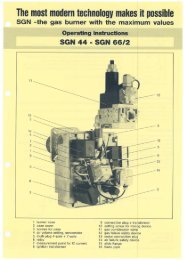
Fig. 2:<br />
4.2 Air intake nozzle<br />
For too much air fl ow in stage 1 or inadequate fl ow in stage 2,<br />
adjust the corresponding cam switch. To reduce too much air fl ow,<br />
adjust the cam switch (orange) accordingly. Close the actuator<br />
briefl y by changing over to the second stage at the controller, or<br />
pulling the green 4-pole connector, and then return to the operating<br />
state.<br />
The long black cam switch can be used to change the switching<br />
point for the 2nd solenoid valve (stage 2). When the <strong>burner</strong> is<br />
switched off normally and because of faults, the air throttle can be<br />
brought to the closed position by using the actuator cam switch<br />
(black, short).<br />
Fig. 3: Adjusting the air intake nozzle:<br />
The intake nozzle can be adjusted after opening the <strong>burner</strong>. For this purpose,<br />
the two screws of the air intake nozzle should only be loosened and then<br />
tightened again after the adjustment has been made.<br />
<strong>SL</strong> <strong>400</strong>/2, <strong>SL</strong> <strong>410</strong>/2, <strong>SL</strong> <strong>420</strong>/2 8<br />
Installation Operation Maintenance
4.3 Adjusting the <strong>oil</strong> <strong>pressure</strong>s<br />
4. Operation<br />
If no <strong>oil</strong> is supplied when <strong>oil</strong> is sucked in for the fi rst time, this must be interrupted after max. 3 minutes to avoid<br />
damage to the pump. The operating condition has been achieved once the <strong>oil</strong> fi lter is fi lled with <strong>oil</strong>.<br />
The <strong>oil</strong> <strong>pressure</strong> is adjusted at the <strong>oil</strong> pump.<br />
The adjustment screws<br />
P1 (upper screw = low <strong>pressure</strong> = stage 1) and<br />
P2 (lower screw = high <strong>pressure</strong> = stage 2).<br />
The adjustment screws are located on the pump cover or on the side of the pump, depending on pump type.<br />
The <strong>pressure</strong> in stage 1 must always be lower than in stage 2.<br />
V = vacuum<br />
P = <strong>oil</strong> <strong>pressure</strong><br />
Never turn the setting screw before venting the pump!<br />
Fig. 5:<br />
Fig. 6:<br />
Installation Operation Maintenance 9<br />
<strong>SL</strong> <strong>400</strong>/2, <strong>SL</strong> <strong>410</strong>/2, <strong>SL</strong> <strong>420</strong>/2<br />
V<br />
P P 2<br />
P 1
4. Operation<br />
4.4 Adjustment dimensions<br />
Fig. 7: Adjustment dimensions <strong>SL</strong> <strong>400</strong>/2<br />
4.6 Ignition electrode setting<br />
Fig. 10:<br />
4.5 Adjustment dimensions<br />
Fig. 8: Adjustment dimensions <strong>SL</strong> <strong>410</strong>/2<br />
and <strong>SL</strong> <strong>420</strong>/2<br />
<strong>SL</strong> <strong>400</strong>/2, <strong>SL</strong> <strong>410</strong>/2, <strong>SL</strong> <strong>420</strong>/2 10<br />
Installation Operation Maintenance
5.1 Maintenance and service<br />
5. Maintenance<br />
On the basis of statutory regulations, it is recommended for <strong>oil</strong> fi ring systems to be serviced by a qualifi ed engineer<br />
every twelve months. The <strong>burner</strong> settings and functions must be checked, the <strong>burner</strong> cleaned (fan wheel,<br />
mixing system, ignition system) and the nozzle replaced if necessary.<br />
The <strong>oil</strong> hoses should be checked every year and replaced after 5 years.<br />
In order to carry out maintenance work, the housing cover with the function parts can be separated from the <strong>burner</strong><br />
housing by loosening the attachment screws, pulled out and hung in the service position.<br />
Check screwed unions for leaks during annual maintenance. Replace defect or worn seals.<br />
Fig. 11:<br />
Burner in service position<br />
Installation Operation Maintenance 11<br />
<strong>SL</strong> <strong>400</strong>/2, <strong>SL</strong> <strong>410</strong>/2, <strong>SL</strong> <strong>420</strong>/2
6. Troubleshooting<br />
6.1 Troubleshooting<br />
Check general operating status. Are the stated values maintained?<br />
Fault Cause Remedy<br />
Burner does not work Power failure.<br />
Control chain closed?<br />
Burner starts,<br />
<strong>oil</strong> sight glass at <strong>oil</strong><br />
fi lter remains empty<br />
Burner starts,<br />
<strong>oil</strong> level glass fi lled,<br />
ignition stays off,<br />
system shuts down<br />
Automatic fi ring unit defect.<br />
Plug not removed or incorrect connection<br />
during initial commissioning.<br />
Oil pipe was not fi lled during initial<br />
commissioning; it takes several minutes for<br />
the <strong>oil</strong> to be sucked in.<br />
Fuel <strong>oil</strong> in <strong>oil</strong> tank? Suction pipe valve<br />
open?<br />
Wrong direction of fl ow at check valve.<br />
Oil pump not working.<br />
Coupling between motor and <strong>oil</strong> pump<br />
defect<br />
Leaking suction pipe or vacuum too high.<br />
Oil pipe squashed.<br />
Separate valve, e.g. valve outside tank<br />
closed<br />
Ignition transformer or cable not OK.<br />
Extremely worn ignition electrodes or<br />
damaged insulators.<br />
Incorrect setting of ignition electrodes.<br />
Incidence of secondary light at fl ame<br />
monitor<br />
Firing sequence controller damaged.<br />
Check main switch and fuses, operating<br />
switch, STB, TR<br />
Check <strong>burner</strong> motor and capacitor (<strong>SL</strong><br />
<strong>400</strong>/2), replace if necessary.<br />
Replace fi ring sequence controller<br />
Check <strong>oil</strong> hoses in case bung not removed,<br />
check that correctly connected<br />
Fill <strong>oil</strong> pipe before initial commissioning.<br />
Do not let the <strong>oil</strong> pump run for longer<br />
than 3 minutes without <strong>oil</strong>!<br />
Check <strong>oil</strong> tank display and valve in suction<br />
pipe.<br />
Check direction of fl ow at check valve.<br />
Check and possibly replace electric<br />
connection.<br />
Replace coupling.<br />
See rating the <strong>oil</strong> pipe (chapter 7.5)<br />
Check <strong>oil</strong> pipe, replace if necessary.<br />
Open corresponding valve. Check routing<br />
of <strong>oil</strong> pipe.<br />
Replace ignition transformer or cable.<br />
Replace spark electrodes.<br />
Correct setting of ignition electrodes as per<br />
settings.<br />
Prevent incidence of secondary light at<br />
fl ame monitor<br />
Replace fi ring sequence controller<br />
<strong>SL</strong> <strong>400</strong>/2, <strong>SL</strong> <strong>410</strong>/2, <strong>SL</strong> <strong>420</strong>/2 12<br />
Installation Operation Maintenance
Fault Cause Remedy<br />
Burner starts,<br />
spark visible,<br />
fl ame does not ignite<br />
or<br />
<strong>burner</strong> switches<br />
off during ongoing<br />
operation<br />
Burner works,<br />
fl ame monitoring does<br />
not start.<br />
Injection or burning<br />
continues after <strong>burner</strong><br />
has shut down<br />
Oil solenoid does not open.<br />
No passage through <strong>oil</strong> pipe, preheater and<br />
nozzle.<br />
Oil pump delivers no <strong>oil</strong>, <strong>oil</strong> tank empty.<br />
Filter in nozzle clogged.<br />
Suction pipe leaks.<br />
Suction pipe not vented.<br />
Mixing device clogged.<br />
Burner setting not OK.<br />
Flame monitor clogged or defect.<br />
Defect cable connection between fl ame<br />
monitor and automatic fi ring unit.<br />
Firing sequence controller damaged.<br />
Oil pipes inadequately vented.<br />
Leak in <strong>oil</strong> suction pipe with intake of air.<br />
Solenoid does not close properly.<br />
6. Troubleshooting<br />
Replace <strong>oil</strong> solenoid c<strong>oil</strong>, check electrical<br />
connection cable.<br />
Check that <strong>oil</strong> pipe, pre-heater and nozzle<br />
are not blocked, replace if necessary<br />
Check <strong>oil</strong> pump and <strong>oil</strong> tank display,<br />
replace respectively top up tank if<br />
necessary.<br />
Replace nozzle.<br />
Check suction pipe, tighten unions<br />
Vent suction pipes at pump <strong>pressure</strong> gauge<br />
connection.<br />
Check and possibly clean mixing device.<br />
Check and possibly correct <strong>burner</strong> setting.<br />
Check resp. clean fl ame monitor. Measure<br />
sensor current.<br />
Replace cable connection resp. fl ame<br />
monitor.<br />
Replace fi ring sequence controller<br />
Remedy by venting<br />
Check all sealing points in the <strong>oil</strong> piping.<br />
Solenoid defect.<br />
Installation Operation Maintenance 13<br />
<strong>SL</strong> <strong>400</strong>/2, <strong>SL</strong> <strong>410</strong>/2, <strong>SL</strong> <strong>420</strong>/2
7. Technical documentation<br />
7.1 Basic settings table and adjustment dimensions<br />
Burner type<br />
<strong>SL</strong> <strong>400</strong>/2<br />
<strong>SL</strong> <strong>410</strong>/2<br />
<strong>SL</strong> <strong>420</strong>/2<br />
Suitable for<br />
b<strong>oil</strong>er output<br />
kW<br />
260 - 290<br />
290 - 315<br />
315 - 360<br />
360 - <strong>420</strong><br />
<strong>420</strong> - 500<br />
450 - 520<br />
520 - 580<br />
570 - 630<br />
600 - 670<br />
Nozzle / Make / Type<br />
USG<br />
Steinen 4,50 60°S<br />
Steinen 5,00 60°S<br />
Steinen 5,50 60°S<br />
Steinen 6,50 60°S<br />
Steinen 7,50 60°S<br />
Steinen 8,00 60°S<br />
Steinen 9,00 60°S<br />
Steinen 10,00 60°S<br />
Steinen 11,00 60°S<br />
Size A<br />
mm<br />
21<br />
21<br />
20<br />
20<br />
20<br />
20<br />
20<br />
20<br />
20<br />
<strong>SL</strong> <strong>400</strong>/2, <strong>SL</strong> <strong>410</strong>/2, <strong>SL</strong> <strong>420</strong>/2 14<br />
Installation Operation Maintenance<br />
Size<br />
B<br />
mm<br />
62<br />
62<br />
125<br />
120<br />
115<br />
110<br />
100<br />
95<br />
90<br />
Size<br />
D<br />
mm<br />
114<br />
114<br />
130<br />
130<br />
130<br />
130<br />
134<br />
134<br />
134<br />
Air <strong>pressure</strong> Oil <strong>pressure</strong><br />
St. 1<br />
mbar<br />
4,0<br />
5,0<br />
6,8<br />
8,0<br />
8,6<br />
8,8<br />
8,8<br />
8,0<br />
9,0<br />
St. 2<br />
mbar<br />
7,5<br />
8,5<br />
11,5<br />
12,5<br />
13,5<br />
13,5<br />
14,0<br />
13,0<br />
13,0<br />
St. 1<br />
bar<br />
17<br />
17<br />
13<br />
15<br />
14<br />
14<br />
14<br />
13<br />
14<br />
St. 2<br />
bar<br />
27<br />
27<br />
20<br />
23<br />
22<br />
24<br />
26<br />
25<br />
23<br />
Air intake<br />
nozzle<br />
2,2<br />
3,5<br />
4<br />
6<br />
7,5<br />
7,5<br />
7,5<br />
7,5<br />
7,5<br />
Total<br />
weight<br />
kg<br />
45<br />
45<br />
45<br />
45<br />
45<br />
45<br />
45<br />
45<br />
45
7.2 Electrical connection<br />
Burner type<br />
7.4 Working fi eld<br />
Motorvoltage<br />
Motoroutput<br />
Connection value<br />
<strong>SL</strong> <strong>400</strong>/2 230 V WS 50 Hz 0,45 kW 0,7 kW, ca. 3,2 A<br />
<strong>SL</strong> <strong>410</strong>/2 <strong>400</strong> V DS 50 Hz 1,1 kW 1,4 kW, ca. 3,0 A<br />
<strong>SL</strong> <strong>420</strong>/2 <strong>400</strong> V DS 50 Hz 1,1 kW 1,4 kW, ca. 3,0 A<br />
Fig. 14:<br />
7. Technical Dokumentation<br />
7.3 B<strong>oil</strong>er connection<br />
D1 D2 M<br />
150 180 − 205 10<br />
The diagrams shown here indicate approximately the output range of the various sizes as a function of the combustion<br />
chamber resistance during operation. The curves represent maximum values and correspond to the type<br />
sample testing to DIN 4787.<br />
The starting-up resistance of the b<strong>oil</strong>er is of decisive importance for the actually possible <strong>burner</strong> output.<br />
Installation Operation Maintenance 15<br />
<strong>SL</strong> <strong>400</strong>/2, <strong>SL</strong> <strong>410</strong>/2, <strong>SL</strong> <strong>420</strong>/2
7. Technical documentation<br />
7.5 Defi ning the <strong>oil</strong> feed pipe<br />
H = difference in height between suction point (foot valve) and <strong>burner</strong> pump<br />
Positive H value = higher tank<br />
Negative H value = lower tank<br />
L = suction length (2-pipe installation) for pipe inner diameter<br />
di = 8 to di = 16 – indicative values (including 4 elbows, fi lter and non-return valve)<br />
H<br />
(m)<br />
<strong>SL</strong> <strong>400</strong>/2 - <strong>SL</strong> <strong>410</strong>/2 - <strong>SL</strong><strong>420</strong>/2<br />
L (m)<br />
di=8 di=10<br />
4,0 53 100<br />
3,0 47 100<br />
2,0 41 100<br />
1,0 34 88<br />
0,5 31 79<br />
0,0 27 71<br />
-0,5 24 62<br />
-1,0 20 54<br />
-2,0 13 37<br />
-3,0 6 20<br />
<strong>SL</strong> <strong>400</strong>/2, <strong>SL</strong> <strong>410</strong>/2, <strong>SL</strong> <strong>420</strong>/2 16<br />
Installation Operation Maintenance
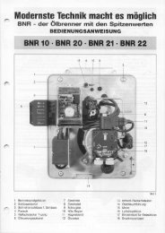
7.6 Circuit diagram <strong>SL</strong> <strong>400</strong>/2<br />
Indication<br />
On-off switch<br />
Pos.<br />
b2<br />
Observe local and VDEregulations.<br />
Safety thermostat b3<br />
On-off thermostat 1 b4<br />
Connections to earth potential<br />
On-off thermostat 2 b5<br />
being executed carefully.<br />
Photo resistor f1<br />
Motor with condenser<br />
Ignition transformer<br />
Servomotor<br />
m1<br />
m2<br />
m3<br />
DKW 972 with MZ 770 for warm<br />
air heater<br />
Solenoid valve 1 s1<br />
Solenoid valve 2 s2<br />
Control device u1<br />
Fig. 15:<br />
7. Technical documentation<br />
<strong>SL</strong> <strong>400</strong>/2, <strong>SL</strong> <strong>410</strong>/2, <strong>SL</strong> <strong>420</strong>/2 17<br />
Installation Operation Maintenance
7. Technical documentation<br />
7.7 Circuit diagram <strong>SL</strong> <strong>410</strong>/2 - <strong>420</strong>/2<br />
Fig. 16:<br />
Installation Operation Maintenance 18<br />
<strong>SL</strong> <strong>400</strong>/2, <strong>SL</strong> <strong>410</strong>/2, <strong>SL</strong> <strong>420</strong>/2
7.8 Explosion drawing <strong>SL</strong> <strong>400</strong>/2<br />
Fig. 18:<br />
7. Technical documentation<br />
Installation 20Operation<br />
Maintenance <strong>SL</strong> <strong>400</strong>/2, <strong>SL</strong> <strong>410</strong>/2, <strong>SL</strong> <strong>420</strong>/2<br />
<strong>SL</strong><strong>400</strong>/2
7. Technical documentation<br />
7.9 Key for explosion drawing <strong>SL</strong> <strong>400</strong>/2<br />
Pos. <strong>SL</strong> <strong>400</strong>/2 Designation (part designation) Part number<br />
1 1 Burner casing<br />
2 1 Housing cover<br />
3 1 Burner pipe DZ 3.0/GZ 3.0<br />
6 1 Baffl e plate with electrode block<br />
11 1 Nozzle 4,50/60 Grd S<br />
11 Nozzle 5,00/60 Grd S<br />
12 1 Nozzle holder with pipe and scale<br />
14 1 Ignition electrode block<br />
15 2 Ignition cable<br />
16 1 Photo resistance. FZ 711S, white<br />
16 1 Photo resistance MZ 770 S<br />
17 1 Servomotor LKS160-52<br />
18 1 Lever for air damper, complete<br />
19 1 Flange cover<br />
20 1 Ignition transformer ZM 20/12-717<br />
21 1 Automatic <strong>oil</strong> fi ring unit TF 802.2<br />
21 1 Automatic <strong>oil</strong> fi ring unit TF 802.1<br />
21 1 Automatic <strong>oil</strong> fi ring unit TF 832.3<br />
22 1 Console for automatic <strong>oil</strong> fi ring unit<br />
23 1 Spring for air damper<br />
24 1 Air throttle axis DZ 3<br />
25 1 Air damper<br />
27 1 Silencer complete<br />
30 1 Counter plug (b<strong>oil</strong>er)<br />
32 1 Plug part, green, complete<br />
33 1 Union Rp 1/8, zyl., 6 mm<br />
34 1 Oil pipe complete DZ 3<br />
35 1 Oil pump AT 2/65<br />
36 2 Double nipple, Rp ¼ x 3/8<br />
37 2 Silver hose NW 8x1500,R 3/8<br />
39 1 Coupling piece 1-surface<br />
40 1 E-motor with condenser, 450 W<br />
41 1 Fan wheel, 220 x 82 mm<br />
42 1 Air intake nozzle<br />
43 1 Burner hood<br />
44 2 Safety cover<br />
45 2 Plug pin<br />
48 1 Burner fastening set<br />
49 1 Burner head seal<br />
50 1 Burner head seal<br />
53 1 Shim lining for <strong>oil</strong> pump<br />
59 1 Solenoid valve, Suntec for pump AS 47 / AT2-3 (1.St.)<br />
59 1 Solenoid valve c<strong>oil</strong>, Suntec for pump AS 47<br />
60 4 Hexagon nut, M8<br />
<strong>SL</strong> <strong>400</strong>/2, <strong>SL</strong> <strong>410</strong>/2, <strong>SL</strong> <strong>420</strong>/2 21<br />
Installation Operation Maintenance
7.10 Explosion drawing <strong>SL</strong> <strong>410</strong>/2 - <strong>SL</strong> <strong>420</strong>/2<br />
Fig. 19:<br />
7. Technical documentation<br />
<strong>SL</strong> <strong>400</strong>/2, <strong>SL</strong> <strong>410</strong>/2, <strong>SL</strong> <strong>420</strong>/2 22<br />
Installation Operation Maintenance<br />
<strong>SL</strong> <strong>410</strong>/2 –<br />
<strong>SL</strong> <strong>420</strong>/2
7. Technical documentation<br />
7.11 Key for explosion drawing <strong>SL</strong> <strong>410</strong>/2 - <strong>SL</strong> <strong>420</strong>/2<br />
Pos. <strong>SL</strong> <strong>410</strong>/2 <strong>SL</strong> <strong>420</strong>/2 Designation (part designation) Part number<br />
1 1 1 Burner casing<br />
2 1 1 Housing cover<br />
3 1 1 Burner pipe with head<br />
6 1 1 Baffl e plate with electrode block<br />
6 Baffl e plate D=134, DZ3.2 -3240<br />
10 Air conductance device 15Grd<br />
11 1 Nozzle 5,50/60 Grd S<br />
11 1 Nozzle 6,50/60 Grd S<br />
11 1 Nozzle 7,50/60 Grd S<br />
11 1 Nozzle 8,00/60 Grd S<br />
11 1 Nozzle 9,00/60 Grd S<br />
11 1 Nozzle 10,00/60 Grd S<br />
11 1 Nozzle 11,00/60 Grd S<br />
12 1 1 Nozzle holder with pipe and fl ange<br />
14 1 1 Ignition electrode block<br />
15 2 2 Ignition cable<br />
16 1 1 Photo resistance. FZ 711S, white<br />
17 1 1 Servomotor LKS160-52<br />
18 1 1 Lever for air damper, complete<br />
20 1 1 Ignition transformer ZM 20/12-717<br />
21 1 1 Automatic <strong>oil</strong> fi ring unit TMO 720-4<br />
22 1 1 Console for automatic <strong>oil</strong> fi ring unit<br />
23 1 1 Spring for air damper<br />
24 1 1 Air throttle axis DZ 3<br />
25 Air damper<br />
25 1 1 Air damper<br />
27 Silencer<br />
27 1 1 Silencer complete<br />
29 1 1 Lining part, brown/black, complete<br />
30 1 1 Counter plug (b<strong>oil</strong>er)<br />
31 1 1 Lining part, green, complete<br />
32 1 1 Plug part, green, complete<br />
33 1 1 Union Rp 1/8, zyl., 6 mm<br />
34 1 1 Oil pipe complete DZ 3<br />
35 1 1 Oil pump AT 2/75C<br />
36 2 2 Double nipple, Rp ¼ x 3/8<br />
37 2 2 Silver hose NW 8x1500,R 3/8<br />
38 2 2 Sealing rig 13 x 18; Cu<br />
39 1 1 Coupling piece 1-surface<br />
40 1 1 E-Motor, 1,1 kW<br />
41 1 1 Fan wheel, 220 x 82 mm<br />
42 1 1 Air intake nozzle<br />
43 Burner hood with push button<br />
43 Spacer for hood DZ 3<br />
Installation Operation Maintenance 23<br />
<strong>SL</strong> <strong>400</strong>/2, <strong>SL</strong> <strong>410</strong>/2, <strong>SL</strong> <strong>420</strong>/2
Pos. <strong>SL</strong> <strong>410</strong>/2 <strong>SL</strong> <strong>420</strong>/2 Designation (part designation) Part number<br />
43 Push button<br />
43 1 1 Burner hood<br />
44 2 2 Safety cover<br />
45 2 2 Plug pin<br />
48 1 1 Burner fastening set<br />
49 Burner head seal<br />
49 1 1 Burner head seal<br />
50 Burner head<br />
50 1 1 Burner head seal<br />
53 1 1 Shim lining for <strong>oil</strong> pump<br />
55 1 1 Power contactor 3TF2001-OAL2<br />
55 1 1 Power contactor 3RT1016-1AP02 [ab BJ 2003]<br />
56 1 1 Bimetal relay 3UA7021-1E<br />
57 1 1 Lining part, black, complete<br />
58 1 1 Connector part, black, complete<br />
59 1 1 Solenoid valve, Suntec for pump AS 47 / AT2-3 (1.St.)<br />
59 1 1 Solenoid valve c<strong>oil</strong>, Suntec for pump AS 47<br />
61 1 1 Solenoid valve SV 01<br />
62 4 4 Threaded pin, M6x25<br />
63 4 4 Hexagon nut, M8<br />
7. Technical documentation<br />
<strong>SL</strong> <strong>400</strong>/2, <strong>SL</strong> <strong>410</strong>/2, <strong>SL</strong> <strong>420</strong>/2 24<br />
Installation Operation Maintenance
7. Technical documentation<br />
7.12 Burner dimensions<br />
Fig. 20:<br />
Burner<br />
type<br />
<strong>SL</strong> <strong>400</strong>/2<br />
<strong>SL</strong> <strong>410</strong>/2<br />
<strong>SL</strong> <strong>420</strong>/2<br />
Dimension<br />
L1<br />
approx.<br />
200<br />
265<br />
265<br />
Dimension<br />
L2<br />
approx.<br />
130<br />
130<br />
130<br />
Dimension<br />
L3<br />
approx.<br />
830<br />
850<br />
850<br />
Dimension<br />
D1<br />
ø<br />
140<br />
140<br />
140<br />
Dimension<br />
D2<br />
ø<br />
Dimension<br />
H1<br />
Dimension<br />
H2<br />
Dimension<br />
B<br />
<strong>SL</strong> <strong>400</strong>/2, <strong>SL</strong> <strong>410</strong>/2, <strong>SL</strong> <strong>420</strong>/2 25<br />
Installation Operation Maintenance<br />
140<br />
175<br />
175<br />
490<br />
490<br />
490<br />
380<br />
380<br />
380<br />
386<br />
386<br />
386
8.1 Guarantee<br />
8. Guarantee<br />
The <strong>burner</strong> by <strong>Intercal</strong> functions perfectly when installed and operated correctly and when using fuel <strong>oil</strong> EL as per<br />
DIN 51 603, Part 1.<br />
The guarantee is valid for 24 months after initial Operation but maximum 27 months after the date of dispatch and<br />
is restricted to the replacement of defect parts.<br />
For details please consult the <strong>burner</strong> card.<br />
8.2 Oil tank and <strong>oil</strong> pipes<br />
When fi lling the tank, switch the <strong>burner</strong> off and leave off subsequently for 3 hours so that suspended particles can<br />
settle.<br />
Defl agration can be caused by the formation of air bubbles as a result of leaky <strong>oil</strong> pipes and an empty tank.<br />
Do not tolerate any <strong>oil</strong> leaks!<br />
Fire risk!<br />
8.3 Spare parts<br />
Only use original spare parts when replacing parts. Some components, e.g. fl ame monitor, <strong>oil</strong> pump, pre-heater,<br />
are specially designed and manufactured these <strong>burner</strong>s.<br />
Please always state the <strong>burner</strong> number when ordering spare parts.<br />
All dimensions in mm.<br />
Subject to technical modifi cations and changes in components.<br />
Installation Operation Maintenance 26<br />
<strong>SL</strong> <strong>400</strong>/2, <strong>SL</strong> <strong>410</strong>/2, <strong>SL</strong> <strong>420</strong>/2
Manufacturer‘s certifi cate<br />
Manufacturer‘s certifi cate<br />
Wärmetechnik GmbH ▫ Im Seelenkamp 30 ▫ D-32791 Lage<br />
Telefon 0049 (0)5232 6002-0 ▫ Fax 0049 (0)5232 6002-18 ▫ info@intercal.de ▫ www.intercal.de<br />
Umsatzsteuer Ident-Nummer (USt-Id. Nr.): DE 811155318 ▫ Steuer-Nummer: 43 801 86006 Wärmetechnik<br />
Herstellerbescheinigung (§ 7 (2) 1.BImSchV)<br />
Lage, 10.01.2008<br />
Die Firma <strong>Intercal</strong> Wärmetechnik GmbH bescheinigt hiermit, dass der nachstehend aufgeführte Öl-/Gas-Spezialheizkessel<br />
Produkt Ölbrenner<br />
Handelsbezeichnung Leichtöl- Druckzerstäuber<br />
Typ / Baumuster-Nr. <strong>SL</strong><strong>400</strong>/2 - <strong>SL</strong><strong>410</strong>/2 - <strong>SL</strong><strong>420</strong>/2 / 5G852/02<br />
(MHG Heiztechnik DZ 3.0, DZ 3.1, DZ 3.2)<br />
Prüfnormen DIN EN 267<br />
Prüfstelle TÜV Hannover / Sachen-Anhalt e.V.<br />
Diese Produkte erfüllen die Anforderungen der aufgeführten Richtlinien und Normen und stimmen mit dem bei der obigen Prüfstelle<br />
geprüften Baumuster überein. Mit dieser Erklärung ist jedoch keine Zusicherung von Eigenschaften verbunden.<br />
Außerdem werden mit diesen Brennern ab der Leistung 120 kW die Anforderungen der 1.BImSchV erfüllt.<br />
Die oben bezeichneten Ölbrenner sind ausschließlich zum Einbau in den Kessel bestimmt, die ebenfalls nach entsprechnden<br />
Richtlinien und Normen zugelassen sind.<br />
Von dem Anlagenersteller ist zu gewährleisten, dass alle für das Zusammenwirken von Anlagenteilen gültigen Vorschriften beachtet<br />
werden.<br />
M. Niedermayer i. A. S. Raasch<br />
Geschäftsführer Technik<br />
Konformitätserklärung Lage, 10.01.2008<br />
Die Firma <strong>Intercal</strong> Wärmetechnik GmbH bescheinigt hiermit,<br />
dass die nachstehend aufgeführten Ölbrenner:<br />
Produkt Ölbrenner<br />
Handelsbezeichnung Leichtöl- Druckzerstäuber<br />
Typ <strong>SL</strong><strong>400</strong>/2 - <strong>SL</strong><strong>410</strong>/2 - <strong>SL</strong><strong>420</strong>/2<br />
unter Berücksichtigung folgender Normen und Richtlinien hergestellt wurde:<br />
Niederspannungsrichtlinie 73/23 EWG - 01.1973<br />
EMV - Richtlinie 89/337 EWG - 05.1989<br />
Maschienenrichtlinie 98/37/EG - 22.06.1998<br />
unter Bezug auf die Ölbrenner-Norm DIN EN 267<br />
M. Niedermayer i. A. S. Raasch<br />
Geschäftsführer Technik<br />
<strong>SL</strong> <strong>400</strong>/2, <strong>SL</strong> <strong>410</strong>/2, <strong>SL</strong> <strong>420</strong>/2 27<br />
Installation Operation Maintenance
-GER-<br />
<strong>SL</strong><strong>420</strong>/2 <strong>SL</strong><strong>410</strong>/2, <strong>SL</strong><strong>400</strong>/2, Maintenance Operation<br />
<strong>Intercal</strong> Wärmetechnik GmbH<br />
Im Seelenkamp 30<br />
D-32791 Lage<br />
Tel.: +49 (0)5232-60 02-0<br />
Installation<br />
Fax: +49 (0)5232-60 02-18<br />
info@intercal.de<br />
2009 /<br />
Wärmetechnik www.intercal.de<br />
01<br />
subject to technical modifications and falsities