GRABBER® Screws ICC Evaluation Report - Grabber Construction ...
GRABBER® Screws ICC Evaluation Report - Grabber Construction ...
GRABBER® Screws ICC Evaluation Report - Grabber Construction ...

You also want an ePaper? Increase the reach of your titles
YUMPU automatically turns print PDFs into web optimized ePapers that Google loves.
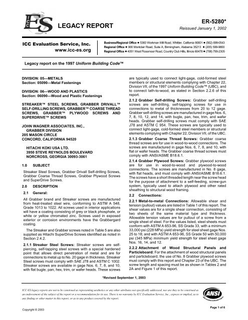
LEGACY REPORT<br />
<strong>ICC</strong> <strong>Evaluation</strong> Service, Inc.<br />
www.icc-es.org<br />
Legacy report on the 1997 Uniform Building Code<br />
DIVISION: 05—METALS<br />
Section: 05090—Metal Fastenings<br />
DIVISION: 06—WOOD AND PLASTICS<br />
Section: 06090—Wood and Plastic Fastenings<br />
STREAKER STEEL SCREWS, GRABBER DRIVALL<br />
SELF-DRILLING SCREWS, GRABBER COARSE THREAD<br />
SCREWS, GRABBER PLYWOOD SCREWS AND<br />
SUPERDRIVE SCREWS<br />
JOHN WAGNER ASSOCIATES, INC.,<br />
GRABBER DIVISION<br />
205 MASON CIRCLE<br />
CONCORD, CALIFORNIA 94520<br />
HITACHI KOKI USA LTD.<br />
3950 STEVE REYNOLDS BOULEVARD<br />
NORCROSS, GEORGIA 30093-3061<br />
1.0 SUBJECT<br />
Streaker Steel <strong>Screws</strong>, <strong>Grabber</strong> Drivall Self-drilling <strong>Screws</strong>,<br />
<strong>Grabber</strong> Coarse Thread <strong>Screws</strong>, <strong>Grabber</strong> Plywood <strong>Screws</strong><br />
and SuperDrive <strong>Screws</strong>.<br />
2.0 DESCRIPTION<br />
2.1 General:<br />
All <strong>Grabber</strong> brand and Streaker screws are manufactured<br />
from heat-treated steel wire, conforming to ASTM A 548,<br />
Grade 1013 to 1022. All screws used in interior applications<br />
will have a coating consisting of grey or black phosphate, or<br />
white or yellow chromated zinc. <strong>Screws</strong> used in exposed<br />
exterior or corrosion environments have the <strong>Grabber</strong>gard<br />
coating.<br />
The Streaker and <strong>Grabber</strong> screws noted in Table 5 are also<br />
supplied as Hitachi SuperDrive <strong>Screws</strong> identified as noted in<br />
Section 2.4.2.<br />
2.1.1 Streaker Steel <strong>Screws</strong>: Streaker screws are selfpiercing,<br />
self-tapping steel screws with a special hardened<br />
point that allows direct penetration of metal and are for<br />
connections to metal up to No. 20 gage in thickness. Streaker<br />
Steel screws must comply with SAE J78 and ASTM C 1002.<br />
Streaker screws are available in gage Nos. 6, 7, 8, and 10,<br />
with flat bugle, pan, hex, trim, or wafer heads. These screws<br />
Copyright © 2003<br />
ER-5280*<br />
Reissued January 1, 2002<br />
Business/Regional Office # 5360 Workman Mill Road, Whittier, California 90601 # (562) 699-0543<br />
Regional Office # 900 Montclair Road, Suite A, Birmingham, Alabama 35213 # (205) 599-9800<br />
Regional Office # 4051 West Flossmoor Road, Country Club Hills, Illinois 60478 # (708) 799-2305<br />
*Revised September 1, 2003<br />
are typically used to connect light-gage, cold-formed steel<br />
members or structural elements complying with Chapter 22,<br />
Division VII, of the 1997 Uniform Building Code (UBC), and<br />
to connect lath-to-wood, as stated in Section 2.2.6 of this<br />
report.<br />
2.1.2 <strong>Grabber</strong> Self-drilling <strong>Screws</strong>: <strong>Grabber</strong> self-drilling<br />
screws are self-drilling, self-tapping screws for use in<br />
connections to metal of thicknesses from 20 to 12 gage.<br />
<strong>Grabber</strong> self-drilling screws are manufactured in gage Nos. 6,<br />
7, 8, 10, 12, and 14, with bugle, pan, hex, trim, and wafer<br />
heads. <strong>Grabber</strong> self-drilling screws must comply with SAE<br />
J78 and ASTM C 954. These screws are typically used to<br />
connect light-gage, cold-formed steel members or structural<br />
elements complying with Chapter 22, Division VII, of the UBC.<br />
2.1.3 <strong>Grabber</strong> Coarse Thread <strong>Screws</strong>: <strong>Grabber</strong> coarse<br />
thread screws are for use in wood-to-wood connections. The<br />
screws are manufactured in gage Nos. 6, 7, 8, and 10, with<br />
flat or wafer heads. The <strong>Grabber</strong> coarse thread screws must<br />
comply with ANSI/ASME B18.6.1.<br />
2.1.4 <strong>Grabber</strong> Plywood <strong>Screws</strong>: <strong>Grabber</strong> plywood screws<br />
are for use in wood-to-wood and plywood-to-wood<br />
connections. The screws are manufactured in No. 8 gage,<br />
with flat heads, and must comply with ANSI/ASME B18.6.1.<br />
The screws have a short threaded length near the screw head<br />
for the purpose of attachment to a self-feeding, screw-gun<br />
system, typically used to attach plywood and other rated<br />
sheathing to structural wood framing.<br />
2.2 Connections:<br />
2.2.1 Metal-to-metal Connections: Allowable shear and<br />
tension (pullout) values are listed in Table 1 of this report. The<br />
shear values are for a single shear connection, consisting of<br />
two sheets of the same material type and thickness.<br />
Allowable tension values are for pullout of a screw from a<br />
single sheet of steel. For the values listed, steel sheets must<br />
conform with ASTM A 653-96, SS Grade 33, with a minimum<br />
33,000 psi (228 MPa) yield strength for steel sheet gage Nos.<br />
25 to 18; and with ASTM A 653-96, SS Grade 50 with 50,000<br />
psi (345 MPa) minimum yield strength for steel sheet gage<br />
Nos. 16, 14, and 12.<br />
2.2.2 Attachment of Wood Structural Panels and<br />
Particleboard: For the attachment of wood structural panels<br />
and particleboard, the use of No. 8 <strong>Grabber</strong> plywood screws<br />
must comply with this report and Chapter 23 of the UBC. The<br />
screw length and spacing must be as shown in Tables 2 and<br />
2A and Figure 1 of this report.<br />
<strong>ICC</strong>-ES legacy reports are not to be construed as representing aesthetics or any other attributes not specifically addressed, nor are they to be construed as<br />
an endorsement of the subject of the report or a recommendation for its use. There is no warranty by <strong>ICC</strong> <strong>Evaluation</strong> Service, Inc., express or implied, as to<br />
any finding or other matter in this report, or as to any product covered by the report.<br />
Page 1 of 6
Page 2 of 6 ER-5280<br />
2.2.3 Wood Connections: Lateral design loads must be<br />
determined in accordance with Part XI of the NDS* using a<br />
bending yield strength of 187,400 psi (1292 MPa) for the No.<br />
8 <strong>Grabber</strong> coarse thread or <strong>Grabber</strong> plywood screws.<br />
Withdrawal design loads must be in accordance with Part XI<br />
of the NDS*.<br />
2.2.4 Wood Structural Panel Shear Connections: Use of<br />
No. 8 <strong>Grabber</strong> plywood or coarse thread screws for the<br />
attachment of structural plywood and other rated panels to<br />
structural wood framing must comply with this report and<br />
Chapter 23 of the UBC. The allowable shear values in Table<br />
3 may be used for the design of horizontal diaphragms. The<br />
allowable shear values in Table 4 may be used for the design<br />
of shear walls.<br />
2.2.5 Attachment of Gypsum Wallboard to Wood or Metal<br />
Framing: Attachment of gypsum wallboard to wood framing<br />
must be done with <strong>Grabber</strong> coarse thread screws. Attachment<br />
of gypsum wallboard to maximum No. 20 gage thick metal<br />
framing must be done with Streaker steel screws. <strong>Grabber</strong><br />
self-drilling screws must be used for metal thicknesses of No.<br />
20 gage to No. 12 gage.<br />
2.2.6 Attachment of Lath-to-wood or Lath-to-metal<br />
Framing: Attachment of lath-to-wood framing must be done<br />
with Streaker steel screws. Attachment of lath-to-metal<br />
framing must be done with Streaker steel screws, to<br />
maximum No. 20 gage metal thickness, and with <strong>Grabber</strong><br />
self-drilling screws for metal thicknesses of No. 20 gage to<br />
No. 12 gage. Screw length and spacing must comply with<br />
Table 25-C of the UBC. All screws used to connect lath must<br />
have wafer heads.<br />
2.3 Installation:<br />
Self-drilling and Streaker screw fasteners are self-tapping and<br />
installed without pre-drilling holes in the receiving pieces of<br />
the connection. <strong>Grabber</strong> self-drilling screws are<br />
recommended to be installed with a variable-speed screw gun<br />
set not to exceed 2,500 rpm. Streaker steel screws and<br />
<strong>Grabber</strong> coarse thread and plywood screws are<br />
recommended to be installed with a single- or variable-speed<br />
screw gun set not to exceed 4,000 rpm. All drills must<br />
incorporate a depth-sensitive or torque-limiting nose piece.<br />
For metal-to-metal or connections to metal, the installed<br />
fasteners must protrude through and beyond the metal<br />
member a minimum of three full threads. The distance from<br />
the center of a fastener to the end or edge of a steel member<br />
or element must not be less than three times the screw<br />
diameter. The minimum edge and end distance for<br />
connections subjected to shear force in one direction only<br />
may be reduced to 1.5 times the screw diameter in the<br />
direction perpendicular to the force.<br />
For wood-to-wood connections, including plywood and rated<br />
sheathing, installation of the fasteners must comply with<br />
Figure 1 of this report and Part XI of the NDS*.<br />
2.4 Identification:<br />
2.4.1 <strong>Grabber</strong> <strong>Screws</strong>: Fastener containers are identified by<br />
the designation “GRABBER”; description of the type of<br />
fasteners (Streaker Steel, Drivall Self-drilling, Coarse Thread,<br />
or Plywood), and the coating and length; and the evaluation<br />
report number (ER-5280), on the packaging. The minimum<br />
bending yield strength is also included as identification on<br />
containers of No. 8 gage <strong>Grabber</strong> Coarse Thread and No. 8<br />
gage <strong>Grabber</strong> Plywood screws. Additionally, the head of each<br />
fastener is stamped with a “G” as shown in Figure 2.<br />
2.4.2 Hitachi <strong>Screws</strong>: Fastener containers are identified by<br />
the designation “HITACHI SUPERDRIVE”; description of the<br />
type of fasteners (Steel, Self-drilling, Coarse Thread, or<br />
Plywood), and the coating and length; and the evaluation<br />
report number (ER-5280), on the packaging. The minimum<br />
bending yield strength is also included as identification on<br />
containers of No. 8 gage Hitachi SuperDrive Coarse Thread<br />
and No. 8 gage Hitachi SuperDrive Plywood screws.<br />
Additionally, the head of each fastener is stamped with an “H”<br />
as shown in Figure 3.<br />
3.0 EVIDENCE SUBMITTED<br />
Calculations and test reports in accordance with the <strong>ICC</strong>-ES<br />
Interim Criteria for Tapping Screw Fasteners (AC118), dated<br />
July 1996, and the <strong>ICC</strong>-ES Interim Criteria for Wood <strong>Screws</strong><br />
(AC120), dated September 1999.<br />
4.0 FINDINGS<br />
That the Streaker, <strong>Grabber</strong> and SuperDrive screws<br />
described in this report comply with the 1997 Uniform<br />
Building Code, subject to the following conditions:<br />
4.1 Fasteners are installed in accordance with the<br />
manufacturer’s instructions and this report.<br />
4.2 Allowable loads may be increased due to duration<br />
of load, such as wind or earthquake forces, except<br />
those in Table 3 and Table 4.<br />
4.3 Allowable shear and tension values for metal<br />
connections comply with Table 1.<br />
4.4 Allowable shear and pullout capacities for wood<br />
connections are as determined in accordance with<br />
Part XI of the NDS*.<br />
4.5 Attachment of structural panels and particleboard<br />
is in accordance with Tables 2 and 2A.<br />
4.6 Use of Streaker screws for the attachment of lathto-wood<br />
or lath-to-metal framing is in accordance<br />
with this report, and complies with Table 25-C of the<br />
code.<br />
4.7 Use of <strong>Grabber</strong> Coarse Thread screws for the<br />
attachment of gypsum wallboard to wood or metal<br />
framing is in accordance with this report, and<br />
complies with Tables 25-G and 25-H of the code.<br />
4.8 Allowable shear values for horizontal plywood<br />
diaphragms comply with Table 3.<br />
4.9 Allowable shear values for plywood shear walls<br />
comply with Table 4.<br />
This report is subject to re-examination in two years.
Page 3 of 6 ER-5280<br />
TABLE 1—METAL-TO-METAL CONNECTIONS, ALLOWABLE SCREW LOADS FOR TENSION AND SINGLE SHEAR (pounds)<br />
GAGE<br />
Thickness (inch)<br />
Thickness (mm)<br />
F y = ksi<br />
Allowable<br />
Loads<br />
GAGE OF MATERIAL NOT IN CONTACT WITH SCREW HEAD<br />
Nominal<br />
Screw<br />
Dia.<br />
(inch)<br />
25<br />
0.0188<br />
18<br />
33<br />
GAGE OF MATERIAL IN CONTACT WITH SCREW HEAD<br />
25<br />
0.0188<br />
18<br />
33<br />
Shear Tension<br />
(pullout)<br />
20<br />
0346<br />
33<br />
33<br />
20<br />
0.0346<br />
33<br />
33<br />
Shear Tension<br />
(pullout)<br />
18<br />
0.0451<br />
43<br />
33<br />
18<br />
0.0451<br />
43<br />
33<br />
Shear Tension<br />
(pullout)<br />
16<br />
0.0565<br />
54<br />
50<br />
16<br />
0.0565<br />
54<br />
50<br />
Shear Tension<br />
(pullout)<br />
14<br />
0.0713<br />
68<br />
50<br />
14<br />
0.0713<br />
68<br />
50<br />
Shear Tension<br />
(pullout)<br />
12<br />
0.1017<br />
97<br />
50<br />
12<br />
0.1017<br />
97<br />
50<br />
Shear Tension<br />
(pullout)<br />
#7 Streaker 0.151 98 40 327 89 — — — — — — — —<br />
#8 Streaker 0.164 130 58 314 137 — — — — — — — —<br />
#6 Self-drill 0.138 — — 223 95 319 115 317 — — — — —<br />
#8 Self-drill 0.164 — — 272 106 418 136 382 177 405 180 — —<br />
#10 Self-drill 0.19 — — 271 147 429 166 533 217 558 263 664 433<br />
#12 Self-drill 0.216 — — 268 140 435 160 551 233 731 231 814 390<br />
#14 Self-drill 0.250 — — 299 96 451 184 594 224 798 241 970 386<br />
V = shear T = tension Notes:<br />
Detail at shear Detail at tension<br />
For SI: 1 inch = 25.4 mm, 1 lbf = 4.45 N, 1 ksi = 6.89 MPa.<br />
1. V = Single shear capacity in<br />
pounds for two pieces of<br />
same-gage steel in<br />
close contact.<br />
2. T = Tension (pullout) of<br />
screw through one piece<br />
of steel.<br />
3. Steel sheets conform to ASTM A<br />
653-96, Grade 33 or SS Grade<br />
50.<br />
*Unless otherwise noted, for purposes of this report, NDS refers to the revised 1991 edition of, and the supplement to, the ANSI/NFoPA NDS-91<br />
National Design Specification for Wood <strong>Construction</strong> (NDS) as adopted by reference in Division III, Part I, Chapter 23, of the UBC.<br />
SUBFLOOR<br />
AND WALL<br />
SHEATHING TO<br />
FRAMING<br />
COMBINATION<br />
SUBFLOOR—<br />
UNDERLAYMENT<br />
TO FRAMING<br />
For SI: 1 inch = 25.4 mm.<br />
TABLE 2—ATTACHMENT OF WOOD STRUCTURAL PANELS AND PARTICLEBOARD 1,2,3<br />
PANEL THICKNESS SCREW DESCRIPTION<br />
1<br />
/2 inch and less No. 8 by 1 3 / 4-inch <strong>Grabber</strong> coarse thread or plywood screw<br />
19<br />
/32 inch - 3 / 4 inch No. 8 by 2-inch <strong>Grabber</strong> coarse thread or plywood screw<br />
7<br />
/8 inch - 1 inch No. 8 by 2 1 / 2-inch <strong>Grabber</strong> coarse thread screw<br />
1 1 / 8 inches - 1 1 / 4 inches No. 8 by 2 1 / 2-inch <strong>Grabber</strong> coarse thread screw<br />
3<br />
/4 inch and less No. 8 by 2-inch <strong>Grabber</strong> coarse thread or plywood screw<br />
7<br />
/8 inch - 1 inch No. 8 by 2 1 / 2-inch <strong>Grabber</strong> coarse thread screw<br />
1 1 / 8 inches - 1 1 / 4 inches No. 8 by 2 1 / 2-inch <strong>Grabber</strong> coarse thread screw<br />
1<br />
Installation is in accordance with Figure 1 of this report and Part XI of the NDS*.<br />
2<br />
<strong>Screws</strong> are spaced 6 inches on center at edges, and 12 inches on center at intermediate supports; where spans are 48 inches on center or more,<br />
spacing is 6 inches on center at all supports.<br />
3<br />
Refer to Tables 3 and 4 for diaphragms and shear walls.
Page 4 of 6 ER-5280<br />
TABLE 2A—WOOD STRUCTURAL PANEL ROOF SHEATHING FASTENING SCHEDULE 1,2<br />
WIND REGION FASTENERS PANEL LOCATION ROOF FASTENING ZONE 3<br />
Greater than 90 mph (145 km/h) No. 8 <strong>Grabber</strong> Plywood screws<br />
Greater than 80 mph (129 km/h)<br />
to 90 mph (145 km/h)<br />
No. 8 <strong>Grabber</strong> Plywood screws<br />
80 mph (129 km/h) or less No. 8 <strong>Grabber</strong> Plywood screws<br />
For SI: 1 foot = 304.8 mm.<br />
Panel edges4<br />
1 2 3<br />
Fastening Schedule<br />
(inches on center)<br />
× 25.4 for mm<br />
6 6 4<br />
Panel field 6 6 6<br />
Panel edges4<br />
6 6 4<br />
Panel field 12 6 6<br />
Panel edges4<br />
6 6 6<br />
Panel field 12 12 12<br />
1<br />
Applies only to mean roof heights up to 35 feet.<br />
2<br />
The screws must be installed in accordance with Figure 1 of this report. See Table 3 for minimum spacing at diaphragms.<br />
3<br />
The roof fastening zones are shown above.<br />
4<br />
Edge spacing also applied over roof framing at gable-end walls.
Page 5 of 6 ER-5280<br />
PANEL<br />
GRADE<br />
GRABBER<br />
PLYWOOD<br />
SCREW SIZE<br />
TABLE 3—NO. 8 GAGE BY 1 3 / 4-INCH-LONG GRABBER PLYWOOD SCREWS<br />
ALLOWABLE SHEAR IN POUNDS PER FOOT FOR HORIZONTAL WOOD STRUCTURAL PANEL<br />
DIAPHRAGMS WITH FRAMING OF DOUGLAS FIR–LARCH OR SOUTHERN PINE 1<br />
MINIMUM<br />
SCREW<br />
PENETRATION<br />
IN FRAMING<br />
(inches)<br />
Structural 1 No. 8 × 1 3 / 4 1 1 / 4<br />
C-D, C-C,<br />
sheathing, and<br />
other grades<br />
covered in UBC<br />
Standard 23-2<br />
or 23-3<br />
No. 8 × 1 3 / 4<br />
1 1 / 4<br />
MINIMUM<br />
NOMINAL<br />
PANEL<br />
THICKNESS<br />
(inch)<br />
MINIMUM<br />
NOMINAL<br />
WIDTH OF<br />
FRAMING<br />
MEMBER<br />
(iinches)<br />
BLOCKED DIAPHRAGMS UNBLOCKED DIAPHRAGMS<br />
Screw spacing (in.) at diaphragm boundaries (all cases) at<br />
continuous panel edges parallel to load (Cases 3 and 4) and at<br />
all panel edges (Cases 5 and 6)<br />
6 4 2 1 2<br />
/ 2<br />
× 25.4 for mm Case 1 (no<br />
× 25.4 for mm<br />
6 6 4 3<br />
× 25.4 for mm × 0.0146 for N/mm<br />
5 /16<br />
3 /8<br />
15 /32<br />
5 /16<br />
3 /8<br />
7 /16<br />
15 /32<br />
2<br />
3<br />
2<br />
3<br />
2<br />
3<br />
2<br />
3<br />
2<br />
3<br />
2<br />
3<br />
2<br />
3<br />
185<br />
210<br />
270<br />
300<br />
320<br />
360<br />
170<br />
190<br />
240<br />
270<br />
255<br />
285<br />
290<br />
325<br />
250<br />
280<br />
360<br />
400<br />
425<br />
480<br />
225<br />
250<br />
320<br />
360<br />
340<br />
380<br />
385<br />
430<br />
375<br />
420<br />
530<br />
600<br />
640<br />
720<br />
335<br />
380<br />
480<br />
540<br />
505<br />
570<br />
575<br />
650<br />
2 2<br />
420<br />
475<br />
600<br />
675<br />
730<br />
820<br />
380<br />
430<br />
545<br />
610<br />
575<br />
645<br />
655<br />
735<br />
<strong>Screws</strong> spaced 6 inches (152<br />
mm) maximum at supported<br />
edges<br />
unblocked<br />
edtges or<br />
continuous<br />
joints parallel<br />
to load)<br />
165<br />
185<br />
240<br />
265<br />
285<br />
320<br />
150<br />
170<br />
215<br />
240<br />
230<br />
255<br />
255<br />
290<br />
All other<br />
configurations<br />
(Cases 2, 3, 4,<br />
5, and 6)<br />
1 These values are for short-term loads due to wind or earthquake, and must be reduced 25 percent for normal loading. Space screws 12 inches<br />
on center along intermediate framing members. Allowable shear values for screws in framing members of other species set forth in Table 11A<br />
of the NDS* must be calculated for all other grades by multiplying the shear capacities for screws in Structural 1 by the following factors: 0.82 for<br />
species with a specific gravity greater than or equal to 0.42 but less than 0.49, and 0.65 for species with a specific gravity less than 0.42.<br />
2 <strong>Screws</strong> must be installed in accordance with Part XI of the NDS* and Figure 1 of this report.<br />
TABLE 4—NO. 8 GAGE BY 1 3 / 4-INCH-LONG GRABBER PLYWOOD SCREWS,<br />
ALLOWABLE SHEAR FOR WIND OR SEISMIC FORCES IN POUNDS PER FOOT FOR WOOD STRUCTURAL<br />
PANEL SHEAR WALLS WITH FRAMING OF DOUGLAS FIR–LARCH OR SOUTHERN PINE 1,2,3,4<br />
PANEL GRADE MINIMUM NOMINAL MINIMUM SCREW<br />
PANELS APPLIED DIRECTLY TO FRAMING<br />
PANEL THICKNESS<br />
(inch)<br />
PENETRATION IN<br />
FRAMING (inches)<br />
6<br />
Screw spacing at panel edges (inches)<br />
4 3 2 3<br />
× 25.4 for mm × 0.0146 for N/mm<br />
Structural 1<br />
C-D, C-C, sheathing,<br />
plywood panel siding and<br />
other grades covered in UBC<br />
Standard 23-2 or 23-3<br />
3<br />
/8<br />
230 4<br />
7<br />
/16 255 4<br />
1 1 / 4<br />
395 4<br />
505 4<br />
670 4<br />
15<br />
/32 340 510 665 670<br />
3<br />
/8<br />
220 4<br />
7<br />
/16 240 4<br />
1 1 / 4<br />
15<br />
/32 310 460 600 770<br />
1 All panel edges backed with nominal 2-inch or wider framing. Panels installed either horizontally or vertically. Space screws at 6 inches on center<br />
along intermediate framing members for 3 / 8-inch-thick panel on center and 12 inches on center for other conditions and panel thicknesses. These<br />
values are for short-term loads due to wind or earthquake, and must be reduced 25 percent for normal loading. Allowable shear values for screws<br />
in framing members of other species set forth in Table 11A of the NDS* must be calculated for all other grades by multiplying the shear capacities<br />
for screws in Structural 1 by the following factors: 0.82 for species with a specific gravity greater than or equal to 0.42 but less than 0.49, and 0.65<br />
for species with a specific gravity less than 0.42.<br />
2 Where panels are applied on both faces of a wall and screw spacing is less than 6 inches on center on either side, panel joints must be offset<br />
to fall on different framing members, or framing must be nominal 3-inch or thicker and screws on each side must be staggered.<br />
3 Framing at adjoining panel edges must be nominal 3-inch or wider, and screws must be spaced 2 inches on center.<br />
4 The values for 3 /8-inch-thick and 7 / 16-inch-thick panels applied directly to framing may be increased to values shown for 15 / 32-inch-thick panels,<br />
provided studs are spaced a maximum of 16 inches on center, or panels are applied with long dimension across studs.<br />
TABLE 5—STREAKER AND GRABBER SCREWS THAT ARE ALSO PROVIDED AS HITACHI SUPERDRIVE SCREWS<br />
STREAKER/GRABBER<br />
SCREW IDENTIFICATION<br />
HITACHI SUPERDRIVE<br />
SCREW IDENTIFICATION<br />
DIAMETER<br />
[gage (in.)]<br />
360 4<br />
320 4<br />
350 4<br />
460 4<br />
410 4<br />
450 4<br />
LENGTH<br />
(in.)<br />
Streaker Steel SuperDrive Steel 6 (0.138) 1 1 / 4, 1 5 / 8<br />
<strong>Grabber</strong> Drivall Self-Drilling SuperDrive Self-Drilling 6 (0.138) 1 1 / 4, 1 5 / 8<br />
<strong>Grabber</strong> Coarse Thread SuperDrive Coarse Thread 6 (0.138) 1 1 / 4, 1 5 / 8<br />
<strong>Grabber</strong> Plywood SuperDrive Plywood 8 (0.164) 1 1 / 2, 1 3 / 4, 2, 2 1 For SI: 1 inch = 25.4 mm.<br />
/ 2, 3<br />
*Unless otherwise noted, for purposes of this report, NDS refers to the revised 1991 edition of, and the supplement to, the ANSI/NFoPA NDS-91<br />
National Design Specification for Wood <strong>Construction</strong> (NDS) as adopted by reference in Division III, Part I, Chapter 23, of the UBC.<br />
125<br />
140<br />
180<br />
200<br />
215<br />
240<br />
110<br />
125<br />
160<br />
180<br />
170<br />
190<br />
190<br />
215<br />
610 4<br />
530 4<br />
585 4
Page 6 of 6 ER-5280<br />
3 /8″ MIN. TYP.<br />
For SI: 1 inch = 25.4 mm.<br />
STREAKER AND GRABBER<br />
MAXIMUM PLYWOOD THICKNESS:<br />
t max = 1 / 2″ FOR #8 × 1 3 / 4″ SCREW<br />
t max = 3 / 4″ FOR #8 × 2″ SCREW<br />
t max = 1 1 / 4″ FOR #8 × 2 1 / 2″ SCREW<br />
7 DIAMETERS MIN. PENETRATION= 1 1 / 4″ FOR #8 SCREW<br />
IF REQUIRED TO PREVENT SPLITTING, PREDRILL<br />
IN ACCORDANCE WITH UBC CHAPTER 23<br />
FIGURE 1<br />
FIGURE 2—TYPICAL BOX AND FASTENER HEAD STAMP IDENTIFICATION<br />
HITACHI SUPERDRIVE