Sony BRC-H700 Robotic Camera Setup - Ross Video
Sony BRC-H700 Robotic Camera Setup - Ross Video
Sony BRC-H700 Robotic Camera Setup - Ross Video

Create successful ePaper yourself
Turn your PDF publications into a flip-book with our unique Google optimized e-Paper software.
<strong>Sony</strong> <strong>BRC</strong>-<strong>H700</strong> <strong>Robotic</strong><br />
<strong>Camera</strong> <strong>Setup</strong><br />
This device was tested with Carbonite version 6.0.<br />
Cable Connections<br />
The <strong>Sony</strong> <strong>BRC</strong>-<strong>H700</strong> connects to the switcher either<br />
directly to the switcher, or through a Comtrol<br />
DeviceMaster to the switcher over ethernet. For<br />
information on connecting using a DeviceMaster, refer<br />
to the DeviceMaster <strong>Setup</strong> Sheet.<br />
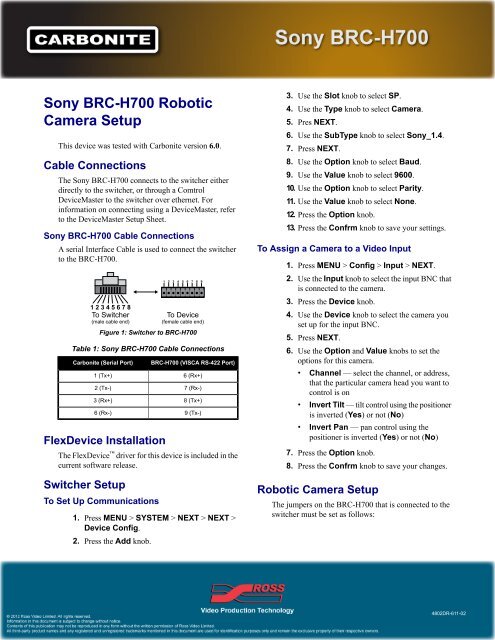
<strong>Sony</strong> <strong>BRC</strong>-<strong>H700</strong> Cable Connections<br />
A serial Interface Cable is used to connect the switcher<br />
to the <strong>BRC</strong>-<strong>H700</strong>.<br />
Figure 1: Switcher to <strong>BRC</strong>-<strong>H700</strong><br />
Table 1: <strong>Sony</strong> <strong>BRC</strong>-<strong>H700</strong> Cable Connections<br />
Carbonite (Serial Port)<br />
1 (Tx+)<br />
2 (Tx-)<br />
3 (Rx+)<br />
6 (Rx-)<br />
FlexDevice Installation<br />
<strong>BRC</strong>-<strong>H700</strong> (VISCA RS-422 Port)<br />
6 (Rx+)<br />
7 (Rx-)<br />
8 (Tx+)<br />
9 (Tx-)<br />
The FlexDevice driver for this device is included in the<br />
current software release.<br />
Switcher <strong>Setup</strong><br />
To Set Up Communications<br />
1. Press MENU > SYSTEM > NEXT > NEXT ><br />
Device Config.<br />
2. Press the Add knob.<br />
3. Use the Slot knob to select SP.<br />
4. Use the Type knob to select <strong>Camera</strong>.<br />
5. Pres NEXT.<br />
6. Use the SubType knob to select <strong>Sony</strong>_1.4.<br />
7. Press NEXT.<br />
8. Use the Option knob to select Baud.<br />
9. Use the Value knob to select 9600.<br />
10. Use the Option knob to select Parity.<br />
11. Use the Value knob to select None.<br />
12. Press the Option knob.<br />
13. Press the Confrm knob to save your settings.<br />
To Assign a <strong>Camera</strong> to a <strong>Video</strong> Input<br />
1. Press MENU > Config > Input > NEXT.<br />
2. Use the Input knob to select the input BNC that<br />
is connected to the camera.<br />
3. Press the Device knob.<br />
4. Use the Device knob to select the camera you<br />
set up for the input BNC.<br />
5. Press NEXT.<br />
6. Use the Option and Value knobs to set the<br />
options for this camera.<br />
• Channel — select the channel, or address,<br />
that the particular camera head you want to<br />
control is on<br />
• Invert Tilt — tilt control using the positioner<br />
is inverted (Yes) or not (No)<br />
• Invert Pan — pan control using the<br />
positioner is inverted (Yes) or not (No)<br />
7. Press the Option knob.<br />
8. Press the Confrm knob to save your changes.<br />
<strong>Robotic</strong> <strong>Camera</strong> <strong>Setup</strong><br />
The jumpers on the <strong>BRC</strong>-<strong>H700</strong> that is connected to the<br />
switcher must be set as follows:<br />
4802DR-611-02
2<br />
<strong>Camera</strong><br />
Address<br />
Switch 1<br />
Switch 2<br />
Switch 3<br />
Switch 4<br />
Table 2: Bottom Switches Settings<br />
Switch<br />
1<br />
2<br />
3<br />
4<br />
Value<br />
No connection<br />
Set to ON for RS-422<br />
communications<br />
Set to OFF for 9600 baud rate<br />
Infra-red signal control (OFF)<br />
disables the control<br />
Table 3: <strong>Camera</strong> Address Selector<br />
1<br />
ON<br />
OFF<br />
OFF<br />
2<br />
OFF<br />
ON<br />
OFF<br />
3<br />
ON<br />
ON<br />
OFF<br />
4<br />
OFF<br />
OFF<br />
ON<br />
not used<br />
5<br />
ON<br />
OFF<br />
ON<br />
6<br />
OFF<br />
If you are daisy chaining multiple <strong>Sony</strong> <strong>BRC</strong>-<strong>H700</strong><br />
<strong>Robotic</strong> <strong>Camera</strong>s together, use the following pinouts to<br />
connect the one camera to the next.<br />
ON<br />
ON<br />
Table 4: <strong>Camera</strong> to <strong>Camera</strong> Cable Connections<br />
VISCA Out<br />
1 (DTR)<br />
2 (DSR)<br />
3 (Tx)<br />
4 (Gnd)<br />
5 (Rx)<br />
VISCA In<br />
2 (DSR)<br />
1 (DTR)<br />
5 (Rx)<br />
4 (Gnd)<br />
3 (Tx)<br />
7<br />
ON<br />
ON<br />
ON