"lfk f; \"A Lt. - Airborne Systems
"lfk f; \"A Lt. - Airborne Systems
"lfk f; \"A Lt. - Airborne Systems
Create successful ePaper yourself
Turn your PDF publications into a flip-book with our unique Google optimized e-Paper software.
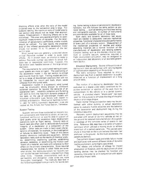
Blocking effects arise when the ratio of the model<br />
projected area to the test-section area is large. For<br />
subsonic testing, the maximum ratio of model area to<br />
test section area should not be larger than approximately<br />
fifteen-percent if blocking effects are to be<br />
minimized. This area ratio applies primarily to opening-shock<br />
measurements of canopies- For the determination<br />
of aerodynamic coefficients, smaller models<br />
should be utilized. For best results. the projected<br />
area of the inflated aerodynamic decelerator model<br />
should not exceed 10 to 15 percent of the tes:<br />
sert:on area.<br />
Wind tunnel testS are generally conducted above<br />
critical Reynolds number in order to avoid scale<br />
efieGts. As in aircraft we,rk, an 2ttempt is made to<br />
achieve Reynolds number equivalent to actual fullscale<br />
test or operational conditions; however, this<br />
has seldom been feasible because o the la-ge canopy<br />
diarleter3.<br />
The requirements for wind tunnel testing at supersonic<br />
speeds are more stringent. The positioning of<br />
the decelerator model' the test section is critical<br />
and mounts must be rigid. Trailing models are limited<br />
to a range of downstream positions that will not<br />
be intersected by mount and body shock waves<br />
reflected from the tunnel walls.<br />
Decelerat:lf models in a supersonic wind tunnel<br />
must be structurally strong enough to withstand<br />
sustained operation far beyond the demands of an<br />
operational item. Instability pulsation and fluttering<br />
will tend to limit the maximum dynamic pressure of<br />
the tests, or the use of over-strength models will<br />
introduce unfavorable sl:ale factors with respect to<br />
stiffness and elasticity. Wind tunnel facilities currently<br />
used for testing supersonic decele'ator tvoes are<br />
located at the Arnold Air Force Station , Tennessee.<br />
Support Testing<br />
Support tests are those conducted on recovery system<br />
components and materials to obtain, at low cost,<br />
functional verific8liCln or spec ;tic data in support of<br />
(and usually prior to) expensive major development<br />
operations such as flight testing. Ground tests or<br />
bench tests are often used to demonstrate functional<br />
integrity of a decelerator or a component of the<br />
system. Other tests are made to learn exact charac.<br />
teristics of materials, for example, in the investigation<br />
of failures to determine cause- Tests of this nature<br />
employ laboratory methods and equipment. Simple<br />
laboratory tests, such as the results of chemical analy.<br />
sis, determining weathering qualities, establishing<br />
abrasion resistance, or determining the friction coef.<br />
ficient of a material , are made with reference to their<br />
effect on the primary characteristics. Since required<br />
characteristics for textiles in other fields are somewhat<br />
similar, the testio;J equipment for recovery system<br />
textiles has been borrowed or adapted from these<br />
other tields. However, chfJr"cteristics such as air<br />
perneabilit' and elongation IJIder stress are more<br />
thoroughlV investigated. The methods described in<br />
the fOllowing paragraprs are primarily for textile test-<br />
207<br />
ing. Some testing is done on aerodynamic decelerator<br />
hardware, but this follows the same pattern as any<br />
metal testing. such as bending and hardness testing<br />
and radiographic analysis. A number of instruments<br />
are commercially available for all of these tests.<br />
Both static and dynamic labOFatory test equiprnept<br />
are needed to adequately evaluate mechanical<br />
properties, functional characteristics and performance<br />
of every part of a recovery system. Measurement of<br />
the mechanical properties of textiles and energy<br />
absorbing materials are a normal function of the<br />
manufacturers of decelerator and landing systems.<br />
Complox testing, such as the discrete vibration spectrum<br />
or extreme vacuum , sometimes required in<br />
flight environment simulation, may be<br />
delagated tQ<br />
an independen: test laboratory or an available government<br />
facility.<br />
Simulated Deproyment.<br />
Sa'.teral different kinds of<br />
deployment tests are performed with varying degrees<br />
of s::phistication dependirg on the purpose.<br />
The static extraction force required to strip a<br />
deployment bag fr8m a packed decelerator is usually<br />
measured as a function of displacement on a long<br />
smooth .table.<br />
The mo1ion of a deploying decelerator may be<br />
evaluated to a degree und8r static conditions by impu!sive<br />
extraction or ejection of the pack from its<br />
comps:tment in the vehicle or in a partial dummy<br />
vehicle. A stretched elastic "shock-cord" has been<br />
used for this pl.rpose to sirrulate the drag of the pilot<br />
chute or prior-stage drogue.<br />
Static mortar firings and ejection tests may be performed<br />
with either dummy or actual decelerator<br />
packs to evaluate muzzle velocities and the behavior<br />
of the decelerator and dep! oyment bag during the<br />
stretchou t sequ ence .<br />
Recovery system deployment sequencing may be<br />
eva\uated with actual or dUMmy vehicles at rest on<br />
the ground for detailed instrumental and photographic<br />
coverage of the complete series of events in re61<br />
time. Reference 324 describes a dynamic sinulation<br />
technique which utilized a moving truck to achieve<br />
stretch out of a packed parachute. The packed parachGte<br />
is mounted on the truck bed and the main riser<br />
anchored :0 the ground, As the truck accelerates, the<br />
parachute deploys,<br />
Deployment impact loads and bridle failure modes<br />
are dup!ica:ed with several different kinds of dyrwmic<br />
loading equipment, some highly specialized.<br />
The release and inflation of airbags for impact<br />
attenuation or flotation, and the deployment of other<br />
landing devices may be checked for function and<br />
operating time prior to or in conjunction with appropriate<br />
drop impact tests


