- Page 1 and 2:
AFFDL- TR-78-151 IRVIN INDUSTRIES I
- Page 3 and 4:
UNCLASSIFIED SECURITY CLASSIFICATIO
- Page 5 and 6:
. . . . . . . . . . . . CHAPTE R IN
- Page 7 and 8:
. . . . . . . . . . . . . CHAPTER 4
- Page 9 and 10:
CHAPTE R 6 (Cont) RELIABILITY Typic
- Page 11 and 12:
GURE 1.2 1.4 1.5 1 10 1-1 1 12 1 13
- Page 13 and 14:
FIGURE 3.40 3.41 3.42 3.43 3.44 3.4
- Page 15 and 16:
FIGURE 6AD 10A 10B . . . . . . . .
- Page 17 and 18:
LIST OF ILLUSTRATIONS (Continued) U
- Page 19 and 20:
FIGURE 7.45 7.4 7 7.48 7.49 LIST OF
- Page 21 and 22:
i'Jz dl.'lI/b"W"O","'"' J! L E 101
- Page 23 and 24:
GDA LIST Of SYM BO LS - Area (cross
- Page 25 and 26:
ob Mass of Body I ncluded Mass Any
- Page 27 and 28:
X-r r/c SYMBOLS (Continued) - Numbe
- Page 29 and 30:
Inertial Elasticity Canopy ventilat
- Page 32 and 33:
INTRODUCTION Recovery is a term pop
- Page 34 and 35:
deceleration stages were possible b
- Page 36 and 37:
TABLE B WEIGHTS AND MEASURES Length
- Page 38 and 39:
Z, (- y% T AS LE C PROPERTIES OF EA
- Page 40:
TABLE D TYPICAL GROUND WIND VELOCIT
- Page 43 and 44:
VEHICLE RECOVERY Vehicle!; that hav
- Page 45 and 46:
. . Recovery was initiated with pne
- Page 47 and 48:
vehicle enters the continuum flow a
- Page 49 and 50:
They "re scheduled to arrive in Dec
- Page 51 and 52:
SeparB riot! Entrv Figure 1. T=O Fi
- Page 53 and 54:
TABLE 1.1 TECHNICAL DATA OF THE MER
- Page 55 and 56:
as lsed 0, the Mercury C:8psule. AI
- Page 57 and 58:
Three Main rachut:s Fxtracted by Mo
- Page 59 and 60:
Back-up Drogue Chute PIV Steel Cabl
- Page 61 and 62:
95 Suspension Lines Number of parac
- Page 63 and 64:
Reference 32 suggests certain appli
- Page 65 and 66:
chute and slightly decreases the ve
- Page 67 and 68:
TABLE 1. S. NAVY PERSONNEL EMERGENC
- Page 69 and 70:
pilot chute extraction, independent
- Page 71 and 72:
Canopy Inflated Survival Kit Releas
- Page 73 and 74:
58 Encapsulated Seat. The 8-58 airc
- Page 75 and 76:
300 tOO 'l1j V- C- Stabilization Br
- Page 77 and 78:
TABLE 1.8 AIRCRAFT USED FOR AI'DROP
- Page 79 and 80:
These requirements have resulted in
- Page 81 and 82:
The advantages of the LAPES airdrop
- Page 83 and 84:
Con:ainer, Platform Piatform Weight
- Page 85 and 86:
defeated the low cost aspect. ::ffo
- Page 87 and 88:
, , Figure 26 10. Personnel Troop P
- Page 89 and 90:
Design TABLE 1 13 T. 10 PARACHUTE A
- Page 91 and 92:
In operation, the a rcraft pilot ma
- Page 93 and 94:
ment bag should closely contain the
- Page 95 and 96:
' TABLE 1. PARACHUTE SYSTEMS FOR SP
- Page 97 and 98:
ORDNANCE The application of aerodyn
- Page 99 and 100:
Figure 33 Mark 82 AID Inflation 0 ;
- Page 101 and 102:
AERIAL PICKUP Aerial pickup is one
- Page 103 and 104:
Figure 34 Trapaze/Helicopter (HH-53
- Page 105 and 106:
Main Parachute as Suspension Lines
- Page 107 and 108:
Other Mid.air Retrieval Concepts. B
- Page 109 and 110:
apid turn rates. and minimal weight
- Page 111 and 112:
door of a cradle rrounted platf:rm
- Page 114 and 115:
CHAPTER 2 DEPLOYABLE AERODYNAMIC DE
- Page 116 and 117:
TABLE . 2. SOLID TEXTILE PARACHUTES
- Page 118 and 119:
Type Taja, TU Slots, etc. LeMoigne
- Page 120 and 121:
BIAS il BLOCK Figure 2. Flet Patter
- Page 122 and 123:
Specific; rdcrcncc data are listed
- Page 124 and 125:
.( Con ical. The ca'loPY is constru
- Page 126 and 127:
! , Trj. Conical. The canopy is co,
- Page 128 and 129:
Full Extended Skirt. The canopy is
- Page 130 and 131:
Guide Surface, Ribbed. The canopy i
- Page 132 and 133:
Panels ROOF PATTRN X/I1, .70 Y/X 60
- Page 134 and 135:
- = Cross. The cross parachute, a F
- Page 136 and 137:
Slotted Canopy Parachutes Flat Circ
- Page 138 and 139:
Hemisflo. The constructed shape of
- Page 140 and 141:
--- Ringsail. This parachute design
- Page 142 and 143:
Rotating Parachutes Rotation Df par
- Page 144 and 145:
Low G!ide Parachutes gliding paracr
- Page 146 and 147:
'" Parawing, Single Keel. Tfe canep
- Page 148 and 149:
Parafoil. The canopy is cOlstructed
- Page 150 and 151:
DECELERATORS OTHER THAN PARACHUTES
- Page 152 and 153:
CHAPTER 3 COMPONENTS AN SU BSYSTEMS
- Page 154 and 155:
drogue and starts the timer which o
- Page 156 and 157:
alloth r is the pyrotechnic delay t
- Page 158 and 159:
that an'! Ai r- Iaunched from a car
- Page 160 and 161:
Catapult/Telescoping Thruster. Tele
- Page 162 and 163:
Inflation Phase Actuators. Pym/mech
- Page 164 and 165:
\()\ \, '.. , i. ,, / " .. $) -' .,
- Page 166 and 167:
Figure 18 Cargo Parachute Release 5
- Page 168 and 169:
Figure 21 AlP 28S-2 Personnel Harne
- Page 170 and 171:
wiDensi on Linlis 'I, Gre;ur.d t_C
- Page 172 and 173:
Bridles. A bridle IS :J connectirg
- Page 174 and 175:
Sus,GfinsiQn Line Sigh -Sleeve Mout
- Page 176 and 177:
Figure 38 Representative Cargo Harn
- Page 178 and 179:
, ':"' -." (, ::. :: - , :..' ' , .
- Page 180 and 181:
sharp edged corner knifes into the
- Page 182:
compartments or in ex ernal fairing
- Page 185 and 186:
from the air , and hydrogen from wa
- Page 187 and 188:
ather tran measuring its cross-sect
- Page 189 and 190:
tion potential. The first !;::lunll
- Page 191 and 192:
(%) TABLE 4. (cont'd) MECHANICAL PR
- Page 193 and 194:
'R 1000 800 600 400 200 1000 800 60
- Page 195 and 196:
For a hypothetical fabric composed
- Page 197 and 198:
TABLE 4. NYLON SEWING THREADS Data
- Page 199 and 200:
TABLE 4. THREAD , NYLON , NON MELTI
- Page 201 and 202:
Type Iia Iii I'la -1!L VII VIII XII
- Page 203 and 204:
Narrow Woven Fabrics. The strength
- Page 205 and 206:
111 Yarn: Color: Ident Use: Min. Br
- Page 207 and 208:
TABLE 4. 19 POLYESTER WEBBING, IMPR
- Page 209 and 210:
TABLE 4. 23 (Continued) Dqta horn M
- Page 211 and 212:
(%) TABLE 4. RAYON TAPE AND WEBBING
- Page 213 and 214:
(%) TABLE 4 a from MI ranee 260 Cia
- Page 215 and 216:
Type III Weave: Finish: Use: TABLE
- Page 217 and 218:
TABLE 4. NYLON DUCK Data from MI L-
- Page 219 and 220:
yarns. In order to achieve low air
- Page 221 and 222:
!. Entrapped air in the cells contr
- Page 223 and 224:
method of joining textiles. Strong,
- Page 225 and 226:
However. if tile strength of the cl
- Page 227 and 228:
;: =::~~~~~~~~~ ::: ::.. "':;.. - -
- Page 229 and 230:
_._--_.- -------- ---- ------ -----
- Page 231 and 232:
--- -".. , ;;;" / . ----- ------- -
- Page 233 and 234:
width sec ion dimensions based on t
- Page 235 and 236:
and length depend on the type parac
- Page 237 and 238:
has become cOr/mon practice to x-ra
- Page 239 and 240:
TEST METHODS AND CAPABILITIES Selec
- Page 241 and 242:
cescent, drift terden::es, and ethe
- Page 243 and 244:
supported at other bases including
- Page 245 and 246:
stant of release, the free-flving p
- Page 247 and 248:
Figure 5.7 for the same type in wat
- Page 249 and 250:
Function and Performance Checks. Re
- Page 251 and 252:
Laboratorv apparatus has been assem
- Page 253 and 254:
The coeff icient of sl idin g frict
- Page 255 and 256:
White Sands Misslfe Range Texas Hol
- Page 257 and 258:
TABLE 5. DECELERATOR TESTING, PRINC
- Page 259 and 260:
allistics tEst tracks and special p
- Page 261 and 262:
atmospheric wind tunnel Tre test se
- Page 263 and 264:
i ng and launching models wh de the
- Page 265 and 266:
TEST VEHICLES In a free flght test
- Page 267 and 268:
Load-Searing Platform Paper Honeyco
- Page 269 and 270:
338 with an operation has been obta
- Page 271 and 272:
1, Central part of housing 2. Upper
- Page 273 and 274:
to the appl ied stifTl lus. In gene
- Page 275 and 276:
:ll€thod available is provided by
- Page 277 and 278:
The different deployrrent methoDs f
- Page 279 and 280:
a: 30 .. 60 t: 20 18 10 AV6r6ge New
- Page 281 and 282:
.q:.Q 1.0 002 -- ,. ,. '0. 1.. P (C
- Page 283 and 284:
2000 1000 Lbs Force Snatch Farce bp
- Page 285 and 286:
,\ )\' ""' Ij, !i!t: a) Opening of
- Page 287 and 288:
1.0 HORIZONiAL TRAJECTORY ft H. S.
- Page 289 and 290:
The Inflation 0 " clustered canopie
- Page 291 and 292:
"' area across the canopy s the gov
- Page 293 and 294:
j '" . =: qlide) and ringsail desig
- Page 295 and 296:
Canopy Type C-9 Canopy Con fig A Sn
- Page 297 and 298:
si'" 9 Configuration: 9 ConfiglJrti
- Page 299 and 300:
::. ::". :::. , " .:.' I I Ii 1! l4
- Page 301 and 302:
Figure 6, j; 5"O 540 u. :z 12 o 1.
- Page 303 and 304:
Fioure 27 Opening Force- Time Histo
- Page 305 and 306:
'" Axial Force Coefficient I t is c
- Page 307 and 308:
CAo 35 OM-O. a, Degrees Angle of At
- Page 309 and 310:
. /;. ;. - .'; , . .\. . ~~~ : ;:.
- Page 311 and 312:
LID .. .. Hlen Gliding: W"'W FC08(J
- Page 313 and 314:
Proiect System Descent Parachute We
- Page 315 and 316:
;J = I .. !-- 1// 10. i- ,\;y q.. C
- Page 317 and 318:
-.rQ W/. '" 300 '" 2.35 PSF TURN RA
- Page 319 and 320:
db == p' Mgr ,, ". .. al Velocity D
- Page 321 and 322:
;. ti c: 1). 0.4 C-' -.- --- .. - '
- Page 323 and 324:
TABLE 6.9 MID-AIR RETRIEVAL SYSTEM
- Page 325 and 326:
three dimensional body ha'Je been s
- Page 327 and 328:
;'1 Fig. 6. 55. For a given Mach nU
- Page 329 and 330:
CDo 0.4 'siD LJ 0,. 0 1. Ipd 4.70 0
- Page 331 and 332:
-- I- l- -2 /:INCR c)-200 lo/in Nyl
- Page 333 and 334:
(J f. :' ' - ... . -- ' ;,' ; .; '-
- Page 335 and 336:
p. 'e- - - - - - - - - - - - - ven)
- Page 337 and 338:
2 0. 0.4 0. REEFING RATIO D,ID Figu
- Page 339 and 340:
lengths during deplovment and openi
- Page 341 and 342:
(CoSJ o varies with in the same way
- Page 343 and 344:
Flar Circular Conical 10'1 Extended
- Page 345 and 346:
-2.4 1.6 1.2 -0.4 0.4 0.4 a! Model
- Page 347 and 348:
flralleJ and the (-- to X Axis Cent
- Page 349 and 350:
a) Tap View of MARS Axis SV5tems OI
- Page 351 and 352:
- ----- --- Figure 6. 48 Ft Ribbon
- Page 353 and 354:
""' . it -; 1. " _._,.- 0.4 measure
- Page 355 and 356:
:9 0. 20. 0.40 Q; O. 10 -0_05 0. -0
- Page 357 and 358:
ing points of poIY'TIers , their sp
- Page 359 and 360:
2500 (A) Ascent 2000 1500 100 500 I
- Page 361 and 362:
Water Impact (Spla$hdown) In a wate
- Page 363 and 364:
where is the instantaneous r:eight
- Page 365 and 366:
Bag 'Material.NvllJn Cloth! Narsyn
- Page 367 and 368:
.. , , ; . '(. ., ' .. . ! '.: \ '
- Page 369 and 370:
Human error is more difficult to de
- Page 371 and 372:
TABLE 14 8-YEAR SUPPL Y/EQUIPMENT D
- Page 373 and 374:
Scale Camp ressibillty Factor Fluid
- Page 375 and 376:
"' been unlocked. :he bag offers ve
- Page 377 and 378:
() = Drogue Parachute Angle of Atta
- Page 379 and 380:
270 180 o - 120 Pe rcent Per See 6
- Page 381 and 382:
€ = PI .. velocity of mass added
- Page 383 and 384:
e f312JK PICoSJ1I2 (C (CDS! n((CD S
- Page 385 and 386:
D fDrii(! Coeffcient For Ul1iform M
- Page 387 and 388:
:: . 0. .. Aluminum Canopies fDp 6.
- Page 389 and 390:
axial and radial acceleration of th
- Page 391 and 392:
Iy in Figs. 7. 14b and c. Inflating
- Page 393 and 394:
p, '" '" inflowin9 air is subjected
- Page 395 and 396:
Gore Dimensions Warp or Fil Inflate
- Page 397 and 398:
The posi tive internal differential
- Page 399 and 400:
d) View of Plane A- el View of Plan
- Page 401 and 402:
area '" (R/ /2Jf2(J-sin := g., The
- Page 403 and 404: COMPUTE ,,, ASSUME TRIAL CONVERGENC
- Page 405 and 406: Note: ABterisk denote, inPt/f bvana
- Page 407 and 408: at a) Canopy Tension Approach Tsnoe
- Page 409 and 410: _-- "" - .. -.. (fnviscid) Wake Qf
- Page 411 and 412: easonable to use Reynolds and Nusse
- Page 413 and 414: Figure 7. ReD x 10 t: 3. 'V 4.42 .
- Page 415 and 416: = 10. iFf: = 1. 86 x 10 Deg. Deg ,!
- Page 417 and 418: If/db Figure 34 Wake Coefficients v
- Page 419 and 420: A prima ry and obvious limitation o
- Page 421 and 422: tive drag stabilizer because of ii:
- Page 423 and 424: tVa (min- (min. ) . '" M/M .4 . Mr!
- Page 425 and 426: Angle of Atteck Deg S R8 &12 See In
- Page 427 and 428: '" 0.4 Ex"eriment iSSinger Nt) Adju
- Page 429 and 430: Jt (See XI0) e IGz J (3) (4) FPS (6
- Page 431 and 432: point the discharge or tices open.
- Page 433 and 434: FPS K. 10. f( 60 80 100 - Lb Sec/Lb
- Page 435 and 436: they are analogm.. s to the inacleq
- Page 437 and 438: "" usr=d in th 8 computations. The
- Page 439 and 440: desc-ibed in References 285 and 552
- Page 441 and 442: pre-seleCting the final confidence-
- Page 443 and 444: g., system is to be identified. Thi
- Page 445 and 446: '/, too heavy., too bulky or too lo
- Page 447 and 448: t. 14 -- .: Jlten d ed SkI Ffar Cir
- Page 449 and 450: Surface af Revolution: ; -1 Gore La
- Page 451 and 452: TABLE 8.3 SYSTEM A OPENING FORCES (
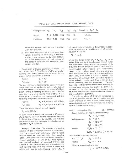
- Page 453: '" '" '" "" 156 '" 3 D,IDo 10 (reef
- Page 457 and 458: adial distance a, ong the surf"ce f
- Page 459 and 460: TABLE 8. STEERABLE PARACHUTE COMPAR
- Page 461 and 462: Portion of canopy Sockiri up Fourth
- Page 463 and 464: followed to create a sequence of ca
- Page 465 and 466: ond /db =" 8. 3/5 7 D /CDt; Appra,s
- Page 467 and 468: I'ne rraterfal required is 18 1583
- Page 469 and 470: Unlock Action Riser Closure Flaps (
- Page 471 and 472: '" "" "" = . where (see Page 344) p
- Page 473 and 474: '), w m.rif 305 Mo' ar weight, m 18
- Page 475 and 476: ecause the le1gth of riser branches
- Page 478 and 479: ( .,." ' 727J . ' LIST OF REFEi=ENC
- Page 480 and 481: 104 LIST OF REFERENCES (Continued!
- Page 482 and 483: 138 141 144 146 147 148 149 150 151
- Page 484 and 485: 206 207 208 209 210 Z), 212 213 214
- Page 486 and 487: 290 291' 293 294 295 296 297 298 29
- Page 488 and 489: 353 354 355 356 357 358 359 364 365
- Page 490 and 491: 411 412 413 414 415 416 417 418 419
- Page 492 and 493: 463 464 465 466 467 468 469 470 471
- Page 494 and 495: ..'- 524 525 526 527 533 534 535 53
- Page 496 and 497: Acceleration Measurement, 232 Actua
- Page 498 and 499: Pressure Distribution , 227 Strain,