Sensor Owner's Manual 1997 - Trek Bicycle Corporation
Sensor Owner's Manual 1997 - Trek Bicycle Corporation
Sensor Owner's Manual 1997 - Trek Bicycle Corporation
Create successful ePaper yourself
Turn your PDF publications into a flip-book with our unique Google optimized e-Paper software.
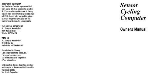
COMPUTER WARRANTY<br />
Your <strong>Trek</strong> <strong>Sensor</strong> Computer is guaranteed for 2<br />
years against defects in workmanship or materials.<br />
If you experience problems refer to the suggestions<br />
in the troubleshooting guide in this manual.<br />
If this does not solve your problem, please<br />
return the computer to your authorized <strong>Trek</strong><br />
Dealer or send the computer postage paid to:<br />
<strong>Trek</strong> <strong>Bicycle</strong> <strong>Corporation</strong><br />
Attn. Computer Warranty Dept.<br />
801 W Madison Street<br />
Waterloo, WI 53594 USA<br />
TREK UK<br />
Attn. Computer Warranty Dept.<br />
15 Old Bridge Way<br />
Bedfordshire, SG17 5HQ ENGLAND<br />
Please include the following:<br />
1. The complete computer (wiring, etc.)<br />
2. A copy of your sales receipt<br />
3. A brief explanation of the problem<br />
4. Your return address<br />
For 2 years from the date of purchase, a replacement<br />
computer of the same model will be sent to<br />
you postage paid by<br />
<strong>Trek</strong> <strong>Bicycle</strong> <strong>Corporation</strong>.<br />
<strong>Sensor</strong><br />
Cycling<br />
Computer<br />
Owners <strong>Manual</strong>
TREK OWNERS MAUAL<br />
Congratulations and thank you for<br />
purchasing the <strong>Trek</strong> <strong>Sensor</strong> Bicycling<br />
Computer! The New <strong>Trek</strong> <strong>Sensor</strong> represents<br />
the latest in bicycle computer technology,<br />
concepts with features that can<br />
greatly enhance the riding experience of any<br />
cyclist, whether they are a recreational<br />
rider or a top notch racer. The <strong>Trek</strong> <strong>Sensor</strong><br />
may actually change the way you ride your<br />
bicycle!<br />
PARTS LIST<br />
2<br />
SENSOR LCD SCREEN<br />
WARNING<br />
Please read this instruction manual<br />
carefully and save this manual for<br />
future reference.<br />
Precautions<br />
Remember to watch the road while<br />
riding. Watching your bicycle computer<br />
makes it difficult to see upcoming<br />
obstacles. Awareness of potential road,<br />
trial, or traffic problems should be your<br />
main concern.<br />
Never place fingers near the spokes of a rotating wheel or<br />
other moving parts which could cause injury.<br />
Watch where you are going when riding your bicycle. Inattention<br />
may cause a loss of control resulting in personal injury.<br />
COMPUTER FUNCTIONS<br />
Speedometer Display (SPD)<br />
Current riding speed is indicated on the top<br />
line of the display with the SPD icon.<br />
Instantaneous speed has a display range of<br />
2.5 – 99.5 M/h (4 – 99.5 Km/h).<br />
Automatic Timer Stopwatch<br />
(ATM)<br />
The Automatic Timer Stopwatch is<br />
displayed on the lower line with the ATM<br />
icon. The ATM stopwatch is automatically<br />
activated by wheel movement. It cannot be<br />
manually turned on or off, and records only<br />
the time spend actually riding. To clear<br />
stored information and get ready for your<br />
next ride, enter SPD/ATM display mode<br />
and press both keys for over 2 seconds. This<br />
will clear all resetable functions (ATM,<br />
DST,<br />
AVS & MXS).<br />
Speed Comparison Display<br />
When riding, a + or – icon will appear<br />
to the right of the current Speed display.<br />
A + icon indicates that your current speed<br />
is faster than your recorded<br />
average speed. A – icon means you are<br />
traveling slower than your recorded average<br />
speed.<br />
Trip Distance (DST)<br />
Trip Distance is displayed on the lower line,<br />
indicated by the DST icon. Trip<br />
distance is tied to the ATM stopwatch, and<br />
records automatically when riding. Trip<br />
Distance records up to 999.9 miles (or<br />
Kilometers), with a resolution of 0.1<br />
miles/kilometers.<br />
AVG<br />
Average Speed (AVS)<br />
Average Speed is displayed in 0.1 mi/Km<br />
increments on the upper line, indicated by<br />
the AVS icon. AVS is calculated with the<br />
Auto Timer Stopwatch and is the average<br />
speed only for time spent<br />
actually riding.<br />
Odometer (ODO)<br />
The cumulative distance traveled for all<br />
rides is displayed on the lower line,<br />
indicated by the ODO icon. Total Odometer<br />
can be cleared to 0 by pressing the All Clear<br />
button on the bottom of the computer or by<br />
removing and re-installing the battery.<br />
3
Maximum Speed (MXS)<br />
The Maximum Speed reached during a ride is<br />
displayed in 0.1 mi/Km increments on the<br />
top line, with the MXS icon. Maximum<br />
Speed is stored in<br />
memory and is updated each time a new,<br />
higher speed is reached.<br />
CLOCK (CLK)<br />
The 12 hour clock is displayed on the lower<br />
line, indicated by the CLK icon.<br />
ATM “Lap Timer” Display<br />
A unique ATM “Lap Timer” display allows<br />
you to lock the display at the end of a ride<br />
segment and view the ATM, DST, AVS<br />
and MXS at a later time.<br />
This is especially useful at the end of a race,<br />
allowing you time to cool down without<br />
adding time to your Stopwatch.<br />
As you cross the finish line, press the left<br />
key for over 1 second to freeze information<br />
on the display. You may continue to ride,<br />
viewing the information locked on the flashing<br />
locked display. The computer will continue<br />
to record information and store it in<br />
memory. Press the left key to update the<br />
current display information.<br />
RESETTING THE COMPUTER<br />
In SPD/ATM mode, press both keys for over<br />
two seconds to clear ATM, DST, AVS and<br />
MXS display.<br />
SLEEP MODE<br />
To conserve battery power, the computer<br />
will enter the ‘Sleep’ mode after 5 minutes<br />
of no speed input, blanking the display.<br />
Press any key to enter normal operating<br />
modes.<br />
(Note: Unit will not enter sleep mode in<br />
setting function mode.)<br />
INSTALLATION<br />
<strong>Sensor</strong> and Wheel Magnet<br />
1. Position the sensor unit to the inside of<br />
either the right of left fork blade<br />
anywhere from 3-6 inches up from the fork<br />
blade tip. Attach the sensor to the fork<br />
blade with the quick ties but do not tighten<br />
the ties completely until final adjustment is<br />
complete.<br />
2. Attach the wheel magnet to a spoke,<br />
aligning the magnet with the sensor so it<br />
faces and intersects the bottom polished<br />
line on the sensor. The magnet should have<br />
1-2 mm clearance from the sensor. If the<br />
sensor and magnet are too close or touching,<br />
rotate the sensor unit toward the back<br />
of the fork blade until adequate clearance is<br />
achieved. Carefully tighten the quick ties<br />
making sure you maintain the proper space<br />
between the magnet and the sensor. Trim<br />
the excess quick tie strap using a scissors<br />
or fingernail clipper. Tighten the magnet<br />
screw, but be careful not to over tighten as<br />
this can damage the fitting.<br />
<strong>Sensor</strong> Wiring and Bracket<br />
1. Route the sensor wire up the back of the<br />
fork blade or wind the wire around the<br />
blade, making sure that the wire is not<br />
loose and that you leave enough wire to<br />
reach the handlebar. Secure the wire to the<br />
fork blade immediately above the sensor<br />
and at the top of the fork blade, using the<br />
adhesive strips<br />
that are provided or electrical tape.<br />
2. Wind the wire upward around the front<br />
brake cable until the wire is adjacent to the<br />
handlebar, allowing enough slack for free<br />
movement of the steering assembly cables.<br />
3. Attach the bracket to the handlebar on<br />
either side of the stem. The bracket goes<br />
onto the handlebar with the wire toward the<br />
rider side of the bar. Use the appropriate<br />
rubber shim between the bracket and handlebar<br />
to provide a secure fit.<br />
Shims will<br />
prevent slipping<br />
Attaching the Computer to<br />
the Bracket<br />
The <strong>Trek</strong> <strong>Sensor</strong> Computer attaches to<br />
the mounting bracket by sliding the unit<br />
onto the bracket from the back until it<br />
snaps firmly into position. To remove the<br />
computer from the bracket, place your<br />
thumb against the back of the mounting<br />
bracket and pull the computer toward you<br />
with your index finger.<br />
4 5
COMPUTER SET UP<br />
Battery Installation<br />
All Clear Button<br />
1. Remove the battery cover from the back<br />
side of the computer using a<br />
narrow flat blade screwdriver.<br />
2. Install the battery so that the<br />
positive "+" side of the battery is visible,<br />
and replace the battery cover.<br />
CAUTION: On the bottom of the computer<br />
head next to the battery door is a small<br />
recessed button. This is the Auto Clear<br />
Button. Pressing this button will clear all<br />
memories and reset all functions to their<br />
default values.<br />
BUTTON FUNCTIONS<br />
Mode Button<br />
Adjust<br />
Button<br />
The <strong>Sensor</strong> is equipped with 2 buttons that<br />
control the function of the unit.<br />
1. MODE<br />
Changes the Main Screens of the <strong>Sensor</strong><br />
2. ADJUST<br />
Adjusts digits while programming and<br />
activates ATM lap timer.<br />
PROGRAMMING YOUR TREK<br />
SENSOR CYCLE COMPUTER<br />
Setting the Clock<br />
1. Press the mode key to advance<br />
to MXS/Clock display.<br />
2. Press and hold the mode key for over 2<br />
seconds until hours setting<br />
begins to flash.<br />
3. Press the adjust key to adjust hours<br />
setting, press the mode key to confirm and<br />
advance to minutes setting.<br />
4. Press the adjust key (hold for fast<br />
advance) to adjust the minutes, and press<br />
the mode key to confirm setting and enter<br />
normal display mode.<br />
Setting Miles/ Kilometers and<br />
Wheel Size<br />
1. Press mode computer key to enter<br />
AVS/ODO mode.<br />
2. Press and hold mode key for over 2 seconds<br />
until m/h begins to flash.<br />
3. Press adjust key to select miles (m/h) or<br />
kilometers (km/h) display.<br />
4. Press mode key to confirm choice and<br />
advance to wheel size setting.<br />
5. Adjust the flashing digit with the adjust<br />
button, confirm choice by pressing mode<br />
button, and advance to next flashing digit.<br />
6. Adjust and/or confirm all flashing<br />
digits.<br />
Wheel Size Setting<br />
The wheel size setting number is equal to<br />
the distance, in millimeters, that your front<br />
wheel travels during one complete revolution.<br />
Each time the wheel magnet passes<br />
the sensor unit on your fork, the sensor<br />
sends an impulse to the computer telling it<br />
that your wheel has completed one revolution.<br />
The computer calculates this distance<br />
vs. time to give you accurate readings for<br />
the various modes.<br />
Determining Wheel Size Setting<br />
There are three methods for determining the<br />
wheel size setting. For the most accurate<br />
computer readings, it is best to measure the<br />
actual distance that your wheel travels in<br />
one complete revolution. This method is<br />
called a wheel roll out.<br />
Method One: Wheel Roll Out<br />
• Perform the wheel roll out on a hard,<br />
flat, smooth surface such as a garage or<br />
basement floor.<br />
• Make sure your tires are properly inflated.<br />
1. Position your bike so that the valve stem<br />
of the front wheel is at its bottom most<br />
position. Mark the spot on the floor directly<br />
under the center of the valve stem using a<br />
piece of tape or chalk.<br />
2. Roll the bicycle forward in a straight line,<br />
while putting downward pressure on the handlebars<br />
to simulate rider weight. When the<br />
wheel has completed one revolution and the<br />
valve stem is at its bottom position, mark the<br />
floor directly under the center of the valve<br />
stem with tape or chalk. Measure the distance<br />
between the two marks in millimeters. (Note:<br />
Conversion of in. to mm. is 1 in.=25.4 mm.)<br />
This is your wheel setting number. You can<br />
repeat this procedure and average your results.<br />
We recommend that you record your wheel setting<br />
numbers here for future reference.<br />
6 7
Method Two:<br />
Radius x 6.2832 = Wheel Setting<br />
Measure wheel radius (including tire) in<br />
mm and multiply by 6.2832=Wheel<br />
setting number.<br />
Method Three:<br />
Refer to the following chart and input the<br />
number that corresponds to your tire size.<br />
(Note: Actual size of two similarly marked<br />
tires from different<br />
manufactures can vary significantly, making<br />
this method the least accurate.)<br />
WHEEL SIZE CHART<br />
Wheel/Tire Size Wheel Size Setting<br />
in mm<br />
26 x 1.0 ATB . . . . . . . . .1913<br />
26 x 1.25 . . . . . . . . . . .1953<br />
26 x 1.5 . . . . . . . . . . . .1985<br />
26 x 1.9 . . . . . . . . . . . .2055<br />
26 x 2.0 . . . . . . . . . . . .2074<br />
26 x 2.1 . . . . . . . . . . . .2095<br />
26 x 2.2 . . . . . . . . . . . .2110<br />
700 x 20c . . . . . . . . . . .2074<br />
700 x 23c . . . . . . . . . . .2114<br />
700 x 25c . . . . . . . . . . .2124<br />
700 x 28c . . . . . . . . . . .2140<br />
700 x 32c . . . . . . . . . . .2155<br />
700 x 35c . . . . . . . . . . .2175<br />
700 x 38c . . . . . . . . . . .2180<br />
700 x 40c . . . . . . . . . . .2190<br />
650 x 20c . . . . . . . . . . .1945<br />
650 x 23c . . . . . . . . . . .1990<br />
Wide 700c Tubular . . . . . . . . .2117<br />
Narrow 700c Tubular . . . . . . .2105<br />
27 x 1” . . . . . . . . . . . .2145<br />
27 x 1-1/4 . . . . . . . . . . .2160<br />
ATB<br />
ROAD<br />
QUICK REFERENCE GUIDE<br />
Desired Function Which Key to Press Notes<br />
Advance Digits While Programming Left Key Hold for Fast Advance<br />
Set Digits While Programming Right Key<br />
Set Clock Right for 2 Sec. In MXS/Clock Screen<br />
Set Miles/Kilometers/Wheel Size Right for 2 Sec. In AVS/ODO Screen<br />
Enter ATM “Lap Timer” Display Left for 2 Sec In any Screen<br />
Reset ATM, DST, AVG and Max Right for 2 Sec. In SPD/ATM Screen<br />
TROUBLESHOOTING<br />
• No Speed Reading<br />
Improper magnet to sensor alignment,<br />
computer improperly installed<br />
in bracket.<br />
• Slow Display Response<br />
Temperature is outside operation<br />
limit (0˚-55˚C).<br />
• Display is Black<br />
Temperature is too hot. Remove from<br />
direct sunlight to return to<br />
proper operation.<br />
• Display Fades or Disappears<br />
Weak or dead battery, dirty<br />
battery contacts.<br />
• Irregular Display Figures<br />
Check and record Total Odometer, then<br />
press Auto Clear button to initialize<br />
computer. Follow setup procedure and<br />
adjust Odometer setting.<br />
8 9
RECORD DATA HERE<br />
RECORD DATA HERE<br />
10 11


