MAPAL Competence – Reaming and Fine Boring
MAPAL Competence – Reaming and Fine Boring
MAPAL Competence – Reaming and Fine Boring

Create successful ePaper yourself
Turn your PDF publications into a flip-book with our unique Google optimized e-Paper software.
High Performance Reamers<br />
<strong>MAPAL</strong> <strong>Competence</strong> –<br />
<strong>Reaming</strong> <strong>and</strong> <strong>Fine</strong> <strong>Boring</strong>
<strong>Competence</strong><br />
in <strong>Reaming</strong> <strong>and</strong> <strong>Fine</strong> <strong>Boring</strong><br />
To survive long-term as a reliable partner in today’s<br />
industrial world, it is particularly important to<br />
exp<strong>and</strong> <strong>and</strong> possess significant fields of competence<br />
with innovative products <strong>and</strong> customer<br />
services, with substantial product <strong>and</strong> technical<br />
know ledge. Only then can the customer <strong>and</strong> his<br />
business partners be certain in the long term to have<br />
come to the right place – in worldwide terms – for<br />
his in creasingly com plicated tasks in modern production<br />
processes. <strong>MAPAL</strong> has built up a whole<br />
range of such fields of competence, in dialogue<br />
with <strong>and</strong> for the use of their customers. As a initial <strong>and</strong><br />
important member of our “competence teams”, we should<br />
like to introduce you to the subject of reaming <strong>and</strong> fine<br />
boring with this brochure.<br />
Dr. Dieter Kress<br />
Managing Director
Index<br />
<strong>Competence</strong>, reliability <strong>and</strong> quality:<br />
Achieving the best boring results with <strong>MAPAL</strong> 4<br />
Successful tool solutions:<br />
Optimum tool concepts for every material 12<br />
Programme review 18<br />
Product index 21<br />
The <strong>MAPAL</strong> Principle:<br />
Tried <strong>and</strong> tested originals – diverse <strong>and</strong> st<strong>and</strong>ard 22<br />
The <strong>MAPAL</strong> Twin-bladed cutting tool:<br />
Higher performance with two blades 54<br />
The <strong>MAPAL</strong> precision indexable blades:<br />
Cutting leads, cutting materials, application areas 74<br />
The <strong>MAPAL</strong> High Performance Reamers:<br />
New opportunities with multi-bladed tools 80<br />
Examples from practice – for use in practice 128<br />
Introduction<br />
Tool solutions<br />
<strong>MAPAL</strong> Singlebladed<br />
tools<br />
<strong>MAPAL</strong> Twinbladed<br />
tools<br />
<strong>MAPAL</strong><br />
Indexable blades<br />
<strong>MAPAL</strong> HPR<br />
<strong>Competence</strong><br />
in practice
Engineering<br />
From production planning to production<br />
optimisation, a variety of service modules<br />
are available under the title CTS ® –<br />
Complete Tooling Services. Competent<br />
technical advice from the first enquiry<br />
to the production process in operation<br />
is seen by <strong>MAPAL</strong> as a natural duty.<br />
Experience, specialist tool experts work<br />
out the best possible process for your<br />
part. Once the tools are delivered,<br />
<strong>MAPAL</strong> offers any support needed for<br />
commissioning <strong>and</strong> h<strong>and</strong>ling the tools.<br />
Worldwide<br />
The best product, the optimum tool <strong>and</strong><br />
specific, rapid service are worth nothing<br />
if they are not offered or made constantly<br />
available where the customer actually<br />
needs them day to day. It is for this reason<br />
that for many years <strong>MAPAL</strong> has observed<br />
the motto “Wherever the customer is, you<br />
will find <strong>MAPAL</strong>”. Following the principle<br />
of this company policy, more than 20<br />
<strong>MAPAL</strong> sister manufacturing companies<br />
<strong>and</strong> service stations have been established<br />
worldwide <strong>and</strong> are available to customers<br />
in all the major industrial locations of the<br />
world, fully functional in daily operation<br />
with all <strong>MAPAL</strong> products <strong>and</strong> new cus -<br />
tomer services.<br />
Technology<br />
<strong>MAPAL</strong> actively grasps new <strong>and</strong> current<br />
production concepts, develops these to<br />
specific targets, tries them out in a com -<br />
prehensive test phase <strong>and</strong> translates<br />
them into customer-orientated solutions.<br />
In close dialogue with the customer <strong>and</strong><br />
starting with an example, the most<br />
suitable design for him is worked out<br />
<strong>and</strong> then continuously developed.<br />
Products<br />
The innovative tool designs from the<br />
<strong>MAPAL</strong> production line cover the whole<br />
area of precision machining. Precision<br />
machining tools, such as reaming, fine<br />
boring tools, gun boring tools, special<br />
tools with ISO elements, generating slide<br />
tools, plus PCD gun boring tools <strong>and</strong><br />
circular milling tools, cutter heads <strong>and</strong><br />
milling tools with tangential blades, to -<br />
gether with the whole programme for<br />
the high precision HSK Clamping System<br />
– from the st<strong>and</strong>ard tool to the specific<br />
solution <strong>MAPAL</strong> offers the perfect prod -<br />
uct for your machining task.<br />
7
1<br />
Twin-bladed Reamer Single-bladed Reamer<br />
HPR<br />
HPR Replaceable<br />
Reamer Head<br />
1<br />
<strong>MAPAL</strong> <strong>Competence</strong> – completed by<br />
the diversity of its products <strong>and</strong><br />
techno logy<br />
Today reaming <strong>and</strong> fine boring<br />
are the most widely used methods<br />
for precision machining<br />
bores. This produces highly<br />
economic machining results of<br />
the highest precision over the<br />
whole range of materials with<br />
reaming <strong>and</strong> fine boring tools<br />
with guide pads <strong>and</strong> with fixed<br />
multi-bladed reaming tools.<br />
<strong>MAPAL</strong> tools with indexable<br />
blades <strong>and</strong> guide pads – constantly<br />
developed <strong>and</strong> often<br />
trendsetters – are in use<br />
throughout the world today<br />
in a wide variety of designs.<br />
According to the machining<br />
task, these tools allow bore<br />
geometry <strong>and</strong> surface finishes<br />
which frequently make it<br />
possible to save on ad -<br />
ditional machining<br />
opera tions which were<br />
previously needed, such<br />
as grinding or honing.<br />
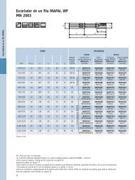
<strong>MAPAL</strong> WP Single-bladed Tools<br />
The <strong>MAPAL</strong> Single-bladed rea -<br />
mers are designed to <strong>MAPAL</strong>’s<br />
long-established principle. The<br />
cutting of the material <strong>and</strong> the<br />
guiding of the reamer in the<br />
bore is performed by the blades<br />
by means of pre cision grinding<br />
<strong>and</strong> guide pads located at the<br />
best geometric positions. The<br />
WP system is characterised by<br />
special cutting leads <strong>and</strong> exact<br />
adjustment in the diameter <strong>and</strong><br />
also back tapering. The perfectly<br />
aligned adjustment <strong>and</strong> clamping<br />
system for the blade guarantees<br />
optimum, play-free seating<br />
for the blade <strong>and</strong>, as a result,<br />
long tool life.
<strong>MAPAL</strong> HX Single-Bladed Tools<br />
Designed under the same principle<br />
as the WP single-bladed<br />
reamers, HX blades, with their<br />
six cutting edges, offer significant<br />
advantages for machining<br />
cast iron <strong>and</strong> steel. The HX cutting<br />
geometry is specially laid<br />
out for optimum chip flow <strong>and</strong><br />
short chips. In st<strong>and</strong>ard series,<br />
as NC reamers <strong>and</strong> for special<br />
tools, the economic advantages<br />
of the HX blades are particularly<br />
applicable.<br />
One important development of<br />
the single blade principle is the<br />
addition to the system of a<br />
further blade to make the<br />
<strong>MAPAL</strong> twin-bladed tool. The<br />
special arrangement of the<br />
two blades provides a microcutting<br />
function with<br />
which excellent sur -<br />
face finishes <strong>and</strong><br />
outst<strong>and</strong>ing tool<br />
life are achieved.<br />
<strong>MAPAL</strong> WP Twin-Bladed Tools<br />
The special performance fea -<br />
tures of the WP twin-bladed<br />
tools result from the position<br />
of the two blades in relation<br />
to one another. Because of<br />
the radial <strong>and</strong> axial offset, the<br />
follow-on blade only machines<br />
to a very small chip thickness.<br />
This produces noticeable in -<br />
creases in performance which<br />
is not only doubled but can be<br />
up to five times higher.<br />
<strong>MAPAL</strong> HX Twin-Bladed Tools<br />
The combination of the HX<br />
system with the special features<br />
of micro cutting opens up<br />
completely new opportunities<br />
for machining. By using the<br />
super cutting materials, PCBN<br />
<strong>and</strong> PCD for hard machining<br />
<strong>and</strong> for cutting cast materials,<br />
surface finishes <strong>and</strong> economic<br />
results are achieved which<br />
would have been unthinkable<br />
a short time ago. Honing <strong>and</strong><br />
grinding qualities are even<br />
achieved using this economically<br />
superior method <strong>and</strong><br />
make these operations superfluous.<br />
<strong>MAPAL</strong> Multi-Bladed Tools<br />
In addition to <strong>MAPAL</strong> tools<br />
with indexable blades, interesting<br />
new developments have<br />
also led to fixed multi-bladed<br />
reamers. With the new HFS®<br />
Head Fitting System, the<br />
<strong>MAPAL</strong> HPR High Performance<br />
Reamers achieve concentricity<br />
<strong>and</strong> changeover<br />
accuracy to microprecision<br />
<strong>and</strong> as a<br />
result meet the<br />
requirements for<br />
new dimensions in<br />
modern high performance<br />
cutting<br />
operations. Simple<br />
construction, direct coolant<br />
supply onto the blade, <strong>and</strong><br />
their consequent suitability for<br />
use with minimal lubrication<br />
<strong>and</strong> the large selection of<br />
cutting materials, make these<br />
<strong>MAPAL</strong> HPR reamers unique.<br />
9<br />
Introduction
10<br />
<strong>MAPAL</strong> <strong>Competence</strong> – completed by<br />
the diversity of products <strong>and</strong> techno logy<br />
<strong>MAPAL</strong> Special Tools<br />
<strong>MAPAL</strong> tools are primarily used<br />
for large batch production. The<br />
use of specially adapted tools<br />
often brings the economic so -<br />
lution for this.<br />
Because of the full programme<br />
of cutting systems the tool<br />
can be designed so that the<br />
optimum solution can be found<br />
<strong>and</strong> the best results achieved.<br />
Combinations of systems with<br />
modern cutting materials can<br />
also be good solutions for<br />
complex tasks.<br />
<strong>MAPAL</strong> Cutting Edges <strong>and</strong><br />
Cutting Materials<br />
In addition to the right selection<br />
<strong>and</strong> design of the tool’s construction,<br />
the decision for the<br />
right cutting material is also of<br />
great significance to the quality<br />
<strong>and</strong> economic results of a cutting<br />
operation. <strong>MAPAL</strong> offers a<br />
wide selection of cutting ma -<br />
terials here. Specially developed<br />
chipforming <strong>and</strong> chipbreaking<br />
structures produce the best<br />
possible chip flow. In various<br />
carbides <strong>and</strong> in Cermets in un -<br />
coated versions <strong>and</strong> a number<br />
of types of PCBN <strong>and</strong> PCD, optimum<br />
geometries are formed for<br />
chip control.
<strong>MAPAL</strong> Clamping Systems<br />
The consistent use of modern<br />
clamping systems by <strong>MAPAL</strong><br />
for high precision <strong>and</strong> perfect<br />
connections <strong>and</strong> interfaces<br />
bring the concentricity <strong>and</strong><br />
changeover accuracy required<br />
in modern production.<br />
Whether HSK or HFS®, both<br />
systems guarantee the<br />
necessary precision <strong>and</strong><br />
rigidity by means of the<br />
design features of the taper<br />
<strong>and</strong> the contact surface.<br />
Simple, precise <strong>and</strong> fast –<br />
plus flexible, safe <strong>and</strong><br />
economic – these are the<br />
requirements placed on<br />
systems in modern production<br />
technology. In conjunction<br />
with the long-established<br />
<strong>MAPAL</strong> reaming <strong>and</strong> fine<br />
boring tools, these requirements<br />
are met to a high<br />
degree <strong>and</strong> guarantee the<br />
user maximum productivity<br />
<strong>and</strong> measurable economic<br />
advantages.<br />
<strong>MAPAL</strong> HSK Clamping<br />
System<br />
With the constantly increasing<br />
spread of the hollow taper<br />
shank in all industries of<br />
modern production technology,<br />
<strong>MAPAL</strong> has developed a complete<br />
clamping system. The<br />
range of applications for<br />
<strong>MAPAL</strong> HSK clamping elements<br />
extends from special machines<br />
<strong>and</strong> transfer units to ma -<br />
chining centres <strong>and</strong> modern<br />
turning centres; whether for<br />
large batch production or for<br />
use in small <strong>and</strong> medium-size<br />
companies. In addition to the<br />
HSK clamping elements,<br />
<strong>MAPAL</strong> also offers a wide<br />
range of extensions <strong>and</strong><br />
reducers, together with<br />
adaptors <strong>and</strong> flange adapt -<br />
ors.<br />
This allows the combination<br />
drawn from high precision<br />
<strong>and</strong> high performance <strong>MAPAL</strong><br />
HSK clamping elements with<br />
precision reaming <strong>and</strong> fine<br />
boring tools from <strong>MAPAL</strong> to<br />
be adapted to any type of<br />
machine. Detailed information<br />
on <strong>MAPAL</strong> HSK clamping<br />
technology can be found in<br />
our separate special catalogue.<br />
<strong>MAPAL</strong> HFS® Head Fitting<br />
System<br />
The advantages of the HFS®<br />
Head Fitting System <strong>and</strong> the<br />
opportunities this provides for<br />
manufacturing, use <strong>and</strong> pre -<br />
paration of reaming heads<br />
are decisive to the success of<br />
these new tool series. Simple,<br />
easy access h<strong>and</strong>ling when<br />
changing tool heads, high<br />
flexibility with regard to special<br />
designs, a variety of cutting<br />
materials <strong>and</strong> diameters<br />
from 4 mm in the st<strong>and</strong>ard<br />
programme provide a large<br />
range of possible applications.<br />
As a result of the direct<br />
coolant supply onto the<br />
blade, the system is also<br />
extremely well suited for use<br />
with minimal or micro lubrication<br />
(MLC).<br />
11<br />
Introduction
12<br />
<strong>MAPAL</strong> <strong>Competence</strong> – Machining Aluminium<br />
In the car industry aluminium<br />
has special significance as a<br />
material for numerous com -<br />
ponents because of its low<br />
weight. Most components that<br />
are initially formed by casting<br />
often require complex bores<br />
with several steps, chamfers <strong>and</strong><br />
surfaces. Production is mainly<br />
carried out on machining<br />
centres.<br />
The aim is therefore to carry out<br />
all the operations, which are<br />
located concentrically on the<br />
spindle axis with one tool. With<br />
aluminium machining this is<br />
increasingly leading to special<br />
tools being used. The <strong>MAPAL</strong><br />
system with indexable blades<br />
offers particular advantages for<br />
these requirements. As a result<br />
of the individual arrangement<br />
<strong>and</strong> location of the guide pads,<br />
maximum accuracy in production<br />
can be achieved for interrupted<br />
bores.<br />
Guide pads in PCD, with carefully<br />
allocated coolant channels,<br />
allow <strong>MAPAL</strong> tools to be used on<br />
modern high-speed machines<br />
<strong>and</strong> also very<br />
successfully with<br />
minimal lubrication.
The high requirements for surface<br />
finish <strong>and</strong> tool life are<br />
achieved by PCD blades. By<br />
using appropriate technology it<br />
is also possible with this super<br />
hard cutting material to in -<br />
troduce geometry for chip<br />
forming on the cutting edge.<br />
Particularly economical is the<br />
combination of fixed precision<br />
boring tools with PCD blades<br />
for rough machining even<br />
multiple stepped bores <strong>and</strong><br />
<strong>MAPAL</strong> WP precision machining<br />
tools for finish machining.<br />
<strong>MAPAL</strong> offers a broad programme<br />
of PCD tools for pre -<br />
cision gun boring, circular<br />
milling <strong>and</strong> milling in a varied<br />
range of special designs.<br />
The success of technology such<br />
as HSC <strong>and</strong> minimal or micro<br />
lubrication (MLC) is undeniably<br />
linked to these innovative tool<br />
developments.<br />
The proportion of costs for<br />
coolant in production processes<br />
is approximately 3 to 4 times<br />
as high as the proportion of<br />
costs for tools. This leads to the<br />
desire to machine more <strong>and</strong><br />
more parts with minimal lubrication.<br />
13<br />
Tool solutions
14<br />
<strong>MAPAL</strong> <strong>Competence</strong> – Machining Cast Iron<br />
While cutting speeds of more<br />
than 1.000 m/min are possible<br />
when machining aluminium, the<br />
“maximum speed“ for cast iron is<br />
restricted by the material. In ad -<br />
dition to single-bladed reamers,<br />
tools with several blades are used<br />
to obtain an economic production<br />
process for this material as well.<br />
For this <strong>MAPAL</strong> twin-bladed tools<br />
<strong>and</strong> HPR High Performance Rea -<br />
mers in particular are available.<br />
These achieve feed rates in the<br />
range 0,5 to 2 mm/rev. Because of<br />
the highly abrasive nature of the<br />
cast iron materials, special wearresistant<br />
PCD guide pads are the<br />
best solution for this type of use.<br />
Extremely resistant CVD coatings<br />
developed by <strong>MAPAL</strong> offer a good<br />
protection against wear for the<br />
blades.<br />
Special requirements for geometry<br />
<strong>and</strong> finish are placed by bores in<br />
which pistons or cylinders have<br />
to move. The constant efforts to<br />
achieve surface finishes of less<br />
than R a 0,5 µm have led to a<br />
further <strong>MAPAL</strong> innovation. This<br />
new concept has been made<br />
possible by combining the prin -<br />
ciple of micro cutting with PCD<br />
as a cutting material. This allows<br />
surface finishes of R a 0,3 µm to<br />
be reliably achieved in production.<br />
The decisive role with this<br />
technology is played by the temperature<br />
on the cutting edge.<br />
Using design features for the<br />
coolant supply <strong>and</strong> the blade<br />
geo metry, it was possible to
prevent the critical temperature<br />
of 700° for PCD from being ex -<br />
ceeded.<br />
An important factor for eco -<br />
nomic precision machining when<br />
cutting cast iron is at the rough<br />
machining stage. Based on the<br />
use of ISO blades, <strong>MAPAL</strong> has<br />
developed a range of st<strong>and</strong>ard<br />
<strong>and</strong> special solutions for premachining<br />
tools.<br />
An interesting aspect with this<br />
is the high precision of the<br />
arrangement of the blades. In<br />
many cases this even produces<br />
finish machined chamfers,<br />
surfaces <strong>and</strong> transitions. This<br />
simplifies finish machining<br />
considerably.<br />
More recently even new cast<br />
materials such as CGI have been<br />
economically machined with<br />
<strong>MAPAL</strong> tools. One of the main<br />
dem<strong>and</strong>s is the machining of<br />
cylinder bores in crankcases.<br />
In addition to the tool concept<br />
with measurement control <strong>and</strong><br />
blade compensation, the prin -<br />
ciple of micro cutting is again<br />
available for this task. Because<br />
of the large diameters of these<br />
bores, more blades are used.<br />
A total of six blades, four for<br />
pre-machining <strong>and</strong> two for<br />
micro cutting, successfully carry<br />
out this work. Tool life of 1.300<br />
bores for this machining task<br />
with CGI is a top class result.<br />
15<br />
Tool solutions
16<br />
<strong>MAPAL</strong> <strong>Competence</strong> – Machining Steel<br />
Similar machining cast iron<br />
there is a limitation for steel for<br />
the maximum cutting speed<br />
possible. <strong>MAPAL</strong> offers a suitable<br />
concept for any steel. Solutions<br />
are available from structural<br />
steel to high-alloy high grade<br />
steel, both from the range of<br />
single <strong>and</strong> twin-bladed tools<br />
with guide pads <strong>and</strong> with<br />
multi-bladed reamers. Forged<br />
steels, as for example with connecting<br />
rods or wheel mounts,<br />
are being machined highly successfully<br />
with <strong>MAPAL</strong> HX twinbladed<br />
tools.<br />
Taper reamers <strong>and</strong> form reamers<br />
for machining spherical seats are<br />
also frequently used for steel<br />
parts. Because of the precisely<br />
adjustable blades <strong>and</strong> guide<br />
pads, a significant proportion of<br />
contact area of more than 90 %<br />
can be achieved for these applications.<br />
To utilise the special advantages<br />
of the <strong>MAPAL</strong> principle for ma -<br />
chining shafts, <strong>MAPAL</strong> has deve -<br />
loped external machining tools.<br />
Blade <strong>and</strong> guide pads also guarantee<br />
that grinding qualities are
achieved with this innovative tool<br />
concept. Although a great many<br />
applications are in the steel area,<br />
these special tools are of course<br />
also used with other materials.<br />
<strong>MAPAL</strong> innovations are pri -<br />
marily of great advantage<br />
for machining hardened<br />
steels. With tools with<br />
guide pads the twin-bladed<br />
tool with HX blades in<br />
PCBN are particularly<br />
impressive.<br />
Three to four times the time life is<br />
achieved in comparison with st<strong>and</strong>ard<br />
turning in the example of<br />
machining bores in gearwheels.<br />
Fixed brazed HPR tools with<br />
PCBN blades have a significant<br />
effect with hard ma -<br />
chining, especially<br />
when machining<br />
small bores.<br />
Even when machining steel,<br />
<strong>MAPAL</strong> offers the appropriate<br />
pre-machining tools with ISO<br />
elements. To obtain optimum<br />
machining values, where possible<br />
multi-bladed tools are used.<br />
Various fitting <strong>and</strong> adjusting<br />
facilities for the ISO indexable<br />
blades guarantee exact concentricity<br />
for the blades, <strong>and</strong> as a<br />
result maximum tool life.<br />
17<br />
Tool solutions
Tool solutions<br />
<strong>MAPAL</strong> <strong>Competence</strong> – <strong>Reaming</strong> <strong>and</strong> <strong>Fine</strong> <strong>Boring</strong><br />
A one off – the right technology for any tasks.<br />
1 1<br />
<strong>MAPAL</strong> WP Single-Bladed Reamers <strong>MAPAL</strong> HX Single-Bladed Reamers<br />
MN 2000<br />
Page 24-25<br />
• Morse taper shank<br />
• External coolant supply<br />
MN 2001<br />
Page 26-27<br />
• Cylindrical shank with<br />
clamping surface<br />
• External coolant supply<br />
MN 2002<br />
Page 28-29<br />
• Cylindrical shank with<br />
clamping surface<br />
• External coolant supply<br />
MN 2003<br />
Page 30-31<br />
• Cylindrical shank with<br />
clamping surface<br />
• Internal coolant supply<br />
MN 2004<br />
Page 32<br />
• Cylindrical shank with<br />
clamping surface<br />
• Internal coolant supply<br />
18<br />
MN 2034<br />
Page 33<br />
• Cylindrical shank with<br />
clamping surface<br />
• Internal coolant supply<br />
MN 2023<br />
Page 34<br />
• Cylindrical shank with<br />
NC clamping surface<br />
• Internal coolant supply<br />
MN 2024<br />
Page 35<br />
• Cylindrical shank with<br />
NC clamping surface<br />
• Internal coolant supply<br />
MN 2043<br />
Page 36<br />
• Cylindrical shank smooth<br />
• Internal coolant supply<br />
MN 2044<br />
Page 37<br />
• Cylindrical shank smooth<br />
• Internal coolant supply<br />
MN 6023<br />
Page 38<br />
• Cylindrical shank with<br />
NC clamping surface<br />
• Internal coolant supply<br />
MN 6024<br />
Page 39<br />
• Cylindrical shank with<br />
NC clamping surface<br />
• Internal coolant supply<br />
MN 6043<br />
Page 40<br />
• Cylindrical shank smooth<br />
• Internal coolant supply<br />
MN 6044<br />
Page 41<br />
• Cylindrical shank smooth<br />
• Internal coolant supply<br />
MN 6123<br />
Page 42<br />
• Cylindrical shank with<br />
NC clamping surface<br />
• Internal coolant supply
1<br />
<strong>MAPAL</strong> HX Single-Bladed Reamers <strong>MAPAL</strong> WP Twin-Bladed Reamers <strong>MAPAL</strong> HX Twin-Bladed Reamers<br />
MN 6124<br />
Page 43<br />
Cylindrical shank with<br />
NC clamping surface<br />
Internal coolant supply<br />
MN 6143<br />
Page 44<br />
Cylindrical shank smooth<br />
Internal coolant supply<br />
MN 6144<br />
Page 45<br />
Cylindrical shank smooth<br />
Internal coolant supply<br />
MN 2200<br />
Page 56<br />
Morse taper shank<br />
External coolant supply<br />
MN 2223<br />
Page 57<br />
Cylindrical shank with<br />
NC clamping surface<br />
Internal coolant supply<br />
MN 2243<br />
Page 58<br />
Cylindrical shank smooth<br />
Internal coolant supply<br />
MN 2225<br />
Page 59<br />
HSK-A<br />
Internal coolant supply<br />
MN 2227<br />
Page 60<br />
HSK-C<br />
Internal coolant supply<br />
MN 6200<br />
Page 61<br />
Morse taper shank<br />
External coolant supply<br />
MN 6223<br />
Page 62<br />
Cylindrical shank with<br />
NC clamping surface<br />
Internal coolant supply<br />
MN 6243<br />
Page 63<br />
Cylindrical shank smooth<br />
Internal coolant supply<br />
MN 6225<br />
Page 64<br />
HSK-A<br />
Internal coolant supply<br />
MN 6227<br />
Page 65<br />
HSK-C<br />
Internal coolant supply<br />
19
HPR<br />
HPR 120<br />
HPR 121<br />
HFS<br />
Internal coolant supply<br />
HPR 130, HPR 131<br />
<strong>and</strong> HPR 180<br />
Page 87-88<br />
HPR 130/131<br />
HPR 180<br />
HFS HFS<br />
<strong>MAPAL</strong> HPR Replaceable Reamer Heads <strong>MAPAL</strong> HFS Holders<br />
HPR 120 <strong>and</strong> HPR 121<br />
Page 86<br />
HFS<br />
Internal coolant supply<br />
HPR 100<br />
Page 89<br />
HFS<br />
Internal coolant supply<br />
HPR 110<br />
Page 90<br />
HFS<br />
Internal coolant supply<br />
HPR 150<br />
Page 91<br />
HFS<br />
Internal coolant supply<br />
HFS<br />
HFS 900 <strong>and</strong> HFS 905<br />
Page 92<br />
HFS 900R <strong>and</strong> HFS 905R<br />
Page 104<br />
Cylindrical shank smooth<br />
Internal coolant supply<br />
HFS 910 <strong>and</strong> HFS 915<br />
Page 93<br />
Cylindrical shank smooth<br />
Internal coolant supply<br />
HFS 920, HFS 923, HFS 921<br />
<strong>and</strong> HFS 922<br />
Page 94-95<br />
HFS 920R <strong>and</strong> HFS 921R<br />
Page 105<br />
Module<br />
Internal coolant supply<br />
HFS 925, HFS 927, HFS 926<br />
<strong>and</strong> HFS 928<br />
Page 96-97<br />
Module<br />
Internal coolant supply<br />
HFS 940 <strong>and</strong> HFS 945<br />
Page 98<br />
HFS 940R <strong>and</strong> HFS 945R<br />
Page 106<br />
HSK-A<br />
Internal coolant supply<br />
HFS 942 <strong>and</strong> HFS 947<br />
Page 99<br />
HSK-A<br />
Internal coolant supply<br />
HFS 961 <strong>and</strong> HFS 966<br />
Page 100<br />
HSK-C<br />
Internal coolant supply<br />
HFS 962 <strong>and</strong> HFS 967<br />
Page 101<br />
HSK-C<br />
Internal coolant supply<br />
HFS 964 <strong>and</strong> HFS 959<br />
Page 102<br />
HFS 964R <strong>and</strong> HFS 959R<br />
Page 107<br />
HSK-C<br />
Internal coolant supply<br />
HFS 965 <strong>and</strong> HFS 960<br />
Page 103<br />
HFS 965R <strong>and</strong> HFS 960R<br />
Page 107<br />
HSK-C<br />
Internal coolant supply<br />
20
Index<br />
<strong>MAPAL</strong> Single-Bladed Reamers 22 - 53<br />
<strong>MAPAL</strong> WP Single-Bladed Reamers 24 - 37<br />
MN 2000 Morse taper shank (MT) 24 - 25<br />
MN 2001 Cylindrical shank with clamping surface 26 - 27<br />
MN 2002/MN 2003 Cylindrical shank with clamping surface 28 - 31<br />
MN 2004/MN 2034 Cylindrical shank with clamping surface 32 - 33<br />
MN 2023/MN 2024 Cylindrical shank with NC clamping surface 34 - 35<br />
MN 2043/MN 2044 Cylindrical shank, smooth 36 - 37<br />
<strong>MAPAL</strong> HX Single-Bladed Reamers 38 - 45<br />
MN 6023/MN 6024 Cylindrical shank with NC clamping surface 38 - 39<br />
MN 6043/MN 6044 Cylindrical shank, smooth 40 - 41<br />
MN 6123/MN 6124 Cylindrical shank with NC clamping surface 42 - 43<br />
MN 6143/MN 6144 Cylindrical shank, smooth 44 - 45<br />
Machining Values – <strong>MAPAL</strong> Single-Bladed Reamers 46 - 49<br />
Setting Notes – <strong>MAPAL</strong> Single-Bladed Reamers 50 - 52<br />
<strong>MAPAL</strong> Setting Devices 53<br />
<strong>MAPAL</strong> Twin-Bladed Reamers 54 - 73<br />
<strong>MAPAL</strong> WP Twin-Bladed Reamers 56 - 60<br />
MN 2200 Morse taper shank (MT) 56<br />
MN 2223 Cylindrical shank with NC clamping surface 57<br />
MN 2243 Cylindrical shank, smooth 58<br />
MN 2225 HSK-A 59<br />
MN 2227 HSK-C 60<br />
<strong>MAPAL</strong> HX Twin-Bladed Reamers 61 - 65<br />
MN 6200 Morse taper shank (MT) 61<br />
MN 6223 Cylindrical shank with NC clamping surface 62<br />
MN 6243 Cylindrical shank, smooth 63<br />
MN 6225 HSK-A 64<br />
MN 6227 HSK-C 65<br />
Machining Values – <strong>MAPAL</strong> Twin-Bladed Reamers 66 - 69<br />
Setting Notes – <strong>MAPAL</strong> Twin-Bladed Reamers 70 - 71<br />
Accessories for Chuck HSK-A 63 72<br />
Screwdriver for <strong>MAPAL</strong> Single-Bladed <strong>and</strong> Twin-Bladed Reamers 72<br />
Order Example for <strong>MAPAL</strong> Single-Bladed <strong>and</strong> Twin-Bladed Reamers 73<br />
<strong>MAPAL</strong> Blades 74 - 79<br />
WP blades 76 - 77<br />
HX blades 78 - 79<br />
<strong>MAPAL</strong> HPR – High Performance Reamers 80 - 127<br />
HFS® – Head Fitting System 82 - 83<br />
HPR Product Range 84 - 85<br />
<strong>MAPAL</strong> HPR Replaceable Reamer Heads 86 - 91<br />
HPR 120/HPR 121 86<br />
HPR 130/HPR 131 87<br />
HPR 180 88<br />
HPR 100/HPR 110 89 - 90<br />
HPR 150 91<br />
<strong>MAPAL</strong> HPR Exp<strong>and</strong>able Reamer 92 - 95<br />
HPR 200/230, exp<strong>and</strong>able 94<br />
HPR 210/231, exp<strong>and</strong>able 95<br />
<strong>MAPAL</strong> HFS Holders 96 - 127<br />
HFS 900/905/910/915 Cylindrical shank, smooth 96 - 97<br />
HFS 920/923/921/922 Module 98 - 99<br />
HFS 925/927/926/928 Module 100 - 101<br />
HFS 940/945/942/947<br />
HFS 961/966<br />
HFS 962/967<br />
HSK-A 63<br />
HSK-C 50<br />
HSK-C 63<br />
with axial<br />
clamping<br />
102 - 103<br />
104<br />
105<br />
HFS 964/959 HSK-C 50 106<br />
HFS 965/960 HSK-C 63 107<br />
HFS 900R/905R Cylindrical shank, smooth 108<br />
Index<br />
HFS 920R/921R<br />
HFS 940R/945R<br />
HFS 964R/965R/959R/960R<br />
Module<br />
HSK-A 63<br />
HSK-C 50/HSK-C 63<br />
with radial<br />
clamping<br />
109<br />
110<br />
111<br />
Holders for HPR Replaceable Reamer Heads HPR 120,121,130,131,180,230,231 112<br />
H<strong>and</strong>ling the Index Page:<br />
Accessories <strong>and</strong> spares for HFS <strong>and</strong> HSK-A 63<br />
Code for <strong>MAPAL</strong> HPR Replaceable Reamer Heads<br />
113 - 114<br />
115<br />
Unfold the index page to the left. Order example for <strong>MAPAL</strong> HPR Replaceable Reamer Heads<br />
The index list <strong>and</strong> the definition<br />
Recommendations for selecting the right lead geometry<br />
of symbols will then always be<br />
Cutting lead geometry <strong>and</strong> top rake for HPR Replaceable Reamer Heads<br />
visible, even when you continue<br />
turning the pages. This will help HSC machining values for <strong>MAPAL</strong> HPR Replaceable Reamer Heads<br />
you to find the product you want Semi-st<strong>and</strong>ard versions with configurable parameters<br />
quickly.<br />
Coolant supply<br />
115<br />
116 - 118<br />
119<br />
120 - 123<br />
124 - 125<br />
126<br />
H<strong>and</strong>ling <strong>MAPAL</strong> HPR Replaceable Reamer Heads 127<br />
<strong>Competence</strong> in practice 128 - 133<br />
Use these symbols for fast access<br />
to the right tool:<br />
1<br />
HPR<br />
1<br />
HFS<br />
HFS<br />
Systems<br />
<strong>MAPAL</strong><br />
Single-Bladed Reamers<br />
<strong>MAPAL</strong><br />
Twin-Bladed Reamers<br />
<strong>MAPAL</strong><br />
HPR Reamers<br />
Blades<br />
WP blade<br />
HX blade<br />
Holders/Adaptors<br />
Morse taper shank (MT)<br />
Cylindrical shank with<br />
clamping surface<br />
Cylindrical shank with<br />
NC clamping surface<br />
Cylindrical shank, smooth<br />
HSK-A<br />
HSK-C<br />
Module<br />
<strong>MAPAL</strong> HFS®<br />
Replaceable Head Connection<br />
– with axial clamping<br />
Replaceable Head Connection<br />
– with radial clamping<br />
Coolants<br />
Internal coolant supply<br />
for through hole<br />
Internal coolant supply<br />
for blind hole<br />
External coolant supply<br />
<strong>Boring</strong><br />
For through holes<br />
For blind holes<br />
21
1<br />
<strong>MAPAL</strong><br />
Single-Bladed Reamers<br />
The constant development of the unmistakable <strong>MAPAL</strong><br />
prin ciple is the basis for the great success of <strong>MAPAL</strong> tools.<br />
In addition to the blade, with precision grinding for minimum<br />
surface roughness, the guide pads in particular contribute<br />
to the achievement of accurate machining results.<br />
By making full use of the sensitive adjustment system, the<br />
required diameters are produced to the highest precision<br />
from the very first part.<br />
A feature of the <strong>MAPAL</strong> WP single-bladed tools is the in -<br />
dexable blade with two cutting edges. The cutting leads<br />
required for reaming have a double cutting lead with a flat<br />
ground section. Because of the adjustable back taper for<br />
the blade, the effect of the secondary cutting edge can be<br />
aligned with the machining task in question. The application<br />
of the series illustrated in this brochure is carried out<br />
subject to the machine, either on the floating holder or<br />
directly in a rigid holder. St<strong>and</strong>ard tools are fitted with<br />
carbide guide pads.<br />
For machining steel <strong>and</strong> cast iron, <strong>MAPAL</strong> HX tools are<br />
primarily used. The six cutting edges on HX blades guarantee<br />
excellent economic results. The arrangement of the<br />
cutting edge <strong>and</strong> the guide pads corresponds to the version<br />
with indexable blades. Various clamping <strong>and</strong> adjusting<br />
systems offer numerous options for use. With one system<br />
the HX blade is held by means of a swivel clamping jaw<br />
<strong>and</strong> can be adjusted with an adjusting screw to the exact<br />
diameter; with another the HX blade is held in a cartridge.<br />
Two adjusting elements mean that the back taper is also<br />
adjustable. The guide pads for HX st<strong>and</strong>ard reamers are in<br />
Cermet.<br />
23<br />
<strong>MAPAL</strong> Single-bladed tools
<strong>MAPAL</strong> Single-bladed tools<br />
<strong>MAPAL</strong> WP Single-Bladed Reamers<br />
MN 2000<br />
1<br />
24<br />
L 2<br />
Clamping<br />
Adjusting<br />
Torx screw/ Clamping Adjusting screw Adjusting wedge<br />
Clamping screw plate MN 620 MN 619<br />
Length Blade Order No. Order No. Order No. Order No.<br />
ø d1* L1L2 L3 L4 MT A size (size) (size) (size) (size)<br />
5,00-5,29 126** 62 60,5 15 1 64 (SP) 81 10036776 30026285 10036736 30026239<br />
(M1,6x3,9) (GR-1YN) (M2x1,8) (GR-06)<br />
5,30-5,49 126** 62 60,5 15 1 64 (SP) 81 10036778 30026285 10036737 30026239<br />
(M1,6x4,4) (GR-1YN) (M2x2) (GR-06)<br />
5,50-6,19 126** 62 60,5 15 1 64 (SP) 81 10036780 30026286 10036737 30026260<br />
(M2x4) (GR-1X) (M2x2) (GR-07)<br />
6,20-6,90 126** 62 60,5 15 1 64 (SP) 81 10036781 30026286 10036738 30026260<br />
(M2x5) (GR-1X) (M2x2,5) (GR-07)<br />
6,91-7,49 136** 62 70,5 15 1 74 90 10036783 30026287 10036730 30026261<br />
(M2,5x4,8) (GR-1W) (M2,5x2,2) (GR-08)<br />
7,50-7,79 136** 62 70,5 15 1 74 90 10036784 30026287 10036731 30026262<br />
(M2,5x5,2) (GR-1W) (M2,5x2,5) (GR-09)<br />
7,80-7,99 155 62 89,5 30 1 93 90 10036711 30026288 10036743 30026238<br />
(M3LH/RHx5) (GR-0F) (M3x2,5) (GR-0)<br />
8,00-8,79 155 62 89,5 30 1 93 90 10036711 30026288 10036743 30026238<br />
(M3LH/RHx5) (GR-0F) (M3x2,5) (GR-0)<br />
8,80-9,29 160 62 94,5 30 1 98 90 10036722 30026289 10036744 30026238<br />
(M3LH/RHx6) (GR-0N) (M3x3) (GR-0)<br />
9,30-9,79 170 62 104,5 30 1 108 91 10036722 30026292 10036744 30026238<br />
(M3LH/RHx6) (GR-1N) (M3x3) (GR-0)<br />
9,80-11,29 170 62 104,5 30 1 108 91 10036722 30026292 10036744 30026263<br />
(M3LH/RHx6) (GR-1N) (M3x3) (GR-1)<br />
11,30-11,79 170 62 104,5 30 1 108 92 10036724 30026294 10036751 30026266<br />
(M4x0,5LH/RHx6,5) (GR-2F) (M4x3) (GR-2)<br />
11,80-12,29 170 62 104,5 30 1 108 92 10036724 30026294 10036751 30026266<br />
(M4x0,5LH/RHx6,5) (GR-2F) (M4x3) (GR-2)<br />
12,30-13,29 180 62 114,5 30 1 118 92 10036724 30026294 10036752 30026266<br />
(M4x0,5LH/RHx6,5) (GR-2F) (M4x4) (GR-2)<br />
13,30-14,29 180 62 114,5 30 1 118 92 10036725 30026296 10036753 30026266<br />
(M4x0,5LH/RHx9) (GR-2N) (M4x5) (GR-2)<br />
14,30-15,29 180 62 114,5 30 1 118 92 10036725 30026296 10036753 30026266<br />
(M4x0,5LH/RHx9) (GR-2N) (M4x5) (GR-2)<br />
15,30-16,29 200 75 120 30 2 125 92 10036725 30026296 10036753 30026266<br />
(M4x0,5LH/RHx9) (GR-2N) (M4x5) (GR-2)<br />
16,30-18,29 210 75 130 30 2 135 92 10036725 30026296 10036753 30026266<br />
(M4x0,5LH/RHx9) (GR-2N) (M4x5) (GR-2)<br />
Sizes in mm.<br />
SP = blade cannot be turned.<br />
The appropriate floating holder can be found in our special catalogue »<strong>MAPAL</strong> <strong>Competence</strong> - Clamping«.<br />
See page 50 for setting notes <strong>and</strong> fitting of accessories.<br />
See page 73 for order example.<br />
*Values do not indicate adjustment range but the sizes for the various diameters (only adjustable within a tolerance field).<br />
**With 2,5 mm long center spigot for d 1, less than 7,8 mm.<br />
MT<br />
Dimensions Accessories<br />
Clamping screw MN 618 Torx screw<br />
L 1<br />
A<br />
L 3<br />
L 4<br />
d 1
18,30-20,29 220 75 140 30 2 145 92 10036725 30026296 10036755 30026266<br />
(M4x0,5LH/RHx9) (GR-2N) (M4x8) (GR-2)<br />
20,30-22,29 230 75 150 30 2 155 92 10036725 30026296 10036755 30026266<br />
(M4x0,5LH/RHx9) (GR-2N) (M4x8) (GR-2)<br />
22,30-23,29 240 75 160 30 2 165 92 10036725 30026296 10036755 30026266<br />
(M4x0,5LH/RHx9) (GR-2N) (M4x8) (GR-2)<br />
23,30-26,29 260 94 161 30 3 166 92 10036725 30026296 10036755 30026266<br />
(M4x0,5LH/RHx9) (GR-2N) (M4x8) (GR-2)<br />
26,30-28,29 270 94 171 30 3 176 92 10036725 30026296 10036755 30026266<br />
(M4x0,5LH/RHx9) (GR-2N) (M4x8) (GR-2)<br />
28,30-29,29 280 94 181 30 3 186 92 10036725 30026296 10036755 30026266<br />
(M4x0,5LH/RHx9) (GR-2N) (M4x8) (GR-2)<br />
29,30-32,29 290 94 191 30 3 196 92 10036725 30026296 10036755 30026266<br />
(M4x0,5LH/RHx9) (GR-2N) (M4x8) (GR-2)<br />
32,30-35,29 290 117,5 166 30 4 172,5 92 10036725 30026296 10036755 30026266<br />
(M4x0,5LH/RHx9) (GR-2N) (M4x8) (GR-2)<br />
35,30-40,29 310 117,5 186 30 4 192,5 92 10036725 30026296 10036755 30026266<br />
(M4x0,5LH/RHx9) (GR-2N) (M4x8) (GR-2)<br />
40,30-48,29 325 117,5 201 30 4 207,5 93 10036725 30026298 10036764 30026279<br />
(M4x0,5LH/RHx9) (GR-3N) (M6x15) (GR-4)<br />
48,30-59,79 340 117,5 216 30 4 222,5 93 10036725 30026298 10036764 30026279<br />
(M4x0,5LH/RHx9) (GR-3N) (M6x15) (GR-4)<br />
59,80-79,79 340 117,5 216 45 4 222,5 93 10036725 30026298 10036764 30026279<br />
(M4x0,5LH/RHx9) (GR-3N) (M6x15) (GR-4)<br />
79,80- 340 149,5 184 45 5 190,5 93 10036725 30026298 10036764 30026279<br />
(M4x0,5LH/RHx9) (GR-3N) (M6x15) (GR-4)<br />
Sizes in mm.<br />
MT<br />
L 2<br />
L 1<br />
A<br />
L 3<br />
<strong>MAPAL</strong> WP Single-Bladed Reamers<br />
MN 2000<br />
Dimensions Accessories<br />
Clamping screw Clamping Adjusting screw Adjusting wedge<br />
MN 618 plate MN 620 MN 619<br />
Length Blade Order No. Order No. Order No. Order No.<br />
ø d 1* L 1 L 2 L 3 L 4 MT A size (size) (size) (size) (size)<br />
The appropriate floating holder can be found in our special catalogue »<strong>MAPAL</strong> <strong>Competence</strong> - Clamping«.<br />
See page 50 for setting notes <strong>and</strong> fitting of accessories.<br />
See page 73 for order example.<br />
*Values do not indicate adjustment range but the sizes for the various diameters (only adjustable within a tolerance field).<br />
When ordering, please state required guide pad grade (Carbide, Cermet or PCD). Unless stated, the guide pads will be supplied in carbide.<br />
See page 76 for selection of indexable blades.<br />
L 4<br />
d 1<br />
1<br />
Clamping Adjusting<br />
25<br />
<strong>MAPAL</strong> Single-bladed tools
<strong>MAPAL</strong> Single-bladed tools<br />
<strong>MAPAL</strong> WP Single-Bladed Reamers<br />
MN 2001<br />
1<br />
26<br />
d 2<br />
L 2<br />
5,00-5,29 5 85** 25 60 15 - (SP) 81 10036776 30026285 10036736 30026239<br />
(M1,6x3,9) (GR-1YN) (M2x1,8) (GR-06)<br />
5,30-5,49 5 85** 25 60 15 - (SP) 81 10036778 30026285 10036737 30026239<br />
(M1,6x4,4) (GR-1YN) (M2x2) (GR-06)<br />
5,50-6,19 5 85** 25 60 15 - (SP) 81 10036780 30026286 10036737 30026260<br />
(M2x4) (GR-1X) (M2x2) (GR-07)<br />
6,20-6,90 6 85** 25 60 15 - (SP) 81 10036781 30026286 10036738 30026260<br />
(M2x5) (GR-1X) (M2x2,5) (GR-07)<br />
6,91-7,49 7 100** 28 72 15 - 90 10036783 30026287 10036730 30026261<br />
(M2,5x4,8) (GR-1W) (M2,5x2,2) (GR-08)<br />
7,50-7,79 7 100** 28 72 15 - 90 10036784 30026287 10036731 30026262<br />
(M2,5x5,2) (1W) (M2,5x2,5) (GR-09)<br />
7,80-7,99 8 120 28 92 30 - 90 10036711 30026288 10036743 30026238<br />
(M3LH/RHx5) (GR-0F) (M3x2,5) (GR-0)<br />
8,00-8,29 8 120 28 92 30 - 90 10036711 30026288 10036743 30026238<br />
(M3LH/RHx5) (GR-0F) (M3x2,5) (GR-0)<br />
8,30-8,79 9 130 30 100 30 - 90 10036711 30026288 10036744 30026238<br />
(M3LH/RHx5) (GR-0F) (M3x3) (GR-0)<br />
8,80-9,29 9 130 30 100 30 - 90 10036722 30026289 10036744 30026238<br />
(M3LH/RHx6) (GR-0N) (M3x3) (GR-0)<br />
9,30-9,79 10 140 32 108 30 - 91 10036722 30026292 10036744 30026238<br />
(M3LH/RHx6) (GR-1N) (M3x3) (GR-0)<br />
9,80-10,29 10 140 32 108 30 - 91 10036722 30026292 10036744 30026263<br />
(M3LH/RHx6) (GR-1N) (M3x3) (GR-1)<br />
10,30-11,29 9 145 36 109 30 7 91 10036722 30026292 10036744 30026263<br />
(M3LH/RHx6) (GR-1N) (M3x3) (GR-1)<br />
11,30-12,29 10 155 40 115 30 8 92 10036724 30026294 10036751 30026266<br />
(M4x0,5LH/RHx6,5) (GR-2F) (M4x3) (GR-2)<br />
12,30-13,29 11 160 45 115 30 9 92 10036724 30026294 10036752 30026266<br />
(M4x0,5LH/RHx6,5) (GR-2F) (M4x4) (GR-2)<br />
13,30-14,29 11 170 45 125 30 9 92 10036725 30026296 10036753 30026266<br />
(M4x0,5LH/RHx9) (GR-2N) (M4x5) (GR-2)<br />
14,30-15,29 13 175 45 130 30 10 92 10036725 30026296 10036753 30026266<br />
(M4x0,5LH/RHx9) (GR-2N) (M4x5) (GR-2)<br />
15,30-16,29 13 180 50 130 30 10 92 10036725 30026296 10036753 30026266<br />
(M4x0,5LH/RHx9) (GR-2N) (M4x5) (GR-2)<br />
Sizes in mm.<br />
Dimensions Accessories<br />
Clamping Adjusting<br />
Torx screw/ Clamping Adjusting screw Adjusting wedge<br />
Clamping screw plate MN 620 MN 619<br />
Blade Order No. Order No. Order No. Order No.<br />
ø d1* ø d2 h9 L1 L2 L3 L4 Kh12 size (size) (size) (size) (size)<br />
SP = blade cannot be turned.<br />
The appropriate floating holder can be found in our special catalogue »<strong>MAPAL</strong> <strong>Competence</strong> - Clamping«.<br />
See page 50 for setting notes <strong>and</strong> fitting of accessories.<br />
See page 73 for order example.<br />
*Values do not indicate adjustment range but the sizes for the various diameters (only adjustable within a tolerance field).<br />
**With 2,5 mm long center spigot for d 1, less than 7,8 mm.<br />
Clamping screw MN 618 Torx screw<br />
L 1<br />
L 3<br />
L 4<br />
d 1<br />
K
d 2<br />
L 2<br />
L 1<br />
L 3<br />
L 4<br />
16,30-17,29 14 190 50 140 30 11 92 10036725 30026296 10036753 30026266<br />
(M4x0,5LH/RHx9) (GR-2N) (M4x5) (GR-2)<br />
17,30-18,29 14 195 50 145 30 11 92 10036725 30026296 10036753 30026266<br />
(M4x0,5LH/RHx9) (GR-2N) (M4x5) (GR-2)<br />
18,30-19,29 16 205 56 149 30 12 92 10036725 30026296 10036755 30026266<br />
(M4x0,5LH/RHx9) (GR-2N) (M4x8) (GR-2)<br />
19,30-20,29 16 210 56 154 30 12 92 10036725 30026296 10036755 30026266<br />
(M4x0,5LH/RHx9) (GR-2N) (M4x8) (GR-2)<br />
20,30-21,29 18 215 56 159 30 14,5 92 10036725 30026296 10036755 30026266<br />
(M4x0,5LH/RHx9) (GR-2N) (M4x8) (GR-2)<br />
21,30-22,29 18 225 63 162 30 14,5 92 10036725 30026296 10036755 30026266<br />
(M4x0,5LH/RHx9) (GR-2N) (M4x8) (GR-2)<br />
22,30-23,29 18 230 63 167 30 14,5 92 10036725 30026296 10036755 30026266<br />
(M4x0,5LH/RHx9) (GR-2N) (M4x8) (GR-2)<br />
23,30-24,29 20 240 63 177 30 16 92 10036725 30026296 10036755 30026266<br />
(M4x0,5LH/RHx9) (GR-2N) (M4x8) (GR-2)<br />
24,30-25,29 20 245 63 182 30 16 92 10036725 30026296 10036755 30026266<br />
(M4x0,5LH/RHx9) (GR-2N) (M4x8) (GR-2)<br />
25,30-26,29 20 250 70 180 30 16 92 10036725 30026296 10036755 30026266<br />
(M4x0,5LH/RHx9) (GR-2N) (M4x8) (GR-2)<br />
26,30-27,29 22 260 70 190 30 18 92 10036725 30026296 10036755 30026266<br />
(M4x0,5LH/RHx9) (GR-2N) (M4x8) (GR-2)<br />
27,30-29,29 22 270 70 200 30 18 92 10036725 30026296 10036755 30026266<br />
(M4x0,5LH/RHx9) (GR-2N) (M4x8) (GR-2)<br />
29,30-30,29 24 280 80 200 30 18 92 10036725 30026296 10036755 30026266<br />
(M4x0,5LH/RHx9) (GR-2N) (M4x8) (GR-2)<br />
30,30-32,29 24 290 80 210 30 18 92 10036725 30026296 10036755 30026266<br />
(M4x0,5LH/RHx9) (GR-2N) (M4x8) (GR-2)<br />
Sizes in mm.<br />
<strong>MAPAL</strong> WP Single-Bladed Reamers<br />
MN 2001<br />
Dimensions Accessories<br />
The appropriate floating holder can be found in our special catalogue »<strong>MAPAL</strong> <strong>Competence</strong> - Clamping«.<br />
See page 50 for setting notes <strong>and</strong> fitting of accessories.<br />
See page 73 for order example.<br />
*Values do not indicate adjustment range but the sizes for the various diameters (only adjustable within a tolerance field).<br />
When ordering, please state required guide pad grade (Carbide, Cermet or PCD). Unless stated, the guide pads will be supplied in carbide.<br />
See page 76 for selection of indexable blades.<br />
d 1<br />
K<br />
1<br />
Clamping Adjusting<br />
Clamping screw Clamping Adjusting screw Adjusting wedge<br />
MN 618 plate MN 620 MN 619<br />
Blade Order No. Order No. Order No. Order No.<br />
ø d 1* ø d 2 h9 L 1 L 2 L 3 L 4 K h12 size (size) (size) (size) (size)<br />
27<br />
<strong>MAPAL</strong> Single-bladed tools
<strong>MAPAL</strong> Single-bladed tools<br />
<strong>MAPAL</strong> WP Single-Bladed Reamers<br />
MN 2002<br />
1<br />
28<br />
d 2<br />
5,00-5,29 10 90** 30 60 15 (SP) 81 10036776 30026285 10036736 30026239<br />
(M1,6x3,9) (GR-1YN) (M2x1,8) (GR-06)<br />
5,30-5,49 10 90** 30 60 15 (SP) 81 10036778 30026285 10036737 30026239<br />
(M1,6x4,4) (GR-1YN) (M2x2) (GR-06)<br />
5,50-6,19 10 90** 30 60 15 (SP) 81 10036780 30026286 10036737 30026260<br />
(M2x4) (GR-1X) (M2x2) (GR-07)<br />
6,20-6,90 10 90** 30 60 15 (SP) 81 10036781 30026286 10036738 30026260<br />
(M2x5) (GR-1X) (M2x2,5) (GR-07)<br />
6,91-7,49 10 100** 30 70 15 90 10036783 30026287 10036730 30026261<br />
(M2,5x4,8) (GR-1W) (M2,5x2,2) (GR-08)<br />
7,50-7,79 10 100** 30 70 15 90 10036784 30026287 10036731 30026262<br />
(M2,5x5,2) (GR-1W) (M2,5x2,5) (GR-09)<br />
7,80-8,29 16 120 45 75 30 90 10036711 30026288 10036743 30026238<br />
(M3LH/RHx5) (GR-0F) (M3x2,5) (GR-0)<br />
8,30-8,79 16 120 45 75 30 90 10036711 30026288 10036744 30026238<br />
(M3LH/RHx5) (GR-0F) (M3x3) (GR-0)<br />
8,80-9,29 16 120 45 75 30 90 10036722 30026289 10036744 30026238<br />
(M3LH/RHx6) (GR-0N) (M3x3) (GR-0)<br />
9,30-9,79 16 120 45 75 30 91 10036722 30026292 10036744 30026238<br />
(M3LH/RHx6) (GR-1N) (M3x3) (GR-0)<br />
9,80-11,29 16 120 45 75 30 91 10036722 30026292 10036744 30026263<br />
(M3LH/RHx6) (GR-1N) (M3x3) (GR-1)<br />
11,30-11,79 16 120 45 75 30 92 10036724 30026294 10036751 30026266<br />
(M4x0,5LH/RHx6,5) (GR-2F) (M4x3) (GR-2)<br />
11,80-12,29 16 120 45 75 30 92 10036724 30026294 10036751 30026266<br />
(M4x0,5LH/RHx6,5) (GR-2F) (M4x3) (GR-2)<br />
12,30-13,29 16 120 45 75 30 92 10036724 30026294 10036752 30026266<br />
(M4x0,5LH/RHx6,5) (GR-2F) (M4x4) (GR-2)<br />
Sizes in mm.<br />
Dimensions Accessories<br />
Clamping Adjusting<br />
Torx screw/ Clamping Adjusting screw Adjusting wedge<br />
Clamping screw plate MN 620 MN 619<br />
Blade Order No. Order No. Order No. Order No.<br />
ø d1* ø d2 h7 L1 L2 L3 L4 size (size) (size) (size) (size)<br />
SP = blade cannot be turned.<br />
The appropriate floating holder can be found in our special catalogue »<strong>MAPAL</strong> <strong>Competence</strong> - Clamping«.<br />
See page 50 for setting notes <strong>and</strong> fitting of accessories.<br />
See page 73 for order example.<br />
*Values do not indicate adjustment range but the sizes for the various diameters (only adjustable within a tolerance field).<br />
**With 2,5 mm long center spigot for d 1, less than 7,8 mm.<br />
When ordering, please state required guide pad grade (Carbide, Cermet or PCD). Unless stated, the guide pads will be supplied in carbide.<br />
See page 76 for selection of indexable blades.<br />
L 2<br />
Clamping screw MN 618 Torx screw<br />
L 1<br />
L 3<br />
L 4<br />
d 1
d 2<br />
L 2<br />
L 1<br />
L 3<br />
L 4<br />
13,30-14,29 16 120 45 75 30 92 10036725 30026296 10036753 30026266<br />
(M4x0,5LH/RHx9) (GR-2N) (M4x5) (GR-2)<br />
14,30-18,29 20 130 55 75 30 92 10036725 30026296 10036753 30026266<br />
(M4x0,5LH/RHx9) (GR-2N) (M4x5) (GR-2)<br />
18,30-19,79 20 130 55 75 30 92 10036725 30026296 10036755 30026266<br />
(M4x0,5LH/RHx9) (GR-2N) (M4x8) (GR-2)<br />
19,80-20,29 20 150 55 95 30 92 10036725 30026296 10036755 30026266<br />
(M4x0,5LH/RHx9) (GR-2N) (M4x8) (GR-2)<br />
20,30-26,29 20 150 55 95 30 92 10036725 30026296 10036755 30026266<br />
(M4x0,5LH/RHx9) (GR-2N) (M4x8) (GR-2)<br />
26,30-40,29 25 160 65 95 30 92 10036725 30026296 10036755 30026266<br />
(M4x0,5LH/RHx9) (GR-2N) (M4x8) (GR-2)<br />
40,30-59,79 25 180 65 115 30 93 10036725 30026298 10036764 30026279<br />
(M4x0,5LH/RHx9) (GR-3N) (M6x15) (GR-4)<br />
d 1<br />
59,80- 25 180 65 115 45 93 10036725 30026298 10036764 30026279<br />
(M4x0,5LH/RHx9) (GR-3N) (M6x15) (GR-4)<br />
Sizes in mm.<br />
<strong>MAPAL</strong> WP Single-Bladed Reamers<br />
MN 2002<br />
Dimensions Accessories<br />
The appropriate floating holder can be found in our special catalogue »<strong>MAPAL</strong> <strong>Competence</strong> - Clamping«.<br />
See page 50 for setting notes <strong>and</strong> fitting of accessories.<br />
See page 73 for order example.<br />
*Values do not indicate adjustment range but the sizes for the various diameters (only adjustable within a tolerance field).<br />
When ordering, please state required guide pad grade (Carbide, Cermet or PCD). Unless stated, the guide pads will be supplied in carbide.<br />
See page 76 for selection of indexable blades.<br />
1<br />
Clamping Adjusting<br />
Clamping screw Clamping Adjusting screw Adjusting wedge<br />
MN 618 plate MN 620 MN 619<br />
Blade Order No. Order No. Order No. Order No.<br />
ø d 1* ø d 2 h7 L 1 L 2 L 3 L 4 size (size) (size) (size) (size)<br />
29<br />
<strong>MAPAL</strong> Single-bladed tools
<strong>MAPAL</strong> Single-bladed tools<br />
<strong>MAPAL</strong> WP Single-Bladed Reamers<br />
MN 2003<br />
1<br />
30<br />
d 2<br />
Clamping Adjusting<br />
Torx screw/ Clamping Adjusting screw Adjusting wedge<br />
Clamping screw plate MN 620 MN 619<br />
Blade Order No. Order No. Order No. Order No.<br />
ø d1* ø d2 h7 L1 L2 L3 L4 size (size) (size) (size) (size)<br />
5,00-5,29 10 90** 30 60 15 (SP) 81 10036776 30026285 10036736 30026239<br />
(M1,6x3,9) (GR-1YN) (M2x1,8) (GR-06)<br />
5,30-5,49 10 90** 30 60 15 (SP) 81 10036778 30026285 10036737 30026239<br />
(M1,6x4,4) (GR-1YN) (M2x2) (GR-06)<br />
5,50-6,19 10 90** 30 60 15 (SP) 81 10036780 30026286 10036737 30026260<br />
(M2x4) (GR-1X) (M2x2) (GR-07)<br />
6,20-6,90 10 90** 30 60 15 (SP) 81 10036781 30026286 10036738 30026260<br />
(M2x5) (GR-1X) (M2x2,5) (GR-07)<br />
6,91-7,49 10 100** 30 70 15 90 10036783 30026287 10036730 30026261<br />
(M2,5x4,8) (GR-1W) (M2,5x2,2) (GR-08)<br />
7,50-7,79 10 100** 30 70 15 90 10036784 30026287 10036731 30026262<br />
(M2,5x5,2) (GR-1W) (M2,5x2,5) (GR-09)<br />
7,80-8,29 16 120 45 75 30 90 10036711 30026288 10036743 30026238<br />
(M3LH/RHx5) (GR-0F) (M3x2,5) (GR-0)<br />
8,30-8,79 16 120 45 75 30 90 10036711 30026288 10036744 30026238<br />
(M3LH/RHx5) (GR-0F) (M3x3) (GR-0)<br />
8,80-9,29 16 120 45 75 30 90 10036722 30026289 10036744 30026238<br />
(M3LH/RHx6) (GR-0N) (M3x3) (GR-0)<br />
9,30-9,79 16 120 45 75 30 91 10036722 30026292 10036744 30026238<br />
(M3LH/RHx6) (GR-1N) (M3x3) (GR-0)<br />
9,80-11,29 16 120 45 75 30 91 10036722 30026292 10036744 30026263<br />
(M3LH/RHx6) (GR-1N) (M3x3) (GR-1)<br />
11,30-11,79 16 120 45 75 30 92 10036724 30026294 10036751 30026266<br />
(M4x0,5LH/RHx6,5) (GR-2F) (M4x3) (GR-2)<br />
11,80-12,29 16 120 45 75 30 92 10036724 30026294 10036751 30026266<br />
(M4x0,5LH/RHx6,5) (GR-2F) (M4x3) (GR-2)<br />
12,30-13,29 16 120 45 75 30 92 10036724 30026294 10036752 30026266<br />
(M4x0,5LH/RHx6,5) (GR-2F) (M4x4) (GR-2)<br />
Sizes in mm.<br />
Dimensions Accessories<br />
SP = blade cannot be turned.<br />
The appropriate floating holder can be found in our special catalogue »<strong>MAPAL</strong> <strong>Competence</strong> - Clamping«.<br />
See page 50 for setting notes <strong>and</strong> fitting of accessories.<br />
See page 73 for order example.<br />
*Values do not indicate adjustment range but the sizes for the various diameters (only adjustable within a tolerance field).<br />
**With 2,5 mm long center spigot for d 1, less than 7,8 mm.<br />
When ordering, please state required guide pad grade (Carbide, Cermet or PCD). Unless stated, the guide pads will be supplied in carbide.<br />
See page 76 for selection of indexable blades.<br />
L 2<br />
Clamping screw MN 618 Torx screw<br />
L 1<br />
L 3<br />
L 4<br />
d 1
d 2<br />
L 2<br />
L 1<br />
L 3<br />
L 4<br />
<strong>MAPAL</strong> WP Single-Bladed Reamers<br />
MN 2003<br />
13,30-14,29 16 120 45 75 30 92 10036725 30026296 10036753 30026266<br />
(M4x0,5LH/RHx9) (GR-2N) (M4x5) (GR-2)<br />
14,30-18,29 20 130 55 75 30 92 10036725 30026296 10036753 30026266<br />
(M4x0,5LH/RHx9) (GR-2N) (M4x5) (GR-2)<br />
18,30-19,79 20 130 55 75 30 92 10036725 30026296 10036755 30026266<br />
(M4x0,5LH/RHx9) (GR-2N) (M4x8) (GR-2)<br />
19,80-20,29 20 150 55 95 30 92 10036725 30026296 10036755 30026266<br />
(M4x0,5LH/RHx9) (GR-2N) (M4x8) (GR-2)<br />
20,30-26,29 20 150 55 95 30 92 10036725 30026296 10036755 30026266<br />
(M4x0,5LH/RHx9) (GR-2N) (M4x8) (GR-2)<br />
26,30-40,29 25 160 65 95 30 92 10036725 30026296 10036755 30026266<br />
(M4x0,5LH/RHx9) (GR-2N) (M4x8) (GR-2)<br />
40,30-59,79 25 180 65 115 30 93 10036725 30026298 10036764 30026279<br />
(M4x0,5LH/RHx9) (GR-3N) (M6x15) (GR-4)<br />
59,80- 25 180 65 115 45 93 10036725 30026298 10036764 30026279<br />
(M4x0,5LH/RHx9) (GR-3N) (M6x15) (GR-4)<br />
d 1<br />
Clamping screw Clamping Adjusting screw Adjusting wedge<br />
MN 618 plate MN 620 MN 619<br />
Blade Order No. Order No. Order No. Order No.<br />
ø d 1* ø d 2 h7 L 1 L 2 L 3 L 4 size (size) (size) (size) (size)<br />
Sizes in mm.<br />
Dimensions Accessories<br />
1<br />
Clamping Adjusting<br />
The appropriate floating holder can be found in our special catalogue »<strong>MAPAL</strong> <strong>Competence</strong> - Clamping«.<br />
See page 50 for setting notes <strong>and</strong> fitting of accessories.<br />
See page 73 for order example.<br />
*Values do not indicate adjustment range but the sizes for the various diameters (only adjustable within a tolerance field).<br />
When ordering, please state required guide pad grade (Carbide, Cermet or PCD). Unless stated, the guide pads will be supplied in carbide.<br />
See page 76 for selection of indexable blades.<br />
31<br />
<strong>MAPAL</strong> Single-bladed tools
<strong>MAPAL</strong> Single-bladed tools<br />
<strong>MAPAL</strong> WP Single-Bladed Reamers<br />
MN 2004<br />
1<br />
d 2<br />
5,90-6,29 10 90** 30 60 15 (SP) 81 10036776 30026285 10036737 30026239<br />
(M1,6x3,9) (GR-1YN) (M2x2) (GR-06)<br />
6,30-6,90 10 90** 30 60 15 (SP) 81 10036778 30026285 10036738 30026239<br />
(M1,6x4,4) (GR-1YN) (M2x2,5) (GR-06)<br />
6,91-7,29 10 100** 30 70 15 (SP) 81 10036778 30026285 10036738 30026239<br />
(M1,6x4,4) (GR-1YN) (M2x2,5) (GR-06)<br />
7,30-7,79 10 100** 30 70 15 (SP) 81 10036781 30026286 10036739 30026260<br />
(M2x5) (GR-1X) (M2x3) (GR-07)<br />
7,80-8,29 16 120** 45 75 15 (SP) 81 10036781 30026286 10036739 30026260<br />
(M2x5) (GR-1X) (M2x3) (GR-07)<br />
8,30-9,79 16 120 45 75 15 90 10036784 30026287 10036732 30026262<br />
(M2,5x5,2) (GR-1W) (M2,5x3) (GR-09)<br />
9,80-10,29 16 120 45 75 15 90 10036784 30026287 10036733 30026262<br />
(M2,5x5,2) (GR-1W) (M2,5x4) (GR-09)<br />
10,30-11,29 16 120 45 75 30 90 10036722 30026289 10036744 30026263<br />
(M3LH/RHx6) (GR-0N) (M3x3) (GR-1)<br />
11,30-12,29 16 120 45 75 30 90 10036722 30026289 10036745 30026263<br />
(M3LH/RHx6) (GR-0N) (M3x4) (GR-1)<br />
12,30-14,29 16 120 45 75 30 91 10036722 30026292 10036745 30026263<br />
(M3LH/RHx6) (GR-1N) (M3x4) (GR-1)<br />
14,30-16,29 20 130 55 75 30 91 10036722 30026292 10036747 30026263<br />
(M3LH/RHx6) (GR-1N) (M3x6) (GR-1)<br />
16,30-17,29 20 130 55 75 30 92 10036725 30026296 10036753 30026266<br />
(M4x0,5LH/RHx9) (GR-2N) (M4x5) (GR-2)<br />
17,30-19,79 20 130 55 75 30 92 10036725 30026296 10036754 30026266<br />
(M4x0,5LH/RHx9) (GR-2N) (M4x6) (GR-2)<br />
19,80-26,29 20 150 55 95 30 92 10036725 30026296 10036755 30026266<br />
(M4x0,5LH/RHx9) (GR-2N) (M4x8) (GR-2)<br />
26,30-40,29 25 160 65 95 30 92 10036725 30026296 10036755 30026266<br />
(M4x0,5LH/RHx9) (GR-2N) (M4x8) (GR-2)<br />
40,30-59,79 25 180 65 115 30 93 10036725 30026298 10036764 30026279<br />
(M4x0,5LH/RHx9) (GR-3N) (M6x15) (GR-4)<br />
59,80- 25 180 65 115 45 93 10036725 30026298 10036764 30026279<br />
(M4x0,5LH/RHx9) (GR-3N) (M6x15) (GR-4)<br />
Sizes in mm.<br />
32<br />
Dimensions Accessories<br />
Clamping Adjusting<br />
Torx screw/ Clamping Adjusting screw Adjusting wedge<br />
Clamping screw plate MN 620 MN 619<br />
Blade Order No. Order No. Order No. Order No.<br />
ø d1* ø d2 h7 L1 L2 L3 L4 size (size) (size) (size) (size)<br />
The appropriate floating holder can be found in our special catalogue »<strong>MAPAL</strong> <strong>Competence</strong> - Clamping«.<br />
See page 50 for setting notes <strong>and</strong> fitting of accessories.<br />
See page 73 for order example.<br />
*Values do not indicate adjustment range but the sizes for the various diameters (only adjustable within a tolerance field).<br />
**With 1 mm long center spigot for d 1, less than 8,3 mm.<br />
When ordering, please state required guide pad grade (Carbide, Cermet or PCD). Unless stated, the guide pads will be supplied in carbide.<br />
See page 76 for selection of indexable blades.<br />
Torx screw<br />
Clamping screw MN 618<br />
L 2<br />
L 1<br />
L 3<br />
L 4<br />
d 1
5,90-6,29 16 85** 27 58 15 (SP) 81 10036776 30026285 10036737 30026239<br />
(M1,6x3,9) (GR-1YN) (M2x2) (GR-06)<br />
6,30-7,29 16 85** 27 58 15 (SP) 81 10036778 30026285 10036738 30026239<br />
(M1,6x4,4) (GR-1YN) (M2x2,5) (GR-06)<br />
7,30-8,29 16 85** 27 58 15 (SP) 81 10036781 30026286 10036739 30026260<br />
(M2x5) (GR-1X) (M2x3) (GR-07)<br />
8,30-9,79 16 85 27 58 15 90 10036784 30026287 10036732 30026262<br />
(M2,5x5,2) (GR-1W) (M2,5x3) (GR-09)<br />
9,80-10,29 16 85 27 58 15 90 10036784 30026287 10036733 30026262<br />
(M2,5x5,2) (GR-1W) (M2,5x4) (GR-09)<br />
10,30-11,29 16 85 27 58 30 90 10036722 30026289 10036744 30026263<br />
(M3LH/RHx6) (GR-0N) (M3x3) (GR-1)<br />
11,30-12,29 16 85 27 58 30 90 10036722 30026289 10036745 30026263<br />
(M3LH/RHx6) (GR-0N) (M3x4) (GR-1)<br />
12,30-14,29 16 85 27 58 30 91 10036722 30026292 10036745 30026263<br />
(M3LH/RHx6) (GR-1N) (M3x4) (GR-1)<br />
14,30-16,29 16 85 27 58 30 91 10036722 30026292 10036747 30026263<br />
(M3LH/RHx6) (GR-1N) (M3x6) (GR-1)<br />
16,30-17,29 16 85 27 58 30 92 10036725 30026296 10036753 30026266<br />
(M4x0,5LH/RHx9) (GR-2N) (M4x5) (GR-2)<br />
17,30-19,79 16 85 27 58 30 92 10036725 30026296 10036754 30026266<br />
(M4x0,5LH/RHx9) (GR-2N) (M4x6) (GR-2)<br />
19,80-20,29 16 85 27 58 30 92 10036725 30026296 10036755 30026266<br />
(M4x0,5LH/RHx9) (GR-2N) (M4x8) (GR-2)<br />
20,30-26,29 20 90 30 60 30 92 10036725 30026296 10036755 30026266<br />
(M4x0,5LH/RHx9) (GR-2N) (M4x8) (GR-2)<br />
26,30-40,29 25 95 35 60 30 92 10036725 30026296 10036755 30026266<br />
(M4x0,5LH/RHx9) (GR-2N) (M4x8) (GR-2)<br />
Sizes in mm.<br />
d 2<br />
L 2<br />
L 1<br />
L 3<br />
L 4<br />
d 1<br />
<strong>MAPAL</strong> WP Single-Bladed Reamers<br />
MN 2034<br />
Dimensions Accessories<br />
SP = blade cannot be turned<br />
The appropriate floating holder can be found in our special catalogue »<strong>MAPAL</strong> <strong>Competence</strong> - Clamping«.<br />
See page 50 for setting notes <strong>and</strong> fitting of accessories.<br />
See page 73 for order example.<br />
*Values do not indicate adjustment range but the sizes for the various diameters (only adjustable within a tolerance field).<br />
**With 1 mm long center spigot for d 1, less than 8,3 mm.<br />
When ordering, please state required guide pad grade (Carbide, Cermet or PCD). Unless stated, the guide pads will be supplied in carbide.<br />
See page 76 for selection of indexable blades.<br />
Clamping screw MN 618 Torx screw<br />
1<br />
Clamping Adjusting<br />
Torx screw/ Clamping Adjusting screw Adjusting wedge<br />
Clamping screw plate MN 620 MN 619<br />
Blade Order No. Order No. Order No. Order No.<br />
ø d 1* ø d 2 h7 L 1 L 2 L 3 L 4 size (size) (size) (size) (size)<br />
33<br />
<strong>MAPAL</strong> Single-bladed tools
<strong>MAPAL</strong> Single-bladed tools<br />
<strong>MAPAL</strong> WP Single-Bladed Reamers<br />
MN 2023<br />
NC version<br />
1<br />
34<br />
d 2<br />
L 2<br />
Clamping Adjusting<br />
Clamping screw Clamping Adjusting screw Adjusting wedge<br />
MN 618 plate MN 620 MN 619<br />
Blade Order No. Order No. Order No. Order No.<br />
ø d1* ø d2(-0,003) L1 L2 L3 L4 size (size) (size) (size) (size)<br />
7,80-8,29 16 133 48 85 30 90 10036711 30026288 10036743 30026238<br />
(M3LH/RHx5) (GR-0F) (M3x2,5) (GR-0)<br />
8,30-8,79 16 133 48 85 30 90 10036711 30026288 10036744 30026238<br />
(M3LH/RHx5) (GR-0F) (M3x3) (GR-0)<br />
8,80-9,29 16 133 48 85 30 90 10036711 30026289 10036744 30026238<br />
(M3LH/RHx5) (GR-0N) (M3x3) (GR-0)<br />
9,30-11,29 16 133 48 85 30 91 10036722 30026292 10036744 30026263<br />
(M3LH/RHx6) (GR-1N) (M3x3) (GR-1)<br />
11,30-11,79 16 133 48 85 30 92 10036724 30026294 10036751 30026266<br />
(M4x0,5LH/RHx6,5) (GR-2F) (M4x3) (GR-2)<br />
11,80-12,29 16 168 48 120 30 92 10036724 30026294 10036751 30026266<br />
(M4x0,5LH/RHx6,5) (GR-2F) (M4x3) (GR-2)<br />
12,30-13,29 16 168 48 120 30 92 10036724 30026294 10036752 30026266<br />
(M4x0,5LH/RHx6,5) (GR-2F) (M4x4) (GR-2)<br />
13,30-14,29 16 168 48 120 30 92 10036725 30026296 10036753 30026266<br />
(M4x0,5LH/RHx9) (GR-2N) (M4x5) (GR-2)<br />
14,30-15,79 20 170 50 120 30 92 10036725 30026296 10036753 30026266<br />
(M4x0,5LH/RHx9) (GR-2N) (M4x5) (GR-2)<br />
15,80-17,79 20 170 50 120 30 92 10036725 30026296 10036753 30026266<br />
(M4x0,5LH/RHx9) (GR-2N) (M4x5) (GR-2)<br />
17,80-18,29 20 170 50 120 30 92 10036725 30026296 10036753 30026266<br />
(M4x0,5LH/RHx9) (GR-2N) (M4x5) (GR-2)<br />
18,30-19,79 20 170 50 120 30 92 10036725 30026296 10036754 30026266<br />
(M4x0,5LH/RHx9) (GR-2N) (M4x6) (GR-2)<br />
19,80-24,79 20 170 50 120 30 92 10036725 30026296 10036755 30026266<br />
(M4x0,5LH/RHx9) (GR-2N) (M4x8) (GR-2)<br />
24,80-28,79 20 170 50 120 30 93 10036725 30026298 10036761 30026279<br />
(M4x0,5LH/RHx9) (GR-3N) (M6x10) (GR-4)<br />
28,80-31,79 20 170 50 120 30 93 10036725 30026298 10036762 30026279<br />
(M4x0,5LH/RHx9) (GR-3N) (M6x12) (GR-4)<br />
31,80-37,79 20 170 50 120 30 93 10036725 30026298 10036764 30026279<br />
(M4x0,5LH/RHx9) (GR-3N) (M6x15) (GR-4)<br />
37,80-50,29 25 176 56 120 30 93 10036725 30026298 10036764 30026279<br />
(M4x0,5LH/RHx9) (GR-3N) (M6x15) (GR-4)<br />
50,30-80,29 40 190 70 120 30 93 10036725 30026298 10036764 30026279<br />
(M4x0,5LH/RHx9) (GR-3N) (M6x15) (GR-4)<br />
Sizes in mm.<br />
Dimensions Accessories<br />
See page 50 for setting notes <strong>and</strong> fitting of accessories.<br />
See page 73 for order example.<br />
*Values do not indicate adjustment range but the sizes for the various diameters (only adjustable within a tolerance field).<br />
When ordering, please state required guide pad grade (Carbide, Cermet or PCD). Unless stated, the guide pads will be supplied in carbide.<br />
See page 76 for selection of indexable blades.<br />
L 1<br />
L 3<br />
L 4<br />
d 1
d 2<br />
L 2<br />
L 1<br />
L 3<br />
<strong>MAPAL</strong> WP Single-Bladed Reamers<br />
MN 2024<br />
NC version<br />
7,80-8,29 16 133 48 85 30 90 10036711 30026291 10036743 30026238<br />
(M3LH/RHx5) (GR-0Z) (M3x2,5) (GR-0)<br />
8,30-8,79 16 133 48 85 30 90 10036711 30026291 10036744 30026238<br />
(M3LH/RHx5) (GR-0Z) (M3x3) (GR-0)<br />
8,80-9,29 16 133 48 85 30 90 10036711 30026291 10036744 30026238<br />
(M3LH/RHx5) (GR-0Z) (M3x3) (GR-0)<br />
9,30-11,29 16 133 48 85 30 90 10036722 30026289 10036744 30026263<br />
(M3LH/RHx6) (GR-0N) (M3x3) (GR-1)<br />
11,30-11,79 16 133 48 85 30 90 10036722 30026289 10036745 30026263<br />
(M3LH/RHx6) (GR-0N) (M3x4) (GR-1)<br />
11,80-12,29 16 168 48 120 30 90 10036722 30026289 10036745 30026263<br />
(M3LH/RHx6) (GR-0N) (M3x4) (GR-1)<br />
12,30-14,29 16 168 48 120 30 91 10036722 30026292 10036745 30026263<br />
(M3LH/RHx6) (GR-1N) (M3x4) (GR-1)<br />
14,30-16,29 20 170 50 120 30 91 10036722 30026292 10036747 30026263<br />
(M3LH/RHx6) (GR-1N) (M3x6) (GR-1)<br />
16,30-17,29 20 170 50 120 30 92 10036725 30026296 10036753 30026266<br />
(M4x0,5LH/RHx9) (GR-2N) (M4x5) (GR-2)<br />
17,30-19,79 20 170 50 120 30 92 10036725 30026296 10036754 30026266<br />
(M4x0,5LH/RHx9) (GR-2N) (M4x6) (GR-2)<br />
19,80-24,79 20 170 50 120 30 92 10036725 30026296 10036755 30026266<br />
(M4x0,5LH/RHx9) (GR-2N) (M4x8) (GR-2)<br />
24,80-27,79 20 170 50 120 30 93 10036725 30026298 10036761 30026279<br />
(M4x0,5LH/RHx9) (GR-3N) (M6x10) (GR-4)<br />
27,80-28,79 20 170 50 120 30 93 10036725 30026298 10036761 30026279<br />
(M4x0,5LH/RHx9) (GR-3N) (M6x10) (GR-4)<br />
28,80-31,79 20 170 50 120 30 93 10036725 30026298 10036762 30026279<br />
(M4x0,5LH/RHx9) (GR-3N) (M6x12) (GR-4)<br />
31,80-37,79 20 170 50 120 30 93 10036725 30026298 10036764 30026279<br />
(M4x0,5LH/RHx9) (GR-3N) (M6x15) (GR-4)<br />
37,80-50,29 25 176 56 120 30 93 10036725 30026298 10036764 30026279<br />
(M4x0,5LH/RHx9) (GR-3N) (M6x15) (GR-4)<br />
L 4<br />
Clamping screw Clamping Adjusting screw Adjusting wedge<br />
MN 618 plate MN 620 MN 619<br />
Blade Order No. Order No. Order No. Order No.<br />
ø d 1* ø d 2(-0,003) L 1 L 2 L 3 L 4 size (size) (size) (size) (size)<br />
Sizes in mm.<br />
Dimensions Accessories<br />
d 1<br />
1<br />
Clamping Adjusting<br />
See page 50 for setting notes <strong>and</strong> fitting of accessories.<br />
See page 73 for order example.<br />
*Values do not indicate adjustment range but the sizes for the various diameters (only adjustable within a tolerance field).<br />
When ordering, please state required guide pad grade (Carbide, Cermet or PCD). Unless stated, the guide pads will be supplied in carbide.<br />
See page 76 for selection of indexable blades.<br />
35<br />
<strong>MAPAL</strong> Single-bladed tools
<strong>MAPAL</strong> Single-bladed tools<br />
<strong>MAPAL</strong> WP Single-Bladed Reamers<br />
MN 2043<br />
NC version<br />
1<br />
36<br />
d 2<br />
L 2<br />
Clamping Adjusting<br />
Clamping screw Clamping Adjusting screw Adjusting wedge<br />
MN 618 plate MN 620 MN 619<br />
Blade Order No. Order No. Order No. Order No.<br />
ø d1* ø d2 h6 L1 L2 L3 L4 size (size) (size) (size) (size)<br />
7,80-8,29 16 133 48 85 30 90 10036711 30026288 10036743 30026238<br />
(M3LH/RHx5) (GR-0F) (M3x2,5) (GR-0)<br />
8,30-8,79 16 133 48 85 30 90 10036711 30026288 10036744 30026238<br />
(M3LH/RHx5) (GR-0F) (M3x3) (GR-0)<br />
8,80-9,29 16 133 48 85 30 90 10036711 30026289 10036744 30026238<br />
(M3LH/RHx5) (GR-0N) (M3x3) (GR-0)<br />
9,30-11,29 16 133 48 85 30 91 10036722 30026292 10036744 30026263<br />
(M3LH/RHx6) (GR-1N) (M3x3) (GR-1)<br />
11,30-11,79 16 133 48 85 30 92 10036724 30026294 10036751 30026266<br />
(M4x0,5LH/RHx6,5) (GR-2F) (M4x3) (GR-2)<br />
11,80-12,29 16 168 48 120 30 92 10036724 30026294 10036751 30026266<br />
(M4x0,5LH/RHx6,5) (GR-2F) (M4x3) (GR-2)<br />
12,30-13,29 16 168 48 120 30 92 10036724 30026294 10036752 30026266<br />
(M4x0,5LH/RHx6,5) (GR-2F) (M4x4) (GR-2)<br />
13,30-14,29 16 168 48 120 30 92 10036725 30026296 10036753 30026266<br />
(M4x0,5LH/RHx9) (GR-2N) (M4x5) (GR-2)<br />
14,30-15,79 20 170 50 120 30 92 10036725 30026296 10036753 30026266<br />
(M4x0,5LH/RHx9) (GR-2N) (M4x5) (GR-2)<br />
15,80-17,79 20 170 50 120 30 92 10036725 30026296 10036753 30026266<br />
(M4x0,5LH/RHx9) (GR-2N) (M4x5) (GR-2)<br />
17,80-18,29 20 170 50 120 30 92 10036725 30026296 10036753 30026266<br />
(M4x0,5LH/RHx9) (GR-2N) (M4x5) (GR-2)<br />
18,30-19,79 20 170 50 120 30 92 10036725 30026296 10036754 30026266<br />
(M4x0,5LH/RHx9) (GR-2N) (M4x6) (GR-2)<br />
19,80-24,79 20 170 50 120 30 92 10036725 30026296 10036755 30026266<br />
(M4x0,5LH/RHx9) (GR-2N) (M4x8) (GR-2)<br />
24,80-28,79 20 170 50 120 30 93 10036725 30026298 10036761 30026279<br />
(M4x0,5LH/RHx9) (GR-3N) (M6x10) (GR-4)<br />
28,80-31,79 20 170 50 120 30 93 10036725 30026298 10036762 30026279<br />
(M4x0,5LH/RHx9) (GR-3N) (M6x12) (GR-4)<br />
31,80-37,79 20 170 50 120 30 93 10036725 30026298 10036764 30026279<br />
(M4x0,5LH/RHx9) (GR-3N) (M6x15) (GR-4)<br />
37,80-50,29 25 176 56 120 30 93 10036725 30026298 10036764 30026279<br />
(M4x0,5LH/RHx9) (GR-3N) (M6x15) (GR-4)<br />
50,30-80,29 40 190 70 120 30 93 10036725 30026298 10036764 30026279<br />
(M4x0,5LH/RHx9) (GR-3N) (M6x15) (GR-4)<br />
Sizes in mm.<br />
Dimensions Accessories<br />
See page 50 for setting notes <strong>and</strong> fitting of accessories.<br />
See page 73 for order example.<br />
*Values do not indicate adjustment range but the sizes for the various diameters (only adjustable within a tolerance field).<br />
When ordering, please state required guide pad grade (Carbide, Cermet or PCD). Unless stated, the guide pads will be supplied in carbide.<br />
See page 76 for selection of indexable blades.<br />
L 1<br />
L 3<br />
L 4<br />
d 1
d 2<br />
L 2<br />
L 1<br />
L 3<br />
7,80-8,29 16 133 48 85 30 90 10036711 30026291 10036743 30026238<br />
(M3LH/RHx5) (GR-0Z) (M3x2,5) (GR-0)<br />
8,30-8,79 16 133 48 85 30 90 10036711 30026291 10036744 30026238<br />
(M3LH/RHx5) (GR-0Z) (M3x3) (GR-0)<br />
8,80-9,29 16 133 48 85 30 90 10036711 30026291 10036744 30026238<br />
(M3LH/RHx5) (GR-0Z) (M3x3) (GR-0)<br />
9,30-11,29 16 133 48 85 30 90 10036722 30026289 10036744 30026263<br />
(M3LH/RHx6) (GR-0N) (M3x3) (GR-1)<br />
11,30-11,79 16 133 48 85 30 90 10036722 30026289 10036745 30026263<br />
(M3LH/RHx6) (GR-0N) (M3x4) (GR-1)<br />
11,80-12,29 16 168 48 120 30 90 10036722 30026289 10036745 30026263<br />
(M3LH/RHx6) (GR-0N) (M3x4) (GR-1)<br />
12,30-14,29 16 168 48 120 30 91 10036722 30026292 10036745 30026263<br />
(M3LH/RHx6) (GR-1N) (M3x4) (GR-1)<br />
14,30-16,29 20 170 50 120 30 91 10036722 30026292 10036747 30026263<br />
(M3LH/RHx6) (GR-1N) (M3x6) (GR-1)<br />
16,30-17,29 20 170 50 120 30 92 10036725 30026296 10036753 30026266<br />
(M4x0,5LH/RHx9) (GR-2N) (M4x5) (GR-2)<br />
17,30-19,79 20 170 50 120 30 92 10036725 30026296 10036754 30026266<br />
(M4x0,5LH/RHx9) (GR-2N) (M4x6) (GR-2)<br />
19,80-24,79 20 170 50 120 30 92 10036725 30026296 10036755 30026266<br />
(M4x0,5LH/RHx9) (GR-2N) (M4x8) (GR-2)<br />
24,80-27,79 20 170 50 120 30 93 10036725 30026298 10036761 30026279<br />
(M4x0,5LH/RHx9) (GR-3N) (M6x10) (GR-4)<br />
27,80-28,79 20 170 50 120 30 93 10036725 30026298 10036761 30026279<br />
(M4x0,5LH/RHx9) (GR-3N) (M6x10) (GR-4)<br />
28,80-31,79 20 170 50 120 30 93 10036725 30026298 10036762 30026279<br />
(M4x0,5LH/RHx9) (GR-3N) (M6x12) (GR-4)<br />
31,80-37,79 20 170 50 120 30 93 10036725 30026298 10036764 30026279<br />
(M4x0,5LH/RHx9) (GR-3N) (M6x15) (GR-4)<br />
37,80-50,29 25 176 56 120 30 93 10036725 30026298 10036764 30026279<br />
(M4x0,5LH/RHx9) (GR-3N) (M6x15) (GR-4)<br />
Sizes in mm.<br />
<strong>MAPAL</strong> WP Single-Bladed Reamers<br />
MN 2044<br />
NC version<br />
Dimensions Accessories<br />
See page 50 for setting notes <strong>and</strong> fitting of accessories.<br />
See page 73 for order example.<br />
*Values do not indicate adjustment range but the sizes for the various diameters (only adjustable within a tolerance field).<br />
When ordering, please state required guide pad grade (Carbide, Cermet or PCD). Unless stated, the guide pads will be supplied in carbide.<br />
See page 76 for selection of indexable blades.<br />
L 4<br />
d 1<br />
1<br />
Clamping Adjusting<br />
Clamping screw Clamping Adjusting screw Adjusting wedge<br />
MN 618 plate MN 620 MN 619<br />
Blade Order No. Order No. Order No. Order No.<br />
ø d 1* ø d 2 h6 L 1 L 2 L 3 L 4 size (size) (size) (size) (size)<br />
37<br />
<strong>MAPAL</strong> Single-bladed tools
<strong>MAPAL</strong> Single-bladed tools<br />
<strong>MAPAL</strong> HX Single-Bladed Reamers<br />
MN 6023<br />
NC version<br />
1<br />
38<br />
d 2<br />
L 2<br />
Clamping Adjusting<br />
Clamping screw Clamping Adjusting screw Adjusting wedge<br />
MN 618 plate MN 620 MN 619<br />
Blade Order No. Order No. Order No. Order No.<br />
ø d1* ø d2(-0,003) L1 L2 L3 L4 size (size) (size) (size) (size)<br />
13,83-14,49 16 168** 48 120 30 2 10036724 30026300 10036743 30026264<br />
(M4x0,5LH/RHx6,5) (PX25R) (M3x2,5) (GR-12)<br />
14,50-14,82 20 170** 50 120 30 2 10036724 30026300 10036743 30026264<br />
(M4x0,5LH/RHx6,5) (PX25R) (M3x2,5) (GR-12)<br />
14,83-16,49 20 170** 50 120 30 2 10036724 30026300 10036744 30026264<br />
(M4x0,5LH/RHx6,5) (PX25R) (M3x3) (GR-12)<br />
16,50-16,82 20 170** 50 120 30 2 10036724 30026300 10036745 30026264<br />
(M4x0,5LH/RHx6,5) (PX25R) (M3x4) (GR-12)<br />
16,83-17,82 20 170** 50 120 30 2 10036725 30026300 10036745 30026264<br />
(M4x0,5LH/RHx9) (PX25R) (M3x4) (GR-12)<br />
17,83-19,82 20 170** 50 120 30 2 10036725 30026300 10036751 30026265<br />
(M4x0,5LH/RHx9) (PX25R) (M4x3) (GR-13)<br />
19,83-21,82 20 170** 50 120 30 2 10036725 30026301 10036752 30026265<br />
(M4x0,5LH/RHx9) (PX26R) (M4x4) (GR-13)<br />
21,83-24,82 20 170** 50 120 30 2 10036725 30026301 10036754 30026265<br />
(M4x0,5LH/RHx9) (PX26R) (M4x6) (GR-13)<br />
24,83-37,82 20 170 50 120 30 2 10036725 30026301 10036755 30026265<br />
(M4x0,5LH/RHx9) (PX26R) (M4x8) (GR-13)<br />
37,83-50,16 25 176 56 120 30 2 10036725 30026301 10036755 30026265<br />
(M4x0,5LH/RHx9) (PX26R) (M4x8) (GR-13)<br />
50,17-80,16 40 190 70 120 30 2 10036725 30026301 10036755 30026265<br />
(M4x0,5LH/RHx9) (PX26R) (M4x8) (GR-13)<br />
Sizes in mm.<br />
Dimensions Accessories<br />
See page 51 for setting notes <strong>and</strong> fitting of accessories.<br />
See page 73 for order example.<br />
*Values do not indicate adjustment range but the sizes for the various diameters (only adjustable within a tolerance field).<br />
**With 1 mm long center spigot for d 1, less than 22,50 mm.<br />
When ordering, please state required guide pad grade (Carbide, Cermet or PCD). Unless stated, the guide pads will be supplied in Cermet.<br />
See page 78 for selection of indexable blades.<br />
L 1<br />
L 3<br />
L 4<br />
d 1
d 2<br />
L 2<br />
L 1<br />
L 3<br />
<strong>MAPAL</strong> HX Single-Bladed Reamers<br />
MN 6024<br />
NC version<br />
Clamping screw Clamping Adjusting screw Adjusting wedge<br />
MN 618 plate MN 620 MN 619<br />
Blade Order No. Order No. Order No. Order No.<br />
ø d 1* ø d 2(-0,003) L 1 L 2 L 3 L 4 size (size) (size) (size) (size)<br />
14,83-16,49 20 170** 50 120 30 2 10036724 30026300 10036744 30026264<br />
(M4x0,5LH/RHx6,5) (PX25R) (M3x3) (GR-12)<br />
16,50-16,82 20 170** 50 120 30 2 10036724 30026300 10036745 30026264<br />
(M4x0,5LH/RHx6,5) (PX25R) (M3x4) (GR-12)<br />
16,83-17,82 20 170** 50 120 30 2 10036725 30026300 10036745 30026264<br />
(M4x0,5LH/RHx9) (PX25R) (M3x4) (GR-12)<br />
17,83-19,82 20 170** 50 120 30 2 10036725 30026300 10036751 30026265<br />
(M4x0,5LH/RHx9) (PX25R) (M4x3) (GR-13)<br />
19,83-21,82 20 170** 50 120 30 2 10036725 30026301 10036752 30026265<br />
(M4x0,5LH/RHx9) (PX26R) (M4x4) (GR-13)<br />
21,83-24,82 20 170** 50 120 30 2 10036725 30026301 10036754 30026265<br />
(M4x0,5LH/RHx9) (PX26R) (M4x6) (GR-13)<br />
24,83-37,82 20 170 50 120 30 2 10036725 30026301 10036755 30026265<br />
(M4x0,5LH/RHx9) (PX26R) (M4x8) (GR-13)<br />
37,83-50,16 25 176 56 120 30 2 10036725 30026301 10036755 30026265<br />
(M4x0,5LH/RHx9) (PX26R) (M4x8) (GR-13)<br />
50,17-80,16 40 190 70 120 30 2 10036725 30026301 10036755 30026265<br />
(M4x0,5LH/RHx9) (PX26R) (M4x8) (GR-13)<br />
Sizes in mm.<br />
Dimensions Accessories<br />
L 4<br />
d 1<br />
1<br />
Clamping Adjusting<br />
Guide pad quality: Cermet<br />
See page 51 for setting notes <strong>and</strong> fitting of accessories.<br />
See page 73 for order example.<br />
*Values do not indicate adjustment range but the sizes for the various diameters (only adjustable within a tolerance field).<br />
**With 1 mm long center spigot for d 1, less than 22,50 mm.<br />
See page 78 for selection of indexable blades.<br />
39<br />
<strong>MAPAL</strong> Single-bladed tools
<strong>MAPAL</strong> Single-bladed tools<br />
<strong>MAPAL</strong> HX Single-Bladed Reamers<br />
MN 6043<br />
NC version<br />
1<br />
40<br />
d 2<br />
L 2<br />
Clamping Adjusting<br />
Clamping screw Clamping Adjusting screw Adjusting wedge<br />
MN 618 plate MN 620 MN 619<br />
Blade Order No. Order No. Order No. Order No.<br />
ø d1* ø d2 h6 L1 L2 L3 L4 size (size) (size) (size) (size)<br />
13,83-14,49 16 168** 48 120 30 2 10036724 30026300 10036743 30026264<br />
(M4x0,5LH/RHx6,5) (PX25R) (M3x2,5) (GR-12)<br />
14,50-14,82 20 170** 50 120 30 2 10036724 30026300 10036743 30026264<br />
(M4x0,5LH/RHx6,5) (PX25R) (M3x2,5) (GR-12)<br />
14,83-16,49 20 170** 50 120 30 2 10036724 30026300 10036744 30026264<br />
(M4x0,5LH/RHx6,5) (PX25R) (M3x3) (GR-12)<br />
16,50-16,82 20 170** 50 120 30 2 10036724 30026300 10036745 30026264<br />
(M4x0,5LH/RHx6,5) (PX25R) (M3x4) (GR-12)<br />
16,83-17,82 20 170** 50 120 30 2 10036725 30026300 10036745 30026264<br />
(M4x0,5LH/RHx9) (PX25R) (M3x4) (GR-12)<br />
17,83-19,82 20 170** 50 120 30 2 10036725 30026300 10036751 30026265<br />
(M4x0,5LH/RHx9) (PX25R) (M4x3) (GR-13)<br />
19,83-21,82 20 170** 50 120 30 2 10036725 30026301 10036752 30026265<br />
(M4x0,5LH/RHx9) (PX26R) (M4x4) (GR-13)<br />
21,83-24,82 20 170** 50 120 30 2 10036725 30026301 10036754 30026265<br />
(M4x0,5LH/RHx9) (PX26R) (M4x6) (GR-13)<br />
24,83-37,82 20 170 50 120 30 2 10036725 30026301 10036755 30026265<br />
(M4x0,5LH/RHx9) (PX26R) (M4x8) (GR-13)<br />
37,83-50,16 25 176 56 120 30 2 10036725 30026301 10036755 30026265<br />
(M4x0,5LH/RHx9) (PX26R) (M4x8) (GR-13)<br />
50,17-80,16 40 190 70 120 30 2 10036725 30026301 10036755 30026265<br />
(M4x0,5LH/RHx9) (PX26R) (M4x8) (GR-13)<br />
Sizes in mm.<br />
Dimensions Accessories<br />
See page 51 for setting notes <strong>and</strong> fitting of accessories.<br />
See page 73 for order example.<br />
*Values do not indicate adjustment range but the sizes for the various diameters (only adjustable within a tolerance field).<br />
**With 1 mm long center spigot for d 1, less than 22,50 mm.<br />
When ordering, please state required guide pad grade (Carbide, Cermet or PCD). Unless stated, the guide pads will be supplied in Cermet.<br />
See page 78 for selection of indexable blades.<br />
L 1<br />
L 3<br />
L 4<br />
d 1
d 2<br />
L 2<br />
L 1<br />
L 3<br />
<strong>MAPAL</strong> HX Single-Bladed Reamers<br />
MN 6044<br />
NC version<br />
Clamping screw Clamping Adjusting screw Adjusting wedge<br />
MN 618 plate MN 620 MN 619<br />
Blade Order No. Order No. Order No. Order No.<br />
ø d 1* ø d 2 h6 L 1 L 2 L 3 L 4 size (size) (size) (size) (size)<br />
14,83-16,49 20 170** 50 120 30 2 10036724 30026300 10036744 30026264<br />
(M4x0,5LH/RHx6,5) (PX25R) (M3x3) (GR-12)<br />
16,50-16,82 20 170** 50 120 30 2 10036724 30026300 10036745 30026264<br />
(M4x0,5LH/RHx6,5) (PX25R) (M3x4) (GR-12)<br />
16,83-17,82 20 170** 50 120 30 2 10036725 30026300 10036745 30026264<br />
(M4x0,5LH/RHx9) (PX25R) (M3x4) (GR-12)<br />
17,83-19,82 20 170** 50 120 30 2 10036725 30026300 10036751 30026265<br />
(M4x0,5LH/RHx9) (PX25R) (M4x3) (GR-13)<br />
19,83-21,82 20 170** 50 120 30 2 10036725 30026301 10036752 30026265<br />
(M4x0,5LH/RHx9) (PX26R) (M4x4) (GR-13)<br />
21,83-24,82 20 170** 50 120 30 2 10036725 30026301 10036754 30026265<br />
(M4x0,5LH/RHx9) (PX26R) (M4x6) (GR-13)<br />
24,83-37,82 20 170 50 120 30 2 10036725 30026301 10036755 30026265<br />
(M4x0,5LH/RHx9) (PX26R) (M4x8) (GR-13)<br />
37,83-50,16 25 176 56 120 30 2 10036725 30026301 10036755 30026265<br />
(M4x0,5LH/RHx9) (PX26R) (M4x8) (GR-13)<br />
50,17-80,16 40 190 70 120 30 2 10036725 30026301 10036755 30026265<br />
(M4x0,5LH/RHx9) (PX26R) (M4x8) (GR-13)<br />
Sizes in mm.<br />
Dimensions Accessories<br />
L 4<br />
d 1<br />
1<br />
Clamping Adjusting<br />
Guide pad quality: Cermet<br />
See page 51 for setting notes <strong>and</strong> fitting of accessories.<br />
See page 73 for order example.<br />
*Values do not indicate adjustment range but the sizes for the various diameters (only adjustable within a tolerance field).<br />
**With 1 mm long center spigot for d 1, less than 22,50 mm.<br />
See page 78 for selection of indexable blades.<br />
41<br />
<strong>MAPAL</strong> Single-bladed tools
<strong>MAPAL</strong> Single-bladed tools<br />
<strong>MAPAL</strong> HX Single-Bladed Reamers<br />
MN 6123<br />
NC version<br />
1<br />
42<br />
d 2<br />
L 2<br />
Clamping Adjusting<br />
Clamping screw Clamping Adjusting screw Adj. wedge<br />
Cartridge MN 618 plate MN 620 MN 619<br />
Blade Order No. Order No. Order No. Order No. Order No.<br />
ø d1* ød2(-0,003) L1 L2 L3 L4 size (size) (size) (size) (size) (size)<br />
13,83-14,49 16 168** 48 120 30 2 30026281 10036722 30026303 10036743 30026271<br />
(KX25R) (M3LH/RHx6) (SX24R) (M3x2,5) (GR-30)<br />
14,50-14,82 20 170** 50 120 30 2 30026281 10036722 30026303 10036743 30026271<br />
(KX25R) (M3LH/RHx6) (SX24R) (M3x2,5) (GR-30)<br />
14,83-16,49 20 170** 50 120 30 2 30026281 10036722 30026303 10036744 30026272<br />
(KX25R) (M3LH/RHx6) (SX24R) (M3x3) (GR-31)<br />
16,50-17,82 20 170** 50 120 30 2 30026282 10036725 30026304 10036745 30026272<br />
(KX26R) (M4x0,5LH/RHx9) (SX25R) (M3x4) (GR-31)<br />
17,83-19,82 20 170** 50 120 30 2 30026282 10036725 30026304 10036747 30026272<br />
(KX26R) (M4x0,5LH/RHx9) (SX25R) (M3x6) (GR-31)<br />
19,83-21,82 20 170** 50 120 30 2 30026282 10036725 30026304 10036747 30026272<br />
(KX26R) (M4x0,5LH/RHx9) (SX25R) (M3x6) (GR-31)<br />
21,83-24,82 20 170** 50 120 30 3 30026283 10036725 30026306 10036752 30026273<br />
(KX35R) (M4x0,5LH/RHx9) (SX35R) (M4x4) (GR-32)<br />
24,83-29,82 20 170** 50 120 30 3 30026283 10036725 30026306 10036754 30026273<br />
(KX35R) (M4x0,5LH/RHx9) (SX35R) (M4x6) (GR-32)<br />
29,83-37,82 20 170** 50 120 30 3 30026283 10036725 30026306 10036755 30026273<br />
(KX35R) (M4x0,5LH/RHx9) (SX35R) (M4x8) (GR-32)<br />
37,83-39,82 25 176 56 120 30 3 30026283 10036725 30026306 10036755 30026273<br />
(KX35R) (M4x0,5LH/RHx9) (SX35R) (M4x8) (GR-32)<br />
39,83-44,82 25 176 56 120 30 3 30026283 10036725 30026306 10036755 30026273<br />
(KX35R) (M4x0,5LH/RHx9) (SX35R) (M4x8) (GR-32)<br />
44,83-50,16 25 176 56 120 30 3 30026283 10036725 30026306 10036755 30026273<br />
(KX35R) (M4x0,5LH/RHx9) (SX35R) (M4x8) (GR-32)<br />
50,17-54,29 40 190 70 120 30 3 30026283 10036725 30026306 10036755 30026273<br />
(KX35R) (M4x0,5LH/RHx9) (SX35R) (M4x8) (GR-32)<br />
54,30-59,79 40 190 70 120 30 3 30026283 10036725 30026306 10036755 30026273<br />
(KX35R) (M4x0,5LH/RHx9) (SX35R) (M4x8) (GR-32)<br />
59,80-64,79 40 190 70 120 30 3 30026283 10036725 30026306 10036755 30026273<br />
(KX35R) (M4x0,5LH/RHx9) (SX35R) (M4x8) (GR-32)<br />
64,80-69,79 40 190 70 120 30 3 30026283 10036725 30026306 10036755 30026273<br />
(KX35R) (M4x0,5LH/RHx9) SX35R M4x8 (GR-32)<br />
69,80-74,49 40 190 70 120 30 3 30026283 10036725 30026306 10036755 30026273<br />
(KX35R) (M4x0,5LH/RHx9) (SX35R) (M4x8) (GR-32)<br />
74,50-80,16 40 190 70 120 30 3 30026283 10036725 30026306 10036755 30026273<br />
(KX35R) (M4x0,5LH/RHx9) (SX35R) (M4x8) (GR-32)<br />
Sizes in mm.<br />
Dimensions<br />
L 1<br />
L 3<br />
Accessories<br />
See page 52 for setting notes <strong>and</strong> fitting of accessories.<br />
See page 73 for order example.<br />
*Values do not indicate adjustment range but the sizes for the various diameters (only adjustable within a tolerance field).<br />
**With 3 mm long center spigot for d 1, less than 35,83 mm.<br />
When ordering, please state required guide pad grade (Carbide, Cermet or PCD). Unless stated, the guide pads will be supplied in Cermet.<br />
See page 78 for selection of indexable blades.<br />
L 4<br />
d 1
d 2<br />
L 2<br />
L 1<br />
L 3<br />
L 4<br />
<strong>MAPAL</strong> HX Single-Bladed Reamers<br />
MN 6124<br />
NC version<br />
Clamping Adjusting<br />
Clamping screw Clamping Adjusting screw Adj. wedge<br />
Cartridge MN 618 plate MN 620 MN 619<br />
Blade Order No. Order No. Order No. Order No. Order No.<br />
ø d1* ød2(-0,003) L1 L2 L3 L4 size (size) (size) (size) (size) (size)<br />
14,83-16,49 20 170 50 120 30 2 30026281 10036722 30026303 10036744 30026272<br />
(KX25R) (M3LH/RHx6) (SX24R) (M3x3) (GR-31)<br />
16,50-17,82 20 170 50 120 30 2 30026282 10036725 30026304 10036745 30026272<br />
(KX26R) (M4x0,5LH/RHx9) (SX25R) (M3x4) (GR-31)<br />
17,83-19,82 20 170 50 120 30 2 30026282 10036725 30026304 10036747 30026272<br />
(KX26R) (M4x0,5LH/RHx9) (SX25R) (M3x6) (GR-31)<br />
19,83-21,82 20 170 50 120 30 2 30026282 10036725 30026304 10036747 30026272<br />
(KX26R) (M4x0,5LH/RHx9) (SX25R) (M3x6) (GR-31)<br />
21,83-24,82 20 170 50 120 30 3 30026283 10036725 30026306 10036752 30026273<br />
(KX35R) (M4x0,5LH/RHx9) (SX35R) (M4x4) (GR-32)<br />
24,83-29,82 20 170 50 120 30 3 30026283 10036725 30026306 10036754 30026273<br />
(KX35R) (M4x0,5LH/RHx9) (SX35R) (M4x6) (GR-32)<br />
29,83-37,82 20 170 50 120 30 3 30026283 10036725 30026306 10036755 30026273<br />
(KX35R) (M4x0,5LH/RHx9) (SX35R) (M4x8) (GR-32)<br />
37,83-50,16 25 176 56 120 30 3 30026283 10036725 30026306 10036755 30026273<br />
(KX35R) (M4x0,5LH/RHx9) (SX35R) (M4x8) (GR-32)<br />
50,17-80,16 40 190 70 120 30 3 30026283 10036725 30026306 10036755 30026273<br />
(KX35R) (M4x0,5LH/RHx9) (SX35R) (M4x8) (GR-32)<br />
Sizes in mm.<br />
Dimensions Accessories<br />
See page 52 for setting notes <strong>and</strong> fitting of accessories.<br />
See page 73 for order example.<br />
*Values do not indicate adjustment range but the sizes for the various diameters<br />
(only adjustable within a tolerance field).<br />
When ordering, please state required guide pad grade (Carbide, Cermet or PCD).<br />
Unless stated, the guide pads will be supplied in Cermet.<br />
See page 78 for selection of indexable blades.<br />
d 1<br />
1<br />
Important Note:<br />
Diameter range d 1<br />
from 14,83 - 37,82 mm<br />
with center spigot:<br />
ø d1 Pin length<br />
14,83 - 16,49 3<br />
16,50 - 17,82 2,5<br />
17,83 - 21,82 1,5<br />
21,83 - 25,82 3<br />
25,83 - 27,82 2,5<br />
27,83 - 37,82 1,5<br />
43<br />
<strong>MAPAL</strong> Single-bladed tools
<strong>MAPAL</strong> Single-bladed tools<br />
<strong>MAPAL</strong> HX Single-Bladed Reamers<br />
MN 6143<br />
NC version<br />
1<br />
44<br />
d 2<br />
L 2<br />
13,83-14,49 16 168** 48 120 30 2 30026281 10036722 30026303 10036743 30026271<br />
(KX25R) (M3LH/RHx6) (SX24R) (M3x2,5) (GR-30)<br />
14,50-14,82 20 170** 50 120 30 2 30026281 10036722 30026303 10036743 30026271<br />
(KX25R) (M3LH/RHx6) (SX24R) (M3x2,5) (GR-30)<br />
14,83-16,49 20 170** 50 120 30 2 30026281 10036722 30026303 10036744 30026272<br />
(KX25R) (M3LH/RHx6) (SX24R) (M3x3) (GR-31)<br />
16,50-17,82 20 170** 50 120 30 2 30026282 10036725 30026304 10036745 30026272<br />
(KX26R) (M4x0,5LH/RHx9) (SX25R) (M3x4) (GR-31)<br />
17,83-19,82 20 170** 50 120 30 2 30026282 10036725 30026304 10036747 30026272<br />
(KX26R) (M4x0,5LH/RHx9) (SX25R) (M3x6) (GR-31)<br />
19,83-21,82 20 170** 50 120 30 2 30026282 10036725 30026304 10036747 30026272<br />
(KX26R) (M4x0,5LH/RHx9) (SX25R) (M3x6) (GR-31)<br />
21,83-24,82 20 170** 50 120 30 3 30026283 10036725 30026306 10036752 30026273<br />
(KX35R) (M4x0,5LH/RHx9) (SX35R) (M4x4) (GR-32)<br />
24,83-29,82 20 170** 50 120 30 3 30026283 10036725 30026306 10036754 30026273<br />
(KX35R) (M4x0,5LH/RHx9) (SX35R) (M4x6) (GR-32)<br />
29,83-37,82 20 170** 50 120 30 3 30026283 10036725 30026306 10036755 30026273<br />
(KX35R) (M4x0,5LH/RHx9) (SX35R) (M4x8) (GR-32)<br />
37,83-39,82 25 176 56 120 30 3 30026283 10036725 30026306 10036755 30026273<br />
(KX35R) (M4x0,5LH/RHx9) (SX35R) (M4x8) (GR-32)<br />
39,83-44,82 25 176 56 120 30 3 30026283 10036725 30026306 10036755 30026273<br />
(KX35R) (M4x0,5LH/RHx9) (SX35R) (M4x8) (GR-32)<br />
44,83-50,16 25 176 56 120 30 3 30026283 10036725 30026306 10036755 30026273<br />
(KX35R) (M4x0,5LH/RHx9) (SX35R) (M4x8) (GR-32)<br />
50,17-54,29 40 190 70 120 30 3 30026283 10036725 30026306 10036755 30026273<br />
(KX35R) (M4x0,5LH/RHx9) (SX35R) (M4x8) (GR-32)<br />
54,30-59,79 40 190 70 120 30 3 30026283 10036725 30026306 10036755 30026273<br />
(KX35R) (M4x0,5LH/RHx9) (SX35R) (M4x8) (GR-32)<br />
59,80-64,79 40 190 70 120 30 3 30026283 10036725 30026306 10036755 30026273<br />
(KX35R) (M4x0,5LH/RHx9) (SX35R) (M4x8) (GR-32)<br />
64,80-69,79 40 190 70 120 30 3 30026283 10036725 30026306 10036755 30026273<br />
(KX35R) (M4x0,5LH/RHx9) (SX35R) (M4x8) (GR-32)<br />
69,80-74,49 40 190 70 120 30 3 30026283 10036725 30026306 10036755 30026273<br />
(KX35R) (M4x0,5LH/RHx9) (SX35R) (M4x8) (GR-32)<br />
74,50-80,16 40 190 70 120 30 3 30026283 10036725 30026306 10036755 30026273<br />
(KX35R) (M4x0,5LH/RHx9) (SX35R) (M4x8) (GR-32)<br />
Sizes in mm.<br />
Dimensions Accessories<br />
Clamping Adjusting<br />
Clamping screw Clamping Adjusting screw Adj. wedge<br />
Cartridge MN 618 plate MN 620 MN 619<br />
Blade Order No. Order No. Order No. Order No. Order No.<br />
ø d1* ø d2 h6 L1 L2 L3 L4 size (size) (size) (size) (size) (size)<br />
See page 52 for setting notes <strong>and</strong> fitting of accessories.<br />
See page 73 for order example.<br />
*Values do not indicate adjustment range but the sizes for the various diameters (only adjustable within a tolerance field).<br />
**With 3 mm long center spigot for d 1, less than 35,83 mm.<br />
When ordering, please state required guide pad grade (Carbide, Cermet or PCD). Unless stated, the guide pads will be supplied in Cermet.<br />
See page 78 for selection of indexable blades.<br />
L 1<br />
L 3<br />
L 4<br />
d 1
d 2<br />
L 2<br />
L 1<br />
L 3<br />
L 4<br />
14,83-16,49 20 170 50 120 30 2 30026281 10036722 30026303 10036744 30026272<br />
(KX25R) (M3LH/RHx6) (SX24R) (M3x3) (GR-31)<br />
16,50-17,82 20 170 50 120 30 2 30026282 10036725 30026304 10036745 30026272<br />
(KX26R) (M4x0,5LH/RHx9) (SX25R) (M3x4) (GR-31)<br />
17,83-19,82 20 170 50 120 30 2 30026282 10036725 30026304 10036747 30026272<br />
(KX26R) (M4x0,5LH/RHx9) (SX25R) (M3x6) (GR-31)<br />
19,83-21,82 20 170 50 120 30 2 30026282 10036725 30026304 10036747 30026272<br />
(KX26R) (M4x0,5LH/RHx9) (SX25R) (M3x6) (GR-31)<br />
21,83-24,82 20 170 50 120 30 3 30026283 10036725 30026306 10036752 30026273<br />
(KX35R) (M4x0,5LH/RHx9) (SX35R) (M4x4) (GR-32)<br />
24,83-29,82 20 170 50 120 30 3 30026283 10036725 30026306 10036754 30026273<br />
(KX35R) (M4x0,5LH/RHx9) (SX35R) (M4x6) (GR-32)<br />
29,83-37,82 20 170 50 120 30 3 30026283 10036725 30026306 10036755 30026273<br />
(KX35R) (M4x0,5LH/RHx9) (SX35R) (M4x8) (GR-32)<br />
37,83-50,16 25 176 56 120 30 3 30026283 10036725 30026306 10036755 30026273<br />
(KX35R) (M4x0,5LH/RHx9) (SX35R) (M4x8) (GR-32)<br />
50,17-80,16 40 190 70 120 30 3 30026283 10036725 30026306 10036755 30026273<br />
(KX35R) (M4x0,5LH/RHx9) (SX35R) (M4x8) (GR-32)<br />
Sizes in mm.<br />
Dimensions Accessories<br />
See page 52 for setting notes <strong>and</strong> fitting of accessories.<br />
See page 73 for order example.<br />
*Values do not indicate adjustment range but the sizes for the various diameters<br />
(only adjustable within a tolerance field).<br />
When ordering, please state required guide pad grade (Carbide, Cermet or PCD).<br />
Unless stated, the guide pads will be supplied in Cermet.<br />
See page 78 for selection of indexable blades.<br />
<strong>MAPAL</strong> HX Single-Bladed Reamers<br />
MN 6144<br />
NC version<br />
Clamping Adjusting<br />
Clamping screw Clamping Adjusting screw Adj. wedge<br />
Cartridge MN 618 plate MN 620 MN 619<br />
Blade Order No. Order No. Order No. Order No. Order No.<br />
ø d1* ø d2 h6 L1 L2 L3 L4 size (size) (size) (size) (size) (size)<br />
d 1<br />
1<br />
Important Note:<br />
Diameter range d 1<br />
from 14,83 - 37,82 mm<br />
with center spigot:<br />
ø d1 Pin length<br />
14,83 - 16,49 3<br />
16,50 - 17,82 2,5<br />
17,83 - 21,82 1,5<br />
21,83 - 25,82 3<br />
25,83 - 27,82 2,5<br />
27,83 - 37,82 1,5<br />
45<br />
<strong>MAPAL</strong> Single-bladed tools
<strong>MAPAL</strong> Single-bladed tools<br />
1<br />
The machining values given are guidelines.<br />
The optimum data for the particular<br />
machining operation should be<br />
calculated from trials or during the<br />
operation.<br />
The st<strong>and</strong>ard grades of guide pads for<br />
<strong>MAPAL</strong> reamers are carbide or Cermet.<br />
These require a sufficient film of<br />
lubricant. By using PCD guide pads<br />
the surface quality <strong>and</strong> life of the<br />
pads can be considerably improved.<br />
46<br />
Material<br />
Unalloyed steel: structural-, cast-, free cutting-,<br />
case hardened steel<br />
Unalloyed/low alloyed steel: structural-,<br />
cast-, heat treat.-, tool steel, case hardened steel<br />
Lead alloyed free cutting steel<br />
Unalloyed/low alloyed steel: temp. resisting<br />
structural-, heat treat-, nitride-, tool steel<br />
High alloyed steel:<br />
Tool steel<br />
Special alloyed steel, sintered materials<br />
Stainless steel<br />
Stainless steel<br />
Stainless/heat resisting steel<br />
Grey cast iron<br />
Alloyed grey cast iron<br />
Nodular iron ferritic/pearlitic; Malleable iron:<br />
GGG40-GGG55, GTW35-GTW55, GTS35-GTS55<br />
Nodular iron pearlitic; Malleable iron:<br />
GGG60-GGG80, GTW65, GTS65-GTS70<br />
Alloyed nodular iron<br />
Titanium, titanium iron<br />
Copper alloy, brass, lead alloyed bronze<br />
with long chips<br />
Copper, copper alloy, alu-, manganese-,<br />
phosphorus bronze with short chips<br />
Alu wrought alloy,<br />
magnesium wrought alloy<br />
Alu-casting alloy Si-content < 10 %,<br />
magnesium alloy<br />
Alu-casting alloy Si-content > 10 %,<br />
magnesium alloy<br />
Plastics<br />
Reinforced plastics<br />
Machining Values for <strong>MAPAL</strong> WP Single-Bladed Reamers<br />
R m<br />
N/mm 2<br />
< 500<br />
500 - 900<br />
> 900<br />
< 600<br />
> 600<br />
> 750<br />
< 600<br />
> 600<br />
Minimal lubrication<br />
<strong>MAPAL</strong> reamers can be supplied on re -<br />
quest in a special design for minimal<br />
lubrication.<br />
Coolant<br />
Any st<strong>and</strong>ard commercial emulsions<br />
with a 1: 9 mixture are suitable for use<br />
with <strong>MAPAL</strong> reamers. When using PCD<br />
guide pads, the proportion of emulsion<br />
can be reduced. The best tool life is<br />
achieved with emulsions which contain<br />
mineral oil.<br />
Series with external coolant supply<br />
Cutting lead form AD + AS<br />
Cutting depth 0,05 - 0,25 mm<br />
Top Cutting speed for<br />
Feed rake cutting material<br />
f*<br />
(mm/rev) 0° 6° 12°<br />
1<br />
2 3 4<br />
0,1 - 0,4 20-40 20-40 30-50 < 60 < 60<br />
0,1 - 0,4 20-40 20-40 30-50 < 60 < 60<br />
0,1 - 0,4 20-40 20-40 30-50 < 60 < 60<br />
0,1 - 0,4 20-40 20-40 30-50 < 60 < 60<br />
0,1 - 0,4 20-30 20-30 20-40 < 50 < 50<br />
0,1 - 0,3 20-30 20-30 20-40 < 60 < 60<br />
0,1 - 0,3 20-30 20-30 20-40 < 60 < 60<br />
0,1 - 0,3 20-30 20-30 20-40 < 60 < 60<br />
0,2 - 0,4 30-40 30-40 40-50<br />
0,1 - 0,3 30-41 30-41 40-50<br />
0,1 - 0,3 30-42 30-42 40-50<br />
0,1 - 0,3 30-43 30-43 40-50<br />
0,1 - 0,3 30-44 30-44 40-50<br />
HU615 HU612 HC416 HP426 CU140 CP140<br />
Please ask<br />
0,08 - 0,2 20-40 20-40 < 40<br />
0,1 - 0,25 30-40 30-40 < 60<br />
0,1 - 0,3 30-40 30-40 < 60<br />
0,1 - 0,3 30-40 30-40 < 60<br />
0,1 - 0,3 30-40 30-40 < 60<br />
0,1 - 0,3 30-40 30-40 < 60<br />
Please ask<br />
Please ask<br />
Guide line values for coolant<br />
pressure <strong>and</strong> quantity for reamers<br />
with internal coolant supply<br />
ø Quantity Pressure<br />
range litre/min bar<br />
8 - 12 10 - 15 10 - 30<br />
12 - 15 15 - 30 10 - 20<br />
15 - 20 20 - 40 10 - 15<br />
20 - 30 30 - 60 5 - 10<br />
30 - 50 50 - 200 3 - 8<br />
50 - 100 150 - 300 3 - 6<br />
Series with internal coolant supply<br />
Cutting lead form AD<br />
Cutting depth 0,05 - 0,25 mm<br />
Top Cutting speed for<br />
Feed rake cutting material<br />
f*<br />
(mm/rev) 0° 6° 12°<br />
1<br />
2 3<br />
0,1 - 0,4 40-60 40-60 60-100 110-160110-160<br />
0,1 - 0,4 40-60 40-60 60-100 110-160110-160<br />
0,1 - 0,4 40-60 40-60 60-100 110-160110-160<br />
0,1 - 0,4 40-60 40-60 60-100 110-160110-160<br />
0,1 - 0,4 20-40 20-40 < 60 < 60 < 60<br />
0,1 - 0,3 20-40 20-40 60 60 60<br />
0,1 - 0,3 20-40 20-40 60 60 60<br />
0,1 - 0,3 20-40 20-40 60 60 60<br />
0,1 - 0,4 40-60 40-60 60-100<br />
0,1 - 0,3 40-60 40-60 60-100<br />
0,1 - 0,3 40-60 40-60 60-100<br />
0,1 - 0,3 40-60 40-60 60-100<br />
0,1 - 0,3 40-60 40-60 60-100<br />
0,08 - 0,2 < 30 < 30
5<br />
6<br />
PU620 FU801 FU802<br />
Subject to discussion<br />
> 200<br />
Pre-machining<br />
The allowance for reaming should<br />
be selected so that the cutting depth<br />
for reaming is greater than the premachining<br />
depth. The most favourable<br />
value is a cutting depth of approx.<br />
0,15 mm, i.e. with a 0,3 mm allowance<br />
in the diameter.<br />
Cutting lead form<br />
The double cutting lead WP-AD <strong>and</strong><br />
WP-AS should preferably be used,<br />
which with roughing blade is 15°<br />
<strong>and</strong> 30° finishing blade 3°.<br />
Subject to discussion<br />
for cast iron or hard<br />
machining 400-700<br />
Feed Top Cutting speed for<br />
for AS for EK rake cutting material<br />
f* f**<br />
1<br />
2 3 4<br />
(mm/rev) (mm/rev) 0° 6° 12°<br />
Series with internal coolant supply<br />
Cutting lead form AS + EK<br />
Cutting depth AS 0,05 - 0,25 mm, EK 0,05 - 0,15 mm<br />
0,1 - 0,3 0,08 - 0,2 60 - 80 60 - 80 80-120 130-180130-180<br />
0,1 - 0,3 0,08 - 0,2 60 - 80 60 - 80 80-120 130-180130-180<br />
0,1 - 0,3 0,08 - 0,2 60 - 80 60 - 80 80-120 130-180130-180<br />
0,1 - 0,3 0,08 - 0,2 60 - 80 60 - 80 80-120 130-180130-180<br />
0,1 - 0,3 0,08 - 0,2 40-60 40-60 < 80 < 80 < 80<br />
0,1 - 0,2 0,08 - 0,2 40-60 40-60 80 80 80<br />
0,1 - 0,2 0,08 - 0,2 40-60 40-60 80 80 80<br />
0,1 - 0,2 0,08 - 0,2 40-60 40-60 80 80 80<br />
0,1 - 0,3 0,08 - 0,2 60-80 60-80 80-120<br />
0,1 - 0,3 0,08 - 0,2 60-80 60-80 80-120<br />
0,1 - 0,3 0,08 - 0,2 60-80 60-80 80-120<br />
0,1 - 0,3 0,08 - 0,2 60-80 60-80 80-120<br />
0,1 - 0,3 0,08 - 0,2 60-80 60-80 80-120<br />
0,08 - 0,15 0,08 - 0,15 < 50 < 50 < 60<br />
0,1 - 0,25 0,08 - 0,2 100-120100-120<br />
0,1 - 0,3 0,08 - 0,2 100-120100-120<br />
0,08 - 0,2 0,08 - 0,2 180-200180-200<br />
0,1 - 0,3 0,08 - 0,2 180-200180-200<br />
0,08 - 0,3 0,08 - 0,2 200-250200-250<br />
5<br />
6<br />
Top Cutting speed for<br />
Feed rake cutting material<br />
f*<br />
1 2 3 5 6<br />
HU615 HU612 HC416 HP426 CU140 CP140 PU620 FU801 FU802 (mm/rev) 0° 6° 12° HU615 HU612 HC416 CU140 PU620 FU801 FU802<br />
Subject to discussion<br />
> 200<br />
Subject to discussion<br />
for cast iron or hard<br />
machining 400-700<br />
0,08 - 0,2<br />
0,08 - 0,2<br />
0,08 - 0,2<br />
0,08 - 0,2<br />
0,08 - 0,2<br />
0,08 - 0,2<br />
0,08 - 0,2<br />
0,08 - 0,2<br />
0,08 - 0,2 60-80 60-80 80-120<br />
0,08 - 0,2 60-80 60-80 80-120<br />
0,08 - 0,2 60-80 60-80 80-120<br />
0,08 - 0,2 60-80 60-80 80-120<br />
0,08 - 0,2 60-80 60-80 80-120<br />
0,08 - 0,15 < 50 < 50 < 60<br />
0,08 - 0,2 100-120100-120<br />
0,08 - 0,2 100-120100-120<br />
0,08 - 0,2 180-200180-200<br />
0,08 - 0,2 180-200180-200<br />
0,08 - 0,2 200-250 200-250<br />
Cutting lead form AZ<br />
Cutting depth 0,05 - 0,4 mm<br />
Please ask Please ask<br />
Please ask<br />
Please ask<br />
For details on the cutting lead forms,<br />
see Page 77.<br />
Cutting materials<br />
<strong>MAPAL</strong> offers a broad-based selection<br />
of cutting materials so that the right<br />
cutting material can be used for every<br />
material.<br />
1 Carbide<br />
2 coated Carbide<br />
3 Cermet<br />
4 coated Cermet<br />
5 PCD polycristalline diamond<br />
6 PCBN polycristalline cubic boron nitride<br />
Preferred radial rake<br />
Alternative radial rake for special cases<br />
* For high cutting speeds <strong>and</strong> large cutting<br />
depth, select small feed rates<br />
** Feed limited because of extremely short<br />
cutting lead length<br />
Please ask<br />
Please ask<br />
Subject to discussion<br />
> 200<br />
Subject to discussion<br />
for cast iron or hard<br />
machining 400-700<br />
47<br />
<strong>MAPAL</strong> Single-bladed tools
<strong>MAPAL</strong> Single-bladed tools<br />
1<br />
The machining values given are guide -<br />
lines. The optimum data for the particular<br />
machining operation should be<br />
calculated from trials or during the<br />
operation.<br />
The st<strong>and</strong>ard grades of guide pads for<br />
<strong>MAPAL</strong> reamers are carbide or Cermet.<br />
These require a sufficient film of<br />
lubricant. By using PCD guide pads<br />
the surface quality <strong>and</strong> life of the<br />
pads can be considerably improved.<br />
48<br />
Material<br />
Unalloyed steel:<br />
structural-, cast-, free cutting-, case hardened steel<br />
Unalloyed/low alloyed steel:<br />
structural-, cast-, heat treat.-, tool steel, case hardened steel<br />
Lead alloyed free cutting steel<br />
Unalloyed/low alloyed steel:<br />
temp. resisting structural-, heat treat-, nitride-, tool steel<br />
High alloyed steel:<br />
Tool steel<br />
Special alloyed steel, sintered materials<br />
Stainless steel<br />
Stainless steel<br />
Stainless/heat resisting steel<br />
Grey cast iron<br />
Alloyed grey cast iron<br />
Nodular iron ferritic/pearlitic; Malleable iron:<br />
GGG40-GGG55, GTW35-GTW55, GTS35-GTS55<br />
Nodular iron pearlitic; Malleable iron:<br />
GGG60-GGG80, GTW65, GTS65-GTS70<br />
Alloyed nodular iron<br />
Titanium, titanium iron<br />
Copper alloy, brass, lead alloyed bronze<br />
with long chips<br />
Copper, copper alloy, alu-, manganese-,<br />
phosphorus bronze with short chips<br />
Alu wrought alloy,<br />
magnesium wrought alloy<br />
Alu-casting alloy Si-content < 10 %,<br />
magnesium alloy<br />
Alu-casting alloy Si-content > 10 %,<br />
magnesium alloy<br />
Plastics<br />
Reinforced plastics<br />
Machining Values for <strong>MAPAL</strong> HX Single-Bladed Reamers<br />
Minimal lubrication<br />
<strong>MAPAL</strong> reamers can be supplied on re -<br />
quest in a special design for minimal<br />
lubrication.<br />
Coolant<br />
Any st<strong>and</strong>ard commercial emulsions<br />
with a 1: 9 mixture are suitable for use<br />
with <strong>MAPAL</strong> reamers. When using PCD<br />
guide pads, the proportion of emulsion<br />
can be reduced. The best tool life is<br />
achieved with emulsions which contain<br />
mineral oil.<br />
R m<br />
N/mm 2<br />
< 500<br />
500 - 900<br />
> 900<br />
8 - 12 10 - 15 10 - 30<br />
12 - 15 15 - 30 10 - 20<br />
15 - 20 20 - 40 10 - 15<br />
20 - 30 30 - 60 5 - 10<br />
30 - 50 50 - 200 3 - 8<br />
50 - 100 150 - 300 3 - 6<br />
< 600 0,08 - 0,15 20 - 40 20 - 40 60 60<br />
> 600 0,08 - 0,15 20 - 40 20 - 40 60 60<br />
> 750 0,08 - 0,15 20 - 40 20 - 40 60 60<br />
< 600<br />
> 600<br />
Top Cutting speed for<br />
Feed rake cutting material<br />
f*<br />
1 2 3<br />
(mm/rev) 0° 3° 6°<br />
0,1 - 0,25 40-60 40-60 60-100 110-160<br />
0,1 - 0,25 40-60 40-60 60-100 110-160<br />
0,1 - 0,25 40-60 40-60 60-100 110-160<br />
0,1 - 0,25 40-60 40-60 60-100 110-160<br />
0,1 - 0,25 20 - 40 20 - 40 < 60 < 60<br />
0,1 - 0,25 40-60 40-60 60-100<br />
0,1 - 0,25 40-60 40-60 60-100<br />
0,1 - 0,25 40-60 40-60 60-100<br />
0,1 - 0,25 40-60 40-60 60-100<br />
0,1 - 0,25 40-60 40-60 60-100<br />
0,08 - 0,15 < 30 < 30 < 40<br />
0,1 - 0,2 80-100 80-100<br />
0,1 - 0,25 80-100 80-100<br />
0,08 - 0,2 160 - 180 160 - 180<br />
0,1 - 0,25 160 - 180 160 - 180<br />
0,08 - 0,25 180 - 230 180 - 230<br />
Guide line values for coolant<br />
pressure <strong>and</strong> quantity for reamers<br />
with internal coolant supply<br />
ø Quantity Pressure<br />
range litre/min bar<br />
HX blades<br />
for series with internal<br />
Cutting lead form R 0,8 <strong>and</strong> R 1,5 /<br />
HU612 HU612 HC416 HP426 CU140<br />
Please ask<br />
Please ask<br />
Please ask
Pre-machining<br />
The allowance for reaming should<br />
be selected so that the cutting depth<br />
for reaming is greater than the premachining<br />
depth. The most favourable<br />
value is a cutting depth of approx.<br />
0,15 mm, i.e. with a 0,3 mm allowance<br />
in the diameter.<br />
Cutting lead form<br />
The HX blades can be supplied with<br />
radius cutting leads of R 0,8 <strong>and</strong><br />
R 1,5 <strong>and</strong> for HX blades with clamping<br />
groove with radius R 0,8 only.<br />
without clamping groove<br />
coolant supply<br />
Cutting depth 0,05 - 0,25 mm<br />
Cutting speed for<br />
Cutting speed for<br />
cutting material<br />
Feed cutting material<br />
4 5<br />
6<br />
f*<br />
1 2 3 4 5<br />
6<br />
(mm/rev) 2 1<br />
CP140 PU620 FU801 FU802<br />
110 - 160<br />
110 - 160<br />
110 - 160<br />
110 - 160<br />
< 60<br />
60<br />
60<br />
60<br />
Subject to discussion<br />
> 200<br />
Subject to discussion<br />
for cast iron or<br />
hard machining<br />
400-700<br />
For details on the cutting lead forms,<br />
see Pages 78-79.<br />
Cutting materials<br />
<strong>MAPAL</strong> offers a broad-based selection<br />
of cutting materials so that the right<br />
cutting material can be used for every<br />
material. When machining steel with<br />
HX reamers, we recommend the use<br />
of Cermet or coated Cermet. This will<br />
pro d uce excellent surfaces at high cutting<br />
speeds.<br />
Chip form<br />
geometry ***<br />
0,1 - 0,25 60 - 80 60 - 80 80 - 120 130 - 180 130 - 180<br />
0,1 - 0,25 60 - 80 60 - 80 80 - 120 130 - 180 130 - 180<br />
0,1 - 0,25 60 - 80 60 - 80 80 - 120 130 - 180 130 - 180<br />
0,1 - 0,25 60 - 80 60 - 80 80 - 120 130 - 180 130 - 180<br />
0,1 - 0,25 40 - 60 40 - 60 < 80 < 80 < 80<br />
0,08 - 0,15 40 - 60 40 - 60 80 80 80<br />
0,08 - 0,15 40 - 60 40 - 60 80 80 80<br />
0,08 - 0,15 40 - 60 40 - 60 80 80 80<br />
0,1 - 0,25 60 - 80 60 - 80 80 - 120<br />
0,1 - 0,25 60 - 80 60 - 80 80 - 120<br />
0,1 - 0,25 60 - 80 60 - 80 80 - 120<br />
0,1 - 0,25 60 - 80 60 - 80 80 - 120<br />
0,1 - 0,25 60 - 80 60 - 80 80 - 120<br />
0,08 - 0,15 < 50 < 50 < 60<br />
0,1 - 0,2 100 - 120 100 - 120<br />
0,1 - 0,25 100 - 120 100 - 120<br />
0,08 - 0,2 180 - 200 180 - 200<br />
0,1 - 0,25 180 - 200 180 - 200<br />
0,08 - 0,25 200 - 250 200 - 250<br />
HX blades with clamping groove<br />
for series with internal coolant supply<br />
Cutting lead form R 0,8 / Cutting depth 0,05 - 0,25 mm<br />
HU612 HU612 HC416 HP426 CU140 CP140 PU620 FU801 FU802<br />
Please ask<br />
Please ask<br />
Please ask<br />
1 Carbide<br />
2 coated Carbide<br />
3 Cermet<br />
4 coated Cermet<br />
5 PCD polycristalline diamond<br />
6 PCBN polycristalline cubic boron nitride<br />
Preferred radial rake<br />
Alternative radial rake for special cases<br />
* For high cutting speeds <strong>and</strong> large cutting<br />
depth, select small feed rates<br />
*** 1 = for steel <strong>and</strong> long-chip materials<br />
2 = for cast iron <strong>and</strong> short-chip materials<br />
Subject to discussion<br />
> 200<br />
Subject to discussion<br />
for cast iron or<br />
hard machining<br />
400-700<br />
49<br />
<strong>MAPAL</strong> Single-bladed tools
<strong>MAPAL</strong> Single-bladed tools<br />
Setting Instructions for<br />
<strong>MAPAL</strong> WP Single-Bladed Reamers:<br />
MN 2000 to MN 2004<br />
MN 2023, MN 2024<br />
MN 2034, MN 2043<br />
MN 2044<br />
Accessories<br />
50<br />
Changing <strong>and</strong> setting the blade<br />
A B C D<br />
Turn the front <strong>and</strong> back<br />
adjusting screw 1/2 turn<br />
anti-clockwise.<br />
Turn torx screw or clamping<br />
screw anti-clockwise from the<br />
top <strong>and</strong> clockwise from the<br />
bottom. Two keys need to be<br />
used to open (as shown). The<br />
clamping plate will be loosened.<br />
E F<br />
G<br />
For rough adjustment, turn the<br />
front <strong>and</strong> back adjusting screw<br />
clockwise again 1/4 turn.<br />
H I J<br />
With the setting m<strong>and</strong>rel (must be<br />
ordered separately) calibrate the<br />
MASTERSET. Setting m<strong>and</strong>rel has the<br />
minimum dimension for the bore.<br />
Clamping plate<br />
1. Remove blade.<br />
2. Clean the blade <strong>and</strong> blade seat<br />
(do not use compressed air –<br />
note the adjusting wedge).<br />
3. Turn the blade or insert new<br />
blade.<br />
1. For measurement <strong>and</strong> precision setting we recommend a precision micrometer.<br />
2. Set the front <strong>and</strong> rear setting dimension for varying intervals with the adjusting<br />
screw. Back tapering to rear approx. 0,01 to 0,015 mm.<br />
To make h<strong>and</strong>ling easier <strong>and</strong> ensure reliable setting, we recommend the use of a <strong>MAPAL</strong> setting device.<br />
Set the front <strong>and</strong> rear setting dimension for varying intervals with the<br />
adjusting screw. Back tapering to rear approx. 0,01 to 0,015 mm.<br />
Detailed setting notes can be found in the equipment’s operating instructions.<br />
Note: For setting with the fixed bridge method, see WP Twin-Bladed Reamers, Page 70.<br />
Clamping screw<br />
1. Press blade against back stop <strong>and</strong><br />
adjusting wedge.<br />
2. Turn torx screw or clamping screw<br />
clockwise from the top <strong>and</strong><br />
anti-clockwise from the bottom.<br />
Two keys need to be used to open<br />
(as shown). The clamping plate<br />
will be tightened.<br />
K<br />
WP blade<br />
Adjusting<br />
wedge<br />
Adjusting screw<br />
Indexable blade Torx screw/ Clamping plate Adjusting screw Adjusting wedge<br />
Clamping screw MN 618 MN 620 MN 619<br />
1 off 1 off 1 off 2 off 2 off<br />
<strong>MAPAL</strong> UNISET: For easy setting of<br />
reamers <strong>MAPAL</strong> supplies electronic<br />
setting devices in vertical <strong>and</strong><br />
horizontal designs. Please ask for<br />
our special brochure on “Setting<br />
Devices”.
Clamping plate<br />
Accessories<br />
HX blade<br />
Changing <strong>and</strong> setting the blade<br />
A B C D<br />
Turn the adjusting screw 1/2<br />
turn anti-clockwise.<br />
E F<br />
For rough adjustment, turn the<br />
adjusting screw clockwise again<br />
1/4 turn.<br />
Turn clamping screw anticlockwise<br />
from the top <strong>and</strong><br />
clockwise from the bottom.<br />
Two keys need to be used to<br />
open (as shown). The clamping<br />
plate will be loosened.<br />
G H I<br />
With the setting m<strong>and</strong>rel (must be<br />
ordered separately) calibrate the<br />
MASTERSET. Setting m<strong>and</strong>rel has the<br />
minimum dimension for the bore.<br />
Adjusting wedge<br />
Adjusting screw<br />
Clamping screw<br />
1. For measurement <strong>and</strong> precision setting we<br />
recommend a precision micrometer.<br />
2. Set the required setting dimensions by<br />
turning the adjusting screw clockwise.<br />
Set the required setting<br />
dimensions by turning the<br />
adjusting screw clockwise.<br />
1. Remove blade.<br />
2. Clean blade <strong>and</strong> blade seat<br />
(do not use compressed air –<br />
note the adjusting wedge).<br />
3. Turn the blade 60° or insert<br />
new blade in cartridge.<br />
To make h<strong>and</strong>ling easier <strong>and</strong> ensure reliable setting, we recommend the use of a <strong>MAPAL</strong> setting device.<br />
Detailed setting notes can be found in the equipment’s operating instructions.<br />
Note: For setting with the fixed bridge method, see WP Twin-Bladed Reamers, Page 70.<br />
Setting Instructions for<br />
<strong>MAPAL</strong> HX Single-Bladed Reamers:<br />
MN 6023, MN 6024<br />
MN 6043, MN 6044<br />
Indexable blade Clamping screw Clamping plate Adjusting screw Adjusting wedge<br />
MN 618 MN 620 MN 619<br />
1 off 1 off 1 off 1 off 1 off<br />
1. Fit blade <strong>and</strong> press into pocket.<br />
2. Turn clamping screw screw<br />
clockwise from the top <strong>and</strong> anticlockwise<br />
from the bottom.<br />
Two keys need to be used to open<br />
(as shown). The clamping plate<br />
will be tightened.<br />
<strong>MAPAL</strong> UNISET: For easy setting of reamers <strong>MAPAL</strong> supplies<br />
electronic setting devices in vertical <strong>and</strong> horizontal designs.<br />
Please ask for our special brochure on “Setting Devices”.<br />
51<br />
<strong>MAPAL</strong> Single-bladed tools
<strong>MAPAL</strong> Single-bladed tools<br />
Setting Instructions for<br />
<strong>MAPAL</strong> HX Single-Bladed Reamers<br />
Size 2 <strong>and</strong> Size 3:<br />
MN 6123, MN 6124<br />
MN 6143, MN 6144<br />
Accessories<br />
52<br />
Changing <strong>and</strong> setting the blade<br />
A B C D<br />
Turn the front <strong>and</strong> back<br />
adjusting screw 1/2 turn<br />
anti-clockwise.<br />
E<br />
For rough adjustment, turn the<br />
front <strong>and</strong> back adjusting screw<br />
clockwise again 1/4 turn.<br />
To make h<strong>and</strong>ling easier <strong>and</strong> ensure reliable setting, we recommend the use of a <strong>MAPAL</strong> setting device.<br />
F G H<br />
With the setting m<strong>and</strong>rel (must be<br />
ordered separately) calibrate the<br />
MASTERSET. Setting m<strong>and</strong>rel has the<br />
minimum dimension for the bore.<br />
Turn clamping screw anticlockwise<br />
from the top <strong>and</strong><br />
clockwise from the bottom.<br />
Two keys need to be used to<br />
open (as shown). The clamping<br />
plate <strong>and</strong> cartridge will be<br />
loosened.<br />
Set the front <strong>and</strong> rear setting<br />
dimension for varying intervals with<br />
the adjusting screw. Back tapering to<br />
rear approx. 0,005 to 0,010 mm.<br />
Detailed setting notes can be found in the equipment’s operating instructions.<br />
Note: For setting with the fixed bridge method, see WP Twin-Bladed Reamers, Page 70.<br />
Clamping plate<br />
Clamping<br />
screw<br />
1. Remove blade <strong>and</strong> cartridge.<br />
2. Clean blade, cartridge <strong>and</strong> blade<br />
seat (do not use compressed air<br />
– note the adjusting wedge).<br />
3. Turn the blade 60° or insert<br />
new blade in cartridge.<br />
4. Replace cartridge.<br />
1. Press blade <strong>and</strong> cartridge against<br />
back stop <strong>and</strong> adjusting wedge.<br />
2. Turn clamping screw clockwise<br />
from the top <strong>and</strong> anti-clockwise<br />
from the bottom. Two keys need<br />
to be used to open (as shown).<br />
The clamping plate will be<br />
tightened.<br />
<strong>MAPAL</strong> UNISET: For easy setting of reamers <strong>MAPAL</strong> supplies<br />
electronic setting devices in vertical <strong>and</strong> horizontal designs.<br />
Please ask for our special brochure on “Setting Devices”.<br />
HX blade<br />
Cartridge<br />
Adjusting wedge<br />
Adjusting screw<br />
Indexable blade Cartridge Clamping screw Clamping plate Adjusting screw Adjusting wedge<br />
MN 618 MN 620 MN 619<br />
1 off 1 off 1 off 1 off 2 off 2 off
<strong>MAPAL</strong> Setting Devices -<br />
Setting with maximum precision!<br />
To allow the described setting procedures to be carried out easily, quickly <strong>and</strong> with high precision, <strong>MAPAL</strong> has a series of setting devices<br />
in its programme. From a mechanical to a electronic system with tool management, these setting devices offer the optimum solution for<br />
precision tool setting.<br />
<strong>MAPAL</strong> MASTERSET<br />
<strong>MAPAL</strong> UNISET-H<br />
<strong>MAPAL</strong> UNISET-V<br />
<strong>MAPAL</strong> MASTERSET<br />
This mechanical setting device is designed for setting st<strong>and</strong>ard<br />
<strong>and</strong> simple special tools. Because of its modular construction,<br />
the basic device can be extended with numerous optional units.<br />
With a few simple h<strong>and</strong> movements, the <strong>MAPAL</strong> MASTERSET is<br />
converted into a vertical unit using the vertical st<strong>and</strong>.<br />
The advantages of this are the ability to hold heavy <strong>and</strong> long<br />
tools <strong>and</strong> hold tools directly in the HSK system.<br />
<strong>MAPAL</strong> UNISET<br />
The setting devices from the <strong>MAPAL</strong> UNISET series are distinguished<br />
by significant advantages with regard to universal use.<br />
In addition to precision tools for machining bores, milling tools<br />
can also be adjusted <strong>and</strong> measured. The basic equipment for<br />
these devices are two highly accurate scanning systems, with<br />
which the tools are set to an absolute measurement uncer -<br />
tainty of +/- 1 µm.<br />
<strong>MAPAL</strong> UNISET-H<br />
The <strong>MAPAL</strong> UNISET-H is the horizontal version of the UNISET<br />
setting devices. In the basic version, with a 600 or 900 mm<br />
centre width, these setting devices guarantee high precision<br />
<strong>and</strong> reliable setting for the precision tools. Optional equipment,<br />
such as spindle headstock <strong>and</strong> projector, also allow this to be<br />
used for a wider range of tools. The measurement results for<br />
the axes can be recorded with a printer.<br />
<strong>MAPAL</strong> UNISET-V<br />
The vertical version <strong>MAPAL</strong> UNISET-V has more application<br />
options <strong>and</strong> is very easy to use. In addition to the fact that<br />
tools of a high weight are best held vertically, this arrangement<br />
offers excellent access to adjusting elements <strong>and</strong> cutting<br />
edges. In addition to a precision spindle held in roller bearings<br />
for ISO <strong>and</strong> HSK shanks, the st<strong>and</strong>ard equipment also includes<br />
a projector with 20 x magnification <strong>and</strong> two motorised mea -<br />
suring slides.<br />
Other options, such as extensive measuring software <strong>and</strong> a tool<br />
data management system, also increase user comfort on the<br />
equipment.<br />
53<br />
<strong>MAPAL</strong> Single-bladed tools
<strong>MAPAL</strong><br />
Twin-Bladed Reamers<br />
The <strong>MAPAL</strong> twin-bladed tools in the WP <strong>and</strong> HX versions are<br />
based on a development which retains the tried <strong>and</strong> tested<br />
element <strong>and</strong> adds a new one. The tried <strong>and</strong> tested element is<br />
the <strong>MAPAL</strong> single-blade principle, the new one is the second<br />
blade which is arranged in a specific position on the tool<br />
head.<br />
Both blades are ground to the highest precision, both are<br />
clamped <strong>and</strong> can be sensitively adjusted. However, the blades<br />
are not arranged in the same positions but offset radially <strong>and</strong><br />
axially to one another. This means that the follow-on blade<br />
only machines to a very small chip thickness. This allows<br />
micro cutting, which ensures excellent surface finishes <strong>and</strong><br />
outst<strong>and</strong>ing tool life. When machining cast iron <strong>and</strong> steel<br />
materials in particular these tools often produce better<br />
results than the single-bladed reamers.<br />
The principle of micro cutting is often advantageous for pro -<br />
ducing good, economical results under certain conditions.<br />
As a result hardened steels are machined with great success<br />
with <strong>MAPAL</strong> twin-bladed tools <strong>and</strong> with PCBN tipped blades.<br />
With this machining task it is advisable to fit the tools with<br />
PCD guide pads.<br />
55<br />
<strong>MAPAL</strong> Twin-bladed tools
<strong>MAPAL</strong> Twin-bladed tools<br />
<strong>MAPAL</strong> WP Twin-Bladed Reamers<br />
MN 2200<br />
L 2<br />
14,30-15,29 180 62 114,5 1 118 90 10036784 30026287 10036732 30026274<br />
(M2,5x5,2) (GR-1W) (M2,5x3) (GR-33)<br />
15,30-16,29 200 75 120 2 125 90 10036784 30026287 10036733 30026274<br />
(M2,5x5,2) (GR-1W) (M2,5x4) (GR-33)<br />
16,30-18,29 210 75 130 2 135 90 10036722 30026290 10036733 30026274<br />
(M3LH/RHx6) (GR-0V) (M2,5x4) (GR-33)<br />
18,30-19,29 220 75 140 2 145 91 10036722 30026293 10036744 30026272<br />
(M3LH/RHx6) (GR-1V) (M3x3) (GR-31)<br />
19,30-20,29 220 75 140 2 145 91 10036722 30026293 10036745 30026272<br />
(M3LH/RHx6) (GR-1V) (M3x4) (GR-31)<br />
20,30-22,29 230 75 150 2 155 92 10036722 30026295 10036745 30026272<br />
(M3LH/RHx6) (GR-2KV) (M3x4) (GR-31)<br />
22,30-23,29 240 75 160 2 165 92 10036722 30026295 10036747 30026272<br />
(M3LH/RHx6) (GR-2KV) (M3x6) (GR-31)<br />
23,30-24,29 260 94 161 3 166 92 10036722 30026295 10036747 30026272<br />
(M3LH/RHx6) (GR-2KV) (M3x6) (GR-31)<br />
24,30-26,29 260 94 161 3 166 92 10036725 30026297 10036753 30026275<br />
(M4x0,5LH/RHx9) (GR-2V) (M4x5) (GR-34)<br />
26,30-28,29 270 94 171 3 176 92 10036725 30026297 10036754 30026275<br />
(M4x0,5LH/RHx9) (GR-2V) (M4x6) (GR-34)<br />
56<br />
Clamping Adjusting<br />
Torx screw/ Clamping Adjusting screw Adjusting wedge<br />
Clamping screw plate MN 620 MN 619<br />
Length Blade Order No. Order No. Order No. Order No.<br />
ø d1* L1L2 L3 MT A size (size) (size) (size) (size)<br />
28,30-29,29 280 94 181 3 186 92 10036725 30026297 10036755 30026275<br />
(M4x0,5LH/RHx9) (GR-2V) (M4x8) (GR-34)<br />
29,30-32,29 290 94 191 3 196 93 10036725 30026299 10036754 30026273<br />
(M4x0,5LH/RHx9) (GR-3V) (M4x6) (GR-32)<br />
32,30-35,29 290 117,5 166 4 172,5 93 10036725 30026299 10036755 30026273<br />
(M4x0,5LH/RHx9) (GR-3V) (M4x8) (GR-32)<br />
35,30-40,29 310 117,5 186 4 192,5 93 10036725 30026299 10036755 30026273<br />
(M4x0,5LH/RHx9) (GR-3V) (M4x8) (GR-32)<br />
Sizes in mm.<br />
Dimensions Accessories<br />
External coolant supply requires low cutting speeds <strong>and</strong> short machining lengths for horizontal use.<br />
See page 70 for setting notes <strong>and</strong> fitting of accessories.<br />
See page 73 for order example.<br />
*Values do not indicate the adjustment range but the sizes for the various diameters (only adjustable within a tolerance field).<br />
**Pad length L 4 15 mm.<br />
When ordering, please state required guide pad grade (Carbide, Cermet or PCD). Unless stated, the guide pads will be supplied in Cermet.<br />
See page 76 for selection of indexable blades.<br />
MT<br />
Torx screw<br />
Clamping screw MN 618<br />
L 1<br />
A<br />
L 3<br />
L 4**<br />
d 1
d 2<br />
L 2<br />
L 1<br />
L 3<br />
14,30-15,29 20 170 50 120 90 10036784 30026287 10036732 30026274<br />
(M2,5x5,2) (GR-1W) (M2,5x3) (GR-33)<br />
15,30-16,29 20 170 50 120 90 10036784 30026287 10036733 30026274<br />
(M2,5x5,2) (GR-1W) (M2,5x4) (GR-33)<br />
L 4**<br />
<strong>MAPAL</strong> WP Twin-Bladed Reamers<br />
MN 2223<br />
NC version<br />
Torx screw/ Clamping Adjusting screw Adjusting wedge<br />
Clamping screw plate MN 620 MN 619<br />
Blade Order No. Order No. Order No. Order No.<br />
ø d 1* ø d 2(-0,003) L 1 L 2 L 3 size (size) (size) (size) (size)<br />
16,30-18,29 20 170 50 120 90 10036722 30026290 10036733 30026274<br />
(M3LH/RHx6) (GR-0V) (M2,5x4) (GR-33)<br />
18,30-19,29 20 170 50 120 91 10036722 30026293 10036744 30026272<br />
(M3LH/RHx6) (GR-1V) (M3x3) (GR-31)<br />
19,30-20,29 20 170 50 120 91 10036722 30026293 10036745 30026272<br />
(M3LH/RHx6) (GR-1V) (M3x4) (GR-31)<br />
20,30-22,29 20 170 50 120 92 10036722 30026295 10036745 30026272<br />
(M3LH/RHx6) (GR-2KV) (M3x4) (GR-31)<br />
22,30-24,29 20 170 50 120 92 10036722 30026295 10036747 30026272<br />
(M3LH/RHx6) (GR-2KV) (M3x6) (GR-31)<br />
24,30-26,29 20 170 50 120 92 10036725 30026297 10036753 30026275<br />
(M4x0,5LH/RHx9) (GR-2V) (M4x5) (GR-34)<br />
26,30-28,29 20 170 50 120 92 10036725 30026297 10036754 30026275<br />
(M4x0,5LH/RHx9) (GR-2V) (M4x6) (GR-34)<br />
28,30-29,29 20 170 50 120 92 10036725 30026297 10036755 30026275<br />
(M4x0,5LH/RHx9) (GR-2V) (M4x8) (GR-34)<br />
29,30-32,29 20 170 50 120 93 10036725 30026299 10036754 30026273<br />
(M4x0,5LH/RHx9) (GR-3V) (M4x6) (GR-32)<br />
32,30-37,79 20 170 50 120 93 10036725 30026299 10036755 30026273<br />
(M4x0,5LH/RHx9) (GR-3V) (M4x8) (GR-32)<br />
37,80-40,29 25 176 56 120 93 10036725 30026299 10036755 30026273<br />
(M4x0,5LH/RHx9) (GR-3V) (M4x8) (GR-32)<br />
Sizes in mm.<br />
Dimensions Accessories<br />
Torx screw<br />
Clamping screw MN 618<br />
d 1<br />
Clamping Adjusting<br />
See page 70 for setting notes <strong>and</strong> fitting of accessories.<br />
See page 73 for order example.<br />
*Values do not indicate the adjustment range but the sizes for the various diameters (only adjustable within a tolerance field).<br />
**Pad length L 4 15 mm.<br />
When ordering, please state required guide pad grade (Carbide, Cermet or PCD). Unless stated, the guide pads will be supplied in Cermet.<br />
See page 76 for selection of indexable blades.<br />
57<br />
<strong>MAPAL</strong> Twin-bladed tools
<strong>MAPAL</strong> Twin-bladed tools<br />
<strong>MAPAL</strong> WP Twin-Bladed Reamers<br />
MN 2243<br />
NC version<br />
58<br />
d 2<br />
L 2<br />
Clamping Adjusting<br />
Torx screw/ Clamping Adjusting screw Adjusting wedge<br />
Clamping screw plate MN 620 MN 619<br />
Blade Order No. Order No. Order No. Order No.<br />
ø d1* ø d2 h6 L1 L2 L3 size (size) (size) (size) (size)<br />
14,30-15,29 20 170 50 120 90 10036784 30026287 10036732 30026274<br />
(M2,5x5,2) (GR-1W) (M2,5x3) (GR-33)<br />
15,30-16,29 20 170 50 120 90 10036784 30026287 10036733 30026274<br />
(M2,5x5,2) (GR-1W) (M2,5x4) (GR-33)<br />
16,30-18,29 20 170 50 120 90 10036722 30026290 10036733 30026274<br />
(M3LH/RHx6) (GR-0V) (M2,5x4) (GR-33)<br />
18,30-19,29 20 170 50 120 91 10036722 30026293 10036744 30026272<br />
(M3LH/RHx6) (GR-1V) (M3x3) (GR-31)<br />
19,30-20,29 20 170 50 120 91 10036722 30026293 10036745 30026272<br />
(M3LH/RHx6) (GR-1V) (M3x4) (GR-31)<br />
20,30-22,29 20 170 50 120 92 10036722 30026295 10036745 30026272<br />
(M3LH/RHx6) (GR-2KV) (M3x4) (GR-31)<br />
22,30-24,29 20 170 50 120 92 10036722 30026295 10036747 30026272<br />
(M3LH/RHx6) (GR-2KV) (M3x6) (GR-31)<br />
24,30-26,29 20 170 50 120 92 10036725 30026297 10036753 30026275<br />
(M4x0,5LH/RHx9) (GR-2V) (M4x5) (GR-34)<br />
26,30-28,29 20 170 50 120 92 10036725 30026297 10036754 30026275<br />
(M4x0,5LH/RHx9) (GR-2V) (M4x6) (GR-34)<br />
28,30-29,29 20 170 50 120 92 10036725 30026297 10036755 30026275<br />
(M4x0,5LH/RHx9) (GR-2V) (M4x8) (GR-34)<br />
29,30-32,29 20 170 50 120 93 10036725 30026299 10036754 30026273<br />
(M4x0,5LH/RHx9) (GR-3V) (M4x6) (GR-32)<br />
32,30-37,79 20 170 50 120 93 10036725 30026299 10036755 30026273<br />
(M4x0,5LH/RHx9) (GR-3V) (M4x8) (GR-32)<br />
37,80-40,29 25 176 56 120 93 10036725 30026299 10036755 30026273<br />
(M4x0,5LH/RHx9) (GR-3V) (M4x8) (GR-32)<br />
Sizes in mm.<br />
Dimensions Accessories<br />
See page 70 for setting notes <strong>and</strong> fitting of accessories.<br />
See page 73 for order example.<br />
*Values do not indicate the adjustment range but the sizes for the various diameters (only adjustable within a tolerance field).<br />
**Pad length L 4 15 mm.<br />
When ordering, please state required guide pad grade (Carbide, Cermet or PCD). Unless stated, the guide pads will be supplied in Cermet.<br />
See page 76 for selection of indexable blades.<br />
Clamping screw MN 618 Torx screw<br />
L 1<br />
L 3<br />
L 4**<br />
d 1
HSK<br />
L 1<br />
A<br />
L 3<br />
Torx screw/ Clamping Adjusting screw Adjusting wedge<br />
Clamping screw plate MN 620 MN 619<br />
HSK-A Length Blade Order No. Order No. Order No. Order No.<br />
ø d 1* L 1 L 3 size A size (size) (size) (size) (size)<br />
14,30-15,29 122 50 63 90 90 10036784 30026287 10036732 30026274<br />
(M2,5x5,2) (GR-1W) (M2,5x3) (GR-33)<br />
15,30-16,29 132 60 63 100 90 10036784 30026287 10036733 30026274<br />
(M2,5x5,2) (GR-1W) (M2,5x4) (GR-33)<br />
16,30-18,29 142 70 63 110 90 10036722 30026290 10036733 30026274<br />
(M3LH/RHx6) (GR-0V) (M2,5x4) (GR-33)<br />
18,30-19,29 147 75 63 115 91 10036722 30026293 10036744 30026272<br />
(M3LH/RHx6) (GR-1V) (M3x3) (GR-31)<br />
19,30-20,29 152 80 63 120 91 10036722 30026293 10036745 30026272<br />
(M3LH/RHx6) (GR-1V) (M3x4) (GR-31)<br />
20,30-22,29 157 85 63 125 92 10036722 30026295 10036745 30026272<br />
(M3LH/RHx6) (GR-2KV) (M3x4) (GR-31)<br />
22,30-24,29 157 85 63 125 92 10036722 30026295 10036747 30026272<br />
(M3LH/RHx6) (GR-2KV) (M3x6) (GR-31)<br />
24,30-25,29 162 90 63 130 92 10036725 30026297 10036753 30026275<br />
(M4x0,5LH/RHx9) (GR-2V) (M4x5) (GR-34)<br />
25,30-26,29 167 95 63 135 92 10036725 30026297 10036753 30026275<br />
(M4x0,5LH/RHx9) (GR-2V) (M4x5) (GR-34)<br />
26,30-27,29 167 95 63 135 92 10036725 30026297 10036754 30026275<br />
(M4x0,5LH/RHx9) (GR-2V) (M4x6) (GR-34)<br />
27,30-28,29 172 100 63 140 92 10036725 30026297 10036754 30026275<br />
(M4x0,5LH/RHx9) (GR-2V) (M4x6) (GR-34)<br />
28,30-29,29 172 100 63 140 92 10036725 30026297 10036755 30026275<br />
(M4x0,5LH/RHx9) (GR-2V) (M4x8) (GR-34)<br />
29,30-31,29 177 105 63 145 93 10036725 30026299 10036754 30026273<br />
(M4x0,5LH/RHx9) (GR-3V) (M4x6) (GR-32)<br />
31,30-32,29 187 110 63 155 93 10036725 30026299 10036754 30026273<br />
(M4x0,5LH/RHx9) (GR-3V) (M4x6) (GR-32)<br />
32,30-37,29 187 110 63 155 93 10036725 30026299 10036755 30026273<br />
(M4x0,5LH/RHx9) (GR-3V) (M4x8) (GR-32)<br />
37,30-40,29 192 115 63 160 93 10036725 30026299 10036755 30026273<br />
(M4x0,5LH/RHx9) (GR-3V) (M4x8) (GR-32)<br />
Sizes in mm.<br />
L 4**<br />
<strong>MAPAL</strong> WP Twin-Bladed Reamers<br />
MN 2225<br />
Dimensions Accessories<br />
Clamping screw MN 618 Torx screw<br />
d 1<br />
Clamping Adjusting<br />
See page 70 for setting notes <strong>and</strong> fitting of accessories.<br />
See page 73 for order example.<br />
For coolant hose <strong>and</strong> assembly key see page 72 (not included in the supply).<br />
*Values do not indicate the adjustment range but the sizes for the various diameters (only adjustable within a tolerance field).<br />
**Pad length L 4 15 mm.<br />
When ordering, please state required guide pad grade (Carbide, Cermet or PCD). Unless stated, the guide pads will be supplied in Cermet.<br />
See page 76 for selection of indexable blades.<br />
59<br />
<strong>MAPAL</strong> Twin-bladed tools
<strong>MAPAL</strong> Twin-bladed tools<br />
<strong>MAPAL</strong> WP Twin-Bladed Reamers<br />
MN 2227<br />
60<br />
HSK<br />
Clamping Adjusting<br />
Torx screw/ Clamping Adjusting screw Adjusting wedge<br />
Clamping screw plate MN 620 MN 619<br />
HSK-C Length Blade Order No. Order No. Order No. Order No.<br />
ø d1* L1L3 size A size (size) (size) (size) (size)<br />
14,30-15,29 95 50 40 75 90 10036784 30026287 10036732 30026274<br />
(M2,5x5,2) (GR-1W) (M2,5x3) (GR-33)<br />
15,30-16,29 105 60 40 85 90 10036784 30026287 10036733 30026274<br />
(M2,5x5,2) (GR-1W) (M2,5x4) (GR-33)<br />
16,30-18,29 115 70 40 95 90 10036722 30026290 10036733 30026274<br />
(M3LH/RHx6) (GR-0V) (M2,5x4) (GR-33)<br />
18,30-19,29 120 75 40 100 91 10036722 30026293 10036744 30026272<br />
(M3LH/RHx6) (GR-1V) (M3x3) (GR-31)<br />
19,30-20,29 125 80 40 105 91 10036722 30026293 10036745 30026272<br />
(M3LH/RHx6) (GR-1V) (M3x4) (GR-31)<br />
20,30-22,29 140 85 50 115 92 10036722 30026295 10036745 30026272<br />
(M3LH/RHx6) (GR-2KV) (M3x4) (GR-31)<br />
22,30-24,29 140 85 50 115 92 10036722 30026295 10036747 30026272<br />
(M3LH/RHx6) (GR-2KV) (M3x6) (GR-31)<br />
24,30-25,29 145 90 50 120 92 10036725 30026297 10036753 30026275<br />
(M4x0,5LH/RHx9) (GR-2V) (M4x5) (GR-34)<br />
25,30-26,29 150 95 50 125 92 10036725 30026297 10036753 30026275<br />
(M4x0,5LH/RHx9) (GR-2V) (M4x5) (GR-34)<br />
26,30-27,29 150 95 50 125 92 10036725 30026297 10036754 30026275<br />
(M4x0,5LH/RHx9) (GR-2V) (M4x6) (GR-34)<br />
27,30-28,29 155 100 50 130 92 10036725 30026297 10036754 30026275<br />
(M4x0,5LH/RHx9) (GR-2V) (M4x6) (GR-34)<br />
28,30-29,29 172 100 50 130 92 10036725 30026297 10036755 30026275<br />
(M4x0,5LH/RHx9) (GR-2V) (M4x8) (GR-34)<br />
29,30-31,29 160 105 50 135 93 10036725 30026299 10036754 30026273<br />
(M4x0,5LH/RHx9) (GR-3V) (M4x6) (GR-32)<br />
31,30-32,29 172 110 63 140 93 10036725 30026299 10036754 30026273<br />
(M4x0,5LH/RHx9) (GR-3V) (M4x6) (GR-32)<br />
32,30-37,29 172 110 63 140 93 10036725 30026299 10036755 30026273<br />
(M4x0,5LH/RHx9) (GR-3V) (M4x8) (GR-32)<br />
37,30-40,29 177 115 63 145 93 10036725 30026299 10036755 30026273<br />
(M4x0,5LH/RHx9) (GR-3V) (M4x8) (GR-32)<br />
Sizes in mm.<br />
Dimensions Accessories<br />
See page 70 for setting notes <strong>and</strong> fitting of accessories.<br />
See page 73 for order example.<br />
*Values do not indicate the adjustment range but the sizes for the various diameters (only adjustable within a tolerance field).<br />
**Pad length L 4 15 mm.<br />
When ordering, please state required guide pad grade (Carbide, Cermet or PCD). Unless stated, the guide pads will be supplied in Cermet.<br />
See page 76 for selection of indexable blades.<br />
Clamping screw MN 618 Torx screw<br />
L 1<br />
A<br />
L 3<br />
L 4**<br />
d 1
L 2<br />
L 1<br />
A<br />
L 3<br />
Dimensions Reibahle Zubehörteile Accessories zum Reibahlenkopf<br />
21,83-23,82 240** 75 160 2 165 2 30026280 10036722 30026302 10036744 30026276<br />
(KX24R) (M3LH/RHx6) (SX22R) (M3x3) (GR-35/S2)<br />
L 4***<br />
d 1<br />
X<br />
S1<br />
S2<br />
30026278<br />
(GR-37/S1)<br />
23,83-25,82 260** 94 161 3 166 2 30026280 10036722 30026302 10036744 30026276<br />
(KX24R) (M3LH/RHx6) (SX22R) (M3x3) (GR-35/S2)<br />
30026278<br />
(GR-37/S1)<br />
25,83-26,82 260** 94 161 3 166 2 30026282 10036722 30026303 10036744 30026276<br />
(KX26R) (M3LH/RHx6) (SX24R) (M3x3) (GR-35)<br />
26,83-28,82 270** 94 171 3 176 2 30026282 10036722 30026303 10036745 30026276<br />
(KX26R) (M3LH/RHx6) (SX24R) (M3x4) (GR-35)<br />
28,83-29,82 280** 94 181 3 186 2 30026282 10036725 30026305 10036745 30026276<br />
(KX26R) (M4x0,5LH/RHx9) (SX26R) (M3x4) (GR-35)<br />
29,83-31,82 290** 94 191 3 196 2 30026282 10036725 30026305 10036747 30026276<br />
(KX26R) (M4x0,5LH/RHx9) (SX26R) (M3x6) (GR-35)<br />
31,83-32,82 290** 94 191 3 196 2 30026282 10036725 30026305 10036747 30026276<br />
(KX26R) (M4x0,5LH/RHx9) (SX26R) (M3x6) (GR-35)<br />
32,83-35,82 290** 117,5 166 4 172,5 2 30026282 10036725 30026305 10036747 30026276<br />
(KX26R) (M4x0,5LH/RHx9) (SX26R) (M3x6) (GR-35)<br />
35,83-37,82 310** 117,5 186 4 192,5 2 30026282 10036725 30026305 10036747 30026276<br />
(KX26R) (M4x0,5LH/RHx9) (SX26R) (M3x6) (GR-35)<br />
37,83-39,82 310 117,5 186 4 192,5 3 30026283 10036725 30026306 10036753 30026277<br />
(KX35R) (M4x0,5LH/RHx9) (SX35R) (M4x5) (GR-36)<br />
39,83-42,82 325 117,5 201 4 207,5 3 30026283 10036725 30026306 10036754 30026277<br />
(KX35R) (M4x0,5LH/RHx9) (SX35R) (M4x6) (GR-36)<br />
42,83-47,82 325 117,5 201 4 207,5 3 30026283 10036725 30026306 10036755 30026277<br />
(KX35R) (M4x0,5LH/RHx9) (SX35R) (M4x8) (GR-36)<br />
Sizes in mm.<br />
MT<br />
<strong>MAPAL</strong> HX Twin-Bladed Reamers<br />
MN 6200<br />
Clamping screw Clamping Adjusting screw Adj. wedge<br />
Cartridge MN 618 plate MN 620 MN 619<br />
Length Blade Order No. Order No. Order No. Order No. Order No.<br />
ø d 1* L 1 L 2 L 3 MT A size (size) (size) (size) (size) (size)<br />
View X:<br />
Clamping Adjusting<br />
Can only be used for short bores in diameter range 21,83 mm to 25,82 mm under certain conditions.<br />
Alternative: special version of tool with internal coolant supply.<br />
See page 71 for setting notes <strong>and</strong> fitting of accessories.<br />
See page 73 for order example.<br />
*Values do not indicate the adjustment range but the sizes for the various diameters (only adjustable within a tolerance field).<br />
**With 1,5 mm long center spigot for d 1, less than 37,83 mm.<br />
***Pad length L 4 15 mm.<br />
When ordering, please state required guide pad grade (Carbide, Cermet or PCD). Unless stated, the guide pads will be supplied in Cermet.<br />
See page 78 for selection of indexable blades.<br />
61<br />
<strong>MAPAL</strong> Twin-bladed tools
<strong>MAPAL</strong> Twin-bladed tools<br />
<strong>MAPAL</strong> HX Twin-Bladed Reamers<br />
MN 6223<br />
NC version<br />
62<br />
View X:<br />
S1<br />
S2<br />
d 2<br />
L 2<br />
Dimensions Reibahle Zubehörteile Accessories zum Reibahlenkopf<br />
Clamping Adjusting<br />
Clamping screw Clamping Adjusting screw Adj. wedge<br />
Cartridge MN 618 plate MN 620 MN 619<br />
Blade Order No. Order No. Order No. Order No. Order No.<br />
ø d1* ø d2(-0,003) L1 L2 L3 size (size) (size) (size) (size) (size)<br />
21,83-25,82 20** 170 50 120 2 30026280 10036722 30026302 10036744 30026276<br />
(KX24R) (M3LH/RHx6) (SX22R) (M3x3) (GR-35/S2)<br />
L 1<br />
L 3<br />
L 4***<br />
d 1<br />
30026278<br />
(GR-37/S1)<br />
25,83-29,82 20** 170 50 120 2 30026282 10036722 30026303 10036745 30026276<br />
(KX26R) (M3LH/RHx6) (SX24R) (M3x4) (GR-35)<br />
29,83-31,82 20** 170 50 120 2 30026282 10036725 30026305 10036747 30026276<br />
(KX26R) (M4x0,5LH/RHx9) (SX26R) (M3x6) (GR-35)<br />
31,83-37,82 20** 170 50 120 2 30026282 10036725 30026304 10036747 30026276<br />
(KX26R) (M4x0,5LH/RHx9) (SX25R) (M3x6) (GR-35)<br />
37,83-39,82 25 176 56 120 3 30026283 10036725 30026306 10036753 30026277<br />
(KX35R) (M4x0,5LH/RHx9) (SX35R) (M4x5) (GR-36)<br />
39,83-42,82 25 176 56 120 3 30026283 10036725 30026306 10036754 30026277<br />
(KX35R) (M4x0,5LH/RHx9) (SX35R) (M4x6) (GR-36)<br />
42,83-47,82 25 176 56 120 3 30026283 10036725 30026306 10036755 30026277<br />
(KX35R) (M4x0,5LH/RHx9) (SX35R) (M4x8) (GR-36)<br />
Sizes in mm.<br />
See page 71 for setting notes <strong>and</strong> fitting of accessories.<br />
See page 73 for order example.<br />
*Values do not indicate the adjustment range but the sizes for the various diameters (only adjustable within a tolerance field).<br />
**With 1,5 mm long center spigot for d 1, less than 37,83 mm.<br />
***Pad length L 4 15 mm.<br />
When ordering, please state required guide pad grade (Carbide, Cermet or PCD). Unless stated, the guide pads will be supplied in Cermet.<br />
See page 78 for selection of indexable blades.<br />
X
d 2<br />
L 2<br />
L 1<br />
L 3<br />
<strong>MAPAL</strong> HX Twin-Bladed Reamers<br />
MN 6243<br />
NC version<br />
Dimensions Reibahle Zubehörteile Accessories zum Reibahlenkopf<br />
Clamping screw Clamping Adjusting screw Adj. wedge<br />
Cartridge MN 618 plate MN 620 MN 619<br />
Blade Order No. Order No. Order No. Order No. Order No.<br />
ø d 1* ø d 2 h6 L 1 L 2 L 3 size (size) (size) (size) (size) (size)<br />
21,83-25,82 20** 170 50 120 2 30026280 10036722 30026302 10036744 30026276<br />
(KX24R) (M3LH/RHx6) (SX22R) (M3x3) (GR-35/S2)<br />
L 4***<br />
d 1<br />
X<br />
S2<br />
30026278<br />
(GR-37/S1)<br />
25,83-29,82 20** 170 50 120 2 30026282 10036722 30026303 10036745 30026276<br />
(KX26R) (M3LH/RHx6) (SX24R) (M3x4) (GR-35)<br />
29,83-31,82 20** 170 50 120 2 30026282 10036725 30026305 10036747 30026276<br />
(KX26R) (M4x0,5LH/RHx9) (SX26R) (M3x6) (GR-35)<br />
31,83-37,82 20** 170 50 120 2 30026282 10036725 30026304 10036747 30026276<br />
(KX26R) (M4x0,5LH/RHx9) (SX25R) (M3x6) (GR-35)<br />
37,83-39,82 25 176 56 120 3 30026283 10036725 30026306 10036753 30026277<br />
(KX35R) (M4x0,5LH/RHx9) (SX35R) (M4x5) (GR-36)<br />
39,83-42,82 25 176 56 120 3 30026283 10036725 30026306 10036754 30026277<br />
(KX35R) (M4x0,5LH/RHx9) (SX35R) (M4x6) (GR-36)<br />
42,83-47,82 25 176 56 120 3 30026283 10036725 30026306 10036755 30026277<br />
(KX35R) (M4x0,5LH/RHx9) (SX35R) (M4x8) (GR-36)<br />
Sizes in mm.<br />
View X:<br />
Clamping Adjusting<br />
See page 71 for setting notes <strong>and</strong> fitting of accessories.<br />
See page 73 for order example.<br />
*Values do not indicate the adjustment range but the sizes for the various diameters (only adjustable within a tolerance field).<br />
**With 1,5 mm long center spigot for d 1, less than 37,83 mm.<br />
***Pad length L 4 15 mm.<br />
When ordering, please state required guide pad grade (Carbide, Cermet or PCD). Unless stated, the guide pads will be supplied in Cermet.<br />
See page 78 for selection of indexable blades.<br />
S1<br />
63<br />
<strong>MAPAL</strong> Twin-bladed tools
<strong>MAPAL</strong> Twin-bladed tools<br />
<strong>MAPAL</strong> HX Twin-Bladed Reamers<br />
MN 6225<br />
64<br />
View X:<br />
S1<br />
S2<br />
HSK<br />
Dimensions Reibahle Zubehörteile Accessories zum Reibahlenkopf<br />
Clamping Adjusting<br />
Clamping screw Clamping Adjusting screw Adj. wedge<br />
Cartridge MN 618 plate MN 620 MN 619<br />
HSK-A Length Blade Order No. Order No. Order No. Order No. Order No.<br />
ø d1* L1L3 size A size (size) (size) (size) (size) (size)<br />
21,83-24,82 157** 85 63 125 2 30026280 10036722 30026302 10036744 30026276<br />
(KX24R) (M3LH/RHx6) (SX22R) (M3x3) (GR-35/S2)<br />
L 1<br />
A<br />
L 3<br />
L 4***<br />
d 1<br />
X<br />
30026278<br />
(GR-37/S1)<br />
24,83-25,82 162** 90 63 130 2 30026280 10036722 30026302 10036744 30026276<br />
(KX24R) (M3LH/RHx6) (SX22R) (M3x3) (GR-35/S2)<br />
30026278<br />
(GR-37/S1)<br />
25,83-27,82 167** 95 63 135 2 30026282 10036722 30026303 10036745 30026276<br />
(KX26R) (M3LH/RHx6) (SX24R) (M3x4) (GR-35)<br />
27,83-29,82 172** 100 63 140 2 30026282 10036722 30026303 10036745 30026276<br />
(KX26R) (M3LH/RHx6) (Sx24R) (M3x4) (GR-35)<br />
29,83-31,82 177** 105 63 145 2 30026282 10036725 30026305 10036747 30026276<br />
(KX26R) (M4x0,5LH/RHx9) (SX26R) (M3x6) (GR-35)<br />
31,83-37,82 187** 110 63 155 2 30026282 10036725 30026304 10036747 30026276<br />
(KX26R) (M4x0,5LH/RHx9) (SX25R) (M3x6) (GR-35)<br />
37,83-39,82 192 115 63 160 3 30026283 10036725 30026306 10036753 30026277<br />
(KX35R) (M4x0,5LH/RHx9) (SX35R) (M4x5) (GR-36)<br />
39,83-42,82 197 120 63 165 3 30026283 10036725 30026306 10036754 30026277<br />
(KX35R) (M4x0,5LH/RHx9) (SX35R) (M4x6) (GR-36)<br />
42,83-47,82 202 130 63 170 3 30026283 10036725 30026306 10036755 30026277<br />
(KX35R) (M4x0,5LH/RHx9) (SX35R) (M4x8) (GR-36)<br />
Sizes in mm.<br />
See page 71 for setting notes <strong>and</strong> fitting of accessories.<br />
See page 73 for order example.<br />
For coolant hose <strong>and</strong> assembly key see page 72 (not included in the supply).<br />
*Values do not indicate the adjustment range but the sizes for the various diameters (only adjustable within a tolerance field).<br />
**With 1,5 mm long center spigot for d 1, less than 37,83 mm.<br />
***Pad length L 4 15 mm.<br />
When ordering, please state required guide pad grade (Carbide, Cermet or PCD). Unless stated, the guide pads will be supplied in Cermet.<br />
See page 78 for selection of indexable blades.
HSK<br />
L 1<br />
A<br />
L 3<br />
L 4***<br />
<strong>MAPAL</strong> HX Twin-Bladed Reamers<br />
MN 6227<br />
Dimensions Reibahle Zubehörteile Accessories zum Reibahlenkopf<br />
Clamping screw Clamping Adjusting screw Adj. wedge<br />
Cartridge MN 618 plate MN 620 MN 619<br />
HSK-C Length Blade Order No. Order No. Order No. Order No. Order No.<br />
ø d 1* L 1 L 3 size A size (size) (size) (size) (size) (size)<br />
21,83-24,82 140** 85 50 115 2 30026280 10036722 30026302 10036744 30026276<br />
(KX24R) (M3LH/RHx6) (SX22R) (M3x3) (GR-35/S2)<br />
d 1<br />
X<br />
30026278<br />
(GR-37/S1)<br />
24,83-25,82 145** 90 50 120 2 30026280 10036722 30026302 10036744 30026276<br />
(KX24R) (M3LH/RHx6) (SX22R) (M3x3) (GR-35/S2)<br />
30026278<br />
(GR-37/S1)<br />
25,83-27,82 150** 95 50 125 2 30026282 10036722 30026303 10036745 30026276<br />
(KX26R) (M3LH/RHx6) (SX24R) (M3x4) (GR-35)<br />
27,83-29,82 155** 100 50 130 2 30026282 10036722 30026303 10036745 30026276<br />
(KX26R) (M3LH/RHx6) (SX24R) (M3x4) (GR-35)<br />
29,83-31,82 160** 105 50 135 2 30026282 10036725 30026305 10036747 30026276<br />
(KX26R) (M4x0,5LH/RHx9) (SX26R) (M3x6) (GR-35)<br />
31,83-37,82 172** 110 63 140 3 30026282 10036725 30026304 10036747 30026276<br />
(KX26R) (M4x0,5LH/RHx9) (SX25R) (M3x6) (GR-35)<br />
37,83-39,82 177 115 63 145 3 30026283 10036725 30026306 10036753 30026277<br />
(KX35R) (M4x0,5LH/RHx9) (SX35R) (M4x5) (GR-36)<br />
39,83-42,82 182 120 63 150 3 30026283 10036725 30026306 10036754 30026277<br />
(KX35R) (M4x0,5LH/RHx9) (SX35R) (M4x6) (GR-36)<br />
42,83-47,82 187 128 63 155 3 30026283 10036725 30026306 10036755 30026277<br />
(KX35R) (M4x0,5LH/RHx9) (SX35R) (M4x8) (GR-36)<br />
Sizes in mm.<br />
View X:<br />
Clamping Adjusting<br />
See page 71 for setting notes <strong>and</strong> fitting of accessories.<br />
See page 73 for order example.<br />
*Values do not indicate the adjustment range but the sizes for the various diameters (only adjustable within a tolerance field).<br />
**With 1,5 mm long center spigot for d 1, less than 37,83 mm.<br />
***Pad length L 4 15 mm.<br />
When ordering, please state required guide pad grade (Carbide, Cermet or PCD). Unless stated, the guide pads will be supplied in Cermet.<br />
See page 78 for selection of indexable blades.<br />
S1<br />
S2<br />
65<br />
<strong>MAPAL</strong> Twin-bladed tools
<strong>MAPAL</strong> Twin-bladed tools<br />
The machining values given are guidelines.<br />
The optimum data for the particular<br />
machining operation should be<br />
calculated from trials or during the<br />
operation.<br />
Various factors are decisive in<br />
calcu lating the values exactly:<br />
– rigidity of the whole system:<br />
machine, tool <strong>and</strong> holder<br />
– rigidity of the component part <strong>and</strong><br />
workpiece clamping, especially at<br />
high feed rates<br />
66<br />
Material<br />
Unalloyed steel: structural-,<br />
cast-, free cutting-, case hardened steel<br />
Unalloyed/low alloyed steel: structural-,<br />
cast-, heat treat.-, tool steel, case hardened steel<br />
Lead alloyed free cutting steel<br />
Unalloyed/low alloyed steel: temp. resisting<br />
structural-, heat treat-, nitride-, tool steel<br />
High alloyed steel:<br />
Tool steel<br />
Special alloyed steel, sintered materials<br />
Stainless steel<br />
Stainless steel<br />
Stainless/heat resisting steel<br />
Grey cast iron<br />
Alloyed grey cast iron<br />
Nodular iron ferritic/pearlitic; Malleable iron:<br />
GGG40-GGG55, GTW35-GTW55, GTS35-GTS55<br />
Nodular iron pearlitic; Malleable iron:<br />
GGG60-GGG80, GTW65, GTS65-GTS70<br />
Alloyed nodular iron<br />
Titanium, titanium iron<br />
Copper alloy, brass, lead alloyed bronze<br />
with long chips<br />
Copper, copper alloy, alu-, manganese-,<br />
phosphorus bronze with short chips<br />
Alu wrought alloy,<br />
magnesium wrought alloy<br />
Alu-casting alloy Si-content < 10 %,<br />
magnesium alloy<br />
Alu-casting alloy Si-content > 10 %,<br />
magnesium alloy<br />
Plastics<br />
Reinforced plastics<br />
Machining Values for <strong>MAPAL</strong> WP Twin-Bladed Reamers<br />
R m<br />
N/mm 2<br />
< 500<br />
500-900<br />
> 900<br />
< 600<br />
> 600<br />
> 750<br />
Series with external coolant supply<br />
Cutting lead form AD + AS<br />
Cutting depth 0,05 - 0,25 mm<br />
Top Cutting speed for<br />
Feed rake cutting material<br />
f*<br />
– the quality specifications for the<br />
finished workpiece<br />
– the type of guide pads: carbide,<br />
Cermet or PCD.<br />
Under optimum conditions, feed rates<br />
of up to 1,0 mm can be achieved in<br />
steel <strong>and</strong> grey cast iron. In principle<br />
lower feed rates produce a better surface<br />
finish, while higher feed rates<br />
reduce any vibrations which may occur.<br />
By varying the cutting speed, the surface<br />
can be improved by an increase,<br />
while a reduction produces a positive<br />
effect on chip form <strong>and</strong> wear.<br />
0,2 - 0,6 20 - 40 20 - 40 30 - 50 < 60
Central supply of lubricant through the<br />
tool is advisable in every case. The use<br />
of minimal lubrication should only be<br />
applied with PCD guide pads. When<br />
using the MN 2225 <strong>and</strong> MN 2227<br />
versions, attention should be particularly<br />
paid to good concentricity on<br />
the tool head. A value of < 5 µm is<br />
recommended.<br />
5 6 f* f**<br />
1 2 3 4 5 6<br />
(mm/rev) (mm/rev) 0° 6° 12°<br />
PU620 FU801 FU802 HU615 HU612 HC416 HP426 CU140 CP140 PU620 FU801 FU802<br />
CU134 CP132<br />
Subject to discussion<br />
for cast iron or hard<br />
machining 400-700<br />
0,2 - 0,6 0,15 - 0,4 60 - 80 60 - 80 80 -120 130 -180 130 -180<br />
0,2 - 0,6 0,15 - 0,4 60 - 80 60 - 80 80 -120 130 -180 130 -180<br />
0,2 - 0,6 0,15 - 0,4 60 - 80 60 - 80 80 -120 130 -180 130 -180<br />
0,2 - 0,6 0,15 - 0,4 60 - 80 60 - 80 80 -120 130 -180 130 -180<br />
0,2 - 0,45 0,15 - 0,4 40 - 60 40 - 60 < 80 < 80 < 80<br />
0,2 - 0,6 0,15 - 0,4 40 - 60 40 - 60 80 80 80<br />
0,2 - 0,6 0,15 - 0,4 40 - 60 40 - 60 80 80 80<br />
0,2 - 0,6 0,15 - 0,4 40 - 60 40 - 60 80 80 80<br />
0,3 - 0,75 0,15 - 0,4 60 - 80 60 - 80 80 - 120<br />
0,25 - 0,6 0,15 - 0,4 60 - 80 60 - 80 80 - 120<br />
0,25 - 0,6 0,15 - 0,4 60 - 80 60 - 80 80 - 120<br />
0,25 - 0,6 0,15 - 0,4 60 - 80 60 - 80 80 - 120<br />
0,25 - 0,6 0,15 - 0,4 60 - 80 60 - 80 80 - 120<br />
0,15 - 0,4 0,15 - 0,4 < 50 < 50 < 60<br />
0,2 - 0,5 0,15 - 0,4 100-120100-120<br />
0,15 - 0,6 0,15 - 0,4 100-120100-120<br />
0,2 - 0,5 0,15 - 0,3 180-200180-200<br />
0,25 - 0,6 0,15 - 0,4 180-200180-200<br />
0,25 - 0,6 0,15 - 0,4 200-250200-250<br />
Cutting lead form<br />
The double cutting lead WP-AD <strong>and</strong><br />
WP-AS should preferably be used,<br />
which with roughing blade are 15° <strong>and</strong><br />
30° <strong>and</strong> the finishing blade 3°. For<br />
details on the cutting lead forms, see<br />
Page 77.<br />
Cutting materials<br />
<strong>MAPAL</strong> offers a broad-based selection<br />
of cutting materials so that the right<br />
cutting material can be used for every<br />
material.<br />
Series with internal coolant supply<br />
Cutting lead form AS + EK<br />
Cutting depth AS 0,05 - 0,25 mm, EK 0,05 - 0,15 mm<br />
Feed Top Cutting speed for<br />
for AS for EK rake cutting material<br />
0,15 - 0,4<br />
0,15 - 0,4<br />
0,15 - 0,4<br />
0,15 - 0,4<br />
0,15 - 0,4<br />
0,15 - 0,4<br />
0,15 - 0,4<br />
0,15 - 0,4<br />
1 Carbide<br />
2 coated Carbide<br />
3 Cermet<br />
4 coated Cermet<br />
5 PCD polycristalline diamond<br />
6 PCBN polycristalline cubic boron nitride<br />
Cutting lead form AZ<br />
Cutting depth 0,05 - 0,4 mm<br />
Top Cutting speed for<br />
Feed rake cutting material<br />
f*<br />
(mm/rev) 0° 6° 12°<br />
Preferred radial rake<br />
Alternative radial rake for special cases<br />
* For high cutting speeds <strong>and</strong> large cutting<br />
depth, select small feed rates<br />
** Feed limited because of extremely short<br />
cutting lead length<br />
Please ask Please ask<br />
Please ask<br />
Please ask<br />
Subject to discussion<br />
> 200<br />
Subject to discussion<br />
for cast iron or hard<br />
machining 400 - 700<br />
0,15 - 0,4 60 - 80 60 - 80 80 - 120<br />
0,15 - 0,4 60 - 80 60 - 80 80 - 120<br />
0,15 - 0,4 60 - 80 60 - 80 80 - 120<br />
0,15 - 0,4 60 - 80 60 - 80 80 - 120<br />
0,15 - 0,4 60 - 80 60 - 80 80 - 120<br />
0,15 - 0,4 < 50 < 50 < 60<br />
0,15 - 0,4 100 -120100 -120<br />
0,15 - 0,4 100 -120100 -120<br />
0,15 - 0,3 180-200180-200<br />
0,15 - 0,4 180-200180-200<br />
0,15 - 0,4 200-250200-250<br />
1 2 3 5 6<br />
HU615 HU612 HC416 CU140 PU620 FU801 FU802<br />
CU134<br />
Please ask<br />
Please ask<br />
Subject to discussion<br />
> 200<br />
Subject to discussion<br />
for cast iron or hard<br />
machining 400 - 700<br />
67<br />
<strong>MAPAL</strong> Twin-bladed tools
<strong>MAPAL</strong> Twin-bladed tools<br />
The machining values given are guidelines.<br />
The optimum data for the particular<br />
machining operation should be<br />
calculated from trials or during the<br />
operation.<br />
Various factors are decisive in<br />
calcu lating the values exactly:<br />
– rigidity of the whole system:<br />
machine, tool <strong>and</strong> holder<br />
– rigidity of the component part <strong>and</strong><br />
workpiece clamping, especially at<br />
high feed rates<br />
68<br />
Material<br />
Unalloyed steel:<br />
structural-, cast-, free cutting-, case hardened steel<br />
Unalloyed/low alloyed steel:<br />
structural-, cast-, heat treat.-, tool steel, case hardened steel<br />
Lead alloyed free cutting steel<br />
Unalloyed/low alloyed steel:<br />
temp. resisting structural-, heat treat-, nitride-, tool steel<br />
High alloyed steel:<br />
Tool steel<br />
Special alloyed steel, sintered materials<br />
Stainless steel<br />
Stainless steel<br />
Stainless/heat resisting steel<br />
Grey cast iron<br />
Alloyed grey cast iron<br />
Nodular iron ferritic/pearlitic; Malleable iron:<br />
GGG40-GGG55, GTW35-GTW55, GTS35-GTS55<br />
Nodular iron pearlitic; Malleable iron:<br />
GGG60-GGG80, GTW65, GTS65-GTS70<br />
Alloyed nodular iron<br />
Titanium, titanium iron<br />
Copper alloy, brass, lead alloyed bronze<br />
with long chips<br />
Copper, copper alloy, alu-, manganese-,<br />
phosphorus bronze with short chips<br />
Alu wrought alloy,<br />
magnesium wrought alloy<br />
Alu-casting alloy Si-content < 10 %,<br />
magnesium alloy<br />
Alu-casting alloy Si-content > 10 %,<br />
magnesium alloy<br />
Plastics<br />
Reinforced plastics<br />
Machining Values for <strong>MAPAL</strong> HX Twin-Bladed Reamers<br />
– the quality specifications for the<br />
finished workpiece<br />
– the type of guide pads: carbide,<br />
Cermet or PCD.<br />
Under optimum conditions, feed rates<br />
of up to 1,0 mm can be achieved in<br />
steel <strong>and</strong> grey cast iron. In principle<br />
lower feed rates produce a better surface<br />
finish, while higher feed rates<br />
reduce any vibrations which may occur.<br />
By varying the cutting speed, the surface<br />
can be improved by an increase,<br />
while a reduction produces a positive<br />
effect on chip form <strong>and</strong> wear.<br />
R m<br />
N/mm 2<br />
< 500<br />
500 - 900<br />
> 900<br />
< 600<br />
> 600<br />
> 750<br />
< 600<br />
> 600<br />
Top Cutting speed for<br />
Feed rake cutting material<br />
f*<br />
1 2 3<br />
(mm/rev) 0° 3° 6°<br />
0,2 - 0,6 40 - 60 40 - 60 60 - 100 110 - 160<br />
0,2 - 0,6 40 - 60 40 - 60 60 - 100 110 - 160<br />
0,2 - 0,6 40 - 60 40 - 60 60 - 100 110 - 160<br />
0,2 - 0,6 40 - 60 40 - 60 60 - 100 110 - 160<br />
0,2 - 0,45 20 - 40 20 - 40 < 60 < 60<br />
0,2 - 0,6 20 - 40 20 - 40 60 60<br />
0,2 - 0,6 20 - 40 20 - 40 60 60<br />
0,2 - 0,6 20 - 40 20 - 40 60 60<br />
0,3 - 0,75 40 - 60 40 - 60 60 - 100<br />
0,25 - 0,6 40 - 60 40 - 60 60 - 100<br />
0,25 - 0,6 40 - 60 40 - 60 60 - 100<br />
0,25 - 0,6 40 - 60 40 - 60 60 - 100<br />
0,25 - 0,6 40 - 60 40 - 60 60 - 100<br />
0,15 - 0,4 < 30 < 30 < 40<br />
0,2 - 0,5 80 - 100 80 - 100<br />
0,15 - 0,6 80 - 100 80 - 100<br />
0,2 - 0,5 160 - 180160 - 180<br />
0,25 - 0,6 160 - 180160 - 180<br />
0,25 - 0,6 180 - 230180 - 230<br />
A change in the chip fracturing can be<br />
produced by a variation in the cutting<br />
depth.<br />
The allowance for reaming should be<br />
selected so that the cutting depth in<br />
the reaming operation is greater than<br />
the rough depth for the pre-machining<br />
operation. The most favourable value<br />
is a cutting depth of approximately<br />
0,15 mm, in other words 0,3 mm<br />
allowance in the diameter.<br />
HX blades<br />
for series with internal<br />
Cutting lead form R 0,8 <strong>and</strong> R 1,5 /<br />
HU612 HU612 HC416 HP426 CU140<br />
Please ask<br />
Please ask<br />
Please ask
Central supply of lubricant through the<br />
tool is advisable in every case. The use<br />
of minimal lubrication should only be<br />
applied with PCD guide pads. When<br />
using the MN 6225 <strong>and</strong> MN 6227<br />
versions, attention should be particularly<br />
paid to good concentricity on<br />
the tool head. A value of < 5 µm is<br />
recommended.<br />
Cutting lead form<br />
The HX blades can be supplied with<br />
radius cutting leads of R 0,8 <strong>and</strong> R 1,5.<br />
For details on the cutting lead forms,<br />
see Page 79.<br />
without chip groove<br />
coolant supply<br />
Cutting depth 0,05 - 0,25 mm<br />
Cutting speed for<br />
Cutting speed for<br />
Feed cutting material<br />
4 5<br />
6<br />
f*<br />
1 2 3 4 5<br />
6<br />
(mm/rev) 2 1<br />
110 - 160<br />
110 - 160<br />
110 - 160<br />
110 - 160<br />
< 60<br />
60<br />
60<br />
60<br />
cutting material Chip form<br />
CP140 PU620 FU801 FU802 HU612 HU612 HC416 HP426 CU140 CP140 PU620 FU801 FU802<br />
Subject to discussion<br />
> 200<br />
Subject to discussion<br />
for cast iron or hard<br />
machining 400 - 700<br />
Cutting materials<br />
<strong>MAPAL</strong> offers a broad-based selection<br />
of cutting materials so that the right<br />
cutting material can be used for every<br />
material.<br />
When machining steel with HX<br />
reamers, it is advisable to use Cermet<br />
<strong>and</strong> coated Cermet. This will produce<br />
excellent surfaces at high cutting<br />
speeds.<br />
geometry ***<br />
0,2 - 0,6 60 - 80 60 - 80 80 - 120 130 - 180130 - 180<br />
0,2 - 0,6 60 - 80 60 - 80 80 - 120 130 - 180130 - 180<br />
0,2 - 0,6 60 - 80 60 - 80 80 - 120 130 - 180130 - 180<br />
0,2 - 0,6 60 - 80 60 - 80 80 - 120 130 - 180130 - 180<br />
0,2 - 0,45 40 - 60 40 - 60 < 80 < 80 < 80<br />
0,2 - 0,6 40 - 60 40 - 60<br />
Please ask<br />
80 80 80<br />
0,2 - 0,6 40 - 60 40 - 60 80 80 80<br />
0,2 - 0,6 40 - 60 40 - 60 80 80 80<br />
0,3 - 0,75 60 - 80 60 - 80 80 - 120<br />
0,25 - 0,6 60 - 80 60 - 80 80 - 120<br />
0,25 - 0,6 60 - 80 60 - 80 80 - 120<br />
0,25 - 0,6 60 - 80 60 - 80 80 - 120<br />
0,25 - 0,6 60 - 80 60 - 80 80 - 120<br />
0,15 - 0,4 < 50 < 50 < 60<br />
0,2 - 0,5 100 - 120100 - 120<br />
0,15 - 0,6 100 - 120100 - 120<br />
0,2 - 0,5 180 - 200180 - 200<br />
0,25 - 0,6 180 - 200180 - 200<br />
0,25 - 0,6 200 - 250200 - 250<br />
1 Carbide<br />
2 coated Carbide<br />
3 Cermet<br />
4 coated Cermet<br />
5 PCD polycristalline diamond<br />
6 PCBN polycristalline cubic boron nitride<br />
Preferred radial rake<br />
HX blades with chip groove<br />
for series with internal coolant supply<br />
Cutting lead form R 0,8 / Cutting depth 0,05 - 0,25 mm<br />
Please ask<br />
Please ask<br />
Alternative radial rake for special cases<br />
* For high cutting speeds <strong>and</strong> large cutting<br />
depth, select small feed rates<br />
*** 1 = for steel <strong>and</strong> long-chip materials<br />
2 = for cast iron <strong>and</strong> short-chip materials<br />
Subject to discussion<br />
> 200<br />
Subject to discussion<br />
for cast iron or hard<br />
machining 400 - 700<br />
69<br />
<strong>MAPAL</strong> Twin-bladed tools
<strong>MAPAL</strong> Twin-bladed tools<br />
Setting Instructions for<br />
<strong>MAPAL</strong> WP Twin-Bladed Reamers:<br />
MN 2200, MN 2223<br />
MN 2225, MN 2227<br />
MN 2243<br />
Accessories<br />
70<br />
Indexable blade Torx screw/ Clamping plate Adjusting screw Adjusting wedge<br />
Clamping screw MN 618 MN 620 MN 619<br />
2 off 2 off 2 off 4 off 4 off<br />
Changing <strong>and</strong> setting the blade<br />
A B C D<br />
Turn the front <strong>and</strong> back<br />
adjusting screw 1/2 turn<br />
anti-clockwise.<br />
Turn torx screw or clamping<br />
screw anti-clockwise from the<br />
top <strong>and</strong> clockwise from the<br />
bottom. Two keys need to be<br />
used to open (as shown). The<br />
clamping plate will be loosened.<br />
1. Remove blade.<br />
2. Clean the blade <strong>and</strong> blade seat<br />
(do not use compressed air –<br />
note the adjusting wedge).<br />
3. Turn the blade or insert new<br />
blade.<br />
E<br />
For rough adjustment, turn the<br />
front <strong>and</strong> back adjusting screw<br />
clockwise again 1/4 turn.<br />
To make h<strong>and</strong>ling easier <strong>and</strong> ensure reliable setting, we recommend the use of a <strong>MAPAL</strong> setting device.<br />
9 – 12 µm<br />
12 – 15 µm<br />
F G H I<br />
1. <strong>MAPAL</strong> MASTERSET: Set the<br />
spacing for the MASTERSET<br />
to the blade length.<br />
2. Zero the dial indicator on<br />
the guide pad following the<br />
blade.<br />
Note:<br />
The same procedure<br />
(Fig. A-E) also applies<br />
for the second blade.<br />
Clamping plate<br />
Blade 1<br />
Guide pad<br />
HMF as<br />
drg.<br />
Blade 2<br />
Clamping screw<br />
Setting Blade 1: Set the front <strong>and</strong> rear setting dimension for varying<br />
intervals with the adjusting screw.<br />
Setting dimension: amount of the blade over the following guide pad<br />
as in setting instructions Fig. H. Back tapering to rear approx. 0,01 to<br />
0,015 mm.<br />
Setting Blade 2: Set the front <strong>and</strong> rear setting dimension for varying<br />
intervals with the adjusting screw.<br />
Setting dimension: amount of the blade below the following guide pad<br />
as in setting instructions Fig. H. Back tapering to rear approx. 0,01 to<br />
0,015 mm.<br />
WP blade<br />
Adjusting<br />
screw<br />
Adjusting<br />
wedge<br />
1. Press blade against back stop <strong>and</strong><br />
adjusting wedge.<br />
2. Turn torx screw or clamping screw<br />
clockwise from the top <strong>and</strong><br />
anti-clockwise from the bottom.<br />
Two keys need to be used to open<br />
(as shown). The clamping plate<br />
will be tightened.<br />
<strong>MAPAL</strong> UNISET: For easy setting of<br />
reamers <strong>MAPAL</strong> supplies electronic<br />
setting devices in vertical <strong>and</strong><br />
horizontal designs. Please ask for<br />
our special brochure on “Setting<br />
Devices”.<br />
Detailed setting notes can be found<br />
in the equipment’s operating instructions.
Accessories<br />
A B C D<br />
E<br />
Clamping plate<br />
Indexable blade Cartridge Torx screw/ Clamping plate Adjusting screw Adjusting wedge<br />
Clamping screw MN 618 MN 620 MN 619<br />
2 off 2 off 2 off 2 off 4 off 4 off<br />
Turn the front <strong>and</strong> back<br />
adjusting screw 1/2 turn<br />
anti-clockwise.<br />
9 – 12 µm<br />
12 – 15 µm<br />
F G I<br />
1. <strong>MAPAL</strong> MASTERSET: Set the<br />
spacing for the MASTERSET<br />
to the blade length.<br />
2. Zero the dial indicator on<br />
the guide pad following the<br />
blade.<br />
Clamping<br />
screw<br />
Changing <strong>and</strong> setting the blade<br />
Turn clamping screw anticlockwise<br />
from the top <strong>and</strong><br />
clockwise from the bottom.<br />
Two keys need to be used to open<br />
(as shown). The clamping plate<br />
<strong>and</strong> cartridge will be loosened.<br />
Note:<br />
The same procedure<br />
(Fig. A-E) also applies<br />
for the second blade.<br />
HX blade<br />
Cartridge<br />
Adjusting wedge<br />
Adjusting screw<br />
1. Remove blade <strong>and</strong> cartridge.<br />
2. Clean blade, cartridge <strong>and</strong> blade<br />
seat (do not use compressed air<br />
– note the adjusting wedge).<br />
3. Turn the blade 60° or insert<br />
new blade in cartridge.<br />
4. Replace cartridge.<br />
For rough adjustment, turn the<br />
front <strong>and</strong> back adjusting screw<br />
clockwise again 1/4 turn.<br />
To make h<strong>and</strong>ling easier <strong>and</strong> ensure reliable setting, we recommend the use of a <strong>MAPAL</strong> setting device.<br />
H<br />
Blade 1<br />
Guide pad<br />
HMF as<br />
drg.<br />
Blade 2<br />
Setting Blade 1: Set the front <strong>and</strong> rear setting dimension for varying<br />
intervals with the adjusting screw.<br />
Setting dimension: amount of the blade over the following guide pad<br />
as in setting instructions Fig. H. Back tapering to rear approx. 0,005 to<br />
0,010 mm.<br />
Setting Blade 2: Set the front <strong>and</strong> rear setting dimension for varying<br />
intervals with the adjusting screw.<br />
Setting dimension: amount of the blade below the following guide pad<br />
as in setting instructions Fig. H. Back tapering to rear approx. 0,005 to<br />
0,010 mm.<br />
Setting Instructions for<br />
<strong>MAPAL</strong> HX Twin-Bladed Reamers:<br />
MN 6200, MN 6223<br />
MN 6225, MN 6227<br />
MN 6243<br />
1. Press blade <strong>and</strong> cartridge against<br />
back stop <strong>and</strong> adjusting wedge.<br />
2. Turn clamping screw clockwise<br />
from the top <strong>and</strong> anti-clockwise<br />
from the bottom. Two keys need<br />
to be used to open (as shown).<br />
<strong>MAPAL</strong> UNISET: For easy setting of<br />
reamers <strong>MAPAL</strong> supplies electronic<br />
setting devices in vertical <strong>and</strong><br />
horizontal designs. Please ask for<br />
our special brochure on “Setting<br />
Devices”.<br />
Detailed setting notes can be found<br />
in the equipment’s operating in -<br />
structions.<br />
71<br />
<strong>MAPAL</strong> Twin-bladed tools
<strong>MAPAL</strong> Twin-bladed tools<br />
Accessories for HSK-A 63<br />
Coolant tube<br />
72<br />
M3LH/RHx5 ❍<br />
M3LH/RHx6 ❍<br />
M4x0,5LH/RHx6,5 ❍<br />
M4x0,5LH/RHx9 ❍<br />
M1,6x3,9 ❍<br />
M1,6x4,4 ❍<br />
M2x4 ❍<br />
M2x5 ❍<br />
G<br />
63 11,5 8 M18x1 30326078<br />
M2,5x4,8 ❍<br />
M2,5x5,2 ❍<br />
L<br />
HSK-A A L G D Order No.<br />
size<br />
A<br />
D<br />
1°<br />
63 36,6 11,5 M18x1 12 30326006 63 182 17 10040110<br />
Supply includes: Coolant tube with two O rings <strong>and</strong> locking collar.<br />
Design: Easy access angular movement 1° self-centering,<br />
axial – sealed.<br />
Note: Design to DIN 69893.<br />
Blanking plug<br />
HSK-A L S G Order No.<br />
size<br />
Use: For closing off threaded hole in HSK tool shanks when no<br />
coolant tube is used.<br />
Design: With Nylok sleeve to hold plug securely.<br />
Material: Stainless steel.<br />
Screwdrivers/Keys for <strong>MAPAL</strong> Single- <strong>and</strong> Twin-Bladed Reamers<br />
Screwdriver for <strong>MAPAL</strong> screw spindle MN 618<br />
Hexagonal key<br />
Screw spindle Key width<br />
MN 618 SW 1,5 SW 2,0<br />
Screwdriver for Torx screw<br />
Torx screwdriver<br />
size<br />
Torx screw TX 5 TX 6 TX 7<br />
Note: The screwdrivers/keys are included in the supply when<br />
ordering reamers.<br />
Assembly key<br />
HSK-A L D Order No.<br />
size<br />
Use: For fitting <strong>and</strong> removing coolant tube.<br />
G<br />
L<br />
M2x1,8 ❍<br />
M2x2 ❍<br />
M2x2,5 ❍<br />
M2x3 ❍<br />
M2,5x2,2 ❍<br />
M2,5x2,5 ❍<br />
M2,5x3 ❍<br />
M2,5x4 ❍<br />
M3x2,5 ❍<br />
M3x3 ❍<br />
M3x4 ❍<br />
M3x6 ❍<br />
S<br />
Screwdriver for <strong>MAPAL</strong> threaded pin MN 620<br />
Adjusting screw Hexagonal key/Key width<br />
MN 620 SW 0,9 SW 1,3 SW 2,0 SW 3,0<br />
M4x3 ❍<br />
M4x4 ❍<br />
M4x5 ❍<br />
M4x6 ❍<br />
M4x8 ❍<br />
M6x10 ❍<br />
M6x12 ❍<br />
M6x15 ❍<br />
L<br />
D
Please provide the following<br />
details when ordering:<br />
Note: If you are unable to provide<br />
details of cutting lead code <strong>and</strong><br />
top rake, please give type of material<br />
to be machined.<br />
Please state required guide pad grade<br />
(carbide, Cermet or PCD).<br />
Please provide the following<br />
details when ordering:<br />
Order Example for <strong>MAPAL</strong> WP <strong>and</strong> HX Reamers<br />
Example 1<br />
Order details for <strong>MAPAL</strong> WP Reamers<br />
Name Guide pad Production Tolerance Cutting<br />
grade Ø lead code<br />
Example 2<br />
Order details for <strong>MAPAL</strong> HX Reamers<br />
IT or dimensions (see page 77<br />
for selection)<br />
MN 2002 Carbide 12 H 6 AD<br />
Name Guide pad Production Tolerance Cutting<br />
grade Ø lead code<br />
IT or dimensions (see page 79<br />
for selection)<br />
MN 6123 PCD 38 +0,009 5<br />
-0,007<br />
Order Example for <strong>MAPAL</strong> WP <strong>and</strong> HX Indexable Blades<br />
Example 1<br />
Order details for <strong>MAPAL</strong> WP blade: AS92RON<br />
Cutting lead<br />
form<br />
Blade size Cutting direction Top rake Cutting material<br />
(see page 76 (see page 76 (see page 77 (see page 77<br />
for selection) for selection) for selection) for selection)<br />
AS 92 R 0 HU615<br />
Example 2<br />
Order details for <strong>MAPAL</strong> HX blade: HX25RS3CT3<br />
Blade form Blade size Cutting Cutting Cutting edge Top rake Cutting<br />
lead direction material<br />
(see page 79 (see page 79 (see page 79 (see page 79 (see page 78<br />
for selection) for selection) for selection) for selection) for selection)<br />
HX 2 5 R S 3 CU140<br />
73<br />
<strong>MAPAL</strong> Twin-bladed tools
<strong>MAPAL</strong><br />
Indexable Blades<br />
The basis for successful tools.<br />
<strong>MAPAL</strong> tools with guide pads for precision machining bores,<br />
reamers <strong>and</strong> fine boring tools, attribute their outst<strong>and</strong>ing<br />
efficiency to direct guiding in the bore by guide pads <strong>and</strong><br />
the high quality of <strong>MAPAL</strong> blades. In precision machining<br />
bores extraordinary dem<strong>and</strong>s are made on cutting materials,<br />
coatings, blade geometry <strong>and</strong> grinding quality. The restricted<br />
space in the bore means that the chips must be easy to<br />
remove in form <strong>and</strong> length. With new technology, such as<br />
high speed machining or minimal lubrication, easy chip<br />
removal is becoming more <strong>and</strong> more significant. <strong>MAPAL</strong><br />
blades are being constantly developed <strong>and</strong> optimised to meet<br />
these dem<strong>and</strong>s.<br />
To ensure the <strong>MAPAL</strong> blades are safely held, a clamping<br />
groove is used which, when combined with the clamping<br />
plate <strong>and</strong> the adjustment elements, forms a highly positive<br />
system. This stability is an important requisite for long tool<br />
life <strong>and</strong> prevents the blades shifting. Typical of an important<br />
innovation with significant effect is the <strong>MAPAL</strong> F chamfer.<br />
This narrow chamfer, which runs over the whole area of the<br />
clearance angle, provides additional guiding <strong>and</strong> stabilising<br />
in the tools. In addition the <strong>MAPAL</strong> F chamfer prevents the<br />
strong initial wear which frequently appears <strong>and</strong> the loss in<br />
dimension which this causes.<br />
Carbide, Cermet, coatings, PCD <strong>and</strong> PCBN – the whole range<br />
of modern cutting materials is available at <strong>MAPAL</strong> for every<br />
workpiece material <strong>and</strong> for every cutting task. The latest<br />
production technology for manufacturing blades today<br />
allows any chipformer <strong>and</strong> chipbreaker solution to be pro -<br />
duced – even with super hard materials such as PCD <strong>and</strong><br />
PCBN.<br />
75<br />
<strong>MAPAL</strong> Indexable blades
<strong>MAPAL</strong> Indexable blades<br />
<strong>MAPAL</strong> Blades for WP Single-Bladed <strong>and</strong> WP Twin-Bladed Reamers<br />
High speed clamping groove<br />
Even with high speed machining, the sintered clamping groove<br />
guarantees stable clamping by providing a positive connection<br />
between clamping plate <strong>and</strong> blade. This means the requirement<br />
is satisfied for meeting bore tolerances within a few microns –<br />
<strong>and</strong> not only for high speed machining.<br />
The Key to Success<br />
The blades are coded using the following system:<br />
Cutting lead form<br />
AD = 3°/15° length 3 mm<br />
AS = 3°/30° length 1,3 mm<br />
EK = 3°/30° length 0,6 mm<br />
AZ = 3°/75° length 1,3 mm<br />
Size<br />
81 | 90 | 91 | 92 | 93<br />
Select the size to suit the type of reamer.<br />
For allocation see product tables.<br />
76<br />
Cutting direction:<br />
R = R.H. cutting<br />
L = L.H. cutting<br />
The <strong>MAPAL</strong> principle improved by<br />
additional guiding on the blade<br />
Comparison of surface roughness for<br />
blades without <strong>and</strong> with F chamfer<br />
AS 92 R F 2 HU615<br />
Only used for versions<br />
with F chamfer.<br />
Roughness<br />
End of life<br />
without F chamfer<br />
with F chamfer<br />
Stabilisation<br />
Radial rake<br />
O = 0°<br />
6 = 6°<br />
2 = 12°<br />
Cutting material grade<br />
e.g. HU615 = carbide<br />
For other cutting material grades,<br />
see table on page 77.<br />
End of life<br />
The <strong>MAPAL</strong> F chamfer<br />
The F chamfer is the name given by <strong>MAPAL</strong> to an additional<br />
stabilising <strong>and</strong> guide chamfer on the blade. This chamfer can be<br />
applied to all newly manufactured <strong>MAPAL</strong> indexable blades in<br />
any designs <strong>and</strong> with any cutting leads. The surface quality is<br />
improved by the F chamfer because of the controlled wear <strong>and</strong><br />
is consistent right to the end of the blade life. Blades with F<br />
chamfer make a greater contribution to guiding the tool, which<br />
is extremely important, particularly where with high speed<br />
machining or unfavourable length <strong>and</strong> diameter situations.<br />
A further advantage of the F chamfer lies in the higher dimensional<br />
stability <strong>and</strong> clearly longer blade life. The normally strong<br />
loss in dimension at the start of the cutting process is avoided<br />
<strong>and</strong> is slower <strong>and</strong> more constant over the whole of the blade life.
Cutting<br />
material code<br />
3<br />
HU615 – HW-K10<br />
HC416 CVD HC-K10<br />
HP426 PVD HC-P10<br />
CU140 - HT-P25<br />
CU134 - HT-P20<br />
CP132 PVD HC-P10<br />
CP140 PVD HC-P10<br />
PU620 - DP-K05<br />
FU801 - BN-K05<br />
FU802 - BN-K05<br />
1<br />
3°<br />
15°<br />
1,3<br />
3°<br />
30°<br />
1,3<br />
Coating<br />
3°<br />
0,6<br />
3°<br />
30°<br />
75°<br />
Code –<br />
ISO 513<br />
0,25<br />
0,15<br />
0,25<br />
0,5<br />
Other cutting leads available on request<br />
Cutting lead AD<br />
Universal cutting lead for high quality surface finishes also for<br />
low cutting speeds; note cutting lead length of 3 mm; not suitable<br />
for aluminium.<br />
Cutting lead AS (also end cutting available)<br />
Cutting lead suitable for all materials, high quality surface finish<br />
also for high cutting speeds; cutting lead length 1,3 mm.<br />
Cutting lead EK (end cutting)<br />
Only use where a low cutting length of 0,6 mm is required;<br />
for all materials; do not exceed max. feed of 0,2 mm/rev.<br />
Cutting lead AZ<br />
For high cutting speeds; especially suitable for machining aluminium.<br />
Application area<br />
Wear resistance Strength<br />
01 05 10 15 20 25 30 35 40 45 50<br />
Cutting material code: HU615 = carbide; HC416, HP426 = coated carbide, CU140, CU134 = Cermet; CP140/CP134 = coated Cermet;<br />
PU620 = PCD-polycristalline diamond; FU801, FU802 = PCBN-polycristalline cubic boron nitride<br />
Cutting materials for <strong>MAPAL</strong> WP Blades<br />
Material Group Properties<br />
P M K N S H<br />
Steel<br />
Cutting Leads for <strong>MAPAL</strong> WP Blades<br />
Stainless<br />
steel<br />
Grey cast<br />
iron<br />
Non-ferrous<br />
metals<br />
(Alu etc.)<br />
High heat<br />
resistant<br />
Hard<br />
materials<br />
Max. cutting depth: 0,25 mm<br />
Radial rake: 0°, 6°, 12°<br />
Max. cutting depth: 0,25 mm<br />
Radial rake: 0°, 6°, 12°<br />
Max. cutting depth: 0,15 mm<br />
Radial rake: 0°, 6°, 12°<br />
Max. cutting depth: 1 mm<br />
Radial rake: 0°, 6°, 12°<br />
Uncoated carbide grade with wide range of applications;<br />
for general cutting tasks; suitable for use with low to<br />
medium cutting speeds.<br />
Coated carbide grade; better wear resistance than<br />
grade HU615, for use with medium to upper cutting<br />
speed range.<br />
Coated carbide grade with minimum wear compared<br />
to HU615 grade; for use in upper to medium cutting<br />
speed range.<br />
Uncoated Cermet grade; note minimum speed; better<br />
surface finish because of high cutting speeds. Not with<br />
sintered clamping groove.<br />
Uncoated Cermet grade; note minimum speed;<br />
better surface finish because of high cutting<br />
speeds.<br />
Coated Cermet grade, better wear resistance<br />
than CU134; increase in cutting speed; note minimum<br />
speed.<br />
Coated Cermet grade, better wear resistance than CU140;<br />
increase in cutting speed; note minimum speed. Not with<br />
sintered clamping groove.<br />
PCD grade for machining non-ferrous metals.<br />
PCBN grade for machining hardened steel.<br />
PCBN grade for machining cast iron, also with heavily<br />
interrupted cut.<br />
Application area Main application Further application<br />
77<br />
<strong>MAPAL</strong> Indexable blades
<strong>MAPAL</strong> Indexable blades<br />
<strong>MAPAL</strong> Blades for HX Single-Bladed <strong>and</strong> HX Twin-Bladed Reamers<br />
3<br />
2<br />
HU612 – HW-K10<br />
HC416 CVD HC-K10<br />
HP426 PVD HC-P10<br />
CU140 - HT-P25<br />
CU134 - HT-P20<br />
CP140 PVD HC-P10<br />
CP132 PVD HC-P10<br />
PU620 - DP-K05<br />
FU801 - BN-K05<br />
FU802 - BN-K05<br />
78<br />
1<br />
4<br />
Cutting materials for <strong>MAPAL</strong> HX Blades<br />
Cutting<br />
material code<br />
The <strong>MAPAL</strong> HX system, which takes its name from the hexa gonal<br />
form of the blades with 6 precision-ground cutting edges, sets<br />
the benchmark in economic terms for precision machining bores.<br />
Both with single-bladed <strong>and</strong> the multi-bladed reamers, the<br />
system has clear advantages because of the six-fold use of the<br />
HX blades:<br />
1. Six precision-ground cutting edges for maximum economy in<br />
precision machining bores.<br />
2. Better blade clamping with clamping grooves for a stable<br />
positioning, even for difficult cuts <strong>and</strong> high spindle speeds.<br />
Coating<br />
Code –<br />
ISO 513<br />
Application area<br />
Wear resistance Strength<br />
01 05 10 15 20 25 30 35 40 45 50<br />
Cutting material code: HU612 = carbide; HC416, HP426 = coated carbide, HC416, HP426 = Cermet;<br />
CU140/CU134 = coated Cermet; PU620 = PCD-polycristalline diamond; FU801, FU802 = PCBN-polycristalline cubic boron nitride<br />
Material Group Properties<br />
P M K N S H<br />
Steel<br />
3. Chip breakers for controlled chip flow <strong>and</strong> achieving the<br />
required chip form.<br />
4. The guide chamfer on the periphery of the blade in conjunction<br />
with the adjustable back taper ensures maximum tool life.<br />
■ The force <strong>and</strong> positive connection of the blades guarantees<br />
they are safely held.<br />
■ Held in finely adjustable cartridges.<br />
■ The close allocation of the roughing <strong>and</strong> finishing blade produces<br />
the best possible surface quality with the twin-bladed<br />
tool in conjunction with the sensitive adjustment facility.<br />
The HX blades with clamping groove are in special cartridges<br />
<strong>and</strong> can be adjusted with two adjusting wedges. They therefore<br />
produce the best results with regard to surface finish. The<br />
clamping plate grips directly into the clamping grooves on the<br />
blade, guaranteeing that the blade is held absolutely securely in<br />
the cartridges, even under difficult application conditions with<br />
extremely large allowances.<br />
Stainless<br />
steel<br />
Grey cast<br />
iron<br />
Non-ferrous<br />
metals<br />
(Alu etc.)<br />
High heat<br />
resistant<br />
Hard<br />
materials<br />
Uncoated carbide grade with wide range of applications;<br />
for general cutting tasks; suitable for use with low to<br />
medium cutting speeds.<br />
Coated carbide grade; better wear resistance than<br />
grade HU612, for use with medium to upper cutting<br />
speed range.<br />
Coated carbide grade; with minimum wear resistance<br />
compared to grade HU612, for use with upper to medium<br />
cutting speed range.<br />
Uncoated Cermet grade; note minimum speed; better<br />
surface finish because of high cutting speeds. Not with<br />
sintered clamping groove.<br />
Uncoated Cermet grade; note minimum speed;<br />
better surface finish because of high cutting<br />
speeds.<br />
Coated Cermet grade, better wear resistance than CU134;<br />
increase in cutting speed; note minimum speed. Not with<br />
sintered clamping groove.<br />
Coated Cermet grade, better wear resistance<br />
than CU140; increase in cutting speed; note<br />
minimum speed.<br />
PCD grade for machining non-ferrous metals.<br />
PCBN grade for machining hardened steel.<br />
PCBN grade for machining cast iron, also with heavily<br />
interrupted cut.<br />
Application area Main application Further application
6 cutting edges<br />
Hexagonal<br />
Blade size<br />
2 = inscribed circle ø 6 mm<br />
3 = inscribed circle ø 10 mm<br />
6 cutting edges<br />
Hexagonal<br />
Chip form geometry<br />
1 = for steel <strong>and</strong> long<br />
chip materials<br />
2 = for cast iron <strong>and</strong><br />
short chip materials<br />
Cutting direction<br />
R = R.H. cutting<br />
L = L.H. cutting<br />
RL = R.H. <strong>and</strong> L.H. cutting<br />
<strong>MAPAL</strong> HX Blades without Clamping Grooves<br />
The blades are coded using the following system:<br />
HX 2 5 R S 3 CU140<br />
Cutting lead<br />
5 = R 1,5<br />
8 = R 0,8<br />
Cutting edge<br />
S = sharp<br />
V = rounded<br />
F = negative chamfering<br />
only in conjunction<br />
with PCBN<br />
Radial rake<br />
0 = 0°<br />
3 = 3°<br />
6 = 6°<br />
Cutting material quality<br />
e.g.: CT3 = Cermet<br />
For further cutting material grades<br />
see table on page 78.<br />
<strong>MAPAL</strong> HX Blades with Clamping Grooves<br />
The blades are coded using the following system:<br />
HX 1 3 8 RL CU134<br />
Blade size<br />
2 = inscribed circle ø 6 mm<br />
3 = inscribed circle ø 10 mm<br />
Cutting lead<br />
8 = R 0,8<br />
Cutting direction<br />
RL = R.H. <strong>and</strong> L.H. cutting<br />
Cutting material quality<br />
e.g.: CT4 = Cermet<br />
For further cutting material grades<br />
see table on page 78.<br />
79<br />
<strong>MAPAL</strong> Indexable blades
HPR<br />
<strong>MAPAL</strong><br />
High Performance Reamers<br />
The step towards a new generation of tools.<br />
High Performance Reamers from <strong>MAPAL</strong> are based on the<br />
new HFS® – Head Fitting System. This means that <strong>MAPAL</strong><br />
offers a complete new st<strong>and</strong>ard series for fixed blade<br />
reamers.<br />
With its precise tool change <strong>and</strong> repeatable concentricity<br />
<strong>and</strong> its safe <strong>and</strong> easy h<strong>and</strong>ling, <strong>MAPAL</strong>’s HFS® principle is<br />
extremely impressive, particularly when mounting <strong>and</strong><br />
dismantling the tool head. It is in this respect that it st<strong>and</strong>s<br />
out from conventional replaceable head systems.<br />
The internal coolant supply, enabled by the face contact of<br />
the HFS® holder <strong>and</strong> head, releases the coolant straight<br />
onto the cutting edges, thus providing it exactly where it<br />
is needed. Another important <strong>and</strong> economic factor is the<br />
consistent manufacturing quality which guarantees the<br />
same high precision <strong>and</strong> tool life in every tool head.<br />
Because of the constant grinding quality <strong>and</strong> inherent<br />
stability of the whole system, it is possible to incorporate<br />
new geometry features, e.g. for chip control. As regrinding<br />
is normally no longer necessary with the tool heads, the<br />
best possible cutting edge geometry can be developed <strong>and</strong><br />
applied without having to consider regrinding aspects.<br />
In addition to tool heads from 4 mm in diameter <strong>and</strong> series<br />
for through hole <strong>and</strong> blind holes, the st<strong>and</strong>ard programme<br />
for <strong>MAPAL</strong> HPR reamers also includes a comprehensive<br />
range of holders with axial or radial clamping system.<br />
81<br />
<strong>MAPAL</strong> HPR
<strong>MAPAL</strong> HPR<br />
<strong>MAPAL</strong> HFS® – Head Fitting System<br />
The brilliant simple connection<br />
for simply brilliant tool concepts<br />
The rapid establishment of the HSK<br />
Clamping System worldwide has provided<br />
a technological leap forward in<br />
the precision tool industry in issues of<br />
stability <strong>and</strong> concentricity. For tool<br />
head connections, however, there are<br />
still a large number of different connection<br />
systems.<br />
With the HFS® Head Fitting System<br />
<strong>MAPAL</strong> has now brought a connection<br />
for tool heads onto the market which<br />
adapts elements of the HSK Clamping<br />
System to the particular needs of<br />
replaceable heads.<br />
The principle features of the<br />
HFS® connection are:<br />
Taper<br />
Face connection<br />
Positive drive<br />
Coolant supply onto the blade<br />
82<br />
HFS® guarantees high precision <strong>and</strong><br />
performance with which changeover<br />
accuracy <strong>and</strong> concentricity of less<br />
than 3 µm can be reliably achieved in<br />
production, setting new st<strong>and</strong>ards in<br />
economy, user comfort <strong>and</strong> quality of<br />
machining results.<br />
Tools with HFS® connections are no<br />
weaker or less accurate than a monolith<br />
tool. On the contrary, a tool with<br />
HFS® is to some extent superior to a<br />
monolith tool since tools with HFS®<br />
have a higher rigidity than monolith<br />
tools because of the extraordinary<br />
precision of this type of connection.<br />
Despite this the tool head is also produced<br />
as a st<strong>and</strong>ard part <strong>and</strong> can<br />
therefore be manufactured in larger<br />
quantities <strong>and</strong> with maximum precision.<br />
For modern production set-ups<br />
the outst<strong>and</strong>ing effect of consistency<br />
in performance, including tool life, is<br />
achieved to the best possible level with<br />
HFS®.<br />
Universal combination options<br />
The design of the <strong>MAPAL</strong> HFS® offers<br />
the best possible conditions for the<br />
tool to be tailored precisely to specific<br />
requirements. This means that the<br />
whole tool can be made up of combinations<br />
of a variety of materials such<br />
as steel or carbide. In designing combination<br />
tools the precise concentricity<br />
can also be fully utilised <strong>and</strong> various<br />
cutting systems joined together – for<br />
example a brazed tool with a basic<br />
holder for inserts.<br />
For tools with large steps between diameters,<br />
HFS® allows the components<br />
of the tool to be produced separately,<br />
on suitable production equipment <strong>and</strong><br />
using the best possible clamping setup<br />
for each one.
A brief summary of the advantages:<br />
Changeover accuracy <strong>and</strong> concentricity<br />
of less than 3 µm<br />
Simple, high precision centring<br />
with taper<br />
High rigidity <strong>and</strong> stability with<br />
optimised vibration damping<br />
properties<br />
Long tool life <strong>and</strong> excellent machining<br />
results as a result of<br />
vibration damping on material<br />
<strong>MAPAL</strong> HFS® Holders available with<br />
two different clamping systems:<br />
For adaptors with axial clamping the<br />
system is applied from the rear through<br />
the shank, away from the machine. The<br />
tool head is drawn in with a sturdy<br />
differential screw, radially aligned to<br />
high precision <strong>and</strong> held in the exact<br />
position. Releasing the tool head is<br />
also automatic <strong>and</strong> simple by turning<br />
in the reverse direction.<br />
A further significant development in the<br />
holder system is radial clamping, which<br />
provides clear advantages with regard<br />
to tool change times <strong>and</strong> the amount<br />
of h<strong>and</strong>ling without any change in precision.<br />
The radial clamping system consists<br />
of an eccentric pin in the holder<br />
<strong>and</strong> a pull stud fitted on the head. The<br />
replaceable head is clamped or released<br />
by a quarter turn of the eccentric pin.<br />
Changing the heads can be carried out<br />
quickly, easily <strong>and</strong> on the machine.<br />
Extremely compact, rotationally<br />
symmetrical design; suitable for<br />
high spindle speeds<br />
Simple, direct coolant supply<br />
through the connection directly<br />
onto the blade, making it particularly<br />
suitable for minimal lubrication<br />
Modular design allows maximum<br />
universal use<br />
Easy h<strong>and</strong>ling when changing the<br />
tool head using clockwise/anticlockwise<br />
screw <strong>and</strong> eccentric.<br />
<strong>MAPAL</strong> HFS® axial clamping system<br />
Different holder<br />
versions, e. g. cylindrical<br />
shank, HSK-A<br />
<strong>MAPAL</strong> HFS® radial clamping system:<br />
Head change fast, easy <strong>and</strong> basically on the machine<br />
Eccentric pin for rapid<br />
clamping <strong>and</strong> release<br />
with high clamping force<br />
Taper for easy, highly<br />
accurate centring<br />
Taper for easy, highly<br />
accurate centring<br />
Different holder<br />
versions, e. g. cylindrical<br />
shank, HSK-A<br />
Sturdy, precision<br />
clamping screw with<br />
differential thread<br />
Precision pull stud<br />
Face connection for<br />
rigidity <strong>and</strong> stability<br />
Internal coolant supply,<br />
outlet direct onto blade<br />
Internal coolant supply,<br />
outlet direct onto blade<br />
83<br />
<strong>MAPAL</strong> HPR
<strong>MAPAL</strong> HPR<br />
84<br />
HPR<br />
HFS<br />
HFS holders<br />
Cylindrical shank<br />
HSK-A<br />
HSK-C<br />
Module<br />
Cylindrical shank<br />
HSK-A<br />
HSK-C<br />
Module<br />
<strong>MAPAL</strong> HPR Product Range<br />
Allocation of HFS size to machining diameter<br />
Threaded<br />
spindle or<br />
pull stud<br />
Threaded<br />
spindle or<br />
pull stud<br />
HPR Replaceable Reamer Heads<br />
For through holes<br />
HPR Replaceable Reamer Heads<br />
For blind holes<br />
= Threaded spindle or pull stud without through coolant<br />
HPR 121<br />
Page 86<br />
HPR 131<br />
Page 87<br />
HPR 110<br />
Page 90<br />
HPR 130<br />
Page 87<br />
HPR 100<br />
Page 89<br />
HPR 120<br />
Page 86<br />
HPR 180<br />
Page 88<br />
HPR 150<br />
Page 91<br />
= Threaded spindle or pull stud with through coolant<br />
Note: For HFS holders with radial clamping system, pull studs must be used.<br />
0<br />
0<br />
5 10 15<br />
HFS 12<br />
HFS 12<br />
HFS 12<br />
HFS 12<br />
5 10 15<br />
HFS 12
HFS 12<br />
HFS 12<br />
20 25 30 35 40 45 50 55 60 65<br />
HFS 10 HFS 12 HFS 14 HFS 16 HFS 20 HFS 24<br />
HFS 12<br />
Diameter of bore (in mm)<br />
HFS 10 HFS 12 HFS 14 HFS 16 HFS 20 HFS 24<br />
Diameter of bore (in mm)<br />
20 25 30 35 40 45 50 55 60 65<br />
HFS 10 HFS 12 HFS 14 HFS 16 HFS 20 HFS 24<br />
85<br />
<strong>MAPAL</strong> HPR
<strong>MAPAL</strong> HPR<br />
<strong>MAPAL</strong> HPR Replaceable Reamer Head<br />
HPR 120<br />
Straight fluted reamer<br />
shrunk in HFS precision holder.<br />
Suitable for blind hole.<br />
86<br />
HPR HFS<br />
ø d 1* HFS size L 4 Working Blade length Cutting edges Carbide Carbide Cermet Cermet<br />
length L 5 L 6 coated coated<br />
4,00 - 4,99 12 65 25 10 4 HU612 HP421 CU130 CP136<br />
5,00 - 6,99 12 65 27 10 6 HU612 HP421 CU130 CP136<br />
Sizes in mm.<br />
<strong>MAPAL</strong> HPR Replaceable Reamer Head<br />
HPR 121<br />
L.H. fluted reamer shrunk<br />
in HFS precision holder.<br />
HPR HFS<br />
ø d 1* HFS size L 4 Working Blade length Cutting edges Carbide Carbide Cermet Cermet<br />
length L 5 L 6 coated coated<br />
4,00 - 4,99 12 65 25 10 4 HU612 HP421 CU130 CP136<br />
5,00 - 6,99 12 65 27 10 6 HU612 HP421 CU130 CP136<br />
Sizes in mm.<br />
Please provide the following informations with your order:<br />
Order example:<br />
Designation Diameter of bore Tolerance Lead code Cutting<br />
(IT or allowance) (see page 121 material<br />
for selection) (see page 116<br />
for selection)<br />
HPR 120 5 H 7 MC1G CU130<br />
*Lower diameters on request.<br />
See page 108 for <strong>MAPAL</strong> HFS Holder.<br />
Lead geometry for HPR 120 <strong>and</strong> HPR 121: MC/MG. Rake angle 1G/1N (see page 119 for details).<br />
Please state diameter of bore <strong>and</strong> tolerance when ordering.<br />
HFS<br />
HFS<br />
L 4<br />
L 4<br />
L 5<br />
L 5<br />
L 6<br />
L 6<br />
d 1<br />
d 1
L 4<br />
L 4<br />
L 5<br />
7,00 - 9,59 12 60 45 4 HU612 HP421 CU134/130 CP134/136 on request PU620 HC416 HC417<br />
9,60 - 18,59 12 60 45 6 HU612 HP421 CU134/130 CP134/136 on request PU620 HC416 HC417<br />
Sizes in mm.<br />
L 5<br />
7,00 - 9,59 12 60 45 4 HU612 HP421 CU134/130 CP134/136<br />
9,60 - 18,59 12 60 45 6 HU612 HP421 CU134/130 CP134/136<br />
Sizes in mm.<br />
HFS<br />
HFS<br />
Diameter range Order No. Order reference code Diameter range Order No. Order reference code<br />
10,0H7 30043741 HPR131ø10H7ME1GCU134 15,0H7 30039950 HPR131ø15H7ME1GCU134<br />
11,0H7 30087260 HPR131ø11H7ME1GCU134 16,0H7 30047996 HPR131ø16H7ME1GCU134<br />
12,0H7 30041656 HPR131ø12H7ME1GCU134 17,0H7 30087261 HPR131ø17H7ME1GCU134<br />
13,0H7 30057835 HPR131ø13H7ME1GCU134 18,0H7 30048997 HPR131ø18H7ME1GCU134<br />
14,0H7 30082580 HPR131ø14H7ME1GCU134<br />
See page 112 for <strong>MAPAL</strong> HFS Holder.<br />
Please state diameter of bore <strong>and</strong> tolerance when ordering.<br />
<strong>MAPAL</strong> HPR Replaceable Reamer Head<br />
HPR 130<br />
ø d 1 HFS size L 4 Working Cutting Carbide Carbide Cermet Cermet PCBN PCD Solid carbide Solid carbide<br />
length L 5 edges coated coated coated coated<br />
d 1<br />
<strong>MAPAL</strong> HPR Replaceable Reamer Head<br />
HPR 131<br />
ø d 1 HFS size L 4 Working length Cutting Carbide Carbide Cermet Cermet<br />
L 5 edges coated coated<br />
d 1<br />
Replaceable Reamer Heads HPR 131 available ex stock<br />
HPR<br />
HPR<br />
HFS<br />
HFS<br />
87<br />
<strong>MAPAL</strong> HPR
<strong>MAPAL</strong> HPR<br />
<strong>MAPAL</strong> HPR Replaceable Reamer Head<br />
HPR 180<br />
88<br />
HPR HFS<br />
HFS<br />
ø d 1 HFS size L 4 Working Cutting Carbide Carbide Cermet Cermet PCBN PCD Solid carbide Solid carbide<br />
length L 5 edges coated coated coated coated<br />
7,00 - 14,59 12 60 40 4 HU612 HP421 CU134/130 CP134/136 on request PU620 HC416 HC417<br />
14,60 - 21,29 12 60 40 6 HU612 HP421 CU134/130 CP134/136 on request<br />
PU620 HC416 HC417<br />
Sizes in mm.<br />
Please provide the following informations with your order:<br />
Order example:<br />
Designation Diameter of bore Tolerance Lead code Cutting<br />
(IT or allowance) (see page 121 material<br />
for selection) (see page 120<br />
for selection)<br />
HPR 180 12 H 7 MC1G CU134<br />
See page 112 for <strong>MAPAL</strong> HFS Holder.<br />
Please state diameter of bore <strong>and</strong> tolerance when ordering.<br />
L 4<br />
L 5<br />
d 1
HFS<br />
15,60 - 18,59 10 14 6 HU612 HP421 CU134/130 CP134/136 PU620 HC416 HC417<br />
18,60 - 21,29 12 14,5 6 HU612 HP421 CU134/130 CP134/136 PU620 HC416 HC417<br />
21,30 - 23,99 14 15,5 6 HU612 HP421 CU134/130 CP134/136 PU620 HC416 HC417<br />
24,00 - 29,99 16 16 6 HU612 HP421 CU134/130 CP134/136 PU620 HC416 HC417<br />
30,00 - 39,99 20 17 8 HU612 HP421 CU134/130 CP134/136 PU620 HC416 HC417<br />
40,00 - 50,70 24 19 8 HU612 HP421 CU134/130 CP134/136 PU620 HC416 HC417<br />
50,71 - 65,00 24 25 8 HU612 HP421 CU134/130 CP134/136 PU620 HC416 HC417<br />
Sizes in mm.<br />
Please provide the following informations with your order:<br />
Order example:<br />
Designation Diameter of bore Tolerance Lead code Cutting<br />
(IT or allowance) (see page 119 material<br />
for selection) (see page 116-117<br />
for selection)<br />
HPR 100 20 H 7 MC1G CU134<br />
* Diameter range for a specific HFS size.<br />
Please state diameter of bore <strong>and</strong> tolerance when ordering.<br />
See page 127 for h<strong>and</strong>ling notes.<br />
<strong>MAPAL</strong> HPR Replaceable Reamer Head<br />
L4 HPR 100<br />
ø d 1* HFS size L 4 Cutting Carbide Carbide Cermet Cermet PCBN PCD Solid carbide Solid carbide<br />
edges coated coated coated coated<br />
d 1<br />
Acc. to application<br />
HPR<br />
HFS<br />
89<br />
<strong>MAPAL</strong> HPR
<strong>MAPAL</strong> HPR<br />
<strong>MAPAL</strong> HPR Replaceable Reamer Head<br />
HPR 110<br />
90<br />
HPR HFS<br />
15,60 - 18,59 10 14 6 HU612 HP421 CU134/130 CP134/136<br />
18,60 - 21,29 12 14,5 6 HU612 HP421 CU134/130 CP134/136<br />
21,30 - 23,99 14 15,5 6 HU612 HP421 CU134/130 CP134/136<br />
24,00 - 29,99 16 16 6 HU612 HP421 CU134/130 CP134/136<br />
30,00 - 39,99 20 17 8 HU612 HP421 CU134/130 CP134/136<br />
40,00 - 50,70 24 19 8 HU612 HP421 CU134/130 CP134/136<br />
50,71 - 65,00 24 25 8 HU612 HP421 CU134/130 CP134/136<br />
Sizes in mm.<br />
ø d 1* HFS size L 4 Cutting edges Carbide Carbide Cermet Cermet<br />
coated coated<br />
Replaceable Reamer Heads HPR 110 available ex stock<br />
Diameter range Order No. Order reference code Diameter range Order No. Order reference code<br />
19,0H7 30077358 HPR110ø19H7ME1GCU134 32,0H7 30084530 HPR110ø32H7ME1GCU134<br />
19,05H7 30087254 HPR110ø19.05H7ME1GCU134 33,0H7 30162282 HPR110ø33H7ME1GCU134<br />
20,0H7 30040404 HPR110ø20H7ME1GCU134 34,0H7 30043743 HPR110ø34H7ME1GCU134<br />
21,0H7 30039919 HPR110ø21H7ME1GCU134 35,0H7 30084885 HPR110ø35H7ME1GCU134<br />
22,0H7 30081546 HPR110ø22H7ME1GCU134 36,0H7 30119836 HPR110ø36H7ME1GCU134<br />
23,0H7 30085368 HPR110ø23H7ME1GCU134 37,0H7 30154321 HPR110ø37H7ME1GCU134<br />
24,0H7 30080958 HPR110ø24H7ME1GCU134 38,0H7 30169593 HPR110ø38H7ME1GCU134<br />
25,0H7 30076110 HPR110ø25H7ME1GCU134 39,0H7 30088042 HPR110ø39H7ME1GCU134<br />
25,4H7 30087255 HPR110ø25.4H7ME1GCU134 40,0H7 30045097 HPR110ø40H7ME1GCU134<br />
26,0H7 30045730 HPR110ø26H7ME1GCU134 41,0H7 30192962 HPR110ø41H7ME1GCU134<br />
27,0H7 30087257 HPR110ø27H7ME1GCU134 42,0H7 30080437 HPR110ø42H7ME1GCU134<br />
28,0H7 30046121 HPR110ø28H7ME1GCU134 43,0H7 30192963 HPR110ø43H7ME1GCU134<br />
29,0H7 30087258 HPR110ø29H7ME1GCU134 44,0H7 30097178 HPR110ø44H7ME1GCU134<br />
30,0H7 30045095 HPR110ø30H7ME1GCU134 45,0H7 30049313 HPR110ø45H7ME1GCU134<br />
31,75H7 30087259 HPR110ø31.75H7ME1GCU134<br />
* Diameter range for a specific HFS size.<br />
Please state diameter of bore <strong>and</strong> tolerance when ordering.<br />
See page 127 for h<strong>and</strong>ling notes.<br />
HFS<br />
L 4<br />
d 1
L 4<br />
16,60 - 19,39 10 14 6 HU612 HP421 CU134/130 CP134/136 PU620 HC416 HC417<br />
19,40 - 21,29 10 14 6 HU612 HP421 CU134/130 CP134/136 PU620 HC416 HC417<br />
21,30 - 24,99 12 15,5 6 HU612 HP421 CU134/130 CP134/136 PU620 HC416 HC417<br />
25,00 - 28,99 14 15,5 6 HU612 HP421 CU134/130 CP134/136 PU620 HC416 HC417<br />
29,00 - 32,29 16 17 6 HU612 HP421 CU134/130 CP134/136 PU620 HC416 HC417<br />
32,30 - 36,99 16 17 6 HU612 HP421 CU134/130 CP134/136 PU620 HC416 HC417<br />
37,00 - 41,19 20 17 8 HU612 HP421 CU134/130 CP134/136 PU620 HC416 HC417<br />
41,20 - 44,99 20 17 8 HU612 HP421 CU134/130 CP134/136 PU620 HC416 HC417<br />
45,00 - 50,70 24 19 8 HU612 HP421 CU134/130 CP134/136 PU620 HC416 HC417<br />
50,71 - 65,00 24 25 8 HU612 HP421 CU134/130 CP134/136 PU620 HC416 HC417<br />
Sizes in mm.<br />
Please provide the following informations with your order:<br />
Order example:<br />
HFS<br />
HPR 150 20 H 7 MW1G HP421<br />
* Diameter range for a specific HFS size.<br />
Please state diameter of bore <strong>and</strong> tolerance when ordering.<br />
See page 127 for h<strong>and</strong>ling notes.<br />
<strong>MAPAL</strong> HPR Replaceable Reamer Head<br />
HPR 150<br />
ø d 1* HFS size L 4 Cutting Carbide Carbide Cermet Cermet PCBN PCD Solid carbide Solid carbide<br />
edges coated coated coated coated<br />
Designation Diameter of bore Tolerance Lead code Cutting<br />
(IT or allowance) (see page 119 material<br />
for selection) (see page 118<br />
for selection)<br />
d 1<br />
Acc. to application<br />
HPR<br />
HFS<br />
91<br />
<strong>MAPAL</strong> HPR
Adjusting element<br />
with torx screw<br />
HFS taper<br />
Radial clamping<br />
HFS marking<br />
■ Machining high precision bores<br />
with adjustable multi-bladed tool<br />
■ Extremely high precision adjustment<br />
■ Reduced tool costs with readjustment facility<br />
■ All cutting edges on same cutting track<br />
■ Innovative adjusting system<br />
with sleeve in floating bearings
HFS<br />
Pressure ring<br />
Adjusting screw<br />
Adjusting sleeve<br />
3 µm concentricity<br />
0,05 mm<br />
max. expansion<br />
<strong>MAPAL</strong> Exp<strong>and</strong>able HPR<br />
Reamers with new Adjusting<br />
System<br />
The maximum performance of the HPR High Performance<br />
Reamers from <strong>MAPAL</strong> is impressive. As a result of very<br />
short machining times with maximum quality these modern<br />
tools have been extremely well tried, tested <strong>and</strong> established<br />
in numerous applications.<br />
The versatile programme of HPR replaceable heads with<br />
fixed blades has now been rounded off <strong>and</strong> extended by the<br />
new development of Exp<strong>and</strong>able HPR Reamers.<br />
The blades on the replaceable heads can be set sensitively<br />
<strong>and</strong> with high precision by means of a completely newly<br />
developed adjusting device.<br />
This means bores with extremely tight tolerances can also<br />
be reliably machined with multi-bladed High Performance<br />
Reamers. In addition, because of the readjustment facility,<br />
tool life can be increased many times over, something<br />
which brings a significant reduction in costs, particularly<br />
with high performance cutting materials like PCD.<br />
Regolazione ad alta precisione di tutti i taglienti<br />
The newly developed adjusting system on the Exp<strong>and</strong>able<br />
HPR Reamers ensures that all cutting edges lie with high<br />
precision on the same cutting track after adjustment. It is<br />
only in this way that maximum bore tolerances can be reached<br />
<strong>and</strong> wear on all the cutting edges kept even. On previous<br />
exp<strong>and</strong>able reamers these prerequisites were not provided<br />
<strong>and</strong> the systems are now unsuitable for application<br />
areas where the new Exp<strong>and</strong>able HPR Reamers can be used.<br />
The adjustment facility is designed with very few elements.<br />
At the core of the system is an adjusting sleeve which is<br />
supported in floating bearings. This means the sleeve can<br />
be positioned perfectly on the internal contour of the<br />
exp<strong>and</strong>able reamer <strong>and</strong> tolerances for the individual elements<br />
(particularly variations in roundness <strong>and</strong> concentricity<br />
errors) have practically no effect on the adjustment<br />
result. In addition the adjustment is reversible by means of<br />
a pressure ring which is fixed to the adjusting screw.<br />
93
<strong>MAPAL</strong> Exp<strong>and</strong>able HPR Reamer<br />
HPR 200<br />
HPR<br />
ø+ -<br />
HFS<br />
18,60 - 20,39 12 25 6 HU612 HP421 CU134 CP134 on request PU620<br />
20,40 - 21,29 12 27 6 HU612 HP421 CU134 CP134 on request PU620<br />
21,30 - 23,99 14 27 6 HU612 HP421 CU134 CP134 on request PU620<br />
24,00 - 29,99 16 35 6 HU612 HP421 CU134 CP134 on request PU620<br />
30,00 - 39,99 20 41 8 HU612 HP421 CU134 CP134 on request PU620<br />
40,00 - 65,00 24 47 8 HU612 HP421 CU134 CP134 on request<br />
PU620<br />
HPR<br />
ø+ -<br />
ø d 1 * HFS size L 4 Cutting Carbide Carbide Cermet Cermet PCBN PCD<br />
edges coated coated<br />
Dimensions in mm.<br />
<strong>MAPAL</strong> Exp<strong>and</strong>able HPR Reamer<br />
HPR 230<br />
HFS<br />
7,00 - 12,59 12 60 45 4 HU612 HP421 CU134 CP134 on request PU620<br />
12,60 - 18,59 12 60 45 6 HU612 HP421 CU134 CP134 on request PU620<br />
Dimensions in mm.<br />
Please provide the following information with your order:<br />
Order example:<br />
94<br />
HFS<br />
ø d 1 * HFS size L 4 Working length Cutting Carbide Carbide Cermet Cermet PCBN PCD<br />
L 5 edges coated coated<br />
HPR 200 20 H 7 MG1G CU134<br />
* Diameter range for a specific HFS size.<br />
Please state diameter of bore <strong>and</strong> tolerance when ordering.<br />
HFS<br />
Type Diameter of bore Tolerance Lead code Cutting<br />
(IT or allowance) material<br />
(See page 119) (See page 121)<br />
L 4<br />
L 5<br />
L 4<br />
d 1<br />
d 1
18,60 - 20,39 12 25 6 H YF CU134 CP134 on request D<br />
20,40 - 21,29 12 27 6 H YF CU134 CP134 on request D<br />
21,30 - 23,99 14 27 6 H YF CU134 CP134 on request D<br />
24,00 - 29,99 16 35 6 H YF CU134 CP134 on request D<br />
30,00 - 39,99 20 41 8 H YF CU134 CP134 on request D<br />
40,00 - 65,00 24 47 8 H YF CU134 CP134 on request D<br />
Dimensions in mm.<br />
HFS<br />
7,00 - 12,59 12 60 45 4 HU612 HP421 CU134 CP134 on request PU620<br />
12,60 - 18,59 12 60 45 6 HU612 HP421 CU134 CP134 on request PU620<br />
Please provide the following information with your order:<br />
Order example:<br />
HFS<br />
L 4<br />
HPR 210 20 H 7 ME1G CU134<br />
* Diameter range for a specific HFS size.<br />
Please state diameter of bore <strong>and</strong> tolerance when ordering.<br />
L 5<br />
L 4<br />
<strong>MAPAL</strong> Exp<strong>and</strong>able HPR Reamer<br />
HPR 210<br />
ø d 1 * HFS size L 4 Cutting Carbide Carbide Cermet Cermet PCBN PCD<br />
edges coated coated<br />
Dimensions in mm.<br />
Type Diameter of bore Tolerance Lead code Cutting<br />
(IT or allowance) material<br />
(See page 119) (See page 121)<br />
d 1<br />
d 1<br />
HPR<br />
ø+ -<br />
HPR<br />
ø+ -<br />
HFS<br />
<strong>MAPAL</strong> Exp<strong>and</strong>able HPR Reamer<br />
HPR 231<br />
ø d 1 * HFS size L 4 Working length Cutting Carbide Carbide Cermet Cermet PCBN PCD<br />
L 5 edges coated coated<br />
HFS<br />
95
<strong>MAPAL</strong> HPR<br />
<strong>MAPAL</strong> HFS Holder<br />
HFS 900, 905 <strong>and</strong> 905C<br />
for HPR Replaceable Reamer Head<br />
HPR 100, HPR 110, HPR 200, HPR 210<br />
96<br />
HPR HFS<br />
d 2<br />
L 2<br />
Head ø d 1 HFS size ø d 2 h6 L 1 L 2 L 3 L 4 Code Order No.<br />
15,60 - 18,59 10 20 160 50 110 14 HFS 900-10 30010248<br />
18,60 - 21,29 12 20 179,5 50 129,5 14,5 HFS 900-12 30010249<br />
21,30 - 23,99 14 20 180,5 50 130,5 15,5 HFS 900-14 30010250<br />
24,00 - 29,99 16 25 211 60 151 16 HFS 900-16 30010251<br />
30,00 - 39,99 20 25 210 60 150 17 HFS 900-20 30010252<br />
40,00 - 50,70 24 32 266 60 206 19 HFS 900-24 30010253<br />
50,71 - 65,00 24 32 266 60 206 25 HFS 900-24 30010253<br />
Head ø d 1 HFS size ø d 2 h6 L 1 L 2 L 3 L 4 Code Order No.<br />
15,60 - 18,59 10 20 99 50 49 14 HFS 905-10 30010256<br />
18,60 - 21,29 12 20 118,5 50 68,5 14,5 HFS 905-12 30010257<br />
21,30 - 23,99 14 20 119,5 50 69,5 15,5 HFS 905-14 30010258<br />
24,00 - 29,99 16 25 150 60 90 16 HFS 905-16 30010259<br />
30,00 - 39,99 20 25 149 60 89 17 HFS 905-20 30010260<br />
40,00 - 50,70 24 32 167 60 107 19 HFS 905-24 30010261<br />
50,71 - 65,00 24 32 167 60 107 25 HFS 905-24 30010261<br />
Head ø d 1 HFS size ø d 2 h6 L 1 L 2 L 3 L 4 Code Order No.<br />
18,60 - 21,29 12 20 82 50 32 14,5 – 30078683<br />
Sizes in mm.<br />
Supply includes: Holder with threaded spindle <strong>and</strong> Hexagon T Key.<br />
See page 113-114 for accessories <strong>and</strong> spares.<br />
See page 127 for h<strong>and</strong>ling notes.<br />
See page 115 for order example.<br />
HFS 900: Long version with cylindrical shank<br />
HFS 905: Short version with cylindrical shank<br />
HFS 905C: Extra short version with cylindrical shank<br />
L 1<br />
L 3<br />
L 4<br />
d 1
d 2<br />
L 2<br />
L 1<br />
L 3<br />
d 3<br />
L 5<br />
L 4<br />
16,60 - 19,39 10 20 16,0 160 50 110 14 94 HFS 910-10 30026380<br />
19,40 - 21,29 10 20 18,6 160 50 110 14 94 HFS 910-10 30026488<br />
21,30 - 24,99 12 20 20,5 180,5 50 130,5 15,5 114,5 HFS 910-12 30026489<br />
25,00 - 28,99 14 25 24,2 211,5 60 151,5 15,5 132,5 HFS 910-14 30026510<br />
29,00 - 32,29 16 25 28,2 210 60 150 17 131 HFS 910-16 30026511<br />
32,30 - 36,99 16 25 31,5 210 60 150 17 140 HFS 910-16 30026512<br />
37,00 - 41,19 20 25 36,2 210 60 150 17 140 HFS 910-20 30026513<br />
41,20 - 44,99 20 25 40,2 210 60 150 17 140 HFS 910-20 30026514<br />
45,00 - 50,70 24 32 44,0 266 60 206 19 195 HFS 910-24 30026515<br />
50,71 - 65,00 24 32 44,0 266 60 206 25 205 HFS 910-24 30026515<br />
16,60 - 19,39 10 20 16,0 99 50 49 14 33 HFS 915-10 30026516<br />
19,40 - 21,29 10 20 18,6 99 50 49 14 33 HFS 915-10 30026521<br />
21,30 - 24,99 12 20 20,5 117,5 50 67,5 15,5 51,5 HFS 915-12 30026522<br />
25,00 - 28,99 14 25 24,2 150,5 60 90,5 15,5 71,5 HFS 915-14 30026523<br />
29,00 - 32,29 16 25 28,2 149 60 89 17 70 HFS 915-16 30026525<br />
32,30 - 36,99 16 25 31,5 149 60 89 17 79 HFS 915-16 30026526<br />
37,00 - 41,19 20 25 36,2 149 60 89 17 79 HFS 915-20 30026527<br />
41,20 - 44,99 20 25 40,2 149 60 89 17 79 HFS 915-20 30026528<br />
45,00 - 50,70 24 32 44,0 167 60 107 19 96 HFS 915-24 30026529<br />
50,71 - 65,00 24 32 44,0 167 60 107 25 97 HFS 915-24 30026529<br />
Sizes in mm.<br />
Supply includes: Holder with threaded spindle <strong>and</strong> Hexagon T Key.<br />
See page 113-114 for accessories <strong>and</strong> spares.<br />
See page 127 for h<strong>and</strong>ling notes.<br />
See page 115 for order example.<br />
d 1<br />
HFS 910: Long version with cylindrical shank<br />
<strong>MAPAL</strong> HFS Holder<br />
HFS 910 <strong>and</strong> 915<br />
for HPR Replaceable Reamer Head<br />
HPR 150<br />
Head ø d 1 HFS size ø d 2 h6 ø d 3 L 1 L 2 L 3 L 4 Working Code Order No.<br />
length L 5<br />
HFS 915: Short version with cylindrical shank<br />
Head ø d 1 HFS size ø d 2 h6 ø d 3 L 1 L 2 L 3 L 4 Working Code Order No.<br />
length L 5<br />
HPR<br />
HFS<br />
97<br />
<strong>MAPAL</strong> HPR
<strong>MAPAL</strong> HPR<br />
<strong>MAPAL</strong> HFS Holder<br />
HFS 920 <strong>and</strong> 923<br />
for HPR Replaceable Reamer Head<br />
HPR 100, HPR 110, HPR 200, HPR 210<br />
98<br />
HPR HFS<br />
d 2<br />
15,60 - 18,59 10 60 68 14 61 81 HFS 920-10 30010264<br />
18,60 - 21,29 12 60 87,5 14,5 80,5 100,5 HFS 920-12 30010265<br />
21,30 - 23,99 14 60 88,5 15,5 79,5 101,5 HFS 920-14 30010266<br />
24,00 - 29,99 16 60 109 16 104 122 HFS 920-16 30010267<br />
30,00 - 39,99 20 60 108 17 103 121 HFS 920-20 30010268<br />
40,00 - 50,70 24 60 120 19 116 133 HFS 920-24 30010269<br />
50,71 - 65,00 24 80 116 25 112 133 HFS 923-24 30190195<br />
Sizes in mm.<br />
60 M5x16-12.9 10003601 10,6x5 10040108 M8x1x8 10040109<br />
*Quantity required: 4 each<br />
Supply includes: - Holder with threaded spindle<br />
- Hexagon T Key<br />
- Holding screw for modular adaptor<br />
- Parts for angular adjustment of adaptor module<br />
See page 113-114 for accessories <strong>and</strong> spares.<br />
See page 127 for h<strong>and</strong>ling notes.<br />
See page 115 for order example.<br />
HFS 920/923: Long version with adaptor module<br />
(radially <strong>and</strong> angular adjustable)<br />
Head ø d 1 HFS size Module size L 3 L 4 Working Overall Code Order No.<br />
ø d 2 length L 5 length A<br />
Spares for adaptor module<br />
Module size Head Cap Screw* Trust Pad* Adjusting Screw*<br />
ø d2 ISO 4762 (DIN 912)<br />
Size Order No. Size Order No. Size Order No.<br />
A<br />
L 3<br />
L 5<br />
L 4<br />
d 1
d 2<br />
A<br />
L 3<br />
L 5<br />
L 4<br />
15,60 - 18,59 10 60 36 14 31 49 HFS 921-10 30027896<br />
18,60 - 21,29 12 60 45,5 14,5 40,5 58,5 HFS 921-12 30027897<br />
21,30 - 23,99 14 60 49,5 15,5 44,5 62,5 HFS 921-14 30027898<br />
24,00 - 29,99 16 60 59 16 54 72 HFS 921-16 30027899<br />
30,00 - 39,99 20 60 58 17 53 71 HFS 921-20 30027900<br />
40,00 - 50,70 24 60 71 19 66 84 HFS 921-24 30027901<br />
50,71 - 65,00 24 80 67 25 62 84 HFS 922-24 30152510<br />
Sizes in mm.<br />
60 M5x16-12.9 10003601 10,6x5 10040108 M8x1x8 10040109<br />
*Quantity required: 4 each<br />
Supply includes: - Holder with threaded spindle<br />
- Hexagon T Key<br />
- Holding screw for modular adaptor<br />
- Parts for angular adjustment of adaptor module<br />
See page 113-114 for accessories <strong>and</strong> spares.<br />
See page 127 for h<strong>and</strong>ling notes.<br />
See page 115 for order example.<br />
HFS 921/922: Short version with adaptor module<br />
(radially <strong>and</strong> angular adjustable)<br />
Head ø d 1 HFS size Module size L 3 L 4 Working Overall Code Order No.<br />
ø d 2 length L 5 length A<br />
d 1<br />
Spares for adaptor module<br />
<strong>MAPAL</strong> HFS Holder<br />
HFS 921 <strong>and</strong> 922<br />
for HPR Replaceable Reamer Head<br />
HPR 100, HPR 110, HPR 200, HPR 210<br />
Module size Head Cap Screw* Trust Pad* Adjusting Screw*<br />
ø d2 ISO 4762 (DIN 912)<br />
Size Order No. Size Order No. Size Order No.<br />
HPR<br />
HFS<br />
99<br />
<strong>MAPAL</strong> HPR
<strong>MAPAL</strong> HPR<br />
<strong>MAPAL</strong> HFS Holder<br />
HFS 925 <strong>and</strong> 927<br />
for HPR Replaceable Reamer Head<br />
HPR 150<br />
HPR HFS<br />
100<br />
d 2<br />
16,60 - 19,39 10 60 16,0 68 14 48 81 HFS 925-10 30026562<br />
19,40 - 21,29 10 60 18,6 68 14 48 81 HFS 925-10 30026563<br />
21,30 - 24,99 12 60 20,5 88,5 15,5 69,5 101,5 HFS 925-12 30026564<br />
25,00 - 28,99 14 60 24,2 109,5 15,5 90,5 122,5 HFS 925-14 30026565<br />
29,00 - 32,29 16 60 28,2 108 17 89 121 HFS 925-16 30026566<br />
32,30 - 36,99 16 60 31,5 108 17 89 121 HFS 925-16 30026567<br />
37,00 - 41,19 20 60 36,2 108 17 89 121 HFS 925-20 30026568<br />
41,20 - 44,99 20 60 40,2 108 17 89 121 HFS 925-20 30026569<br />
45,00 - 50,70 24 60 44,0 110 19 95 123 HFS 925-24 30026570<br />
50,71 - 65,00 24 80 44,0 116 25 110 133 HFS 927-24 30193167<br />
Sizes in mm.<br />
60 M5x16-12.9 10003601 10,6x5 10040108 M8x1x8 10040109<br />
*Quantity required: 4 each<br />
Supply includes: - Holder with threaded spindle<br />
- Hexagon T Key<br />
- Holding screw for modular adaptor<br />
- Parts for angular adjustment of adaptor module<br />
See page 113-114 for accessories <strong>and</strong> spares.<br />
See page 127 for h<strong>and</strong>ling notes.<br />
See page 115 for order example.<br />
HFS 925/927: Long version with adaptor module<br />
(radially <strong>and</strong> angular adjustable)<br />
Head ø d 1 HFS size Module size ø d 3 L 3 L 4 Working Overall Code Order No.<br />
ø d 2 length L 5 length A<br />
Spares for adaptor module<br />
Module size Head Cap Screw* Trust Pad* Adjusting Screw*<br />
ø d2 ISO 4762 (DIN 912)<br />
Size Order No. Size Order No. Size Order No.<br />
A<br />
L 3<br />
d 3<br />
L 5<br />
L 4<br />
d 1
d 2<br />
A<br />
d 3<br />
L 3<br />
L 5<br />
L 4<br />
d 1<br />
16,60 - 19,39 10 60 16,0 36 14 31 49 HFS 926-10 30027885<br />
19,40 - 21,29 10 60 18,6 46 14 41 59 HFS 926-10 30027886<br />
21,30 - 24,99 12 60 20,5 49,5 15,5 44,5 62,5 HFS 926-12 30027887<br />
25,00 - 28,99 14 60 24,2 59,5 15,5 54,5 72,5 HFS 926-14 30027888<br />
29,00 - 32,29 16 60 28,2 58 17 53 71 HFS 926-16 30027889<br />
32,30 - 36,99 16 60 31,5 58 17 53 71 HFS 926-16 30027890<br />
37,00 - 41,19 20 60 36,2 58 17 53 71 HFS 926-20 30027891<br />
41,20 - 44,99 20 60 40,2 68 17 63 81 HFS 926-20 30027892<br />
45,00 - 50,70 24 60 44,0 71 19 66 84 HFS 926-24 30027893<br />
50,71 - 65,00 24 80 44,0 67 25 64 84 HFS 928-24 30193168<br />
Sizes in mm.<br />
60 M5x16-12.9 10003601 10,6x5 10040108 M8x1x8 10040109<br />
*Quantity required: 4 each<br />
Supply includes: - Holder with threaded spindle<br />
- Hexagon T Key<br />
- Holding screw for modular adaptor<br />
- Parts for angular adjustment of adaptor module<br />
See page 113-114 for accessories <strong>and</strong> spares.<br />
See page 127 for h<strong>and</strong>ling notes.<br />
See page 115 for order example.<br />
HFS 926/928: Short version with adaptor module<br />
(radially <strong>and</strong> angular adjustable)<br />
Head ø d 1 HFS size Module size ø d 3 L 3 L 4 Working Overall Code Order No.<br />
ø d 2 length L 5 length A<br />
Spares for adaptor module<br />
<strong>MAPAL</strong> HFS Holder<br />
HFS 926 <strong>and</strong> 928<br />
for HPR Replaceable Reamer Head<br />
HPR 150<br />
Module size Head Cap Screw* Trust Pad* Adjusting Screw*<br />
ø d2 ISO 4762 (DIN 912)<br />
Size Order No. Size Order No. Size Order No.<br />
HPR<br />
HFS<br />
101<br />
<strong>MAPAL</strong> HPR
<strong>MAPAL</strong> HPR<br />
<strong>MAPAL</strong> HFS Holder<br />
HFS 940 <strong>and</strong> 945<br />
for HPR Replaceable Reamer Head<br />
HPR 100, HPR 110, HPR 200, HPR 210<br />
HPR HFS<br />
102<br />
HSK<br />
15,60 - 18,59 10 91 14 86 63 117 HFS 940-10 30010272<br />
18,60 - 21,29 12 106,5 14,5 100,5 63 132,5 HFS 940-12 30010273<br />
21,30 - 23,99 14 105,5 15,5 99,5 63 131,5 HFS 940-14 30010275<br />
24,00 - 29,99 16 137 16 129 63 163 HFS 940-16 30010276<br />
30,00 - 39,99 20 162 17 158 63 188 HFS 940-20 30010280<br />
40,00 - 50,70 24 181 19 176 63 207 HFS 940-24 30010286<br />
50,71 - 65,00 24 181 25 176 63 207 HFS 940-24 30010286<br />
15,60 - 18,59 10 51 14 46 63 77 HFS 945-10 30010283<br />
18,60 - 21,29 12 66,5 14,5 60,5 63 92,5 HFS 945-12 30010285<br />
21,30 - 23,99 14 65,5 15,5 59,5 63 91,5 HFS 945-14 30010287<br />
24,00 - 29,99 16 86 16 79 63 112 HFS 945-16 30010288<br />
30,00 - 39,99 20 85 17 78 63 111 HFS 945-20 30010289<br />
40,00 - 50,70 24 83 19 76 63 109 HFS 945-24 30010291<br />
50,71 - 65,00 24 83 25 76 63 109 HFS 945-24 30010291<br />
Sizes in mm.<br />
Supply includes: Holder with threaded spindle <strong>and</strong> Hexagon T Key.<br />
See page 114 for coolant tube <strong>and</strong> key – (not included in supply).<br />
See page 113-114 for accessories <strong>and</strong> spares.<br />
See page 127 for h<strong>and</strong>ling notes.<br />
See page 115 for order example.<br />
HFS 940: Long version with HSK-A 63<br />
Head ø d 1 HFS size L 3 L 4 Working HSK-A Overall Code Order No.<br />
length L 5 size length A<br />
HFS 945: Short version with HSK-A 63<br />
Head ø d 1 HFS size L 3 L 4 Working HSK-A Overall Code Order No.<br />
length L 5 size length A<br />
A<br />
L 3<br />
L 5<br />
L 4<br />
d 1
HSK<br />
A<br />
L 3<br />
L 5<br />
d 3<br />
L 4<br />
16,60 - 19,39 10 16,0 91 14 71 63 117 HFS 947-10 30026586<br />
19,40 - 21,29 10 18,6 91 14 71 63 117 HFS 947-10 30026587<br />
21,30 - 24,99 12 20,5 105,5 15,5 86,5 63 131,5 HFS 947-12 30026588<br />
25,00 - 28,99 14 24,2 137,5 15,5 118,5 63 163,5 HFS 947-14 30026589<br />
29,00 - 32,29 16 28,2 162 17 143 63 188 HFS 947-16 30026590<br />
32,30 - 36,99 16 31,5 162 17 143 63 188 HFS 947-16 30026591<br />
37,00 - 41,19 20 36,2 162 17 152 63 188 HFS 947-20 30026592<br />
41,20 - 44,99 20 40,2 162 17 152 63 188 HFS 947-20 30026593<br />
45,00 - 50,70 24 44,0 207 19 197 63 233 HFS 947-24 30026594<br />
50,71 - 65,00 24 44,0 207 25 197 63 233 HFS 947-24 30026594<br />
16,60 - 19,39 10 16,0 51 14 31 63 77 HFS 942-10 30026574<br />
19,40 - 21,29 10 18,6 51 14 31 63 77 HFS 942-10 30026575<br />
21,30 - 24,99 12 20,5 65,5 15,5 46,5 63 91,5 HFS 942-12 30026576<br />
25,00 - 28,99 14 24,2 86,5 15,5 67,5 63 112,5 HFS 942-14 30026577<br />
29,00 - 32,29 16 28,2 85 17 66 63 111 HFS 942-16 30026578<br />
32,30 - 36,99 16 31,5 85 17 66 63 111 HFS 942-16 30026579<br />
37,00 - 41,19 20 36,2 85 17 75 63 111 HFS 942-20 30026580<br />
41,20 - 44,99 20 40,2 85 17 75 63 111 HFS 942-20 30026581<br />
45,00 - 50,70 24 44,0 83 19 73 63 109 HFS 942-24 30026582<br />
50,71 - 65,00 24 44,0 83 25 73 63 109 HFS 942-24 30026582<br />
Sizes in mm.<br />
Supply includes: Holder with threaded spindle <strong>and</strong> Hexagon T Key.<br />
See page 114 for coolant tube <strong>and</strong> key – (not included in supply).<br />
See page 113-114 for accessories <strong>and</strong> spares.<br />
See page 127 for h<strong>and</strong>ling notes.<br />
See page 115 for order example.<br />
d 1<br />
HFS 947: Long version with HSK-A 63<br />
<strong>MAPAL</strong> HFS Holder<br />
HFS 947 <strong>and</strong> 942<br />
for HPR Replaceable Reamer Head<br />
HPR 150<br />
Head ø d 1 HFS size ø d 3 L 3 L 4 Working HSK-A Overall Code Order No.<br />
length L 5 size length A<br />
HFS 942: Short version with HSK-A 63<br />
Head ø d 1 HFS size ø d 3 L 3 L 4 Working HSK-A Overall Code Order No.<br />
length L 5 size length A<br />
HPR<br />
HFS<br />
103<br />
<strong>MAPAL</strong> HPR
<strong>MAPAL</strong> HPR<br />
<strong>MAPAL</strong> HFS Holder<br />
HFS 966 <strong>and</strong> 961<br />
for HPR Replaceable Reamer Head<br />
HPR 150<br />
HPR HFS<br />
104<br />
HSK<br />
16,60 - 19,39 10 16,0 14 78 50 117 HFS 966-10 30026622<br />
19,40 - 21,29 10 18,6 14 78 50 117 HFS 966-10 30026623<br />
21,30 - 24,99 12 20,5 15,5 94,5 50 131,5 HFS 966-12 30026624<br />
25,00 - 28,99 14 24,2 15,5 125,5 50 163,5 HFS 966-14 30026625<br />
29,00 - 32,29 16 28,2 17 150 50 188 HFS 966-16 30026626<br />
32,30 - 36,99 16 31,5 17 150 50 188 HFS 966-16 30026627<br />
37,00 - 41,19 20 36,2 17 150 50 188 HFS 966-20 30026628<br />
41,20 - 44,99 20 40,2 17 150 50 188 HFS 966-20 30026629<br />
45,00 - 50,70 24 44,0 19 174 50 207 HFS 966-24 30026630<br />
50,71 - 65,00 24 44,0 25 174 50 207 HFS 966-24 30026630<br />
16,60 - 19,39 10 16,0 14 38 50 77 HFS 961-10 30026598<br />
19,40 - 21,29 10 18,6 14 38 50 77 HFS 961-10 30026599<br />
21,30 - 24,99 12 20,5 15,5 54,5 50 91,5 HFS 961-12 30026600<br />
25,00 - 28,99 14 24,2 15,5 74,5 50 112,5 HFS 961-14 30026601<br />
29,00 - 32,29 16 28,2 17 73 50 111 HFS 961-16 30026602<br />
32,30 - 36,99 16 31,5 17 73 50 111 HFS 961-16 30026603<br />
37,00 - 41,19 20 36,2 17 73 50 111 HFS 961-20 30026604<br />
41,20 - 44,99 20 40,2 17 73 50 111 HFS 961-20 30026605<br />
45,00 - 50,70 24 44,0 19 76 50 109 HFS 961-24 30026606<br />
50,71 - 65,00 24 44,0 25 76 50 109 HFS 961-24 30026606<br />
Sizes in mm.<br />
Supply includes: Holder with threaded spindle <strong>and</strong> Hexagon T Key.<br />
See page 113-114 for accessories <strong>and</strong> spares.<br />
See page 127 for h<strong>and</strong>ling notes.<br />
See page 115 for order example.<br />
HFS 966: Long version with HSK-C 50<br />
Head ø d 1 HFS size ø d 3 L 4 Working HSK-C Overall Code Order No.<br />
length L 5 size length A<br />
HFS 961: Short version with HSK-C 50<br />
Head ø d 1 HFS size ø d 3 L 4 Working HSK-C Overall Code Order No.<br />
length L 5 size length A<br />
d 3<br />
A<br />
L 5<br />
L 4<br />
d 1
HSK<br />
A<br />
d 3<br />
L 5<br />
16,60 - 19,39 10 16,0 14 78 63 117 HFS 967-10 30026634<br />
19,40 - 21,29 10 18,6 14 78 63 117 HFS 967-10 30026635<br />
21,30 - 24,99 12 20,5 15,5 94,5 63 131,5 HFS 967-12 30026636<br />
25,00 - 28,99 14 24,2 15,5 125,5 63 163,5 HFS 967-14 30026637<br />
29,00 - 32,29 16 28,2 17 150 63 188 HFS 967-16 30026638<br />
32,30 - 36,99 16 31,5 17 150 63 188 HFS 967-16 30026639<br />
37,00 - 41,19 20 36,2 17 150 63 188 HFS 967-20 30026640<br />
41,20 - 44,99 20 40,2 17 150 63 188 HFS 967-20 30026641<br />
45,00 - 50,70 24 44,0 19 174 63 207 HFS 967-24 30026642<br />
50,71 - 65,00 24 44,0 25 174 63 207 HFS 967-24 30026642<br />
16,60 - 19,39 10 16,0 14 38 63 77 HFS 962-10 30026610<br />
19,40 - 21,29 10 18,6 14 38 63 77 HFS 962-10 30026611<br />
21,30 - 24,99 12 20,5 15,5 54,5 63 91,5 HFS 962-12 30026612<br />
25,00 - 28,99 14 24,2 15,5 74,5 63 112,5 HFS 962-14 30026613<br />
29,00 - 32,29 16 28,2 17 73 63 111 HFS 962-16 30026614<br />
32,30 - 36,99 16 31,5 17 73 63 111 HFS 962-16 30026615<br />
37,00 - 41,19 20 36,2 17 73 63 111 HFS 962-20 30026616<br />
41,20 - 44,99 20 40,2 17 73 63 111 HFS 962-20 30026617<br />
45,00 - 50,70 24 44,0 19 76 63 109 HFS 962-24 30026618<br />
50,71 - 65,00 24 44,0 25 76 63 109 HFS 962-24 30026618<br />
Sizes in mm.<br />
Supply includes: Holder with threaded spindle <strong>and</strong> Hexagon T Key.<br />
See page 113-114 for accessories <strong>and</strong> spares.<br />
See page 127 for h<strong>and</strong>ling notes.<br />
See page 115 for order example.<br />
L 4<br />
d 1<br />
HFS 967: Long version with HSK-C 63<br />
Head ø d 1 HFS size ø d 3 L 4 Working HSK-C Overall Code Order No.<br />
length L 5 size length A<br />
HFS 962: Short version with HSK-C 63<br />
<strong>MAPAL</strong> HFS Holder<br />
HFS 967 <strong>and</strong> 962<br />
for HPR Replaceable Reamer Head<br />
HPR 150<br />
Head ø d 1 HFS size ø d 3 L 4 Working HSK-C Overall Code Order No.<br />
length L 5 size length A<br />
HPR<br />
HFS<br />
105<br />
<strong>MAPAL</strong> HPR
<strong>MAPAL</strong> HPR<br />
<strong>MAPAL</strong> HFS Holder<br />
HFS 964 <strong>and</strong> 959<br />
for HPR Replaceable Reamer Head<br />
HPR 100, HPR 110, HPR 200, HPR 210<br />
HPR<br />
106<br />
HFS<br />
HSK<br />
15,60 - 18,59 10 14 91 50 117 HFS 964-10 30015319<br />
18,60 - 21,29 12 14,5 105,5 50 132,5 HFS 964-12 30015320<br />
21,30 - 23,99 14 15,5 104,5 50 131,5 HFS 964-14 30015321<br />
24,00 - 29,99 16 16 139 50 163 HFS 964-16 30015322<br />
30,00 - 39,99 20 17 163 50 188 HFS 964-20 30015323<br />
40,00 - 50,70 24 19 186 50 207 HFS 964-24 30015324<br />
50,71 - 65,00 24 25 186 50 207 HFS 964-24 30015324<br />
15,60 - 18,59 10 14 51 50 77 HFS 959-10 30015327<br />
18,60 - 21,29 12 14,5 65,5 50 92,5 HFS 959-12 30015328<br />
21,30 - 23,99 14 15,5 64,5 50 91,5 HFS 959-14 30015329<br />
24,00 - 29,99 16 16 84 50 122 HFS 959-16 30015330<br />
30,00 - 39,99 20 17 88 50 111 HFS 959-20 30015331<br />
40,00 - 50,70 24 19 86 50 109 HFS 959-24 30015332<br />
50,71 - 65,00 24 25 86 50 109 HFS 959-24 30015332<br />
Sizes in mm.<br />
Supply includes: Holder with threaded spindle <strong>and</strong> Hexagon T Key.<br />
See page 113-114 for accessories <strong>and</strong> spares.<br />
See page 127 for h<strong>and</strong>ling notes.<br />
See page 115 for order example.<br />
HFS 964: Long version with HSK-C 50<br />
Head ø d 1 HFS size L 4 Working HSK-C Overall Code Order No.<br />
length L 5 size length A<br />
HFS 959: Short version with HSK-C 50<br />
Head ø d 1 HFS size L 4 Working HSK-C Overall Code Order No.<br />
length L 5 size length A<br />
A<br />
L 5<br />
L 4<br />
d 1
HSK<br />
A<br />
L 5<br />
15,60 - 18,59 10 14 91 63 117 HFS 965-10 30015335<br />
18,60 - 21,29 12 14,5 105,5 63 132,5 HFS 965-12 30015336<br />
21,30 - 23,99 14 15,5 104,5 63 131,5 HFS 965-14 30015337<br />
24,00 - 29,99 16 16 139 63 163 HFS 965-16 30015338<br />
30,00 - 39,99 20 17 163 63 188 HFS 965-20 30015339<br />
40,00 - 50,70 24 19 186 63 207 HFS 965-24 30015340<br />
50,71 - 65,00 24 25 186 63 207 HFS 965-24 30015340<br />
15,60 - 18,59 10 14 51 63 77 HFS 960-10 30015343<br />
18,60 - 21,29 12 14,5 65,5 63 92,5 HFS 960-12 30015344<br />
21,30 - 23,99 14 15,5 64,5 63 91,5 HFS 960-14 30015345<br />
24,00 - 29,99 16 16 84 63 112 HFS 960-16 30015346<br />
30,00 - 39,99 20 17 88 63 111 HFS 960-20 30015347<br />
40,00 - 50,70 24 19 86 63 109 HFS 960-24 30015348<br />
50,71 - 65,00 24 25 86 63 109 HFS 960-24 30015348<br />
Sizes in mm.<br />
Supply includes: Holder with threaded spindle <strong>and</strong> Hexagon T Key.<br />
See page 113-114 for accessories <strong>and</strong> spares.<br />
See page 127 for h<strong>and</strong>ling notes.<br />
See page 115 for order example.<br />
L 4<br />
d 1<br />
HFS 965: Long version with HSK-C 63<br />
<strong>MAPAL</strong> HFS Holder<br />
HFS 965 <strong>and</strong> 960<br />
for HPR Replaceable Reamer Head<br />
HPR 100, HPR 110, HPR 200, HPR 210<br />
Head ø d 1 HFS size L 4 Working HSK-C Overall Code Order No.<br />
length L 5 size length A<br />
HFS 960: Short version with HSK-C 63<br />
Head ø d 1 HFS size L 4 Working HSK-C Overall Code Order No.<br />
length L 5 size length A<br />
HPR<br />
HFS<br />
107<br />
<strong>MAPAL</strong> HPR
<strong>MAPAL</strong> HPR<br />
<strong>MAPAL</strong> HFS Holder<br />
HFS 900R, 905R <strong>and</strong> 905RC<br />
with radial clamping system<br />
for HPR Replaceable Reamer Heads<br />
HPR 100, HPR 110, HPR 200, HPR 210<br />
HPR<br />
108<br />
HFS<br />
d 2<br />
18,60 - 21,29 12 20 179,5 50 129,5 14,5 HFS 900R-12 30078110<br />
21,30 - 23,99 14 20 180,5 50 130,5 15,5 HFS 900R-14 30078115<br />
24,00 - 29,99 16 25 211 60 151 16 HFS 900R-16 30078116<br />
30,00 - 39,99 20 25 210 60 150 17 HFS 900R-20 30080112<br />
18,60 - 21,29 12 20 118,5 50 68,5 14,5 HFS 905R-12 30078117<br />
21,30 - 23,99 14 20 119,5 50 69,5 15,5 HFS 905R-14 30078118<br />
24,00 - 29,99 16 25 150 60 90 16 HFS 905R-16 30078119<br />
30,00 - 39,99 20 25 149 60 89 17 HFS 905R-20 30080151<br />
Head ø d 1 HFS size ø d 2 L 1 L 2 L 3 L 4 Code Order No.<br />
18,60 - 21,29 12 20 85 50 35 14,5 – 30115560<br />
Sizes in mm.<br />
Recommendation:<br />
In order to enable a fast change of the reamers with the radial clamping<br />
system, at least 1 additional pull stud should be ordered.<br />
HFS 900R: Long version with cylindrical shank<br />
Head ø d 1 HFS size ø d 2 L 1 L 2 L 3 L 4 Code Order No.<br />
HFS 905R: Short version with cylindrical shank<br />
Head ø d 1 HFS size ø d 2 L 1 L 2 L 3 L 4 Code Order No.<br />
HFS 905RC: Extra short version with cylindrical shank<br />
Supply includes: Holder with pull stud, Hexagon T Key <strong>and</strong> wrench for pull stud.<br />
See page 113-114 for accessories <strong>and</strong> spares.<br />
See page 127 for h<strong>and</strong>ling notes.<br />
See page 115 for order example.<br />
L 2<br />
L 1<br />
L 3<br />
L 4<br />
d 1
d 2<br />
A<br />
L 3<br />
L 5<br />
L 4<br />
d 1<br />
18,60 - 21,29 12 60 87,5 14,5 80,5 100,5 HFS 920R-12 30078130<br />
21,30 - 23,99 14 60 88,5 15,5 79,5 101,5 HFS 920R-14 30078131<br />
24,00 - 29,99 16 60 109 16 104 122 HFS 920R-16 30078132<br />
30,00 - 39,99 20 60 108 17 103 121 HFS 920R-20 30080152<br />
HFS 921R: Short version with adaptor module (radially <strong>and</strong> angular adjustable)<br />
Head ø d 1 HFS size Module size L 3 L 4 Working Overall Code Order No.<br />
ø d 2 length L 5 length A<br />
18,60 - 21,29 12 60 45,5 14,5 40,5 58,5 HFS 921R-12 30078133<br />
21,30 - 23,99 14 60 49,5 15,5 44,5 62,5 HFS 921R-14 30078134<br />
24,00 - 29,99 16 60 59 16 54 72 HFS 921R-16 30078135<br />
30,00 - 39,99 20 60 58 17 53 71 HFS 921R-20 30080154<br />
Spares for adaptor module<br />
<strong>MAPAL</strong> HFS Holder<br />
HFS 920R <strong>and</strong> 921R<br />
with radial clamping system<br />
for HPR Replaceable Reamer Heads<br />
HPR 100, HPR 110, HPR 200, HPR 210<br />
Head ø d 1 HFS size Module size L 3 L 4 Working Overall Code Order No.<br />
ø d 2 length L 5 length A<br />
Sizes in mm.<br />
Module size Head Cap Screw* Thrust Pad* Adjusting Screw*<br />
ø d2 ISO 4762 (DIN912)<br />
Size Order No. Size Order No. Size Order No.<br />
60 M5x16-12.9 10003601 10,6x5 10040108 M8x1x8 10040109<br />
*Quantity required: 4 each<br />
HFS 920R: Long version with adaptor module (radially <strong>and</strong> angular adjustable)<br />
Supply includes: - Holder with pull stud<br />
- Hexagon T Key<br />
- Wrench for pull stud<br />
- Holding screw for modular adaptor<br />
- Parts for angular adjustment of adaptor module<br />
Recommendation: In order to enable a fast change of the reamers with the radial clamping<br />
system, at least 1 additional pull stud should be ordered.<br />
See page 113-114 for accessories <strong>and</strong> spares.<br />
See page 127 for h<strong>and</strong>ling notes.<br />
See page 115 for order example.<br />
HPR<br />
HFS<br />
109<br />
<strong>MAPAL</strong> HPR
<strong>MAPAL</strong> HPR<br />
<strong>MAPAL</strong> HFS Holder<br />
HFS 940R <strong>and</strong> 945R<br />
with radial clamping system<br />
for HPR Replaceable Reamer Heads<br />
HPR 100, HPR 110, HPR 200, HPR 210<br />
HPR<br />
18,60 - 21,29 12 12 106,5 106,5 100,5 14,5 100,5 63 63 132,5 HFS 940R-12 30078136<br />
21,30 - 23,99 14 14 105,5 105,5 99,5 15,5 99,5 63 63 131,5 HFS 940R-14 30078137<br />
24,00 - 29,99 16 16 137 137 129 16 129 63 63 163 163 HFS 940R-16 30078138<br />
30,00 - 39,99 20 20 162 162 158 17 158 63 63 188 188 HFS 940R-20 30080156<br />
18,60 - 21,29 12 12 66,5 66,5 60,5 14,5 60,5 63 63 92,5 92,5 HFS 945R-12 30078139<br />
21,30 - 23,99 14 14 65,5 65,5 59,5 15,5 59,5 63 63 91,5 91,5 HFS 945R-14 30078140<br />
24,00 - 29,99 16 16 86 86 7916 79 63 63 112 112 HFS 945R-16 30078141<br />
30,00 - 39,99 20 20 85 85 7817 78 63 63 111 111 HFS 945R-20 30080157<br />
110<br />
HFS<br />
HSK<br />
HFS 945R: Short version with HSK-A 63<br />
Head ø d 1 HFS size L 3 L 4 Working HSK-A Overall Code Order No.<br />
length L 5 size length A<br />
Sizes in mm.<br />
Recommendation:<br />
In order to enable a fast change of the reamers with the radial clamping<br />
system, at least 1 additional pull stud should be ordered.<br />
HFS 940R: Long version with HSK-A 63<br />
Head ø d 1 HFS size L 3 L 4 Working HSK-A Overall Code Order No.<br />
length L 5 size length A<br />
Supply includes: Holder with pull stud, Hexagon T Key <strong>and</strong> wrench for pull stud.<br />
See page 114 for coolant tube <strong>and</strong> key – (not included in supply).<br />
See page 113-114 for accessories <strong>and</strong> spares.<br />
See page 127 for h<strong>and</strong>ling notes.<br />
See page 115 for order example.<br />
A<br />
L 3<br />
L 5<br />
L 4<br />
d 1
HSK<br />
18,60 - 12 21,29 12 105,5 14,5 50 105,5 132,5 50 132,5 HFS 964R-12HFS 964R-12 30078142 30078142<br />
21,30 - 14 23,99 14 104,5 15,5 50 104,5 131,550 131,5 HFS 964R-14HFS 964R-14 30078143 30078143<br />
24,00 - 16 29,99 16 139 16 50 139 16350 163 HFS 964R-16HFS 964R-16 30078144 30078144<br />
30,00 - 20 39,99 20 163 17 50 163 18850 188 HFS 964R-20HFS 964R-20 30080158 30080158<br />
18,60 - 12 21,29 12 105,5 14,5 63 105,5 132,5 63 132,5 HFS 965R-12HFS 965R-12 30078148 30078148<br />
21,30 - 14 23,99 14 104,5 15,5 63 104,5 131,563 131,5 HFS 965R-14HFS 965R-14 30078149 30078149<br />
24,00 - 16 29,99 16 139 16 63 139 16363 163 HFS 965R-16HFS 965R-16 30078150 30078150<br />
30,00 - 20 39,99 20 163 17 63 163 18863 188 HFS 965R-20HFS 965R-20 30080171 30080171<br />
18,60 - 12 21,29 12 65,5 14,5 50 65,5 92,550 92,5 HFS 959R-12 HFS 959R-12 30078145<br />
21,30 - 14 23,99 14 64,5 15,5 50 64,5 91,550 91,5 HFS 959R-14HFS 959R-14 30078146<br />
24,00 - 16 29,99 16 84 16 50 84 11250 112 HFS 959R-16HFS 959R-16 30078147<br />
30,00 - 20 39,99 20 88 17 50 88 11150 111 HFS 959R-20HFS 959R-20 30080159<br />
18,60 - 12 21,29 12 65,5 14,5 63 65,5 92,563 92,5 HFS 960R-12HFS 960R-12 30078151<br />
21,30 - 14 23,99 14 64,5 15,5 63 64,5 91,563 91,5 HFS 960R-14HFS 960R-14 30078152<br />
24,00 - 16 29,99 16 84 16 63 84 11263 112 HFS 960R-16HFS 960R-16 30078153<br />
30,00 - 20 39,99 20 88 17 63 88 11163 111 HFS 960R-20HFS 960R-20 30080172<br />
Sizes in mm.<br />
Recommendation:<br />
In order to enable a fast change of the reamers with the radial clamping<br />
system, at least 1 additional pull stud should be ordered.<br />
A<br />
L 5<br />
L 4<br />
d 1<br />
HFS 964R: Long version with HSK-C 50<br />
HFS 965R: Long version with HSK-C 63<br />
Head ø d 1 HFS size L 4 Working HSK-C Overall Code Order No.<br />
length L 5 size length A<br />
HFS 959R: Short version with HSK-C 50<br />
HFS 960R: Short version with HSK-C 63<br />
Supply includes: Holder with pull stud, Hexagon T Key <strong>and</strong> wrench for pull stud.<br />
See page 113-114 for accessories <strong>and</strong> spares.<br />
See page 127 for h<strong>and</strong>ling notes.<br />
See page 115 for order example.<br />
<strong>MAPAL</strong> HFS Holder<br />
HFS 964R <strong>and</strong> 965R<br />
HFS 959R <strong>and</strong> 960R<br />
with radial clamping system<br />
for HPR Replaceable Reamer Heads<br />
HPR 100, HPR 110, HPR 200, HPR 210<br />
Head ø d 1 HFS size L 4 Working HSK-C Overall Code Order No.<br />
length L 5 size length A<br />
HPR<br />
HFS<br />
111<br />
<strong>MAPAL</strong> HPR
<strong>MAPAL</strong> HPR<br />
<strong>MAPAL</strong> HFS Holder<br />
for HPR Replaceable Reamer Head<br />
HPR 120, HPR 121, HPR 130, HPR 131, HPR 180, HPR 230, HPR 231<br />
HPR HFS HFS<br />
With axial clamping<br />
112<br />
HFS HFS holder Drawing Code Order No.<br />
size version see with axial clamping<br />
12 short version with cyl. shank<br />
HFS 905 Page 96<br />
HFS 905-12 30010257<br />
12 extra short version with cyl. shank HFS 905C Page 96<br />
– 30078683<br />
12 long version with cyl. shank<br />
HFS 900 Page 96<br />
HFS 900-12 30010249<br />
12 short version with module 60<br />
HFS 921 Page 99<br />
HFS 921-12 30027897<br />
12 long version with module 60<br />
HFS 920 Page 98<br />
HFS 920-12 30010265<br />
12 short version with HSK-A 63<br />
HFS 945 Page 102<br />
HFS 945-12 30010285<br />
12 long version with HSK-A 63<br />
HFS 940 Page 102<br />
HFS 940-12 30010273<br />
12 short version with HSK-C 50<br />
HFS 959 Page 106<br />
HFS 959-12 30015328<br />
12 long version with HSK-C 50<br />
HFS 964 Page 106<br />
HFS 964-12 30015320<br />
12 short version with HSK-C 63<br />
HFS 960 Page 107<br />
HFS 960-12 30015344<br />
12 long version with HSK-C 63<br />
HFS 965 Page 107<br />
HFS 965-12 30015336<br />
Sizes in mm.<br />
Supply includes: Holder with 2 threaded spindles <strong>and</strong> Hexagon T Key.<br />
With radial clamping<br />
HFS HFS holder Drawing Code Order No.<br />
size version see with radial clamping<br />
12 short version with cyl. shank<br />
HFS 905R Page 108<br />
HFS 905R-12 30078117<br />
12 extra short version with cyl. shank HFS 905RC Page 108<br />
– 30115560<br />
12 long version with cyl. shank<br />
HFS 900R Page 108<br />
HFS 900R-12 30078110<br />
12 short version with module 60<br />
HFS 921R Page 109<br />
HFS 921R-12 30078133<br />
12 long version with module 60<br />
HFS 920R Page 109<br />
HFS 920R-12 30078130<br />
12 short version with HSK-A 63<br />
HFS 945R Page 110<br />
HFS 945R-12 30078139<br />
12 long version with HSK-A 63<br />
HFS 940R Page 110<br />
HFS 940R-12 30078136<br />
12 short version with HSK-C 50<br />
HFS 959R Page 111<br />
HFS 959R-12 30078145<br />
12 long version with HSK-C 50<br />
HFS 964R Page 111<br />
HFS 964R-12 30078142<br />
12 short version with HSK-C 63<br />
HFS 960R Page 111<br />
HFS 960R-12 30078151<br />
12 long version with HSK-C 63<br />
HFS 965R Page 111<br />
HFS 965R-12 30078148<br />
Sizes in mm.<br />
Supply includes: Holder with 2 pull studs <strong>and</strong> Hexagon T Key.<br />
See page 113-114 for accessories <strong>and</strong> spares.<br />
See page 127 for h<strong>and</strong>ling notes.<br />
See page 115 for order example.
10 10024720 10025194 12 10059113 10059273<br />
12 10024721 10025195 14 10059113 10059273<br />
14 10024721 10025195 16 10059117 10059279<br />
16 10024722 10025196 20 10059117 10059279<br />
20 10024722 10025196<br />
24 10024723 10025198<br />
10 SW2,5 x 100 10006233 SW2,5 x 200 10032722 10 10029989<br />
12 SW3 x 100 10006234 SW3 x 200 10025313 12 10029990<br />
14 SW3 x 100 10006234 SW3 x 200 10025313 14 10030002<br />
16 SW4 x 100 10006235 SW4 x 200 10018010 16 10030003<br />
20 SW4 x 100 10006235 SW4 x 200 10018010 20 10030004<br />
24 SW5 x 100 10006236 SW5 x 200 10013349 24 10030005<br />
Test Arbors (Alignment Aid)<br />
L 1<br />
HFS size L 1 D Code Order No.<br />
10 70 15 test arbor HFS-10 30036468<br />
12 80 20 test arbor HFS-12 30036469<br />
14 80 20,5 test arbor HFS-14 30036470<br />
16 80 23,2 test arbor HFS-16 30036471<br />
20 100 29,3 test arbor HFS-20 30036472<br />
24 100 39 test arbor HFS-24 30036473<br />
Design:<br />
Permissible concentricity deviation for cyl. part to<br />
HFS connection 0,002 mm max.<br />
Threaded spindle for<br />
axial clamping system<br />
D<br />
Accessories <strong>and</strong> Spares<br />
for HFS<br />
Pull stud for<br />
radial clamping system<br />
without through coolant with through coolant without with<br />
threaded spindle MN 618 threaded spindle MN 618 through coolant through coolant<br />
HFS size Order No. Order No. HFS size Order No. Order No.<br />
Hexagon T Key<br />
short version long version<br />
Recommendation: In order to enable a fast change of the reamers<br />
with the radial clamping system, at least 1 additional pull stud<br />
should be ordered.<br />
Taper cleaner for HFS<br />
internal taper<br />
HFS size Size Order No. Size Order No. HFS size Order No.<br />
113<br />
<strong>MAPAL</strong> HPR
<strong>MAPAL</strong> HPR<br />
Accessories <strong>and</strong> Spares<br />
for HSK-A 63<br />
10 2,5 4 Nm fixed – with blade – 10044842 175 70 Blade 10044839<br />
12 3 6 Nm adjustable - without insert 1/4” 10040125 55 30 Insert 1/4” 10040122<br />
14 3 6 Nm adjustable - without insert 1/4” 10040125 55 30 Insert 1/4” 10040122<br />
16 4 15 Nm adjustable - without insert 3/8” 10040126 60 35 Insert 3/8” 10040123<br />
20 4 15 Nm adjustable - without insert 3/8” 10040126 60 35 Insert 3/8” 10040123<br />
24 5 20 Nm adjustable - without insert 3/8” 10040126 70 45 Insert 3/8” 10040124<br />
Torque wrench <strong>and</strong> hexagonal inserts only from HFS size 12 <strong>and</strong> SW 3 upwards.<br />
114<br />
HFS size Key Torque Drive Order No. L L 1 Drive Order No.<br />
width mm mm<br />
G<br />
G<br />
Coolant tube<br />
L<br />
HSK-A A L G D Order No.<br />
size<br />
L<br />
A<br />
S<br />
D<br />
1°<br />
63 36,6 11,5 M18x1 12 30326006 63 182 17 10040110<br />
Supply includes: Coolant tube with two O rings <strong>and</strong> locking collar.<br />
Design: Easy access angular movement 1° self-centering, axial – sealed.<br />
Note: Design to DIN 69893.<br />
Blanking plug<br />
HSK-A L S G Order No.<br />
size<br />
63 11,5 8 M18x1 30326078<br />
Use: For closing off threaded hole in HSK tool shanks when no<br />
coolant tube is used.<br />
Design: With Nylok sleeve to hold plug securely.<br />
Material: Stainless steel.<br />
Torque wrench Key <strong>and</strong> hexagonal inserts<br />
for torque wrench<br />
Assembly key<br />
L<br />
HSK-A L D Order No.<br />
size<br />
Use: For fitting <strong>and</strong> removing coolant tube.<br />
D
St<strong>and</strong>ard<br />
HPR replaceable head<br />
H7<br />
HPR100 ø20 MG1G CP134<br />
+10-11<br />
Diameter of bore<br />
Order example of a HPR Replaceable Reamer Head<br />
for finish machining of a through hole in steel.<br />
Alternative 1<br />
tolerance indication (ISO)<br />
Alternative 2<br />
tolerance indication<br />
(allowance in µm)<br />
Material: 42CrMo4<br />
Diameter of bore: ø 18,78 mm<br />
Tolerance indication (ISO or allowance in µm): H7<br />
Drill depth (machining): Lb = 20 mm<br />
Codes <strong>and</strong> Order Example<br />
for HPR Replaceable Reamer Head / Exp<strong>and</strong>able Reamer<br />
The codes of Replaceable Reamer Heads are based on the following systems:<br />
Cutting material<br />
(to select see page 118)<br />
Lead geometry<br />
+ rake angle<br />
(to select see page 119)<br />
Required working length: drill depth + interference contour (for example 85 mm)<br />
Machine spindle/tool holder: HSK-C 63<br />
Order details:<br />
<strong>MAPAL</strong> HPR Replaceable Reamer Head: HPR110ø18.78H7ME1GCU134<br />
<strong>MAPAL</strong> HFS Holder: HFS 964R-12<br />
Note: If you are not able to give details for the lead geometry <strong>and</strong> cutting material codes, please state the type of material to be machined.<br />
115<br />
<strong>MAPAL</strong> HPR
HPR HFS<br />
Note: The figures given for selecting the lead geometry are recommendations which apply for most cases.<br />
For special applications <strong>and</strong> special materials a number of other cutting leads are available on request.<br />
P<br />
M<br />
K<br />
N<br />
116<br />
For through holes<br />
Note:<br />
The recommended values<br />
are shown in bold.<br />
Unalloyed/low alloyed steel,<br />
free cutting steel<br />
High alloyed, stainless steel,<br />
special alloyed steel<br />
Grey cast iron, alloyed grey cast iron<br />
Nodular iron, malleable iron,<br />
GGG40 – GGG55,<br />
GTW35 – GTW55,<br />
GTS35 – GTS55<br />
Nodular iron, malleable iron,<br />
GGG60 – GGG80,<br />
GTW65,<br />
GTS65 – GTS70<br />
Cast iron<br />
Copper, copper alloy<br />
Alu-casting alloy,<br />
magnesium alloy<br />
Recommendations for selecting the right lead geometry<br />
Material to be machined<br />
Cutting material<br />
Carbide<br />
coated<br />
Cermet<br />
Cermet<br />
coated<br />
Carbide<br />
coated<br />
Cermet<br />
coated<br />
Solid carbide<br />
coated<br />
Solid carbide<br />
coated<br />
Cermet<br />
Cermet<br />
coated<br />
Solid carbide<br />
coated<br />
Cermet<br />
coated<br />
-<br />
PCBN<br />
Carbide<br />
Cermet<br />
Carbide<br />
PCD<br />
Geometry of<br />
HPR Replaceable<br />
Reamer Heads<br />
Cutting material<br />
code<br />
HPR 120/130/230<br />
HP421 MC MA<br />
CU134/CU130 MC MA<br />
CP134/CP136 MC MA<br />
HP421<br />
CP134<br />
without extra<br />
requirement<br />
(st<strong>and</strong>ard)<br />
with additional<br />
requirement for<br />
positional accuracy<br />
After consultation After consultation<br />
After consultation After consultation<br />
HC417(HC416) MG MA<br />
HC417(HC416) MG MA<br />
CU134/CU130 MG MA<br />
CP134/CP136 MG MA<br />
HC417(HC416) MG MA<br />
CP134/CP136 MG MA<br />
- - -<br />
Acc. to application After consultation<br />
HU612 MA MA<br />
CU134/CU130 MA MA<br />
HU612 MA MA<br />
PU620 MA MA<br />
Cutting lead
ecommendation<br />
with additional<br />
requirement for<br />
surface finish/feed<br />
HPR 100/200<br />
with additional<br />
requirement for<br />
chip breaking<br />
HPR 131/231 HPR 110/210<br />
MR ME - MD -<br />
On<br />
MR request<br />
ME - MD -<br />
MR ME - MD -<br />
After consultation - -<br />
On<br />
request<br />
- -<br />
After consultation<br />
- - - -<br />
MR - - - - -<br />
MW - - - - -<br />
MW - - - - -<br />
MW - - - - -<br />
MW - - - -<br />
MW<br />
On<br />
ME - MD -<br />
request<br />
- - - - -<br />
On request<br />
without extra<br />
requirement<br />
(st<strong>and</strong>ard)<br />
Cutting lead recommendation<br />
positional<br />
accuracy<br />
with additional requirement for<br />
surface finish/<br />
feed<br />
chip control<br />
- - - -<br />
MW<br />
On<br />
request<br />
- - - -<br />
MW - - - -<br />
MW<br />
After<br />
consultation<br />
- - - -<br />
MW - - - -<br />
117
HPR HFS<br />
P<br />
M<br />
K<br />
N<br />
118<br />
Recommendations for selecting the right lead geometry<br />
Note: The figures given for selecting the lead geometry are recommendations which apply for most cases.<br />
For special applications <strong>and</strong> special materials a number of other cutting leads are available on request.<br />
Note:<br />
The recommended values<br />
are shown in bold.<br />
Unalloyed/low alloyed steel,<br />
free cutting steel<br />
High alloyed, stainless steel,<br />
special alloyed steel<br />
Grey cast iron, alloyed grey cast iron<br />
Nodular iron, malleable iron,<br />
GGG40 – GGG55,<br />
GTW35 – GTW55,<br />
GTS35 – GTS55<br />
Nodular iron, malleable iron,<br />
GGG60 – GGG80,<br />
GTW65,<br />
GTS65 – GTS70<br />
Cast iron<br />
Copper, copper alloy<br />
Alu-casting alloy,<br />
magnesium alloy<br />
For blind holes<br />
Material to be machined<br />
Cutting<br />
material<br />
Carbide<br />
coated<br />
Cermet<br />
Cermet<br />
coated<br />
Carbide<br />
coated<br />
Cermet<br />
coated<br />
Solid carbide<br />
coated<br />
Solid carbide<br />
coated<br />
Cermet<br />
Cermet<br />
coated<br />
Solid carbide<br />
coated<br />
Cermet<br />
coated<br />
-<br />
PCBN<br />
Carbide<br />
Cermet<br />
Carbide<br />
PCD<br />
Geometry of<br />
HPR Replaceable<br />
Reamer Heads<br />
Cutting<br />
material code<br />
HP421 MC MA MW ML<br />
CU134/CU130 MC MA MW ML<br />
CP134/CP136 MC MA MW ML<br />
HP421<br />
CP134<br />
HPR 180<br />
After consultation<br />
After consultation<br />
HC417(HC416) MW MA MW -<br />
HC417(HC416) MW MA MW -<br />
CU134/CP136 MW MA MW -<br />
CP134/CP136 MW MA MW -<br />
HC417(HC416) MC MA MW ML<br />
CP134/136 MC MA MW ML<br />
- - - - -<br />
Acc. to<br />
application<br />
without extra<br />
requirement<br />
(st<strong>and</strong>ard)<br />
Cutting lead recommendation<br />
positional<br />
accuracy<br />
After consultation<br />
surface finish/<br />
feed<br />
HU612 MA MA MW ML<br />
CU134/CU130 MA MA MW ML<br />
HU612 MA MA MW<br />
PU620 MA MA MW<br />
HPR 150<br />
with additional requirement for<br />
chip control<br />
After consultation<br />
After consultation
MG<br />
MC<br />
MA<br />
ME<br />
MC<br />
ML<br />
1<br />
0,55<br />
1,4<br />
0,4<br />
0,55<br />
1<br />
30°<br />
45°<br />
75°<br />
45°<br />
30°<br />
25°<br />
6° MG1G*<br />
6° MC1G*<br />
0° MA0A<br />
6° MA1G<br />
12° MA1N<br />
6° ME1G<br />
6° MC1G<br />
6° ML2G<br />
Lead geometry <strong>and</strong> rake angle<br />
Lead geometries for HPR Replaceable Reamer Heads HPR 100, HPR 120*, HPR 121*, HPR 130, HPR 150 <strong>and</strong> HPR 180<br />
Geometry Rake angle Lead code Geometry Rake angle Lead code<br />
* Leads available for HPR 120 <strong>and</strong> HPR 121. Lead length for HPR 120 <strong>and</strong> HPR 121 0,1 x D.<br />
Lead geometry for HPR Replaceable Reamer Heads HPR 110 <strong>and</strong> HPR 131<br />
0,5<br />
MR<br />
0,5<br />
MW<br />
0,5<br />
MD<br />
Special lead geometry for HPR Replaceable Reamer Heads HPR 150 <strong>and</strong> HPR 180<br />
A number of other lead geometries <strong>and</strong> cutting leads with chip breaker are available on request.<br />
1<br />
0,8<br />
1,4<br />
5°<br />
5°<br />
7°<br />
45°<br />
75°<br />
30°<br />
6° MR1G<br />
0° MW0A<br />
6° MW1G<br />
12° MW1N<br />
6° MD1G<br />
119
HPR HFS<br />
P<br />
M<br />
K<br />
N<br />
Zu bearbeitendes Material<br />
Material to be machined<br />
Unalloyed steel, structural-, cast-,<br />
free cutting-, case hardened steel<br />
Unalloyed/low alloyed steel, structural-, cast-,<br />
heat treat.-, tool steel, case hardened steel<br />
Lead alloyed free cutting steel<br />
Unalloyed/low alloyed steel, temp. resisting<br />
structural-, heat treat-, nitride-, tool steel<br />
High alloyed steel, tool steel<br />
Special alloyed steel, Inconel,<br />
Hastelloy, Nimonic etc.<br />
Stainless steel<br />
Stainless steel<br />
Stainless/heat resisting steel<br />
Grey cast iron<br />
Alloyed grey cast iron<br />
Nodular iron ferritic/pearlitic, malleable iron,<br />
GGG40 - GGG55, GTW35 - GTW55, GTS35 - GTS55<br />
Nodular iron pearlitic, malleable iron,<br />
GGG60 - GGG80, GTW65, GTS65 - GTS70<br />
Alloyed nodular iron<br />
Copper alloy, brass, lead alloyed bronze,<br />
lead bronze very good free machining<br />
Copper alloy, brass, bronze<br />
moderate free machining<br />
Copper, copper alloy, alu-, manganese-,<br />
phosphorus bronze hard free machining<br />
Alu wrought alloy<br />
Alu-casting alloy Si-content < 10 %,<br />
magnesium alloy<br />
Alu-casting alloy Si-content > 10 %<br />
Cutting depth a p in mm<br />
120<br />
HSC Machining Values for HPR Replaceable Reamer Heads<br />
The figures given are guidelines. The best values for the application in question should be calculated from trials or during<br />
the machining process as the effects of component geometry, clamping <strong>and</strong> machine stability cannot be taken into<br />
account here.<br />
For through holes<br />
Note:<br />
The recommended values<br />
are shown in bold.<br />
Lead code<br />
Lead geometry<br />
<strong>and</strong> rake angle<br />
Rm<br />
N/mm2 Rm N/mm2 Rm N/mm2 < 500<br />
500 - 900<br />
> 900<br />
≤ 600<br />
> 600<br />
> 750<br />
≤ 600<br />
> 600<br />
HPR 130 / 230<br />
MG MC MR MA<br />
MG1G MC1G MR1G MA1G MA1N<br />
1 x 30° 0,55 x 45° 1 x 5°/45° 0,4 x 75° 0,4 x 75°<br />
Rake angle 6° Rake angle 6° Rake angle 6° Rake angle 6° Rake angle 12°<br />
Feed per tooth f z in mm<br />
0,12-0,35 0,2-0,35 0,12-0,3<br />
0,12 - 0,35 0,2 - 0,35 0,12 - 0,3<br />
0,12-0,35 0,2-0,35 0,12-0,3<br />
0,1-0,2 0,1-0,3 0,1-0,2<br />
≤ 0,1 0,1-0,3 ≤ 0,1<br />
Recommendation of feed rate acc. to consultation<br />
≤ 0,1 0,1-0,3 ≤ 0,1 ≤ 0,1<br />
≤ 0,1 0,1-0,3 ≤ 0,1 ≤ 0,1<br />
≤ 0,1 0,1-0,3 ≤ 0,1 ≤ 0,1<br />
0,05 - 0,3 0,05 - 0,3 0,05 - 0,2<br />
0,05 - 0,3 0,05 - 0,3 0,05 - 0,2<br />
0,15-0,4 0,1-0,25<br />
0,15-0,3 0,1-0,25<br />
0,15-0,3 0,1-0,25<br />
0,15 - 0,5 0,15 - 0,5<br />
0,15 - 0,5 0,15 - 0,5<br />
0,15 - 0,5 0,15 - 0,5<br />
0,15 - 0,5 0,15 - 0,5<br />
0,1-0,2 0,1-0,2 0,1-0,2 0,1-0,2 0,1-0,2
0,1 - 0,35 0,15 - 0,3 0,2 - 0,4 80 - 100 120 - 150 240<br />
0,1-0,35 0,15-0,3 0,2-0,4 80-100120-150 210<br />
0,1 - 0,35 0,15 - 0,3 0,2 - 0,4 80 - 100 120 - 150 240<br />
0,1 - 0,3 0,1 - 0,2 0,1 - 0,3 100 120 150<br />
35 35<br />
35 35<br />
35 35 - 45<br />
25 25 - 40<br />
25 25 - 40<br />
80 - 100 80-100<br />
80 - 100 80-100<br />
0,1-0,2 180 240 80-100<br />
0,1-0,2 0,15 - 0,3 0,2 - 0,4 120<br />
0,1-0,2 0,15 - 0,3 0,2 - 0,4 120<br />
0,05 - 0,2 0,15 - 0,5 0,1 - 0,25 150 240<br />
0,05 - 0,2 0,15 - 0,5 0,1 - 0,25 80 180<br />
0,05 - 0,2 0,15-0,5 0,1-0,25 40<br />
0,15 - 0,5 0,15 - 0,5<br />
HPR 100 / 200<br />
HPR 131 / 231<br />
HPR 110 / 210<br />
MW MG MA MC ME MD<br />
MW1G MW1N MW0A MG3L MA1N MA0A MC1G ME1G MD1G<br />
0,8 x 5°/75° 0,8 x 5°/75° 0,8 x 5°/75° 1 x 30° 0,4 x 75° 0,4 x 75° 0,55 x 45° 1,4 x 30° 1,4 x 7°/30°<br />
Rake angle 6° Rake angle 12° Rake angle 0° Negative chamfer Rake angle 12° Rake angle 0° Rake angle 6° Rake angle 6° Rake angle 6°<br />
(PCD) (PCBN) (PCD)<br />
* *<br />
Recommendation of feed rate<br />
acc. to consultation<br />
For tools with<br />
PCD blades,<br />
please consult<br />
Feed per tooth f z in mm<br />
Only for hard machining in connection with PCBN-tipped tools<br />
Recommendation of feed<br />
rate acc. to consultation<br />
For tools with<br />
PCD blades,<br />
please consult<br />
Recommendation of feed rate<br />
acc. to consultation<br />
0,15 - 0,5 0,15 - 0,5 0,1-0,25 > 250<br />
0,15 - 0,5 0,15 - 0,5 0,1-0,25 > 250<br />
0,1 - 0,2 0,15 - 0,5 0,1 - 0,2 0,1 - 0,2 0,1 - 0,2<br />
* Lead geometrie<br />
MA <strong>and</strong> MW in PCD<br />
on request also available<br />
with 6° rake angle<br />
Cutting speed v c in m/min for<br />
cutting material<br />
Carbide Cermet Solide carbide<br />
Carbide coated Cermet coated PCBN PCD coated<br />
HU612 HP421 CU134/CU130 CP134/ Acc. to PU620 HC417/<br />
CP136 application HC416<br />
Please consult for machining values for cast iron with PCBN-tipped tools or hard machining<br />
121<br />
Please consult for<br />
machining values<br />
for PCD > 300
HPR HFS<br />
P<br />
M<br />
K<br />
N<br />
Zu bearbeitendes Material<br />
Material to be machined<br />
Unalloyed steel, structural-, cast-,<br />
free cutting-, case hardened steel<br />
Unalloyed/low alloyed steel, structural-, cast-,<br />
heat treat.-, tool steel, case hardened steel<br />
Lead alloyed free cutting steel<br />
Unalloyed/low alloyed steel, temp. resisting<br />
structural-, heat treat-, nitride-, tool steel<br />
High alloyed steel, tool steel<br />
Special alloyed steel, Inconel,<br />
Hastelloy, Nimonic etc.<br />
Stainless steel<br />
Stainless steel<br />
Stainless/heat resisting steel<br />
Grey cast iron<br />
Alloyed grey cast iron<br />
Nodular iron ferritic/pearlitic, malleable iron,<br />
GGG40 - GGG55, GTW35 - GTW55, GTS35 - GTS55<br />
Nodular iron pearlitic, malleable iron,<br />
GGG60 - GGG80, GTW65, GTS65 - GTS70<br />
Alloyed nodular iron<br />
Copper alloy, brass, lead alloyed bronze,<br />
lead bronze very good free machining<br />
Copper alloy, brass, bronze<br />
moderate free machining<br />
Copper, copper alloy, alu-, manganese-,<br />
phosphorus bronze hard free machining<br />
Alu wrought alloy<br />
Alu-casting alloy Si-content < 10 %,<br />
magnesium alloy<br />
Alu-casting alloy Si-content > 10 %<br />
Cutting depth a p in mm<br />
122<br />
HSC Machining Values for HPR Replaceable Reamer Heads<br />
The figures given are guidelines. The best values for the application in question should be calculated from trials or during<br />
the machining process as the effects of component geometry, clamping <strong>and</strong> machine stability cannot be taken into<br />
account here.<br />
For blind holes<br />
Note:<br />
The recommended values<br />
are shown in bold.<br />
Lead code<br />
Lead geometry<br />
<strong>and</strong> rake angle<br />
Rm<br />
N/mm2 Rm N/mm2 Rm N/mm2 < 500<br />
500 - 900<br />
> 900<br />
≤ 600<br />
> 600<br />
> 750<br />
≤ 600<br />
> 600<br />
HPR 150<br />
MG MC MR MA<br />
MG1G MC1G MR1G MA1G MA1N<br />
1 x 30° 0,55 x 45° 1 x 5°/45° 0,4 x 75° 0,4 x 75°<br />
Rake angle 6° Rake angle 6° Rake angle 6° Rake angle 6° Rake angle 12°<br />
Feed per tooth f z in mm<br />
0,12-0,35 0,12-0,3<br />
0,12-0,35 0,12-0,3<br />
0,12-0,35 0,12-0,3<br />
0,1-0,2 0,1-0,2<br />
≤ 0,1 ≤ 0,1<br />
Recommendation of feed rate acc. to consultation<br />
≤ 0,1 ≤ 0,1 ≤ 0,1<br />
≤ 0,1 ≤ 0,1 ≤ 0,1<br />
≤ 0,1 ≤ 0,1 ≤ 0,1<br />
0,05 - 0,3 0,05 - 0,2<br />
0,05 - 0,3 0,05 - 0,2<br />
0,1-0,5<br />
0,1-0,2 0,1-0,5<br />
0,1-0,2 0,1-0,5<br />
0,15 - 0,5 0,15 - 0,5<br />
0,15 - 0,5 0,15 - 0,5<br />
0,15 - 0,5 0,15 - 0,5<br />
0,15 - 0,5 0,15 - 0,5<br />
0,1-0,2 0,1-0,2 0,1-0,2 0,1-0,2 0,1-0,2
MW MG MA ML<br />
MW1G MW1N MW0A MG3L MA1N MA0A ML2G<br />
0,1-0,3 0,1 - 0,2 120 120 - 150 240<br />
0,1-0,3 0,1 - 0,2 120 120 - 150 210<br />
0,1-0,3 0,1 - 0,2 120 120 - 150 240<br />
0,1-0,3 0,1 - 0,2 100 120 150<br />
0,1-0,3 ≤ 0,1 35 35<br />
Recommendation of feed rate<br />
acc. to consultation<br />
Recommendation of feed rate acc. to consultation<br />
0,1-0,3 0,1-0,3 ≤ 0,1 35 35-45<br />
0,1-0,3 0,1-0,3 ≤ 0,1 25 25-40<br />
0,1-0,3 0,1-0,3 ≤ 0,1 25 25-40<br />
0,05 - 0,25 0,05 - 0,25 80-100 80-100<br />
0,05 - 0,25 0,05 - 0,25 80-100 80-100<br />
0,1-0,2 80 - 100 200 240 80 - 100<br />
0,1-0,2 0,15 - 0,25 120 200 240<br />
0,1-0,2 0,15 - 0,25 90<br />
0,05 - 0,2 0,15 - 0,5 0,1 - 0,25 0,1 - 0,3 150 240<br />
0,05 - 0,2 0,15 - 0,5 0,1 - 0,25 0,1 - 0,3 80 180<br />
0,05 - 0,2 0,15-0,5 0,1-0,25 0,1-0,3 40<br />
0,15 - 0,5 0,15 - 0,5<br />
HPR 180<br />
0,8 x 5°/75° 0,8 x 5°/75° 0,8 x 5°/75° 1 x 30° 0,4 x 75° 0,4 x 75° 1 x 25°<br />
Rake angle 6° Rake angle 12° Rake angle 0° Negative chamfer Rake angle 12° Rake angle 0° Rake angle 6°<br />
(PCD) (PCBN) (PCD) chip guide cut<br />
* *<br />
For tools with<br />
PCD blades,<br />
please consult<br />
Feed per tooth f z in mm<br />
Only for hard machining in connection with PCBN-tipped tools<br />
For tools with<br />
PCD blades,<br />
please consult<br />
0,15 - 0,5 0,15 - 0,5 0,1 - 0,25 > 250<br />
0,15 - 0,5 0,15 - 0,5 0,1 - 0,25 > 250<br />
0,1 - 0,2 0,15 - 0,5 0,1 - 0,2 0,1 - 0,2<br />
* Lead geometrie<br />
MA <strong>and</strong> MW in PCD<br />
on request also available<br />
with 6° rake angle<br />
Cutting speed v c in m/min for<br />
cutting material<br />
Carbide Cermet Solide carbide<br />
Carbide coated Cermet coated PCBN PCD coated<br />
HU612 HP421 CU134/CU130 CP134/ Acc. to PU620 HC417/<br />
CP136 application HC416<br />
Please consult for machining values for cast iron with PCBN-tipped tools or hard machining<br />
Please consult for<br />
machining values<br />
for PCD > 300<br />
123
<strong>MAPAL</strong> HPR<br />
<strong>MAPAL</strong> HPR Replaceable Reamer Heads with configurable parameters<br />
124<br />
The st<strong>and</strong>ard versions of the HPR Replaceable Reamer Heads can be easily adapted individually with configurable<br />
parameters. These semi-st<strong>and</strong>ard items are based on a st<strong>and</strong>ardised design where one or more parameters can be<br />
configured. The coding for the different types which can be configured follow the coding for the normal version<br />
but is given an additional “C” (configurable).<br />
1. Configurable parameters for Replaceable Heads HPR 100C, HPR 110C <strong>and</strong> HPR 150C<br />
HPR 100C<br />
HPR 110C<br />
HPR 150C<br />
HPR 130C<br />
C2**<br />
HPR 131C<br />
HPR 180C<br />
C2**<br />
C1* C1*<br />
C1*<br />
2. Configurable parameters for Replaceable Heads HPR 130C, HPR 131C <strong>and</strong> HPR 180C<br />
C2**<br />
C1*<br />
C1*<br />
C1*<br />
* Diameter C1 = Diameter d1 from tables on pages 86-111<br />
** Length C2 = Length L5 from tables on pages 86-111<br />
Blade diameter <strong>and</strong> grinding dimension can be configured (C1)<br />
For HPR 100C, 110C <strong>and</strong> 150C versions the ground blade diameter<br />
<strong>and</strong> the grinding dimension for the Replaceable Reamer Head can be<br />
selected individually. This means the maximum dimension of the blade<br />
diameter is then determined. No adjustment supplement is charged<br />
for the configuration which deviates from the st<strong>and</strong>ard.<br />
Order example for Replaceable Reamer Head HPR 110C<br />
H7 (+ 21 µm)<br />
- diameter of bore: ø 20<br />
- for use in steel<br />
- layout for medium tolerance<br />
Order details:<br />
HPR110Cø20H7ME1GCU134<br />
Maximum tool diameter: ø 20.011 mm<br />
Blade diameter <strong>and</strong> grinding dimension can be configured (C1)<br />
Working length can be configured (C2)<br />
For HPR 130C, HPR 131C <strong>and</strong> HPR 180C versions the ground blade<br />
diameter <strong>and</strong> the grinding dimension can be selected individually.<br />
This means that the maximum dimension of the blade diameter is<br />
then determined. No adjustment supplement is charged for the<br />
configuration which deviates from the st<strong>and</strong>ard.<br />
In addition the working length can also be configured for these<br />
versions, with the exception of solid carbide designs W/W2. For<br />
Replaceable Heads for working lengths which are modified a<br />
supplement is charged depending on quantity.<br />
Order example for Replaceable Reamer Head HPR 131C<br />
- diameter of bore: ø 16H7 - for use in steel<br />
- configured working length 50 mm (st<strong>and</strong>ard 45 mm)<br />
Order details:<br />
HPR131Cø16H7ME1GCU134<br />
Working length: 50 mm
Configurable parameters for HFS Holders<br />
HSK-A<br />
C2**<br />
C2**<br />
C2**<br />
C2**<br />
** Length C2 = Length L5 from tables on pages 86-111<br />
Advantages:<br />
<strong>MAPAL</strong> HFS Holders with configurable parameters<br />
The st<strong>and</strong>ard versions of the HFS Holders can be easily adapted individually with configurable parameters. These semist<strong>and</strong>ard<br />
items are based on a st<strong>and</strong>ard holder design where the working length can be configured. The coding for the<br />
different types which can be configured follow the coding for the original design but is given an additional “C”<br />
(configurable).<br />
Cylindrical shank<br />
Cylindrical shank<br />
Module<br />
Configurable working length (C2)<br />
The working length (L5 or L3 for cylindrical shank holders)<br />
given in the individual tables can be configured for all<br />
the versions. A supplement is charged for these length<br />
modifications.<br />
Order example for HFS Holder HFS 945RC-12<br />
(HSK-A 63 holder with HFS 12)<br />
- configured working length 85 mm (st<strong>and</strong>ard 75 mm)<br />
Order details:<br />
HFS945RC-12<br />
Working length: 85 mm<br />
Simple, high precision adjustment of the tool diameter where there are difficult machining conditions caused<br />
by thin-walled components, difficult materials <strong>and</strong> the effects of component geometry or clamping.<br />
No special tools linked to drawings required for adjusting the working length for Replaceable Heads<br />
(only HPR 130, HPR 131 <strong>and</strong> HPR 180) or for HFS Holders.<br />
Because of the easy configuration using parameters, a tool system is supplied on request which is best suited<br />
to the machining task <strong>and</strong> consists of HPR Replaceable Reamer Head <strong>and</strong> HFS Holder.<br />
125<br />
<strong>MAPAL</strong> HPR
<strong>MAPAL</strong> HPR<br />
Coolant supply<br />
126<br />
To make full use of the highly effective performance of the HPR reamers, the various series of Replaceable Heads<br />
each need the right coolant supply. The difference in the components lies in the threaded spindle <strong>and</strong> the pull studs.<br />
Depending on the type of head, these are used with coolant through the head or without coolant through the head<br />
to ensure direct coolant supply via the connection right onto the blades.<br />
Note:<br />
For all holders with HFS size 12 two versions are always included in the supply. When assembling care must be taken<br />
to select the right system for the Replaceable Head (see diagram below).<br />
Coolant supply without central throughput<br />
These Reamers must be fitted without central coolant supply.<br />
Coolant is passed from the holder onto the Replaceable Head over the face of the tool.<br />
HPR 100/200<br />
HFS Holder<br />
Coolant supply with central throughput<br />
All reamers shown here must be fitted with central coolant throughput.<br />
Coolant is supplied centrally <strong>and</strong> for HPR 150 also over the face of the tool.<br />
HFS Holder<br />
Threaded spindle<br />
or<br />
Pull stud<br />
Threaded spindle<br />
or<br />
Pull stud<br />
HPR 110/210<br />
HPR 150<br />
HPR 120<br />
HPR 121<br />
HPR 130/230<br />
HPR 131/231<br />
HPR 180
<strong>MAPAL</strong> HFS ® with axial clamping system <strong>MAPAL</strong> HFS ® with radial clamping system<br />
Fig. 1a<br />
Fig. 2a<br />
Tightening<br />
1. Introduce the end of the threaded spindle without any marking into the<br />
HFS holder. Do not screw on! (see Fig. 1a). Centering in the HFS holder is<br />
by means of the spigot at the end of the threaded spindle.<br />
2. Place the HPR reamer on the threaded spindle. (see Fig. 2a).<br />
3. Align the markings (see Fig. 2a) on the HPR reamer <strong>and</strong> the HFS holder:<br />
"Dot to Dot" <strong>and</strong> hold both parts.<br />
4. Screw the HPR reamer <strong>and</strong> the HFS holder together with the hexagonal<br />
key <strong>and</strong> tighten firmly. Check that the markings are aligned <strong>and</strong> the face<br />
surface is correct. (see Fig. 3a).<br />
Note: HPR 100, 110, 150 are tightened by the reamer. The direction of<br />
rotation is in the clockwise di rection. HPR 120, 121, 130, 131, 180 are<br />
tightened by the holder. The direction of rotation is in the counter clock<br />
wise direction. The directions of rotation are indi cated on the HFS holder.<br />
5. Recommendation: Tighten the reamer with a torque wrench in clockwise<br />
direction. (see Fig. 4a). Recommended clamping torque: The holders are<br />
marked with the corresponding clamping torques.<br />
Release<br />
1. To release, turn in the<br />
opposite direction (see Fig. 4).<br />
Markings<br />
Marking<br />
HFS holder Threaded<br />
spindle<br />
Cleaning<br />
Clean all individual parts. Check that the internal <strong>and</strong> external taper <strong>and</strong> the surface of the HFS taper are free of foreign bodies (e.g. chips). To clean the<br />
internal taper on the HFS holder we recommend the special taper cleaner (see Accessories page 113).<br />
4 Nm<br />
6 Nm<br />
15 Nm<br />
20 Nm<br />
Fig. 1b<br />
Fig. 2b<br />
Tightening<br />
1. Screw in the pull stud with the threaded side into the reamer.<br />
(see Fig. 1b). Attention: Left-h<strong>and</strong>ed thread!<br />
2. Introduce the reamer into the holder completely. (see Fig. 2b). In doing<br />
so, align the markings on the HPR reamer <strong>and</strong> the HFS holder: "Dot to<br />
Dot".<br />
3. Screw the clamp bolt with the hexagonal key in clockwise direction.<br />
(see Fig. 3b). The direction of rotation is shown on the holder.<br />
4. Recommendation: Tighten clamp bolt with torque wrench in clockwise<br />
direction (see Fig. 4b). Recommended clamping torque: The holders are<br />
marked with the corresponding clamping torques.<br />
Release<br />
HFS 12 <strong>and</strong> 14<br />
HFS 16 <strong>and</strong> 20<br />
Notes on H<strong>and</strong>ling<br />
Markings<br />
Fig. 3a Fig. 4a<br />
Fig. 3b<br />
Fig. 4b<br />
Adjusting the Exp<strong>and</strong>able HPR Reamer<br />
HPR Reamer<br />
HFS 10<br />
HFS 12 <strong>and</strong> 14<br />
HFS 16 <strong>and</strong> 20<br />
HFS 24<br />
1. Secure the Exp<strong>and</strong>able HPR Reamer in the HFS Holder. The opposite pairs<br />
of blades in the extension at the round marking points on holder <strong>and</strong> head<br />
serve as a reference for measuring <strong>and</strong> adjusting the tool diameter.<br />
2. Set the desired tool diameter on the precision indicator measuring screw.<br />
Then position the precision indicator measuring screw at the reference blades.<br />
3. Place the torx key on the setting screw <strong>and</strong> slowly turn in the clockwise<br />
direction. Set the Exp<strong>and</strong>able HPR Reamer to the required dimensions.<br />
HFS holder Pull stud HPR Reamer<br />
7 Nm<br />
12 Nm<br />
1. To release, turn the holding pin counter clockwise as far<br />
as it will go. The reamer will then be ejected.<br />
127<br />
<strong>MAPAL</strong> HPR
<strong>MAPAL</strong><br />
<strong>Competence</strong> in Practice<br />
As a specialist in the precision machining of bores with decades of experience,<br />
<strong>MAPAL</strong> offers an unrivalled range of tool solutions. Based on tried <strong>and</strong> tested<br />
st<strong>and</strong>ard <strong>and</strong> special solutions, tool designs are optimised <strong>and</strong> innovations in -<br />
corporated, with a constant focus on how the customer will use them. The result<br />
is the best possible machining concepts for the widest variety of cutting tasks.<br />
Transmission Housings<br />
Aluminium <strong>and</strong> magnesium pressure castings are increasingly used as a structural<br />
material in modern vehicles to achieve reductions in weight. Today’s casting<br />
processes are very accurate <strong>and</strong> efficient, which also allows extremely complex<br />
workpiece geometry to be produced. One example of this is with transmission<br />
housings. The finish machining operation is carried out with combination tools<br />
with which several bores can be machined. The individual steps are designed with<br />
adjustable systems for the precision machining operation.<br />
Performance details:<br />
Transmission housing in AlSi9Cu3<br />
Machining diameter 65 R7<br />
Cutting speed v c = 2500 m/min<br />
Feed f = 0,1 mm<br />
128<br />
Connecting<br />
Rods<br />
When machining the small <strong>and</strong> large<br />
end of a steel connecting rod, the best<br />
possible, evenly formed surface finishes<br />
are required with high dimensional<br />
constancy within tight tolerances.<br />
The <strong>MAPAL</strong> fine boring tool with 2 HX<br />
blades in Cermet deals with this<br />
difficult task extremely reliably <strong>and</strong><br />
economically. There is no need for an<br />
additional measurement control on the<br />
machine <strong>and</strong> a final finishing operation<br />
by honing.
Performance details:<br />
Cutting speed v c = 400 m/min<br />
Feed f = 0,16 mm<br />
Surface finish max. R a = 0,5 µm<br />
Tool life 800 – 1000 parts<br />
Wheel Brake Cylinder<br />
The surface finishes required for machining<br />
wheel brake cylinders are extremely high, which<br />
makes finish machining by honing essential. An<br />
economic alternative here is to use a <strong>MAPAL</strong><br />
twin-bladed tool with HX blades in PCD. The<br />
required surface quality of max. R a = 0,3 µm is<br />
achieved with a tool life of more than 1000<br />
parts. The microstructure of the surface is even<br />
improved as this does not produce a superficial<br />
effect but a surface with a high percentage<br />
contact area <strong>and</strong> deposits of lubricant.<br />
Performance details:<br />
Wheel brake cylinder in GG25<br />
Spindle speed n = 2050 min -1<br />
Cutting speed v c = 120 m/min<br />
Feed f = 0,3 mm<br />
Surface finish max. Ra = 0,3 µm<br />
Tool life > 1000 parts<br />
129
130<br />
Taper connections in machine<br />
manufacturing place the highest<br />
dem<strong>and</strong>s on surface finish,<br />
accuracy of pitch <strong>and</strong> concentricity<br />
deviations in order to<br />
ensure<br />
the decisive percentage contact<br />
area is achieved in the connection.<br />
In vehicle manufacture in<br />
particular, where safety-related<br />
components in steering or drive<br />
systems are mass produced, the<br />
necessary tolerances must be<br />
reliably met: a task which is<br />
predestined for the <strong>MAPAL</strong><br />
taper reamers, as a result of the<br />
<strong>MAPAL</strong> principle of blade <strong>and</strong><br />
guide pads which has also been<br />
applied in this context. Steering<br />
arms in vehicle manufacturing<br />
are an example of this.<br />
Performance details:<br />
Spindle speed n = 150 min -1<br />
Feed speed v f = 67,5 mm/min<br />
Feed f = 0,45 mm<br />
Cutting speed v c = 8 m/min<br />
Suspension Arm<br />
Slide Valves<br />
for automatic transmission systems<br />
One machining example of the extraordinary<br />
precision which can be achieved with <strong>MAPAL</strong><br />
adjustable precision machining tools with guide<br />
pads are control bores in slide valve housings <strong>and</strong><br />
the actuating pistons for automatic transmission<br />
which run inside these. Roundness <strong>and</strong> concentricity<br />
of ≤ 2 µm are achieved, with tool life of<br />
200 000 parts per blade <strong>and</strong> more. The control<br />
bores are machined with multi-step, singlebladed<br />
precision machining tools so that the<br />
coaxial result is also in the high precision range.<br />
For machining actuating pistons, <strong>MAPAL</strong> singlebladed<br />
external reamers are used. With these<br />
tools the <strong>MAPAL</strong> principle of blade <strong>and</strong> guide<br />
pads is practically reversed from external to<br />
internal, which also ensures optimum support<br />
during external machining operations.
Engine Block<br />
The requirements of new engine designs<br />
place dem<strong>and</strong>s on design engineers. Toxic <strong>and</strong><br />
noise emissions need to be reduced, weight<br />
<strong>and</strong> also fuel need to be saved <strong>and</strong> at the<br />
same time performance <strong>and</strong> drive features<br />
have to be improved. Cast iron with vermicular<br />
graphite (CGI) is being increasingly used as a<br />
structural material. Compared with laminate<br />
<strong>and</strong> globular graphite materials, CGI has<br />
greater mechanical properties which as a<br />
consequence also have an effect on cutting<br />
results. <strong>MAPAL</strong> has developed a tool concept<br />
here which has also met the increased<br />
dem<strong>and</strong>s. A fine boring tool with 6 HX blades<br />
in coated carbide is being used in a 4 + 2<br />
configuration (i.e. with 4 pre-machining<br />
blades <strong>and</strong> 2 finishing blades). This allows the<br />
cutting speed to be adjusted to prevent an<br />
excessive thermal effect on the blades. At the<br />
same time the feed rate can be increased<br />
because of the number of blades.<br />
Performance details:<br />
Cylinder bore in CGI<br />
Cutting speed v c = 120 m/min<br />
Feed f = 1,5 mm<br />
Allowance a p = 0,2 mm<br />
One example for the application of HPR Re -<br />
placeable Reamers is the machining of universal<br />
joint yokes in forged steel. These components<br />
provide the power transmission on the<br />
drive train in vehicles. The requirements for fine<br />
machining the bores on the yokes are ex tremely<br />
high, especially as machining is carried out<br />
with interrupted cut because of the shape of<br />
the component. Using the <strong>MAPAL</strong> HPR<br />
Replaceable Reamer in this example on a<br />
universal joint yoke in CK35 <strong>and</strong> C45, sur -<br />
face finish results of R z 5 µm are reliably<br />
obtained over a tool life of 6000 parts.<br />
By changing over production from a conven -<br />
tional multi-bladed system to the <strong>MAPAL</strong><br />
HPR system, it was possible to increase the tool<br />
life from 2000 to 6000 parts <strong>and</strong>, at the same<br />
time, the feed rates were increased from 1000<br />
to 1500 mm/min <strong>and</strong> the spindle speed from<br />
1300 to 1500 rpm.<br />
Together with the fact that the HFS ® system<br />
is extremely simple to h<strong>and</strong>le, this means a<br />
significant improvement in economy <strong>and</strong><br />
quality.<br />
Universal Joint Yoke<br />
131
of the largest manufacturers of air conditioning<br />
compressors the piston bores in<br />
aluminium pump housing with grey cast iron<br />
cylinder linings were previously honed as a<br />
finish machining operation. As the remaining<br />
machining operations were carried out on<br />
machining centres, this represented a considerable<br />
extra expense. A more cost effective<br />
solution was sought <strong>and</strong> found in an<br />
Exp<strong>and</strong>able HPR Reamer from <strong>MAPAL</strong>.<br />
Machining the piston bores is a typical application<br />
example for Exp<strong>and</strong>able HPR Reamers<br />
Pump housingAt one<br />
132<br />
Example: ø 35 mm, diameter tolerance<br />
20 µm<br />
Tool: Exp<strong>and</strong>able HPR-Reamer with<br />
8 PCBN blades<br />
Machining values: v c = 300 m/min<br />
f = 1,2 mm/U<br />
Tool life: 600 Pump housings or<br />
3,000 bores<br />
x 4 tool lives<br />
2.400 pump housings or 12,000 bores
An Exp<strong>and</strong>able HPR Reamer is also used for machining<br />
dowel pin bores in crankshafts made of 25MnCiSiVB6.<br />
The bores are reamed to a diameter of 10K7 mm; a diameter<br />
tolerance of 15 µm is defined. The tolerance on<br />
the surface of the bores is Rz 5 – 15 µm. The position<br />
co-ordinate for the bore plays a crucial role in the<br />
machining, circularity <strong>and</strong> cylindrical form are to be<br />
maintained to 5 µm.<br />
The <strong>MAPAL</strong> exp<strong>and</strong>able reamer HPR 200 with straight<br />
grooves is equipped with six Cermet cutting edges for<br />
this machining operation; the reamer machines the<br />
dowel pin bores at a feed rate of 80 m/min <strong>and</strong> a feed<br />
of 0.6 mm.<br />
With one resetting the Exp<strong>and</strong>able HPR Reamer from<br />
<strong>MAPAL</strong> achieves a tool life of 14,000 bores!<br />
Crankshaft<br />
Material: 25MnCrSiVB6<br />
Machine: TFS EXTE-TAR<br />
ø10 K7 (Tol. 15 µm)<br />
5 µm circularity <strong>and</strong> cylindrical form<br />
Surface: Rz 5 – 15 µm<br />
HPR200 / 6 blades (Cermet CU134)<br />
vc = 80 m/min <strong>and</strong> f = 0,6 mm<br />
Tool life with one resetting 14,000 bores<br />
133
A Review of <strong>MAPAL</strong>’s <strong>Competence</strong><br />
<strong>Reaming</strong> <strong>and</strong> <strong>Fine</strong> <strong>Boring</strong><br />
From the wide range of single <strong>and</strong> twin-bladed reamers with guide pads, together with fine<br />
boring tools with guide pads <strong>and</strong> WP or HX blades, to the HPR High Performance Reamers<br />
combined with the <strong>MAPAL</strong> HFS® Head Fitting System for exact concentricity <strong>and</strong> accurate<br />
changeover – to give you a general view of our complete knowledge <strong>and</strong> experience in<br />
pre cision machining bores.<br />
PCD Tools<br />
For pre-machining <strong>and</strong> finish machining, <strong>MAPAL</strong> also offers an extensive programme of<br />
pre cision tools with fixed PCD (polycrystalline diamond) blades. This includes precision gun<br />
boring tools plus circular <strong>and</strong> end milling tools. The programme of face milling heads from<br />
the PowerMill <strong>and</strong> EcoMill series is characterised by simple, sturdy design <strong>and</strong> rapid, accurate<br />
blade setting.<br />
ISO Tools<br />
This aspect of <strong>MAPAL</strong> competence is made up of special tools with ISO elements for gun<br />
boring <strong>and</strong> milling. This includes precision ground blades in the widest variety of cutting<br />
materials <strong>and</strong> coatings. The use of <strong>MAPAL</strong>'s tried <strong>and</strong> tested adjustment system ensures that<br />
the blades are accurately matched to the task. <strong>MAPAL</strong> offers particular knowledge <strong>and</strong> ex -<br />
perience in tangential technology.<br />
Generating Slide Tools<br />
Generating slide tools offer a high potential for rationalisation <strong>and</strong> optimisation on special<br />
machines <strong>and</strong> machining centres. In addition to the conventional facing heads, <strong>MAPAL</strong> also<br />
supplies EAT <strong>and</strong> LAT performance-enhanced actuating systems for generating slide tools.<br />
<strong>MAPAL</strong> TOOLTRONIC® tools with their extraordinary range of functions are the latest development.<br />
Drilling<br />
Yet another area is the product programme for drilling. <strong>MAPAL</strong> offers the right tool concept<br />
for every task, whether for machining aluminium, steel or cast iron, hard machining or dry<br />
machining or for use in HSC areas. Specially developed coatings <strong>and</strong> PCD blades complete<br />
the broad-based drilling programme.<br />
Clamping Systems<br />
<strong>MAPAL</strong>'s modern clamping systems, in conjunction with <strong>MAPAL</strong>'s tried <strong>and</strong> tested reaming<br />
<strong>and</strong> fine boring tools, guarantee maximum productivity <strong>and</strong> economy. Whether HSK, ISO or<br />
HFS®, these high-precision connections <strong>and</strong> interfaces provide the concentricity <strong>and</strong> changeover<br />
accuracy essential to modern production.<br />
Customer Services<br />
Project planning, maintenance, management <strong>and</strong> optimisation – the complete CTS® service<br />
package from <strong>MAPAL</strong> will accompany you from process design to permanent process optimisation<br />
<strong>and</strong> will ensure optimum <strong>and</strong> cost-saving use of your tools with the best possible<br />
results.<br />
V1.0.0<br />
<strong>MAPAL</strong> Präzisionswerkzeuge Dr. Kress KG<br />
P. O. Box 1520 D-73405 Aalen<br />
Telephone +49 (73 61) 5 85-0 Fax +49 (73 61) 5 85-150<br />
info@de.mapal.com www.mapal.com<br />
REI-E-01-015-0311-WD Printed in Germany/Right of technical modifications reserved.