CAP 720 - Kathrein
CAP 720 - Kathrein
CAP 720 - Kathrein

Create successful ePaper yourself
Turn your PDF publications into a flip-book with our unique Google optimized e-Paper software.
Translation of the<br />
original operating manual<br />
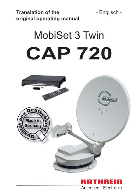
MobiSet 3 Twin<br />
- Englisch -<br />
<strong>CAP</strong> <strong>720</strong>
2<br />
GENERAL<br />
Dear Customer, Chère Cliente, Cher Client, Gentile cliente, Estimado cliente,<br />
GB<br />
You can obtain an English version of our installation instructions from our representatives in your country<br />
(http://www.kathrein.de/include/kontakte_groups_eng.cfm?kontinent=1&gruppe=SAT) or download one<br />
from our homepage (http://www.kathrein.de/en/sat/index.htm).<br />
F<br />
Vous pouvez obtenir un manuel d‘installation en français chez notre réprésentant en votre pays<br />
(http://www.kathrein.de/include/kontakte_groups_eng.cfm?kontinent=1&gruppe=SAT) ou le télécharger de<br />
notre page d‘ouverture (http://www.kathrein.de/en/sat/index.htm).<br />
I<br />
Lei puo avvere la versione italiana delle istruzioni di montaggio dalla nostra rapresentanza (http://www.<br />
kathrein.de/include/kontakte_groups_eng.cfm?kontinent=1&gruppe=SAT) piu vicina della sua citta´, oppure<br />
scaricarla dalla nostra hompage (http://www.kathrein.de/en/sat/index.htm)<br />
E<br />
Para obtener la versión española de nuestro manual de instalación, contacte nuestros representantes en<br />
su país (http://www.kathrein.de/include/kontakte_groups_eng.cfm?kontinent=1&gruppe=SAT) o bajela de<br />
nuestra página de Internet (http://www.kathrein.de/en/sat/index.htm).<br />
COMPANY ADDRESS AND ACCREDITED REPRESENTATIVE<br />
KATHREIN-Werke KG<br />
Anton-<strong>Kathrein</strong>-Straße 1 - 3<br />
P.O. Box 100 444<br />
83022 Rosenheim GERMANY<br />
Prof. Dr. Dr. h. c. <strong>Kathrein</strong>,<br />
MBA<br />
Personally liable<br />
Managing Director of KATHREIN-Werke KG
MOBISET 3 TWIN <strong>CAP</strong> <strong>720</strong> COMPONENTS/SCOPE OF DELIVERY<br />
1. Roof gland with retaining nut<br />
2. Mounting plate<br />
3. Turntable with integral controls<br />
4. Antenna carrier<br />
5. Parabolic refl ector<br />
6. Twin LNB<br />
SCOPE OF SUPPLY<br />
The MobiSet 3 Twin <strong>CAP</strong> <strong>720</strong> consists of:<br />
4<br />
UFS 940sw<br />
(Front view)<br />
See the UFS 940sw<br />
operating manual for a<br />
rear view of the receiver<br />
together with explanation<br />
of functions and operating<br />
instructions.<br />
• Turntable complete with control electronics, pre-assembled parabolic refl ector with LNB<br />
• Mounting plate<br />
• Complete cabling set with 8-m coax cable, 3-m coax cable and 10-m power supply cable for connection<br />
to the vehicle power supply<br />
• Roof gland with sealing gasket<br />
• Sikafl ex ® 291i adhesive sealant (100 ml tube)<br />
• UFS 940sw HDTV-DVB-S receiver with connecting cables, infrared sensor and infrared remote control<br />
• MobiSet 3 Twin <strong>CAP</strong> <strong>720</strong> installation and operating instructions<br />
• UFS 940sw satellite receiver operating manual<br />
5<br />
6<br />
3<br />
2<br />
1<br />
3
GENERAL ................................................................................................................................. 2<br />
MOBISET 3 TWIN <strong>CAP</strong> <strong>720</strong> COMPONENTS/SCOPE OF DELIVERY ............................................. 3<br />
CONTENTS ............................................................................................................................... 4<br />
PROPER USE ........................................................................................................................... 6<br />
SAFETY INSTRUCTIONS - IMPORTANT INFORMATION ............................................................. 7<br />
INSTALLATION AND CONNECTION ......................................................................................... 10<br />
INSTALLATION OF CABLE GLAND AND MOUNTING PLATE .......................................................... 12<br />
INSTALLATION OF TURNTABLE .............................................................................................. 15<br />
BRIEF INSTRUCTIONS FOR INSTALLING THE TURNTABLE ......................................................... 18<br />
INSTALLATION OF THE UFS 940SW ...................................................................................... 20<br />
LAYING CABLES AND CONNECTING THE TURNTABLE ............................................................... 25<br />
CONNECTING TO THE UFS 940SW ......................................................................................... 25<br />
FUNCTIONAL INSTRUCTIONS FOR CONNECTION TO THE ON-BOARD POWER SUPPLY .................. 26<br />
CONNECTION EXAMPLE FOR 12 V BATTERY CONNECTION ................................................. 27<br />
RECEPTION RANGE/FOOTPRINT ........................................................................................... 28<br />
DISMANTLING FOR SERVICING .............................................................................................. 29<br />
DISMANTLING ...................................................................................................................... 29<br />
ADDRESS OF THE SERVICE CENTRE ................................................................................... 29<br />
POLARISATION SETTING ....................................................................................................... 30<br />
POLARISATION SETTING ...................................................................................................... 30<br />
SAFETY NOTES .................................................................................................................... 32<br />
SETTING OPERATIONS ......................................................................................................... 32<br />
MANUAL LOWERING TO PARK POSITION .............................................................................. 35<br />
SAFETY INSTRUCTIONS ....................................................................................................... 35<br />
MANUAL LOWERING ............................................................................................................. 36<br />
TECHNICAL SPECIFICATION .................................................................................................. 37<br />
SIKAFLEX ® 291i SAFETY DATA SHEET .................................................................................. 40<br />
SIKAFLEX ® 291i TECHNICAL DATA SHEET ............................................................................ 45<br />
4<br />
CONTENTS (INSTALLATION MANUAL)
CONTENTS (OPERATING MANUAL)<br />
<strong>CAP</strong> <strong>720</strong> OPERATING MANUAL ............................................................................................... 47<br />
IMPORTANT INFORMATION FOR <strong>CAP</strong> <strong>720</strong> BEFORE SETUP .................................................... 48<br />
REMOTE CONTROL .............................................................................................................. 48<br />
FIRST INSTALLATION ............................................................................................................. 49<br />
<strong>CAP</strong> MENU (TURNTABLE ANTENNA SETTINGS) ..................................................................... 53<br />
CALLING UP THE <strong>CAP</strong> MENU ................................................................................................ 53<br />
RESETTING THE <strong>CAP</strong> SYSTEM (TURNTABLE ANTENNA) (RESET) ......................................... 53<br />
INPUTTING THE <strong>CAP</strong> GPS POSITION .................................................................................... 54<br />
TO MOVE THE ANTENNA MANUALLY .................................................................................... 54<br />
ELEVATION ......................................................................................................................... 55<br />
LNB TILT/SKEW ................................................................................................................... 55<br />
STOP ON SIGNAL ................................................................................................................ 55<br />
MOVE TO THE AZIMUTH (ROTATE THE ANTENNA) .................................................................... 55<br />
MOVE <strong>CAP</strong> TO PARK POSITION .............................................................................................. 56<br />
<strong>CAP</strong> SETTINGS ..................................................................................................................... 56<br />
ELEVATION BORDER AND ELEVATION OFFSET ........................................................................ 56<br />
SEARCH SPEED .................................................................................................................. 56<br />
ALIGNMENT (SATELLITE SEARCH) ........................................................................................ 57<br />
CHANNEL (SATELLITE) SELECTION/PROGRAMMING THE TIMER .......................................... 58<br />
CHANNEL SELECTION FROM THE CHANNEL LIST ................................................................ 58<br />
CHANNEL SELECTION FROM THE CHANNEL LIST (SORTED BY SATELLITE) ......................... 59<br />
CHANGE OF LOCATION.......................................................................................................... 60<br />
PARK ...................................................................................................................................... 61<br />
PARKING THE TURNTABLE ................................................................................................... 61<br />
SPECIAL MESSAGES FROM THE TURNTABLE ....................................................................... 62<br />
DECLARATION OF CONFORMITY ........................................................................................... 66<br />
DISPOSAL INSTRUCTIONS ..................................................................................................... 67<br />
5
6<br />
PROPER USE<br />
PROPER USE (USE FOR THE INTENDED PURPOSE)<br />
The MobiSet 3 Twin <strong>CAP</strong> <strong>720</strong> is designed to receive digital TV and radio programs via satellite.<br />
The automatic positioner is intended to be used as a turntable for the parabolic refl ector.<br />
The turntable can be used to receive digital TV and radio signals in the frequency range from 10.70 to<br />
12.75 GHz; the antenna cannot receive terrestrial signals (e.g. DVB-T).<br />
The turntable can only be used in conjunction with the UFS 940sw/740sw DVB-S receiver on the<br />
master cable.<br />
In conjunction with these receivers, the turntable provides fully automatic alignment of the parabolic<br />
refl ector to receive digital satellite signals. In addition, any conventional digital satellite receiver<br />
can be connected to the slave cable. The turntable is designed for use on stationary caravans or<br />
motor homes.<br />
Any use other than that specifi ed above will invalidate the warranty or guarantee.<br />
The following circumstances result in the loss of all warranty and liability claims towards<br />
the manufacturer:<br />
• Improper installation<br />
• Use of non-specifi ed mounting materials, which cannot guarantee the mechanical reliability of the<br />
antenna system<br />
• Impermissible use, e.g. use of the refl ector dish for storage<br />
• Structural changes or interference with the components and mounting accessories in the set, which<br />
could endanger both the mechanical and functional reliability<br />
• Improper or forcible opening of the components<br />
• Use of cleaners containing solvents, such as acetone, nitro-cellulose combination thinners, petrol etc.<br />
• Failure to observe installation and safety instructions in this manual<br />
Note: The maximum permissible speed for vehicles with a <strong>CAP</strong> <strong>720</strong> receiver unit mounted<br />
on the roof is 130 km/h. Before commencing a journey, the satellite dish must always be<br />
lowered into horizontal position (park position).<br />
The turntable may be operated in an ambient temperature range of -20 °C to +45 °C.<br />
Operating the system outside this range may result in malfunctions or damage to<br />
the system. When choosing the location for installation or raising the UFS 940sw,<br />
ensure there is adequate ventilation.<br />
The system may only be installed by qualifi ed specialist<br />
personnel!<br />
To prevent hazards during installation, operation or when driving on public highways, the<br />
instructions and information in this manual must be strictly adhered to. Proper installation<br />
and connection of the system are pre-requisites for conformity with the corresponding<br />
standards.<br />
This is documented in advance by the CE mark and the declaration of conformity in the<br />
appendix to this manual.
SAFETY INSTRUCTIONS - IMPORTANT INFORMATION<br />
Safety during installation work<br />
When carrying out installation work in locations where there is a risk of falling, take appropriate<br />
safety precautions, e.g. use of a working platform. Make sure that the vehicle roof is suffi ciently<br />
strong and stable to carry out the installation work (risk of damage or collapsing of roof).<br />
In case of doubt, contact a qualifi ed specialist dealer or the manufacturer of your vehicle to fi nd<br />
an appropriate installation location.<br />
Make sure that:<br />
- The turntable and connected units are disconnected from the power supply<br />
- The person carrying out the installation or repair does not suffer from vertigo and can move around<br />
safely on the roof of the caravan or motor home<br />
- The person carrying out the installation or repair is wearing sturdy and non-slip shoes<br />
- The person carrying out the installation or repair has a secure position to stand and hold on while<br />
working<br />
- The roof and the climbing equipment used (e.g. ladder) are dry, clean and non-slip<br />
- The roof can withstand the weight of the person carrying out the repairs<br />
Caution! Risk of death or injury due to falling or the roof collapsing!<br />
- Nobody should be inside the caravan/motor home underneath the antenna during dismantling/<br />
installation<br />
Caution! Risk of death or injury due to possible roof collapsing and falling parts!<br />
Proper installation and safety<br />
Essential information<br />
A crucial safety factor is proper performance of installation and electrical connection work, and the<br />
specifi ed alignment of the turntable in the direction of travel (park position), see also installation and<br />
connection.<br />
Comply as precisely as possible with the installation conditions and steps described.<br />
Modifi cations to the electrical installations in the vehicle should only be carried out by a specialist in<br />
vehicle electrics. Do not make any unauthorised changes to the turntable.<br />
Adhesive sealant<br />
The turntable is attached to the roof of the vehicle by adhesive and is secured by additional screws.<br />
Note that the curing of the adhesive sealant is temperature-dependent. It reaches its full strength only<br />
after approximately fi ve days.<br />
During installation work, comply strictly with the processing and safety instructions<br />
for the adhesive sealant (Sikafl ex ® 291i safety data sheet and Sikafl ex ® 291i technical<br />
data sheet).<br />
7
Road Traffi c Licensing Regulations (StVZO)<br />
The applicable regulations of the StVZO must be observed in respect of fi xed installation of the turntable on<br />
a vehicle which is driven on public highways.<br />
In particular, §§ 19/2; 30 C; 32 (2) and the EC directive 74/483 EEC are applicable.<br />
Briefl y, they state that no endorsement of the vehicle documentation is required unless the antenna unit<br />
causes the height of the laden vehicle to exceed 2 m, or the antenna unit projects beyond the outer lateral<br />
outline of the vehicle. The maximum permissible height of 4 m (vehicle and antenna unit) may not be<br />
exceeded.<br />
8<br />
SAFETY INSTRUCTIONS - IMPORTANT INFORMATION<br />
There is an increased risk of accidents if the normal vehicle height is increased by<br />
extending the antenna. The driver bears sole responsibility for the condition of the<br />
superstructure and external fi ttings!<br />
Cables<br />
Lay all cables such that nobody can tread on them or trip over them.<br />
To prevent parasitic induction or interference emissions, when extending the antenna cable use 75 Ω coaxial<br />
cable with a screening factor of at least 75 dB.<br />
If you tied the cables together with wire or similar materials, remove this to prevent<br />
the risk of fi re!<br />
When connecting the power cables (receiver and turntable) to the vehicle electrical supply, make sure that<br />
the cable polarity is not reversed.<br />
If the cable polarity is reversed there is a risk of thermal overload and damage to<br />
components when the equipment is powered up!<br />
Power supply, fusing<br />
Operate the system from your vehicle's battery (12 V) or a suitable mains power supply unit. This mains<br />
power supply unit must ensure a stable output voltage of 12 V, continuous current of 11 A and 15 A (300 ms)<br />
surge current.<br />
The peak current consumption is up to a maximum of 12 A.<br />
To ensure reliable functioning of the connection/control unit, the power supply cable must be connected<br />
directly to the battery. If the supply voltage is too low, the UFS 940sw receiver indicates this with the<br />
on-screen message “On-board voltage too low!” on the television screen.<br />
A 15 A fuse is incorporated in the power supply cable. If the fuse blows, rectify the source of the fault<br />
and replace the blown fuse with a fuse of the same rating (15 A).<br />
Never remove or bypass the fuse in the cable – cable fi re hazard!<br />
Connecting the power supply cable lead marked “Ignition” activates the turntable function for automatic<br />
lowering of the antenna. This lowering takes place as soon as the vehicle ignition circuit is turned on. When<br />
connecting the control unit to the vehicle power supply, make sure that the “+12V”, “Earth” and “Ignition”<br />
wires cannot be disconnected by intermediate switches, as this could deactivate the automatic lowering<br />
function.
SAFETY INSTRUCTIONS - IMPORTANT INFORMATION<br />
The antenna will be lowered within 12 seconds of the ignition being switched on<br />
(if the unit is in stand-by mode or the UFS 940sw is switched off). Otherwise the<br />
control unit that is in use is lowered immediately.<br />
Important: Lowering the antenna can take up to 30 seconds after the ignition is switched on and<br />
operates only if the turntable is connected to the 12-V power supply and to the ignition<br />
switch!<br />
Checks before commencing a journey<br />
• Before commencing a journey, the antenna must always be lowered into horizontal position (park<br />
position). If the antenna has collided with a fi xed or movable object, check that it is still securely<br />
attached.<br />
• As the antenna is subjected to vibration loads during driving, you should check at regular intervals,<br />
depending on the frequency of driving, that the system is still securely attached and tighten any parts<br />
that have worked loose.<br />
• The maximum permissible speed for vehicles with a receiver unit mounted on the roof and the antenna<br />
lowered is 130 km/h.<br />
• Lower the antenna if it will not be used for a long period. This makes the securing bolts more diffi cult<br />
to access (protection against theft).<br />
Antenna in the park position whilst driving<br />
The antenna must always be lowered into horizontal position (park position) while driving.<br />
As a reminder, attach the sticker from the supplementary sheet “Lower the <strong>CAP</strong> <strong>720</strong> antenna<br />
while driving” where it can easily be seen by the person operating the ignition switch.<br />
Safety precautions during operation<br />
During operation of the turntable, make sure that no persons, in particular children,<br />
are in the immediate vicinity of the turntable and that they cannot touch any<br />
moving parts – crush hazard!<br />
Always unplug the power supply during installation work.<br />
Exceeding the normal vehicle height by failing to lower the antenna increases the<br />
risk of accidents! The driver is responsible for the condition of external fi ttings<br />
on the vehicle!<br />
In addition the instructions in the installation and operating manuals for these<br />
devices and for the attachments and superstructures must be complied with at all<br />
times!<br />
If stormy weather is expected, the turntable must always be moved to the park<br />
position, otherwise both the <strong>CAP</strong> <strong>720</strong> and the vehicle may be damaged.<br />
9
REQUIRED TOOLS AND EQUIPMENT<br />
• Circular cutter, Ø 38 mm<br />
• Flat-bladed screwdriver for M5 screws<br />
• Power drill<br />
• Galvanised round head screws, depending on the roof structure (Ø: 5 mm, sheet metal screws D 7981,<br />
depending on the roof structure) or round head screws D 7985 with washers and nuts<br />
• Twist drill, Ø 2.5 or 5.5 mm<br />
• Round fi le and/or emery paper<br />
• Cleaning agent<br />
• Open-ended or ring spanners 10 and 11 mm across fl ats<br />
• Knife<br />
• Cross-head screwdrivers for M3 and M5 screws<br />
• Torque wrench capacity 6 to 11 Nm<br />
• Hexagon socket key (5 mm)<br />
• Two wooden beams for supporting the turntable<br />
UNPACKING AND PREPARATION<br />
10<br />
INSTALLATION AND CONNECTION<br />
The <strong>CAP</strong> <strong>720</strong> must not be carried on the satellite<br />
dish, since this can cause the dish to distort. Keep<br />
the <strong>CAP</strong> <strong>720</strong> in its cardboard box for transport on<br />
to the vehicle roof.<br />
Retain the original packaging, as if it is necessary<br />
to send the unit for repair transport damage cannot<br />
be ruled out and the manufacturer accepts no<br />
liability for possible damage.<br />
Loosen the six fastening screws (width A/F:<br />
10 mm). Carefully lift the turntable off the mounting<br />
plate and place it on the prepared wooden<br />
supports. Make sure that the cables are not<br />
crushed where they emerge from the underside of<br />
the turntable.<br />
SELECTING THE INSTALLATION LOCATION<br />
Essentially, the cable lengths of the MobiSet 3 Twin <strong>CAP</strong> <strong>720</strong> components allow you a free choice of<br />
installation location on your caravan or motor home.<br />
However, you should take note of the following points:<br />
The <strong>CAP</strong> <strong>720</strong> packaging can be opened along<br />
both long sides. This allows easier access to the<br />
fastening screws.<br />
• Before installation, you should fi nd out whether the operating manual for your vehicle permits the fi tting<br />
of non-vehicle-specifi c parts or what requirements need to be met in order to do so.<br />
• For direct satellite reception, there should be no obstructions between the antenna and the satellite.<br />
Therefore, make sure that the antenna is not shadowed by roof extensions such as luggage racks,<br />
air conditioning units, solar panels, etc. The problem of shadowing applies also to the selection of the<br />
parking place for your vehicle. For interference-free satellite reception, the antenna needs a projected<br />
free view to the South at an angle of between 0° and 75° (depending on location) to the horizontal.
• When selecting the installation position, take into account the range of movement of the turntable<br />
(see graphics and the “Technical Data” chapter). There must be no structures on the roof that would<br />
obstruct this range of movement (risk of collision). For safety, keep at least the required area free<br />
(for ease of installation and any subsequent dismantling).<br />
Recommended<br />
clear space<br />
(radius) at least<br />
807 mm<br />
Elevation max. 75°<br />
Roof attachments<br />
may be mounted<br />
within the hatched<br />
area.<br />
INSTALLATION AND CONNECTION<br />
Elevation 45°<br />
The height of neighbouring<br />
attachments on the roof may<br />
lead to shadowing!<br />
Direction of travel<br />
Park<br />
position<br />
Zone (radius min.<br />
566 mm) within which<br />
a device with a height<br />
of up to 230 mm can<br />
be attached next to the<br />
turntable<br />
11
• Choose an installation position on the roof that is as horizontal as possible or only slightly sloping,<br />
depending on the location of the vehicle, since roof inclinations greater than 5° may lead to problems<br />
when searching for the satellite.<br />
• To ensure secure adhesion, the height difference of the roof curve may not be more than 1 cm over a<br />
length of 2 m, as otherwise the gap between the roof and the mounting plate would be too great to be<br />
fi lled by the adhesive sealant.<br />
• As the vehicle is constantly subjected to vibration loads during travel, the roof below the antenna unit<br />
is also subject to signifi cant loads. Please note given the nature and capacity of your vehicle roof<br />
(see also operating manual for the vehicle) that the weight of the antenna unit is approx. 9.7 kg.<br />
In case of doubt, consult a qualifi ed dealer or your vehicle’s manufacturer.<br />
• The roof gland provides a watertight seal through which the three connecting cables (coax cable and<br />
power supply cable) are fed into the interior of the vehicle directly underneath the turntable. If you<br />
prefer a different method of laying the cables, they can be run from the rear of the turntable via the<br />
channel provided in the mounting plate. The cables must then be run along the roof of the vehicle<br />
in a protective cable duct and through a separate HDZ 100 roof gland (neither supplied).<br />
• The HDZ 100 roof gland is available as an accessory under part number 20410032 from specialist<br />
dealers.<br />
Note: Do not cut the cables short, as otherwise the proper functioning of the unit can no longer be<br />
guaranteed.<br />
INSTALLATION STEPS<br />
INSTALLATION OF CABLE GLAND AND MOUNTING PLATE<br />
Note: If you had previously used a <strong>Kathrein</strong> HDM140/141 fl exible satellite mast or another mast<br />
with a diameter of 34 mm, you can continue using the existing gland hole in the roof<br />
(if space allows).<br />
Figure: A<br />
• In the centre of the intended position of the turntable, drill the opening for the cable gland with a circular<br />
cutter (Ø: 38 mm). Deburr the hole with a round fi le or emery paper.<br />
• Provisionally insert the roof gland into the drilled hole (Fig. A).<br />
12<br />
INSTALLATION AND CONNECTION<br />
O Ring Adhesive
Figure: B<br />
INSTALLATION AND CONNECTION<br />
• Place the mounting plate on the roof of the vehicle, such that the centre hole is positioned centrally to<br />
the cable gland. The arrow symbol must be visible from above and point forwards in the direction of<br />
travel (Fig. B).<br />
• Mark out the positions of the six fastening holes on the roof of the vehicle in a circular pattern.<br />
Note: The size of the holes and the choice of fastening screws to be used (not supplied) depend<br />
on the type and thickness of the materials used in the roof structure. If the roof panelling<br />
(plastic roofs) is suffi ciently strong, it is recommended that round head screws, plain<br />
washers and self-locking nuts are always used to secure the glued mounting plate.<br />
• For very thin roof panel materials and insuffi cient support in the insulating material, through holes<br />
(Ø: 5.5 mm) into the interior of the vehicle are necessary; galvanised M5 round head screws of<br />
suffi cient length should then be used.<br />
Make sure that you use a suffi ciently strong support that can accept the screw tensile forces (large<br />
plain washers or a complete reinforcing plate).<br />
Figure: C<br />
*) Not included<br />
Arrow in the<br />
direction of travel<br />
2.5–3<br />
Adhesive area<br />
between the<br />
two grooves<br />
5.5<br />
Washer<br />
Alternative<br />
roof attachment<br />
13
• Create the holes necessary to secure the mounting plate (Fig. C).<br />
• In addition to the screwed connection, the mounting plate and roof gland must be bonded to the roof with<br />
adhesive and sealed. This is done using the Sikafl ex® 291i adhesive sealant supplied, which is ideally<br />
suited for this purpose thanks to its broad range of adhesion.<br />
Before starting to use Sikafl ex® 291i adhesive sealant, be sure to read the Sikafl ex® Products safety<br />
data sheet and technical data sheet in this installation manual!<br />
The prerequisite for good adhesive characteristics is a clean, dry and grease-free substrate. You should<br />
therefore clean the roof surface with a suitable cleaning agent within a circumference of 35 cm around the<br />
drilled hole and allow the surface to dry thoroughly.<br />
If the surface is painted, ensure that the paint fi nish is suffi ciently well bonded to the substrate.<br />
If the coat of paint is already loose or peeling, it must be removed down to a stable layer in the area to<br />
which the adhesive will bond. If you have any doubts concerning the adhesive characteristics, consult a<br />
paint and lacquer specialist, or the manufacturer of your vehicle.<br />
Under certain circumstances, it may be necessary for you to improve the adhesive properties of the roof<br />
surface by pre-treatment with a cleaning agent available from specialist dealers (e.g. Sika® Cleaner) or a<br />
primer (e.g. Sika® Primer).<br />
The procedure for gluing the mounting plate is as follows:<br />
Figure: D<br />
14<br />
INSTALLATION AND CONNECTION<br />
Recess<br />
for cable<br />
Adhesive areas between<br />
the two grooves
• Ensure before starting adhesive work that the temperature of materials to be glued and the adhesive<br />
sealant is between +5 °C and +40 °C. Prepare all necessary fasteners and tools.<br />
• Prepare the tube of adhesive sealant in accordance with the instructions enclosed with the tube.<br />
• Remove the roof gland (Fig. A) and apply the adhesive sealant evenly to the underside of the roof gland<br />
fl ange.<br />
Replace the roof gland in the drilled hole and press it fi rmly against the roof of the vehicle.<br />
• Apply the adhesive sealant evenly to the underside of the mounting plate, completely covering the area<br />
within the circular groove (Fig. D).<br />
This area of the vehicle roof must be completely coated with adhesive in order to achieve the necessary<br />
bonding force.<br />
Place the mounting plate on the roof of the vehicle, as you did previously when marking out the drilled<br />
holes.<br />
Make sure that the arrow on the mounting plate points forward in the direction of travel.<br />
The fastening holes must be perfectly aligned with the prepared holes in the roof.<br />
• Fasten the mounting plate in place with the prepared screws, evenly tightening six screws across the<br />
diagonals.<br />
Note: The adhesive sealant used is capable of fi lling small gaps caused by the curvature of the<br />
vehicle's roof. However, you should ensure that the mounting plate is not bent by tightening<br />
the screws.<br />
• Remove any adhesive sealant that leaks out at the sides with a clean cloth or if necessary with<br />
Sikafl ex® Remover (available from specialist dealers). Do not use cleaning agents or thinners<br />
containing solvents, as this could damage the adhesive sealant applied under the mounting plate.<br />
Use only cleansing paste and water to clean your hands.<br />
• Secure the cable gland from inside the vehicle by tightening the ribbed nut supplied (Fig. A).<br />
• Note that the curing of the adhesive sealant depends on the ambient temperature and the humidity.<br />
Final strength is reached only after approx. fi ve days. However, this need not restrict further<br />
installation work, since the mounting plate is held in place by the tightened screws.<br />
INSTALLATION OF TURNTABLE<br />
INSTALLATION AND CONNECTION<br />
VARIANT WITH CABLE GLAND UNDERNEATH THE TURNTABLE<br />
• Feed the ends of the cables with the connectors as far as possible through the cable gland into the<br />
interior of the vehicle.<br />
15
Figure: E<br />
16<br />
INSTALLATION AND CONNECTION<br />
Gasket with plug for<br />
the unused duct<br />
Direction of travel<br />
Battery, ignition<br />
Receivers<br />
• Lift up the turntable and place it carefully on the mounting plate facing in the direction of travel<br />
(see illustration Fig. E) (do not step on the plug connector and do not kink/crush the cables!).<br />
The through holes on the turntable must be perfectly aligned with the threaded holes on the mounting<br />
plate. When lowering, make sure that the cables are fed through the cable gland and are not crushed.<br />
• Apply a little adhesive sealant to the six threaded holes in the mounting plate and screw the fastening<br />
screws into the thread. Tighten the screws to a torque of 6 Nm.<br />
• To prevent water vapour from inside the vehicle reaching the turntable through the roof gland, thread the<br />
three cables through the sealing gasket supplied (see Fig. E) and insert this into the roof gland until it<br />
reaches the stop. Make sure that no tensile load is acting downwards on the sealing gasket as this can<br />
cause it to fall out in the course of time.
INSTALLATION AND CONNECTION<br />
VERSION WITH EXTERNAL CABLE GLAND (FIG. F)<br />
Direction of travel<br />
Cables laid in the<br />
cable duct * )<br />
and water-tight<br />
roof gland * )<br />
*) Not included! The HDZ 100 roof gland is available as an accessory under part number 20410032<br />
from specialist dealers.<br />
• The external roof gland is arranged so that it forms a water-tight enclosure on the vehicle roof around the<br />
point where the three cables projecting from the turntable are connected to the extension cables within<br />
the interior of the vehicle, and where if necessary they can be disconnected.<br />
• Arrange the cables in the cable duct when placing the turntable on to the mounting plate. Make sure<br />
that the cables are not crossed over and that they are taut so that they cannot be crushed. Do not<br />
try to pull the cables from the unit. This could damage the cables or loosen the cable connections.<br />
• Place the turntable carefully on the mounting plate. The through holes on the turntable must be<br />
perfectly aligned with the threaded holes on the mounting plate.<br />
• Apply a little adhesive sealant to the six threaded holes in the mounting plate and screw the fastening<br />
screws into the thread. Tighten the screws to a torque of 6 Nm.<br />
• When feeding the cables through the HDZ 100 roof gland, make sure they are not crushed, kinked or<br />
damaged.<br />
17
18<br />
INSTALLATION AND CONNECTION<br />
BRIEF INSTRUCTIONS FOR INSTALLING THE TURNTABLE<br />
The sequence of pictures shown illustrates all the necessary installation steps<br />
that are required to install the turntable and the parabolic refl ector on the roof of<br />
the vehicle.<br />
The other detailed instructions in this installation and operating manual must also be followed!<br />
Determination of installation location.<br />
Important! System has a turning<br />
range of 162 cm (Ø). Drill hole with<br />
Ø 38 mm. Deburr sharp edges of<br />
hole.<br />
Unscrew screws (x 6, 10 AF) from<br />
the mounting plate and remove<br />
the mounting plate.<br />
Apply Sikafl ex® 291i adhesive to<br />
the spigot of the roof gland. Insert<br />
the spigot into the hole and secure<br />
it from below with the knurled nut.<br />
Place the turntable on prepared<br />
wooden supports to protect the<br />
roof of the vehicle.
Align mounting plate. Arrow in the<br />
direction of travel. Mark out the six<br />
holes for securing the mounting<br />
plate.<br />
Place mounting plate on roof<br />
gland and secure with appropriate<br />
screws (choose screws according<br />
to thickness/structure of roof).<br />
INSTALLATION AND CONNECTION<br />
Apply Sikafl ex® 291i adhesive in<br />
a sinuous line between the two<br />
grooves and spread with spatula<br />
or similar. Avoid skin contact!<br />
Screw turntable on to mounting plate using torque<br />
wrench.<br />
Important!<br />
Tightening torque: 6 Nm<br />
Set up electrical connections. Connect the UFS 940 receiver. Connect the turntable to the battery.<br />
The antenna must always be lowered into horizontal position (park position) while<br />
driving!<br />
Maximum driving speed of the vehicle: 130 km/h<br />
19
INSTALLATION OF THE UFS 940SW<br />
The four screw sockets provided (see diagram on the next page) allow you to install the receiver not<br />
only resting on a shelf but also to fi x it there or in other positions.<br />
20<br />
INSTALLATION AND CONNECTION<br />
SELECTION OF A SUITABLE INSTALLATION LOCATION<br />
Note: When choosing the installation location, bear in mind that the rear of the unit should always<br />
be accessible. The UFS 940sw is equipped with a power saving circuit and a separate<br />
infrared transmitter, which means that the unit does not need to be placed where it is visible.<br />
You can therefore fi t the UFS 940sw out of sight in any location, e.g. on cupboard walls,<br />
side walls or the base of storage compartments.<br />
In addition, the following points should be taken into account:<br />
• The wall thickness at the installation location must be at least 15 mm, as otherwise the screws will<br />
break through on the other side or damage the surface<br />
• Ensure that the cupboard or storage compartment in which the unit is housed is adequately ventilated,<br />
to prevent a build up of heat. Carpet-covered walls are unsuitable for installation<br />
• Take care when tightening the screws not to damage any cables etc. behind or in the wall<br />
• The receiver is designed for installation in exclusively dry, interior locations. The installation location<br />
must be protected against moisture<br />
• The cable lengths must be taken into account when choosing the installation location<br />
• The connecting cables must be provided with strain reliefs<br />
Ventilation:<br />
The heat generated within the receiver can<br />
be dissipated from the following sides of the<br />
casing: Bottom, left, right and top. When<br />
selecting the installation location, make<br />
sure that these sides are not obstructed or<br />
covered. If the unit is operated continuously<br />
with insuffi cient ventilation, this can<br />
negatively affect the length of its working<br />
life!<br />
Maintain a clearance of at least 20 cm<br />
above or below the unit, 2 cm to either<br />
side and 5 cm behind it, to allow<br />
unobstructed dissipation of the heat<br />
generated.<br />
20 cm<br />
2 cm<br />
Minimum<br />
clearance<br />
5 cm<br />
5 cm<br />
2 cm<br />
The unit monitors its temperature in operation. Premature failure of the unit<br />
due to continuous operation at temperatures higher than the recommended<br />
operating temperature as a result of insuffi cient ventilation does not constitute<br />
grounds for a claim under warranty/guarantee.
PREPARATIONS<br />
Removing the blanking plugs:<br />
When the unit is delivered, the screw<br />
sockets are covered with blanking plugs.<br />
These can be pushed out, using the<br />
screws supplied (working upwards from<br />
below, see diagram on the right).<br />
Attaching the infra-red sensor:<br />
If the unit is installed in open view, you<br />
can attach the infra-red sensor directly to<br />
the unit; or if the receiver is installed in a<br />
concealed location, you should position<br />
the infra-red sensor where it can be clearly<br />
seen by the remote control unit. There<br />
are three places on the infra-red sensor<br />
where the adhesive strips supplied can<br />
be attached (see diagram on the right ,<br />
and ). The attachment point is<br />
provided for sticking the infra-red sensor<br />
directly to the unit.<br />
INSTALLATION AND CONNECTION<br />
Connections and fusing of the unit:<br />
All connection cables for connection to the receiver (including the infra-red sensor) are connected at the<br />
rear of the unit (see also the item “Connection example” in this section). When selecting the installation<br />
location, allow suffi cient clearance at the rear of the unit for these cables and their plugs.<br />
On the left hand side of the receiver viewed from the front there is a fuse inserted from the outside.<br />
This fuse (for the type, see the section “Important Information” in the receiver operating manual) should<br />
be accessible even after the unit has been installed, so that it can easily be exchanged if required.<br />
The attachment point on the receiver is<br />
on the front panel (see diagram on the<br />
right ).<br />
<br />
<br />
<br />
<br />
<br />
21
Using the adhesive strips supplied, now<br />
install the infra-red sensor either on the<br />
receiver or at the chosen location. If the<br />
infra-red sensor is installed on the unit,<br />
its cable can be threaded in at its base,<br />
as for a phone, and routed to the rear of<br />
the receiver (see diagram on the right).<br />
22<br />
INSTALLATION AND CONNECTION<br />
When threading in the<br />
cable, take care not to<br />
damage its sheath.<br />
IMPORTANT INSTRUCTIONS FOR INSTALLATION<br />
Under no circumstances use countersunk-head screws for<br />
installation (see diagram on the right), since these can damage the<br />
screw sockets on the receiver. Wherever possible, use the wood<br />
screws supplied with the receiver.<br />
Before installing the receiver so that it is attached to another piece<br />
of equipment (such as a TV set), check with the manufacturer of that<br />
equipment or by reference to the documentation supplied with it<br />
whether this is permissible, and if so what fi ttings (screws etc.) you<br />
need/can use for this. The temperature rise of each of the units in<br />
operation (receiver/TV set) can in some circumstances affect the other unit.<br />
The wood screws supplied with the receiver should not under any circumstances<br />
be used to attach it to a TV set or other electrical equipment! This could damage<br />
that equipment, possibly beyond repair.<br />
Risk of fatal injury due to electric shock!<br />
Use of other screws:<br />
If because of the installation location or<br />
factors associated with it, the screws<br />
supplied cannot be used, refer to the<br />
diagram alongside when selecting the<br />
screws to be used. This shows you the<br />
cross-section area of the screw sockets<br />
on the receiver and shows which screws<br />
(diameter, screw head profi les etc.) can<br />
be inserted into the receiver support.<br />
6.6
INSTALLATION AND CONNECTION<br />
Useful information for installing the receiver on a TV set:<br />
For installation by attachment to the rear of a TV set, securing with two screws is suffi cient.<br />
The equipment must have one of the following hole patterns (for wall mounting) on its rear panel:<br />
100 x 100; 100 x 200; 200 x 200 or 200 x 400. If this is not the case, a VESA adaptor plate can be<br />
obtained from a specialist dealer.<br />
Before installing the receiver it is essential you read the section “Wall mounting” (or the equivalent)<br />
in the user instructions for your TV set. This will tell you the screw diameters (M4, M6 or M8) and most<br />
importantly the permissible screw penetration depth.<br />
Before starting any installation work, it is essential you disconnect all the units<br />
concerned from the mains. If the screws penetrate too deeply into the TV set<br />
they may damage it beyond repair and create the risk of a fatal electric shock!<br />
Under no circumstances install the receiver between the TV and a wall support!<br />
Installation on the rear panel of a TV set is permissible only if the TV set is<br />
resting on a stand that is attached in some other way.<br />
Marking out the screw/drill points at the installation location:<br />
This diagram is to assist you in marking out the exact screw/drill points at the installation location.<br />
↑<br />
Rear of the receiver<br />
Front of the receiver<br />
↓<br />
23
INSTALLATION<br />
24<br />
INSTALLATION AND CONNECTION<br />
Secure the receiver at the installation location previously selected and prepared.<br />
Do not force it, and take care not to damage either the screw sockets, the receiver<br />
casing itself or any cables that are already attached to the receiver!<br />
Screw projection<br />
Example shown for mounting on wood
• Lay the master coaxial cable (marked red) to the UFS 940sw and the second coaxial cable to the second<br />
receiver. If you are not using a second receiver, we recommend that you lay the second coaxial cable in<br />
any case, so that it is available should you ever need it.<br />
• Lay the turntable power supply cable (3-pin plug) to the battery.<br />
Avoid laying the cables across sharp edges and secure the cables against possible chafi ng points.<br />
• Connect the Master coaxial cable (coming from the turntable) to the “IF IN” F socket on the rear of the<br />
UFS 940sw.<br />
• Place the infrared sensor for the receiver close to or directly on top of the TV set and lay the cable to<br />
the UFS 940sw. Connect the 6-pin Western connector at the rear to the socket marked “IR REMOTE IN”<br />
(see also “Installation of the UFS 940sw receiver” in this section).<br />
Note: Lay the Cinch cable supplied with the <strong>CAP</strong> <strong>720</strong>. Take great care to plug the cable into the<br />
correct socket!<br />
CONNECTING TO THE UFS 940SW<br />
INSTALLATION AND CONNECTION<br />
LAYING CABLES AND CONNECTING THE TURNTABLE<br />
The receiver must be connected to no other power supply than 12 V DC.<br />
The receiver’s earth connection must be connected to the negative pole of the<br />
motor home or caravan battery.<br />
Isolate the on-board power supply (master switch “off” or disconnect the positive pole of the on-board<br />
power supply battery) before commencing the following work:<br />
• Connect the power cable supplied (depending on the power supply available in your motor home or<br />
caravan, either a 12 V supply or a 230 V supply via a power supply unit) to the “ ” socket<br />
on the receiver.<br />
Make sure that the “inline” integrated fuse (5 A) of the cable is fully plugged in and is intact. If the fuse<br />
blows, the source of the fault must fi rst be eliminated. The fuse must only ever be replaced by a fuse<br />
with the same rating (5 A).<br />
The fuses in the cable and in the receiver must never be by-passed – cable fi re hazard!<br />
• At the connecting point for the power cable, the voltage must not fall below 10.9 V even with a load<br />
of 12 A. Otherwise optimum functioning can no longer be guaranteed.<br />
• Connect the power cable to the respective socket in your motor home or caravan (12 V or 230 V).<br />
25
26<br />
INSTALLATION AND CONNECTION<br />
Only for connection in a motor home, not in a caravan!<br />
• The green connecting cable, marked “IGNITION” allows you the option of connection to a circuit in<br />
the vehicle that is activated when the ignition key is turned and then carries a continuous 12 V supply.<br />
This type of connection ensures that when the engine is started the antenna is automatically lowered<br />
into the park position (the receiver does not need to be turned on).<br />
Note that the antenna can then be lowered only when the power supply is present at the turntable<br />
in addition to the ignition signal!<br />
• Check the connections before you re-connect the on-board power supply.<br />
• For commissioning and more detailed information on additional operator functions, we refer you to the<br />
separate operating manual enclosed.<br />
FUNCTIONAL INSTRUCTIONS FOR CONNECTION TO THE ON-BOARD POWER SUPPLY<br />
Under certain circumstances, problems can arise when the units are connected to different connecting<br />
sockets or circuits/earth potentials. If no others are available, it is recommended that you connect<br />
the connecting sockets for receiver and TV set to the same cable, as shown in Figure “G”. The current<br />
rating of the circuit used must be checked with respect to the intended application.<br />
Further information on operating the UFS 940sw receiver can be found in the operating manual supplied<br />
with the unit.
Figure: G<br />
Important:<br />
For operation with two batteries, it<br />
must be ensured that the ignition<br />
signal earth has the same potential<br />
as the power supply battery earth<br />
for the turntable.<br />
Non-compliance means that the<br />
automatic lowering function will not<br />
work!<br />
Ensure the cable polarity is correct!<br />
INSTALLATION AND CONNECTION<br />
CONNECTION EXAMPLE FOR 12 V BATTERY CONNECTION<br />
external<br />
IR sensor<br />
TV set<br />
Not included<br />
Master<br />
6-pin<br />
Cigarette lighter<br />
socket or 12V<br />
DIN ISO 4165<br />
standard socket<br />
Battery<br />
brown white green<br />
Battery<br />
Ignition<br />
HDMI cable recommended for<br />
HDMI-capable TV set<br />
The second receiver can be used<br />
to receive channels only from the<br />
satellite currently selected on the<br />
fi rst receiver. There is no restriction<br />
on choice of channels from<br />
the selected satellite. The second<br />
receiver must be confi gured as a<br />
„Simple LNB“ in the fi rst installation<br />
menu!<br />
27
28<br />
RECEPTION RANGE/FOOTPRINT<br />
The footprint is the reception area on the earth that a satellite covers with its transmission beam (spot),<br />
within which satellite reception is possible. The transmission power is at its greatest in the centre of this<br />
spot – it becomes progressively weaker moving outwards.<br />
You should preferably align your antenna to the position of the ASTRA satellite 19.2° East (picture<br />
below left), EUTELSAT/HOTBIRD 13° East (picture below right). The spots for these satellites are<br />
shown below.<br />
The inner line of the<br />
footprint here shows<br />
the area covered by the<br />
digital signals from the<br />
ASTRA satellite.<br />
The outer dashed<br />
line of the footprint<br />
displayed here shows<br />
the area that is covered<br />
by individual ASTRA<br />
satellite. Therefore<br />
not all channels are<br />
available within this<br />
footprint.<br />
The satellites broadcast the various channel packages in different<br />
footprints. The respective channel packages can normally be received<br />
within these footprint zones. In the marginal zones, reception is possible,<br />
although because of a variety of infl uencing factors this cannot be<br />
guaranteed. The quality of the channels received can vary considerably<br />
(for instance due to environmental factors).
If repairs to the system or individual components are necessary, contact your specialist dealer or our<br />
service centre (see below for address).<br />
DISMANTLING<br />
• The cables laid within the vehicle can remain there<br />
• Unscrew the six M6 screws securing the turntable to the mounting plate<br />
• Place two wooden supports on the vehicle roof, for protection<br />
• Then place the turntable on the prepared wooden supports<br />
• To ship the turntable, use the original packaging which you have saved<br />
• Seal the opening in the vehicle roof appropriately to protect against the ingress of moisture<br />
• If a HDZ 100 roof gland has been fi tted and the equipment is then removed, the cable channels<br />
no longer used should be sealed with the integral plugs. The enclosure is then watertight once again.<br />
Note: Before exchanging the UFS 940sw, the turntable must fi rst be moved to the park position.<br />
ESC<br />
Electronic Service Chiemgau GmbH<br />
Bahnhofstraße 108<br />
83224 Grassau GERMANY<br />
Tel: +49 8641 9545-0<br />
Fax: +49 8641 9545-35 and -36<br />
Internet: http://www.esc-kathrein.de<br />
E-Mail: service@esc-kathrein.de<br />
DISMANTLING FOR SERVICING<br />
Never open the turntable yourself!<br />
Do not cut the cables! At the cable junction provided, disconnect the cables<br />
projecting from the turntable from the two cables laid within the interior of the<br />
vehicle (unplug the plug).<br />
ADDRESS OF THE SERVICE CENTRE<br />
Factory repair centre Regional repair centre<br />
KATHREIN Sachsen GmbH<br />
Lindenstraße 3<br />
09241 Mühlau GERMANY<br />
Tel: +49 3722 6073-31<br />
Fax: +49 3722 6073-18<br />
E-Mail: service@kathrein-sachsen.de<br />
29
POLARISATION SETTING<br />
30<br />
POLARISATION SETTING<br />
The LNB for the <strong>CAP</strong> <strong>720</strong> is factory-set to the polarisation setting “0”. In this position<br />
you can still receive signals from satellites with differences (between the longitude of the<br />
desired reception area and the orbit position of the satellite) of 15° to 20°. For differences<br />
greater than this it is best to rotate the LNB and set the necessary polarisation angle.<br />
However, we expressly draw attention to the fact that positioning the LNB at a<br />
deviation of up to +45° or up to -45° from the centre position makes sense only if a<br />
satellite to the far West or the far East is actually preferred for reception.<br />
The respective setting angle required for the polarisation can be found in the following table.<br />
Longitude for the reception position
Satelliten/Satellites/Satellites<br />
Hispasat<br />
1C/1D<br />
30°<br />
West<br />
West/Ouest<br />
Atlantic<br />
Bird 2/<br />
Telecom 2D<br />
8°<br />
West<br />
West/Ouest<br />
Atlantic<br />
Bird 3<br />
5°<br />
West<br />
West/Ouest<br />
Thor 2/3<br />
0.8°<br />
West<br />
West/Ouest<br />
EUTELSAT<br />
W3A<br />
7°<br />
Ost<br />
East/Est<br />
EUTELSAT<br />
W1<br />
10°<br />
Ost<br />
East/Est<br />
HOTBIRD<br />
13°<br />
Ost<br />
East/Est<br />
EUTELSAT<br />
W2<br />
16°<br />
Ost<br />
East/Est<br />
ASTRA<br />
19.2°<br />
Ost<br />
East/Est<br />
ASTRA<br />
(Eurobird 1)<br />
28.2°<br />
Ost<br />
East/Est<br />
TÜRKSAT<br />
42° Ost<br />
East/Est<br />
Land/Country/Pays<br />
Albanien/Albania/L´Albanie -23 -2 8 5 8 11 15 22 26 28/16 41<br />
Belgien/Belgium/La Belgique -27 -11 -5 -9 -7 -5 -2 4 8 10/-2 25<br />
Bulgarien/Bulgaria/Bulgarie -17 4 14 10 13 16 19 25 29 31/19 41<br />
Dänemark/Denmark/Danemark -19 -4 2 -3 -1 1 3 8 11 ´13/1 24<br />
Deutschland/Germany/Allemagne -23 -7 0 -4 -2 0 3 9 12 14´/2 28<br />
Frankreich/France/France -32 -16 -9 -13 -10 -7 -5 3 7 10/-2 27<br />
Finnland/Finland/Finlande -7 6 10 5 6 7 9 12 14 15´/3 21<br />
Griechenland/Greece/Grèce -21 2 14 11 14 18 21 28 32 34/22 46<br />
Großbritannien/Great Britain/<br />
-26 -13 -8 -13 -11 -9 -7 -2 1 3/-9 17<br />
La Grande-Bretagne<br />
Italien/Italy/L´Italie -29 -10 -1 -4 -1 3 6 15 19 ´22/10 37<br />
Irland/Ireland/L´Irlande -30 -17 -12 -17 -15 -13 -11 -6 -3 0/12 15<br />
Kroatien/Croatia/Croatie -24 -5 4 1 4 7 10 17 20 ´23/11 36<br />
Liechtenstein/Liechtenstein/<br />
-26 -10 -2 -6 -3 0 2 10 13 `16/4 31<br />
Liechtenstein<br />
Luxemburg/Luxemburg/Luxembourg -26 -11 -4 -8 -6 -3 -1 6 9 12/0 26<br />
Monaco/Monaco/Monaco -31 -13 -5 -9 -6 -3 0 9 13 ´16/4 32<br />
Niederlande/Netherlands/<br />
-25 -10 -4 -8 -6 -4 -1 5 8 10/-2 24<br />
Les Pays-Bas<br />
Norwegen/Norway/Norvège -11 2 6 1 2 4 5 9 10 12/0 19<br />
Österreich/Austria/L´Autriche -24 -6 2 -2 0 3 6 13 16 ´18/6 32<br />
Polen/Poland/Pologne -17 0 7 2 5 7 9 15 18 ´20/8 31<br />
Portugal/Portugal/Portugal -43 -28 -22 -26 -23 -20 -17 -8 -3 0/-12 24<br />
Rumänien/Romania/Roumanie -16 4 13 9 11 14 17 23 26 28/16 38<br />
Schweden/Sweden/Suède -12 1 6 1 2 4 5 9 11 ´13/1 21<br />
Schweiz/Switzerland/Suisse -28 -11 -3 -7 -5 -2 1 8 12 ´15/§ 30<br />
Serbien-Montenegro/Serbia and<br />
-21 -1 9 5 8 11 14 21 24 26/14 39<br />
Montenegro/Serbie-Monténégro<br />
Slowakei/Slovakia/Slovaquie -18 0 7 3 6 8 11 17 20 ´22/10 34<br />
Slowenien/Slovenia/Slovénie -24 -5 3 -1 2 5 8 15 18 ´21/9 34<br />
Spanien/Spain/L´Espagne -40 -24 -17 -21 -18 -15 -11 -2 3 ´6/5 29<br />
Tschechien/Czech Republic/<br />
-21 -4 4 0 2 5 7 13 16 ´19/7 31<br />
Republique Tchéque<br />
Ungarn/Hungary/La Hongrie -20 -1 7 3 6 9 11 18 21 ´23/11 35<br />
Other countries and towns in these countries can be found on the Internet on the <strong>Kathrein</strong> Home Page under “www.kathrein.de/en/sat/index.htm” menu item<br />
“Satellite and terrestrial antenna systems/Technical Information/Azimuth/Elevation”.<br />
31
SAFETY NOTES<br />
32<br />
POLARISATION SETTING<br />
We strongly advise that users who are not familiar with the setting operations should not<br />
undertake to set the LNB themselves. They should contact a technician or engineer. They may<br />
fi nd a suitable person on the campsite.<br />
Make sure that:<br />
- The antenna and connected units are disconnected from the power<br />
- The person carrying out the installation does not suffer from vertigo and can move around safely on the<br />
roof of the caravan or motor home<br />
- The person carrying out the settings is wearing sturdy and non-slip shoes<br />
- The person carrying out the settings has a secure position to stand and hold on while working<br />
- The roof and the climbing equipment used (e.g. ladder) are dry, clean and non-slip<br />
- The roof can withstand the weight of the person carrying out the settings<br />
Caution! Risk of death or injury due to falling or roof collapsing!<br />
- During setting operations, make sure that no persons, in particular no children, are in the immediate<br />
vicinity of the turntable and that they cannot touch any moving parts - crush hazard! Nobody should be<br />
below the antenna inside the caravan / motor home during setting operations.<br />
Caution! Risk of death or injury due to possible roof collapsing and falling parts on the motor<br />
home/caravan!<br />
Continue to heed the “Safety Instructions - Important Information” section!<br />
No impediments may be in the turning range (see “Safety information and important points<br />
to note”)!<br />
SETTING OPERATIONS<br />
The explanation for this setting procedure is based on the assumption that the entire <strong>CAP</strong> unit<br />
has been properly put together, installed and set up, as described in this installation manual.<br />
The safety instructions in the detailed operating manual for the UFS 940sw must also be followed!<br />
The key names refer to the remote control for the UFS 940sw receiver<br />
1. Turn on the receiver at the main switch at the rear of the unit.<br />
2. Press any of the numeric buttons to bring the receiver into operating mode.<br />
3. If necessary, fi rst perform a fi rst installation<br />
4. Wait until the message “Position of Astra is not known. Start Search?” is displayed – cancel this<br />
procedure by pressing the button.<br />
5. Press the (green) button.
POLARISATION SETTING<br />
6. Use the buttons to move to the “Antenna Confi guration” menu item. Confi rm the selection by<br />
pressing the button.<br />
7. Use the buttons to move to the “to move the antenna manually” menu item. Confi rm the<br />
selection by pressing the button.<br />
8. Now use the numeric keys on the remote control to enter “400” in the “Elevation” line. Shortly after the<br />
value has been input, the turntable moves to the desired elevation angle.<br />
9. Turn off the UFS 940sw using the main switch at the rear and disconnect it from the power.<br />
10. Use the socket driver supplied (size 20) to slacken the securing screw of the clamp on the LNB.<br />
11. Rotate the LNB by the required number of degrees (the scale is located on the bottom on the LNB).<br />
Scale for polarisation<br />
setting<br />
12. Tighten the hexagon socket screw to a torque of 3.3-3.5 Nm.<br />
13. Leave the installation location and reconnect the UFS 940sw to the power supply.<br />
15. Switch the receiver on fi rstly with the main switch and then with any of the numeric buttons.<br />
The <strong>CAP</strong> <strong>720</strong> is now ready to use.<br />
33
34<br />
POLARISATION SETTING<br />
View after installation +45° View after installation -45°
If a defect arises in the electronic controls, after some disassembly work the antenna<br />
can be returned to the park position (horizontal position) manually. Following this<br />
however recalibration by an authorised workshop is always necessary.<br />
Driving to the nearest workshop with the antenna extended at a moderate speed<br />
and taking into account the increase + 79 cm in the vehicle height is an option<br />
and is preferable to manual lowering!<br />
Users unfamiliar with the necessary repair work are urged not to attempt to<br />
lower the antenna manually into park position themselves. They should contact a<br />
technician or engineer. They may fi nd a suitable person on the campsite.<br />
In any case, the safety instructions listed below must be followed.<br />
SAFETY INSTRUCTIONS<br />
MANUAL LOWERING TO PARK POSITION<br />
Make sure that:<br />
- The antenna and connected units are disconnected from the power<br />
- The person carrying out the repair does not suffer from vertigo and can<br />
move around safely on the roof of the caravan or motor home<br />
- The person carrying out the repairs is wearing sturdy and non-slip shoes<br />
- The person carrying out the repairs has a secure position to stand and hold<br />
on while working<br />
- The roof and the climbing equipment used (e.g. ladder) are dry, clean and<br />
non-slip<br />
- The roof can withstand the weight of the person carrying out the repairs<br />
Attention! Risk of death or injury due to falling or roof collapsing!<br />
- Do not hold onto the antenna, as the rocker comes free without warning<br />
during dismantling<br />
Attention! Risk of death and injury due to falling or crushing!<br />
- Nobody should be inside the caravan/motor home underneath the antenna<br />
during dismantling/installation<br />
Attention! Risk of death or injury due to possible roof collapsing and<br />
falling parts!<br />
35
MANUAL LOWERING<br />
36<br />
MANUAL LOWERING TO PARK POSITION<br />
1. In the centre of the antenna (arrowed) there is a plastic<br />
cap. Lever this off with a narrow slot-head screwdriver.<br />
2. Behind the cap is an M8 hexagon head screw. Unscrew<br />
these using a 13 mm socket wrench.<br />
After removing the M8 screw, a further thread can be seen.<br />
3. Attention! Secure and support the antenna to prevent it<br />
tipping over. The connection to the rocker can suddenly<br />
come loose during the next step (item 4). It is then no<br />
longer connected to the turntable!<br />
4. Screw an M10 x 40 screw *) into this thread (minimum<br />
length: 40 mm). Screwing in the M12 screw *) pushes<br />
the rocker off the taper seating on the tapered shaft<br />
and releases the engagement.<br />
Attention: Screw the screw in only as far as necessary<br />
to free the rocker from engagement on the tapered<br />
shaft!<br />
5. Tilt the antenna to the park position (horizontal position).<br />
6. Remove the M12 screw *) . This allows the rocker to reengage<br />
on the tapered shaft.<br />
7. Replace the M8 screw and tighten it.<br />
8. Replace the plastic cap.<br />
Loosening the rocker from the taper shaft causes the rocker<br />
zero point position to be lost. When the authorised dealer<br />
rectifi es the defect he will recalibrate the rocker!<br />
9. Consult an authorised dealer.<br />
* ) Earlier versions used an M10 screw instead of an M12<br />
screw
DIMENSIONS (MM)<br />
TECHNICAL SPECIFICATION<br />
Direction of travel<br />
282<br />
153.6<br />
118.3 118.3<br />
Mounting plate<br />
37
38<br />
Elevation 45°<br />
137.5 including mounting plate<br />
TECHNICAL SPECIFICATION<br />
Elevation max 75°<br />
(790.3)<br />
(700.4)<br />
(443.3)<br />
135.5<br />
(807.3)<br />
Tightening range 20/50
TECHNICAL SPECIFICATION<br />
Type <strong>CAP</strong> <strong>720</strong><br />
Part no. 20310023<br />
LNB<br />
Supply voltage LNB V<br />
Ignition signal 12…24 V<br />
Search time for fi rst satellite (typ.) 10…120 s<br />
Search time for further satellites (typ.) 2…30 s<br />
Search time for LSM 2…15 s<br />
(LSM = Last Satellite Memory)<br />
2 switchable outputs:<br />
V/H (14/18 V)<br />
low/high (0/22 kHz)<br />
vertical: 11.5-14<br />
horizontal: 16-19<br />
Input frequency GHz 10.70-12.75<br />
Output frequency MHz 950-1950/1100-2150<br />
Oscillator frequency (L.O.) GHz 9.75/10.60<br />
System quality (G/T) 11.3/12.5 GHz dB/K 13.4/13.7<br />
Power supply (vehicle battery) V 10.9-13.8<br />
Power consumption from the 12 V vehicle<br />
electrical system:<br />
Inrush current<br />
Satellite search<br />
TV reception<br />
Stand-by<br />
A<br />
Type 10, max. 12<br />
typ. 3<br />
typ. 1.2<br />
typ. 0.024<br />
Current consumption from the receiver mA typ. 160<br />
Setting range:<br />
Elevation<br />
Azimuth<br />
Skew<br />
Weight of the turntable with parabolic<br />
refl ector<br />
°<br />
0-75<br />
370<br />
± 45<br />
kg 9.7<br />
Packing unit/weight pc./kg 1/15.3<br />
39
40<br />
SIKAFLEX ® 291i SAFETY DATA SHEET
SIKAFLEX ® 291i SAFETY DATA SHEET<br />
* ) Markings (*) in the left margin indicate revisions from the previous version.<br />
41
42<br />
SIKAFLEX ® 291i SAFETY DATA SHEET<br />
* ) Markings (*) in the left margin indicate revisions from the previous version.
SIKAFLEX ® 291i SAFETY DATA SHEET<br />
43
44<br />
SIKAFLEX ® 291i SAFETY DATA SHEET
SIKAFLEX ® 291i TECHNICAL DATA SHEET<br />
Technical Produktdatenblatt data sheet<br />
Version 3 3 (09 (09/2011) / 2011)<br />
Sikaflex ® Sikafl ex -291i<br />
® -291i<br />
The Der strongly haftstarke bonding Marine-Dichtstoff<br />
marine adhesive<br />
Technische Eigenschaften<br />
Chemische Basis 1-K Polyurethan<br />
Farbe<br />
weiß, schwarz, grau<br />
holz<br />
Härtungsmechanismus feuchtigkeitshärtend<br />
Dichte vor Aushärtung (DIN 53479)<br />
ca. 1,3 kg/l, farbabhängig<br />
Standfestigkeit gut<br />
Verarbeitungstemperatur +10°C bis +40°C<br />
Hautbildezeit 1 ca. 60 min<br />
Durchhärtegeschwindigkeit (siehe Diagramm 1)<br />
Volumenänderung (DIN 52451) ca. - 2%<br />
Härte Shore A (ISO 868 / DIN 53505) ca. 40<br />
Zugfestigkeit (ISO 527 / DIN 53504) ca. 1,8 N/mm 2<br />
Technical characteristics<br />
Chemical basis<br />
1-component<br />
Colour white, black, grey<br />
wood<br />
Curing mechanism<br />
Density before curing (DIN 53479)<br />
approx. 1.3 kg/l,<br />
depending on colour<br />
Stability good<br />
Processing temperature +10°C to +40°C<br />
Skin formation time<br />
Reissdehnung (ISO 527 / DIN 53504) ca. 500%<br />
Weiterreisswiderstand (ISO 34 / DIN 53515) ca. 7,0 N/mm<br />
Glasumwandlungstemperatur (ISO 4663 / DIN 53445) ca. -45°C<br />
Einsatztemperatur<br />
-40°C bis +90°C<br />
Kurzfristig 4 Stunden 120°C<br />
1 Stunde 140°C<br />
Haltbarkeit (Lagerung unter 25°C im ungeöffneten Gebinde)<br />
1)<br />
23°C / 50% r.Lf.<br />
12 Monate<br />
1<br />
approx. 60 min<br />
Through-curing speed<br />
(see diagram 1)<br />
Volume change (DIN 52451)<br />
approx. 2%<br />
Shore A hardness (ISO 868 / DIN 53505)<br />
approx. 40<br />
Tensile strength (ISO 527 / DIN 53504)<br />
approx. 1.8 N/mm<br />
Elongation at break (ISO 527 / DIN 53504)<br />
2<br />
cures by absorbing<br />
approx. 500%<br />
Tear propagation resistance (ISO 34 / DIN 53515)<br />
approx. 7,0 N/mm<br />
Glass transition temperature (ISO 4663 / DIN 53445)<br />
approx. -45 °C<br />
Operating temperature sustained -40°C to +90°C<br />
short-term 4 hours 120°C<br />
1 hour 140°C<br />
Storage life (storage at less than 25°C in unopened containers)<br />
1) 23°C / 50% r.Lf.<br />
12 months<br />
Beschreibung<br />
Sikaflex ® -291i ist ein für den Schiffund<br />
Bootsbau und entwickelter,<br />
standfester einkomponentiger Polyurethan-Dichtstoff,<br />
der mit Luftfeuchtigkeit<br />
zu einem Elastomer<br />
aushärtet.<br />
Sikaflex ® -291i erfüllt die Brandschutz<br />
Anforderungen der Internationalen<br />
Maritimen Organisation<br />
(IMO).<br />
Sikaflex ® Description<br />
Produktvorteile<br />
Sikafl ex - Wheelmark zugelassen<br />
- 1-komponentig<br />
- hochelastisch<br />
- geruchsarm<br />
- nicht korrosiv<br />
- überlackierbar<br />
- breites Haftspektrum<br />
- VOC- und emissionsfrei<br />
-291 wird nach dem Qualitätssicherungssystem<br />
ISO<br />
9001 / 14001 und dem Responsible-Care-Programm<br />
hergestellt.<br />
® 291i is a stablesingle-component<br />
polyurethane sealant developed<br />
for boatbuilding. On exposure<br />
to atmospheric humidity it cures to an<br />
elastomer.<br />
Sikafl ex ® 291i satisfi es the fi re protection<br />
requirements of the International<br />
Maritime Organisation (IMO).<br />
Sikafl ex ® Product advantages<br />
- Wheelmark approved<br />
- 1-component<br />
- highly resilient<br />
- low odour<br />
- non-corrosive<br />
- can be painted over<br />
- broad bonding spectrum<br />
- VOC-free and emissions-free<br />
291 is manufactured in accordance<br />
with the ISO 9001/14001<br />
Quality Assurance System and the<br />
Responsible Care Programme.<br />
Anwendungsbereich<br />
Sikaflex ® -291i ist ein im Schiffund<br />
Bootsbau vielseitig einsetzbares<br />
Produkt und dient der Herstellung<br />
von elastischen und vibrationsbeständigen<br />
Dichtfugen im Innen-<br />
und Außenbereich. Sikaflex ® -<br />
291i verfügt über ein großes Haftvermögen<br />
auf den wesentlichen,<br />
im Schiffbau verwendeten Materialen.<br />
Geeignete Untergründe sind<br />
Holz, Metalle, Grundierungen und<br />
Lackierungen (2-K-Systeme), keramische<br />
Materialien, Kunststoffe<br />
(UP-GFK etc.).<br />
Sikaflex ® Application Range<br />
Sikafl ex<br />
-291i darf nicht zur Abdichtung<br />
von spannungsrissgefährdeten<br />
Kunststoffen (wie PMMA,<br />
PC etc.) verwendet werden. Dieses<br />
Produkt ist nur für erfahrene<br />
Anwender geeignet. Um Haftung<br />
und Materialverträglichkeit zu klären,<br />
werden Vorversuche mit Original-Substraten<br />
unten der jeweiligen<br />
Fertigungsbedingungen<br />
empfohlen.<br />
® 291i is a product widely use<br />
in shipbuilding and boatbuilding<br />
for creatingresilient and vibration-resistant<br />
sealing joints ininternal and external<br />
areas. Sikafl ex ® 291i has strong<br />
bonding properties to the principal<br />
materials used in shipbuilding. Suitable<br />
substrates include wood, metals,<br />
primed and paint surfaces (2-component<br />
system), ceramic materials, plastics<br />
(UP-GRPs etc.).<br />
Sikafl ex ® 291i should not be used for<br />
sealing plastics liable to crackunder<br />
stress (such as PMMA, PC etc). This<br />
product is suitable only for use by experienced<br />
persons. In order to check<br />
the bonding and materialcompatibility,<br />
preliminary trials with original substrates<br />
under actual production conditions<br />
are recommended.<br />
®<br />
Sikaflex -291i 1 / 2<br />
45
46<br />
SIKAFLEX ® 291i TECHNICAL DATA SHEET<br />
Härtungsmechanismus<br />
Die Vernetzungsreaktion von<br />
Sikaflex ® -291i erfolgt mit Luftfeuchtigkeit.<br />
Bei niedriger Temperatur ist<br />
der Wassergehalt der Luft geringer<br />
und die Vernetzungsreaktion verläuft<br />
etwas langsamer (siehe Diagramm<br />
1).<br />
Diagramm 1: Durchhärtegeschwindigkeit für<br />
Sikaflex ® -291i<br />
Chemische Beständigkeit<br />
Sikaflex ® -291i ist beständig gegen<br />
Wasser, Meer-, Kalkwasser und öffentliche<br />
Abwässer sowie gegen<br />
verdünnte Säuren und Laugen,<br />
kurzzeitig beständig gegen Treibstoffe,<br />
Mineralöle sowie pflanzliche<br />
und tierische Fette und Öle, nicht<br />
beständig gegen organische Säuren,<br />
Alkohol, stärkere Mineralsäuren<br />
und Laugen sowie Lösemittel.<br />
Die Informationen sind nur Anhaltspunkte.<br />
Eine objektbezogene<br />
Beratung erhalten Sie auf Anfrage.<br />
Verarbeitungshinweise<br />
Untergrundvorbereitung<br />
Die Haftflächen müssen sauber,<br />
trocken, staub- und fettfrei sein.<br />
Die Haftung kann durch Abwischen<br />
der Klebeflächen mit einem Sika<br />
Haftvermittler verbessert werden.<br />
Angaben zur Vorbereitung von<br />
Werkstoffoberflächen finden Sie in<br />
der Sika ® Abglätten<br />
Das Abglätten muss innerhalb der<br />
Hautbildezeit des Klebstoffes erfolgen.<br />
Zum Abglätten empfehlen<br />
wir Sika<br />
Vorbehandlungstabelle<br />
für Marineanwendungen.<br />
Verarbeitung<br />
Düsenspitze entsprechend der Fugenbreite<br />
zuschneiden und die<br />
Dichtmasse mit einer geeigneten<br />
Hand-, Akku- oder Kolbenstangendruckluftpistole<br />
luftfrei in<br />
die Fuge einbringen. Die Verarbeitungstemperatur<br />
darf 10°C nicht<br />
unter- bzw. 40°C nicht überschreiten.<br />
Die optimale Temperatur von<br />
Material und Werkstoff liegt zwischen<br />
15°C und 25°C.<br />
® Abglättmittel N. Andere<br />
Abglättmittel müssen auf ihre Eignung<br />
überprüft werden.<br />
Entfernung<br />
Nicht ausgehärtetes Sikaflex ® -291i<br />
kann von Geräten und Werkzeugen<br />
mit Sika ® Remover-208<br />
entfernt werden. Ausgehärtetes<br />
Material kann nur noch mechanisch<br />
entfernt werden.<br />
Hände/Haut sollten sofort mit Sika<br />
® Handclean oder einer geeigneten<br />
Handwaschpaste und Wasser<br />
gereinigt werden. Keine Lösemittel<br />
verwenden!<br />
Überlackieren<br />
Sikaflex ® -291i kann mit den meisten<br />
gängigen 2-K Lacksystemen<br />
überlackiert werden. Die Lackverträglichkeit<br />
muss durch Vorversuche<br />
unter Produktionsbedingungen<br />
überprüft werden. Wird der Lack<br />
eingebrannt sollte der Dichtstoff<br />
völlig ausgehärtet sein.<br />
Da die Elastizität der Lacke geringer<br />
ist als die des Kleb/Dichtstoffs,<br />
kann es zu Lackrissen im Fugenbereich<br />
kommen. Lacke auf PVC-<br />
Basis und Lacke, die durch Oxidation<br />
trocknen (Öl- und Alkydharzhaltige<br />
Lacke) sind für die<br />
Überlackierung von Sikaflex ® -291i<br />
nicht geeignet.<br />
Weitere Informationen<br />
Folgende Dokumente sind auf Anfrage<br />
erhältlich:<br />
- Sicherheitsdatenblatt<br />
- Sika ® Vorbehandlungstabelle für<br />
Marineanwendungen<br />
- Allg. Richtlinien zur Verarbeitung<br />
von Sikaflex ® Curing mechanism<br />
Hinweis Messwerte<br />
The cross-linking reaction of<br />
Alle in diesem Datenblatt genann-<br />
Sikafl ex ten technischen Werte basieren<br />
auf Laborversuchen. Auf Grund<br />
von uns nicht beeinflussbarer Umstände<br />
können aktuell gemessene<br />
Werte variieren.<br />
Arbeitsschutzbestimmungen<br />
12<br />
23°C / 50% r. Lf.<br />
Für den Umgang mit unseren Pro-<br />
10<br />
dukten sind die wesentlichen phy-<br />
8<br />
sikalischen,sicherheits- 6<br />
technischen, toxikologischen und<br />
10°C / 50% r.Lf.<br />
ökologischen Daten den stoffspezi-<br />
4<br />
fischen Sicherheits-datenblättern<br />
2<br />
zu entnehmen. Die einschlägigen<br />
0 Vorschriften, wie z.B. die Gefahr-<br />
0 2 4 6 8 10 12<br />
stoffverordnung, sind zu beachten.<br />
Zeit [Tage]<br />
Auf Wunsch stellen wir Ihnen unser<br />
System-Merkblatt TM 7510<br />
"Hinweise zum Arbeitsschutz"<br />
beim Umgang mit Produkten der<br />
Sika Deutschland GmbH zur Verfügung.<br />
Hinweis<br />
Die vorstehenden Angaben, insbesondere<br />
die Vorschläge für Verarbeitung<br />
und Verwendung unserer Produkte, beruhen<br />
auf unseren Kenntnissen und Erfahrungen<br />
im Normalfall, vorausgesetzt<br />
die Produkte wurden sachgerecht gelagert<br />
und angewandt. Wegen der unterschiedlichen<br />
Materialien, Untergründen<br />
und abweichenden Arbeitsbedingungen<br />
kann eine Gewährleistung eines<br />
Arbeits-ergebnisses oder eine Haftung,<br />
aus welchem Rechtsverhältnis<br />
auch immer, weder aus diesen Hinweisen,<br />
noch aus einer mündlichen Beratung<br />
begründet werden, es sei denn,<br />
dass uns insoweit Vorsatz oder grobe<br />
Fahrlässigkeit zur Last fällt. Hierbei hat<br />
der Anwender nachzuweisen, dass er<br />
schriftlich alle Kenntnisse, die zur<br />
sachgemäßen und erfolgversprechenden<br />
Beurteilung durch Sika erforderlich<br />
sind, Sika rechtzeitig und vollständig<br />
übermittelt hat. Der Anwender hat die<br />
Produkte auf ihre Eignung für den vor-<br />
Kleb- und Dichtgesehenen<br />
Anwendungszweck zu prüstoffenfen.<br />
Änderungen der Produktspezifika-<br />
- Marine Handbuch<br />
tionen bleiben vorbehalten. Schutzrechte<br />
Dritter sind zu beachten. Im Üb-<br />
Gebinde<br />
rigen gelten unsere jeweiligen Ver-<br />
Tube 100 ml kaufs- und Lieferbedingungen. Es gilt<br />
das jeweils neueste Produkt Datenblatt,<br />
Kartusche 300 ml das bei uns angefordert werden sollte.<br />
Beutel 600 ml<br />
® -291i is triggered byatmospheric<br />
humidity. At lower temperatures<br />
the water content of the air is<br />
less and the cross-linking reaction<br />
proceeds somewhat more slowly<br />
(see diagram 1).<br />
Time (days)<br />
Diagram 1: Through curing speed of<br />
Sikafl ex ® 291<br />
Chemical Stability<br />
Sikafl ex ® -291i is resistant to<br />
water, seawater, lime water and<br />
sewage, plus dilute acids and<br />
alkalis. It is resistant for a short time<br />
to fuels, mineral oils and vegetable<br />
and animal greases and oils. It is not<br />
resistant to organic acids, alcohol,<br />
concentrated mineral acids and alkalis,<br />
and solvents.<br />
This information is only for general<br />
reference. Advice for specifi c applications<br />
is available on request.<br />
Processing instructions<br />
Substrate preparation<br />
The surfaces to be bonded must<br />
be clean, dry, and free of dust and<br />
grease. Bonding can be improved by<br />
wiping over the surfaces to be bonded<br />
with a Sika bonding promotion agent.<br />
Data on preparation of the material<br />
surfaces can be found in the Sika ®<br />
Smoothing off<br />
Smoothing off must be performed<br />
within the skin formation time of the<br />
adhesive. We recommend Sika<br />
pre-treatment table for marine applications.<br />
Processing<br />
Cut off the tip of the nozzle to suit thecrack<br />
to be fi lled and apply the sealant<br />
with a suitable manual, batterypowered<br />
or pneumatic piston gun into<br />
the crack, leaving no air bubbles. The<br />
processingtemperature must not be<br />
below 10°C nor above 40°C. The optimum<br />
temperature of the sealant and<br />
materials is between15°C and 25°C.<br />
® N<br />
smoothing off agent. Other smoothing<br />
off agents must be checked for<br />
suitability before use.<br />
Removal<br />
Uncured Sikafl ex ® -291i can be removed<br />
from equipment and tools with<br />
Sika ® Remover 208. Cured material<br />
can only be removed mechanically.<br />
Hands/skin should be cleaned immediately<br />
with Sika ® Handclean or<br />
a suitable hand cleansing paste and<br />
water. Do not use solvents!<br />
Painting over<br />
Sikafl ex ® -291i can be overpaintedwith<br />
most 2-component paint systems.<br />
Paint compatibility must be<br />
checked bypreliminary trials under<br />
actual production conditions. If the<br />
paint is heat-cured, the sealant must<br />
fi rst be fully cured. Since the resilience<br />
of the paint is less than that of<br />
the adhesive/sealant, the paint may<br />
crack in the region of the joint. Paints<br />
based onPVC and paints that cure<br />
byoxidation (oil-based and alkydresin<br />
paints) are unsuitable for painting<br />
over Sikafl ex ® -291i.<br />
For further<br />
The following documents areavailable<br />
on request:<br />
- Safety data sheet<br />
- Sika ® pre-treatment table for<br />
marine applications<br />
- General guidelines for working with<br />
Sikafl ex ® Note on measured values<br />
All the technical values stated inthis<br />
data sheet are based on laboratory<br />
trials. Values measured in practice<br />
may vary from these due to circumstances<br />
beyond our control.<br />
Health and safety provisions<br />
When handling our products,refer to<br />
the relevant physical,safety, technicaltoxicologicaland<br />
ecologicaldata in<br />
the specifi c safety data sheets for the<br />
material. The applicable regulations,<br />
such as the hazardous substances<br />
regulations should be complied with.<br />
On request we will send you our system<br />
data sheet TM 7510 “Instructions<br />
for protection at work” for handling<br />
Sika Deutschland GmbH products.<br />
Note:<br />
The details above, especially the<br />
suggestions for the processing and<br />
use of our products are based on<br />
our knowledge and experience in<br />
normal cases, providing the products<br />
are correctly stored and applied. Due<br />
to the variety of materials, surfaces<br />
and variations in working conditions,<br />
no guarantee of a work product or liability<br />
from any legal relationship can<br />
be founded on these instructions or<br />
on oral advice unless we are charged<br />
with premeditated or gross negligence.<br />
Here the user must prove<br />
that he brought to Sika’s attention<br />
promptly, completely and in writing<br />
all knowledge necessary for Sika to<br />
make an objective assessment of expectation<br />
of success. It is the user’s<br />
adhesives and sealants<br />
responsibility to check the products<br />
- Marine handbook<br />
for suitability for the intended application.<br />
We reserve the right to change<br />
Containers<br />
the product specifi cations. Theindus-<br />
Tube<br />
trial rights of third parties must be<br />
Cartridge<br />
respected. In allother respects our<br />
Bag<br />
respective sales and delivery conditions<br />
apply. The latest version of the<br />
technical data sheet is applicable and<br />
should be requested from us.<br />
Layer Schichtdicke thickness (mm)<br />
Fur Weitere further Informationen<br />
Internet: www.sika.de, E-Mail: industry@de.sika.com<br />
Sika Deutschland GmbH<br />
Kleb- und Dichtstoffe Industrie<br />
Kornwestheimer Str. 103 - 107<br />
D-70439 Stuttgart<br />
Deutschland<br />
Tel. +49 711 8009-0<br />
Fax +49 711 8009-321<br />
Sikaflex ® -291i 2 / 2
<strong>CAP</strong> <strong>720</strong> OPERATING MANUAL<br />
The operating manual for the<br />
<strong>CAP</strong> <strong>720</strong><br />
If, despite studying this operating manual, you still<br />
have questions about getting started with the unit or<br />
using it correctly, or if unexpected problems occur,<br />
please contact your specialist dealer.<br />
The <strong>Kathrein</strong> Technical Customer Support is also at<br />
your disposal. Tel: +49 8031 184-700<br />
The automatic overnight updating of the EPG data described in the UFS 940sw<br />
operating manual is not performed automatically when the UFS 940sw is being<br />
operated on the <strong>CAP</strong> <strong>720</strong>! The EPG data are updated when an individual channel<br />
is viewed. At this point however the receiver updates all EPG data for the channels<br />
that are broadcast from the currently selected receiving transponder.<br />
For example: You have selected the channel “SAT.1”. At this point for instance the<br />
EPG data will be updated for “ProSieben” and “KABEL1”.<br />
47
48<br />
IMPORTANT INFORMATION FOR <strong>CAP</strong> <strong>720</strong> BEFORE SETUP<br />
This section of the UFS 940sw operating manual for the turntable assumes that<br />
the UFS 940sw and the turntable have been properly installed and connected, as<br />
described in the installation and operating manuals!<br />
If you have not yet done so, read the safety instructions at the beginning of the<br />
UFS 940sw operating manual and follow them when handling the UFS 940sw<br />
and the turntable unit!<br />
Before setting up your satellite system, make sure that the location allows a free<br />
view to the satellite positions to the South and is not shadowed by trees or other<br />
obstructions. This will save you time and effort!<br />
So as to avoid overheating the turntable motors, do not operate the motors<br />
continuously for longer than 20 minutes.<br />
None of the search procedures initiated by the <strong>CAP</strong> <strong>720</strong> will require as much<br />
as 20 minutes operation. Only repeated unsuccessful search procedures or<br />
manual overrides by the user can cause this limit to be exceeded.<br />
As soon as the ignition signal is no longer present at the turntable, if the receiver<br />
is switched on the turntable will be supplied with a +12 V power supply and<br />
may automatically move to the last known satellite position. Therefore switch<br />
your receiver on only if you wish to use your <strong>CAP</strong> <strong>720</strong>.<br />
REMOTE CONTROL<br />
Reception<br />
No reception<br />
All settings on the UFS 940 are made using the remote control!
FIRST INSTALLATION<br />
Before using your unit for the fi rst time, read the “Safety Instructions - Important<br />
Information” and “Installation and Connection” sections.<br />
You will fi nd a sample confi guration for a motor home in the Section “Installation<br />
and connection”, “Connection Example”.<br />
Do not connect the unit to the power supply until all installation work has been<br />
properly carried out.<br />
The guidance given in the “First Installation” section assumes that the receiver has<br />
been properly connected, as per the “Safety Instructions - Important Information”<br />
and “Installation and Connection” sections.<br />
First switch your TV set on and select the AV or video/HDMI channel number to which you have connected<br />
the receiver. Switch on your receiver at the power switch on the rear of the unit. The following display<br />
appears:<br />
Also note the bars at the bottom<br />
of the on-screen display! These<br />
provide information on what to<br />
do next.<br />
Select the menu language you want using the buttons. Available options: German, English,<br />
French, Italian, Spanish, Czech, Dutch, Polish, Norwegian, Turkish and Russian.<br />
Press the (green) button to move to the next menu.<br />
Note: If you are unsure whether you chose the right option from a previous menu, you can go back<br />
a step at any time during the fi rst installation process by pressing the (red) button.<br />
49
The following display appears:<br />
Use the buttons to select whether<br />
to replace the factory pre-programmed<br />
channel list by a pre-sorted channel list<br />
for a specifi c country (at present only<br />
a limited number of pre-sorted channel<br />
lists are available). If you prefer to use<br />
the factory pre-programmed channel list,<br />
choose “No” under “Restore Channellist”.<br />
Press the (green) button to move to the next menu.<br />
The following display appears:<br />
Use the buttons here to select the<br />
basic settings for the video and audio<br />
output from the receiver to the TV set.<br />
For this, refer to the operating manual<br />
for your TV set and take care to select<br />
only those settings that your TV set can<br />
process.<br />
Video Output via<br />
Select the connection on the receiver to which you have connected your television.<br />
Either<br />
HDMI Format<br />
Here you can select the picture resolution that<br />
will be sent to your TV set. Either<br />
- 1080i (resolution 1920 x 1080, half-screen<br />
images)<br />
- 576p (resolution <strong>720</strong> x 576, full-screen images)<br />
or<br />
- <strong>720</strong>p (resolution 1280 x <strong>720</strong>, full-screen<br />
images)<br />
- automatically<br />
50<br />
FIRST INSTALLATION<br />
HDMI or<br />
VIDEO<br />
Note: The better picture quality, in particular for HDTV signal is obtained via the HDMI port.<br />
The precondition for this however is that your TV set has a HDMI port.<br />
TV Format<br />
Here you can select the TV picture format. Either<br />
- 4:3 or<br />
- 16:9
Show 4:3 event<br />
Here you can select the type of screen display<br />
mode for 4:3 broadcasts on a 16:9 TV set:<br />
- normal (pillarbox)<br />
- Stretched (Full Screen) or<br />
- zoom in (Pan & Scan)<br />
Audio format via HDMI<br />
Here you can select the type of audio signal<br />
that is transmitted by the HDMI interface.<br />
Select the signal that your TV set can process:<br />
- Decoded PCM or<br />
- S/PDIF format<br />
TV standby via HDMI<br />
If you select “Off”, the TV set must be switched<br />
on or off separately. If you select “On”, the TV set<br />
will be switched on automatically as the receiver<br />
starts up (but only if the TV set was in stand-by<br />
mode). If the receiver is switched off into standby<br />
mode, the TV set will also be switched to<br />
stand-by mode.<br />
Automatically switching the TV set on/off by the<br />
receiver is available only if the TV set supports<br />
this function!<br />
System<br />
FIRST INSTALLATION<br />
Press the (green) button to move to the next menu.<br />
The following display appears:<br />
Use the buttons here at “System” to select “<strong>CAP</strong>”. Then use the buttons to select the<br />
“Initialize <strong>CAP</strong>” line and press the button to confi rm.<br />
Picture format<br />
Select the type of screen display, depending on<br />
your setting for the TV format:<br />
- TV aspect ratio “4:3”: Pan & Scan or Letterbox<br />
- TV aspect ratio “16:9”: Always 16:9 or<br />
automatic<br />
Television System<br />
Here you can select the TV standard you wish<br />
to use.<br />
- PAL or<br />
- NTSC or<br />
- MULTI<br />
51
Local time offset (UTC)<br />
52<br />
FIRST INSTALLATION<br />
Your <strong>CAP</strong> system will then be initialised. You will then see the following display:<br />
Press the (green) button to move to the next menu. The following display appears:<br />
Here you can use the buttons to select the local time offset to UTC (formerly GMT) (e.g. for<br />
Germany: + 1 hour). You can set the offset in 1 hour steps. The maximum offset is 12 hours (+ and -).<br />
Automatic clock change (summer/winter time)<br />
Use the buttons to select whether the receiver should automatically change over to and<br />
from summer and winter time. If “On” is selected, the receiver automatically sets itself to the right time.<br />
If you select the setting “Off”, you must make the change to and from summer time manually by setting<br />
the “Summertime” fi eld to “Yes” or “No”.<br />
When you have completed all settings, press the (green) button, to complete the fi rst installation.
<strong>CAP</strong> MENU (TURNTABLE ANTENNA SETTINGS)<br />
CALLING UP THE <strong>CAP</strong> MENU<br />
Press the (green) button. The following display appears:<br />
Use the buttons to select the<br />
“Antenna Confi guration” line and press<br />
the button to confi rm.<br />
The following display appears:<br />
You can also call up this menu via<br />
the main menu “Settings”, “Antenna<br />
Confi guration” (System: <strong>CAP</strong>).<br />
RESETTING THE <strong>CAP</strong> SYSTEM (TURNTABLE ANTENNA) (RESET)<br />
All satellite positions found by a search will be deleted.<br />
Use the buttons to select the “Reset turn table antenna” line and press the button to<br />
confi rm. The following display appears:<br />
Press the button to confi rm, or the button to cancel.<br />
Note: Before exchanging any component of the system (such as the receiver) the turntable<br />
should be moved to its park position by means of the “Reset turn table antenna” command.<br />
The “Reset” deletes all previously saved satellite positions. The satellite data in the<br />
UFS 940sw receiver are however retained.<br />
53
54<br />
<strong>CAP</strong> MENU (TURNTABLE ANTENNA SETTINGS)<br />
INPUTTING THE <strong>CAP</strong> GPS POSITION<br />
You can use these functions to prevent long <strong>CAP</strong> search times for the saved satellites, for instance after<br />
you have changed location. Inputting the GPS data for your present position allows the <strong>CAP</strong> unit to<br />
fi nd the desired satellite in a fraction of the time.<br />
Use the buttons to select the “Input GPS position for <strong>CAP</strong>” line and press the button to<br />
confi rm. The following display appears:<br />
The GPS data can be input using the numeric keys and/or the buttons. When you have input all<br />
the data, press the button to confi rm, or the button to cancel. These coordinates are retained even<br />
after <strong>CAP</strong> has been reset.<br />
TO MOVE THE ANTENNA MANUALLY<br />
This function should be used only by experienced users. Exact knowledge of<br />
the satellite position and your present location are necessary when aligning the<br />
antenna manually to a satellite. Watch out for any obstacles that the antenna<br />
might collide with. The antenna is liable to be damaged by such collisions!<br />
You can set the inclination and horizontal<br />
angle of the antenna using the “Elevation”<br />
and “Move to the azimuth (rotate the<br />
antenna)” commands. Check your settings<br />
by reference to the “Signal-Strength” and<br />
“Signal-Quality” bars on the right-hand<br />
side. The taller the bar, the stronger the<br />
signal received and the better its quality.<br />
The currently displayed position of the <strong>CAP</strong> is the<br />
“park position”.
ELEVATION<br />
<strong>CAP</strong> MENU (TURNTABLE ANTENNA SETTINGS)<br />
Using the numeric keys and/or the buttons, input the desired elevation value.<br />
Two seconds after completion of the input or when the button is pressed, the <strong>CAP</strong> moves to the<br />
selected position.<br />
LNB TILT/SKEW<br />
This function is not available on the <strong>CAP</strong> <strong>720</strong>.<br />
STOP ON SIGNAL<br />
Use the buttons to select whether the <strong>CAP</strong> should stop automatically (Yes or No) on detection of<br />
a satellite signal during manual alignment by the user.<br />
MOVE TO THE AZIMUTH (ROTATE THE ANTENNA)<br />
As soon as you switch the orange bar to the “Move to the azimuth (rotate the antenna)” line you will see<br />
the following display:<br />
You now have the following options for rotating your <strong>CAP</strong>:<br />
- “Step by step” using the buttons<br />
- “Move towards min” (minimum rotary position) with the button or<br />
- “Move towards max” (maximum rotary position) with the button<br />
Note: If you previously set “Stop on signal” to “Yes”, the antenna will stop as soon as it detects a<br />
satellite signal.<br />
55
<strong>CAP</strong> SETTINGS<br />
56<br />
<strong>CAP</strong> MENU (TURNTABLE ANTENNA SETTINGS)<br />
MOVE <strong>CAP</strong> TO PARK POSITION<br />
Press the button; the <strong>CAP</strong> will<br />
move to the park position. As soon as<br />
the turntable reaches the park position,<br />
the following display appears:<br />
This menu allows important basic settings for the <strong>CAP</strong>, such as the elevation<br />
offset to be set. These two settings in particular should be performed<br />
by a specialist to match your needs and the conditions; if they are<br />
set incorrectly the <strong>CAP</strong> may be damaged!<br />
Use the buttons to select the “<strong>CAP</strong> settings” line and press the button to confi rm.<br />
The following display appears:<br />
ELEVATION OFFSET<br />
Neither of these settings should be changed unless the change is necessary because of neighbouring<br />
roof structures or other obstacles. The settings are made using the cursor buttons ( ) or the<br />
numeric keys.<br />
SEARCH SPEED<br />
In the fringe areas of the satellite footprints it may happen that a better search result is obtained by using<br />
a lower <strong>CAP</strong> search speed. If the “Regular” search speed does not give satisfactory search results,<br />
you can reduce the search speed to “Slow”.<br />
If the signal strength and quality are good however you can set search speed to “Quick”. Normally we<br />
recommend the search speed is set to “Regular”.<br />
Make the settings using the buttons.
ALIGNMENT (SATELLITE SEARCH)<br />
The antenna is aligned automatically. After the UFS 940sw has been switched on, the turntable<br />
automatically moves to the last channel received and the associated satellite position (e.g. ARD/ASTRA).<br />
This works because each satellite is automatically recognised by the turntable.<br />
The satellite search is started when you select a channel. If the turntable has not yet saved the position<br />
of the satellite, you will see the following display when you select a channel (example):<br />
If the vehicle is not on supports during the search process and people are<br />
moving around inside it, there is a risk that movement of the vehicle will mean<br />
that the satellite is not found.<br />
You will see this display if the<br />
<strong>CAP</strong> has not yet saved a satellite<br />
position (e.g. after the <strong>CAP</strong> has<br />
been reset or during the First<br />
Installation).<br />
You will see this display if the<br />
<strong>CAP</strong> has already saved a satellite<br />
position but because for instance<br />
the location of the vehicle has<br />
changed, the satellite is no longer<br />
to be found at the known/saved<br />
position.<br />
The search starts automatically after fi ve seconds or if the button was pressed previously.<br />
The search may take a few minutes. You will fi rst see the following message:<br />
The search time will be reduced<br />
if you input the GPS coordinates<br />
(see „<strong>CAP</strong> menu (motorised antenna<br />
settings)“, „Inputting the <strong>CAP</strong><br />
GPS position“).<br />
As soon as the turntable has found the correct satellite, it saves this position. During this process you<br />
receive no TV picture. The turntable will then perform an automatic fi ne adjustment (if the signal level is<br />
suffi cient, the satellite position will be saved immediately by the turntable). During the fi ne adjustment<br />
you will for the fi rst time receive a TV picture, this however can still “freeze” during the fi ne adjustment<br />
process - whether it does or not is system-dependent.<br />
The set position (of the satellite that was found) is saved and the desired channel appears on the<br />
TV screen.<br />
57
CHANNEL (SATELLITE) SELECTION/PROGRAMMING THE TIMER<br />
By pressing the buttons all channels can be selected in the sequence that they appear in the current<br />
channel list and its sorting. Press the (blue) button to switch between TV and radio channels.<br />
CHANNEL SELECTION FROM THE CHANNEL LIST<br />
Providing you are not in a menu, pressing the button calls up the channel list. The following display<br />
appears:<br />
Ca Call ll up th the h<br />
complete list<br />
( gre re<br />
Channel list<br />
Ca Call ll up th the<br />
favourites lists<br />
( red ed<br />
58<br />
reen en but ut utto to ton)<br />
ed but ut utto to ton)<br />
Ca Call ll up so rt rtin t in ing<br />
by satellites, new<br />
channels and<br />
last search<br />
()<br />
Ca Call ll up<br />
alphabetic<br />
sorting<br />
( yel ello low bu butt tton on)<br />
Currently selected<br />
channel list<br />
Ca Call ll up th the search h<br />
function<br />
( button) can<br />
be called up from<br />
any y ch chan anne nel li list st<br />
Currently selected<br />
channel<br />
Li Live ve pic ic ictu tu ture re fro ro rom<br />
the selected<br />
ch c an a ne nel<br />
Ch Chan anne nel da data ta:<br />
- Transmitting satellite<br />
- Transponder frequency<br />
- Polarization<br />
- Sy Symb mb mbol ol o rat at ate<br />
Si Sign gn al l<br />
strength<br />
and<br />
qu q al alit it ity<br />
Sw Swit itchh ingbetween the<br />
TV/Radio<br />
li l st sts<br />
When you open this list the channel list selection/sort order is displayed from where you selected the<br />
last channel.<br />
For instance you can use the buttons to display various channel lists sorted by satellite<br />
(e.g. ASTRA 19.2° or Hotbird 13°).<br />
The cursor buttons () are used to navigate within the respective channel list view to select the<br />
desired channel. The selection of the desired channel is confi rmed by pressing the button.<br />
As soon as the turntable has found the satellite or has reached the known position, you will now hear and
CHANNEL (SATELLITE) SELECTION/PROGRAMMING THE TIMER<br />
view the currently selected channel in the small window at the top right. To exit the channel list and return<br />
to the TV picture, press the button again, or press the button.<br />
Note: A comprehensive explanation of the channel list with its detailed functions (e.g. the scan<br />
and sort function) can be found in the UFS 940sw operating manual.<br />
CHANNEL SELECTION FROM THE CHANNEL LIST (SORTED BY SATELLITE)<br />
To view the channel list sorted by the saved satellites, proceed as follows. Press the button (starting<br />
from the TV picture). If the “green view” does not appear in the complete list, press the (green) button.<br />
Now use the buttons to select the desired satellite. You will automatically see the channel list<br />
stored for the satellite (see example):<br />
The channel selection functions as previously described “Channel selection from a channel list”.<br />
TIMER PROGRAMMING<br />
See the UFS 940sw operating manual for details of how to program the timer. When using the<br />
UFS 940sw on a <strong>CAP</strong> <strong>720</strong> please note the following additional instruction:<br />
To prevent the turntable rotating at a time when it is unsupervised or when<br />
rotation might be irritating (e.g. in the middle of the night), a timer can be<br />
set. During the timer period the turntable is active only if the UFS 940sw is in<br />
operation or is in standby mode.<br />
If the receiver is completely switched off (switched off at the power socket) and/<br />
or the turntable is in park position, the turntable will be inactive during the timer<br />
period! The same applies if during the fi rst movement the satellite position<br />
is not found.<br />
59
After a change of location, the antenna moves to the last position selected. After initialisation, you will<br />
therefore see the following display (example, as it depends on the last selected position):<br />
For slight changes of location, the<br />
antenna can fi nd the satellite very<br />
quickly.<br />
If the satellite is not found at the<br />
known position, the search starts<br />
automatically.<br />
If the search is unsuccessful, the following message appears:<br />
60<br />
CHANGE OF LOCATION<br />
Note: If you know the GPS data for your new location, refer to the item “Inputting the <strong>CAP</strong> GPS<br />
position” in the section “<strong>CAP</strong> menu (turntable antenna settings)”. Inputting the GPS data for<br />
your current location allows the search times for your turntable antenna to be reduced.<br />
The search starts automatically after fi ve seconds or if the button was pressed previously.<br />
The search may take a few minutes. You will fi rst see the following message:<br />
As soon as the turntable has found the correct satellite, it saves this position. During this process you<br />
receive no TV picture. The turntable will then perform an automatic fi ne adjustment (if the signal level is<br />
suffi cient, the satellite position will be saved immediately by the turntable). During the fi ne adjustment<br />
you will for the fi rst time receive a TV picture, this however can still “freeze” during the fi ne adjustment<br />
process - whether it does or not is system-dependent.<br />
The set position (of the satellite that was found) is saved and the desired channel appears on the<br />
TV screen.
PARKING THE TURNTABLE<br />
You have four options for “parking” the antenna.<br />
1. The antenna can be moved to park position by pressing the button twice.<br />
2. Press the (green) button. Use the buttons to select the “Move <strong>CAP</strong> to park position” line<br />
and press the button to confi rm.<br />
PARK<br />
3. Press the button to return to the main menu. The buttons and button allow you<br />
to call up the submenus (“Settings”, “Antenna Confi guration”, “to move the antenna manually”). Use<br />
the buttons to switch to the “Move <strong>CAP</strong> to park position” item and press the button<br />
to park the antenna.<br />
4. When the ignition is operated, the antenna automatically moves to the park position! However,<br />
for this to happen the green wire of the power supply cable must be connected to the ignition and<br />
the turntable connected to the power supply (see “Connection Diagram”). Refer to the detailed<br />
instructions for this in the <strong>CAP</strong> unit installation manual.<br />
The antenna is moved to park position, and this is then confi rmed.<br />
61
62<br />
SPECIAL MESSAGES FROM THE TURNTABLE<br />
SYSTEM PROTECTION MESSAGES<br />
The following messages are shown on the screen to protect your reception system and the on-board<br />
power supply:<br />
The power supply to the turntable is inadequate (battery voltage below the minimum value). The turntable<br />
can still be moved, but communication errors can occur between the UFS 940sw and the turntable<br />
(e.g. when scanning for satellites).<br />
If the voltage falls still further, both the following error messages are displayed:<br />
Check the power supply to the turntable and<br />
whether it is obstructed (e.g. by a branch). If<br />
neither of these causes of faults is displayed, the<br />
turntable motor temperature is in the critical range.<br />
Allow the turntable to stand for a few minutes<br />
in its current position, until the turntable motor<br />
temperature has reduced. You can also however<br />
move the turntable to the park position and let<br />
it cool down there.<br />
Press the button and the turntable will move<br />
to the park position.<br />
Press the button to confi rm the displayed<br />
message. The turntable cannot be moved any<br />
more. Check the power supply to the turntable.<br />
Note: The antenna should not be moved whilst the battery is being recharged, to prevent peak<br />
loads when turning on.
SPECIAL MESSAGES FROM THE TURNTABLE<br />
The vehicle ignition was switched on. For safety reasons, the turntable moves into the park position.<br />
This operates however only if the green ignition cable for the turntable is connected to the vehicle<br />
ignition and the turntable is connected to the power supply! As long as voltage is present at the ignition,<br />
the connection to the <strong>CAP</strong> will remain disabled. This means the <strong>CAP</strong> cannot be operated.<br />
If the turntable encounters an obstruction,<br />
the <strong>CAP</strong> reverses 10°. This allows the<br />
obstacle to be removed more easily.<br />
The turntable antenna has reached the mechanical stop or is jammed! Check whether the turntable is<br />
obstructed (e.g. by a branch).<br />
The turntable motor temperature is in the critical range. Allow the turntable to stand for a few minutes<br />
in its current position, until the turntable motor temperature has reduced.<br />
63
64<br />
SPECIAL MESSAGES FROM THE TURNTABLE<br />
MESSAGES ARISING FROM SOFTWARE PROBLEMS<br />
A serious software error has occurred. Reset the turntable in the <strong>CAP</strong> menu, or contact our service centre.<br />
The turntable antenna software is defective. An update is required. Contact our service centre.<br />
FURTHER MESSAGES<br />
The cause of the following error messages may be that the UFS 940 is connected not to the master cable<br />
(marked red) but to the slave cable. Please check this fi rst.<br />
This message may also appear if:<br />
- the ignition is switched on<br />
- voltage is present at the ignition cable<br />
(green)<br />
The receiver has lost communication with the turntable. Check the connection between the UFS 940sw<br />
and the turntable, the power supply and whether possibly the ignition signal is present at the <strong>CAP</strong>.<br />
The connection to the turntable is defective. Reset the turntable in the <strong>CAP</strong> menu, check the connections<br />
between the turntable and receiver, or contact our service centre.
SPECIAL MESSAGES FROM THE TURNTABLE<br />
The satellite you have selected cannot be received from your current location, or there may have been<br />
changes made using the “<strong>CAP</strong> settings” menu (see section “<strong>CAP</strong> menu (turntable antenna settings),<br />
<strong>CAP</strong> settings”), as a result of which the desired satellite cannot be received.<br />
You have used the UFS 940sw to program programmes for recording (see timer list view in the<br />
UFS 940sw EPG). If you now move the <strong>CAP</strong> to the park position, your recordings will not be performed.<br />
To prevent the turntable rotating at a time when it is unsupervised or when<br />
rotation might be irritating (e.g. in the middle of the night), a timer can be set.<br />
During the timer period the turntable is active only if the UFS 940sw is in operation<br />
or is in standby mode.<br />
If the receiver is completely switched off (switched off at the power socket)<br />
and/or the turntable is in park position, the turntable will be inactive during the<br />
timer period! The same applies if during the fi rst movement the satellite position<br />
is not found.<br />
65
DECLARATION OF CONFORMITY
DISPOSAL INSTRUCTIONS<br />
Electronic equipment is not domestic waste - in accordance with directive 2002/96/EC OF<br />
THE EUROPEAN PARLIAMENT AND THE COUNCIL dated 27 th January 2003 on used<br />
electrical and electronic appliances, it must be disposed of properly.<br />
At the end of its service life, take this device for disposal at a designated public<br />
collection point.<br />
Spent batteries are special waste!<br />
Do not throw spent batteries into your domestic waste; take them to a collection point for<br />
spent batteries!<br />
67
Internet: http://www.kathrein.de<br />
KATHREIN-Werke KG • Anton-<strong>Kathrein</strong>-Straße 1 - 3<br />
P.O. Box 100 444 • 83004 Rosenheim GERMANY<br />
936. 4475/-/0912/ZWT - Technical data subject to change.